

Page 1
ELECTRONIC IGNITION - AUTOMATIC MODULATING BOILER
FANNED COMBI
RSF 84E - RSF IOOE
RSF 84ET - RSF IOOET
WITHOUTTIMER
RSF 84E G.C. N
RSF 1OOE G.C. No 47 581 25A
NATURAL GAS (G 20) AND PROPANE (G 31)
Tested, certified and
service listed
Listed by The United Kingdom Water
Fitting Byelaws Scheme
WITH TIMER
RSF 84ET G.C. No 47 581 28A
RSF 1OOET G.C. No 47 581 26A
NATURAL GAS (G 20) AND PROPANE (G 31)
o
47 581 27A
INSTALLATION AND SERVICING INSTRUCTIONS
TO BE LEFT WITH USER
Technical and illustrative data are not binding and can be modified without prior notice.
The descriptions and illustrations in the present booklet are for guideline purposes only.
RAVENHEAT MANUFACTURING LTD., CHARTISTS WAY, MORLEY, LEEDS, LS27 9ET. - TELEPHONE (0113) 252 7007
Page 2
ELECTRONIC IGNITION - AUTOMATIC MODULATING BOILER.
FOR CENTRAL HEATING AND DOMESTIC HOT WATER
This new high efficient turbo-modulating boiler is designed to meet domestic hot water and central
heating requirements at super high efficiency, unheard of only a few years ago.
POSITION
The appliance is extremely versatile as it can be fitted in almost any room. The appliance is room sealed,
there is no contact between combustion chamber and living accommodation. This guarantees maximum
safety and efficiency. Indeed, our depression/combustion front cover has been designed to fit achieving
maximum air tight seal using screw down fasteners at 15 cm. This should not hinder service of the appliance, but does ensure maximum efficiency and safety - something which Ravenheat take great pride in.
Each boiler has been designed and manufactured in our modern plant to exacting IS0 9001 discipline,
all boilers carry full CE marking of approval. Technical sales and commercial service are available
throughout the UK. This product is guaranteed by Ravenheat Manufacturing, Chartist Way, Morley,
LEEDS, LS27 9ET. Telephone No 0113 2527007.
BASIC COMPONENTS - (See figure 1)
Guarantee is a full 12 months from date of purchase providing the appliance has been fitted in accordance with these instructions and relevant codes of practice.
MAJOR COMPONENTS
Gas valve with flame modulator.
Variable head pump suitable for any type of central heating system.
Main burner with flame stabiliser designed to operate under all thermal conditions.
Double parallel heat exchanger which, for domestic hot water uses, the “countercurrent”
system, offering high thermal exchange and durability.
High reliability diverter valve with ethylene propylene diaphragm permitting primary fluid circulation in the boiler during D.H.W. supply. This gives maximum heat exchange, improved efficiency and exceptionally silent operation.
Built in frost protection.
Printed circuit board designed to connect to room stat and/or timer/frost stat.
Aesthetically pleasing panels and controls.
On/Off ball valves for shutting off gas central heating and domestic hot water circuits.
Safety relief valve (for safety discharge).
Programmable 7 day module with digital display (optional model).
All front panel controls not often used have been hidden. This achieves simplicity of operation with easy
to clean panels.
COSHH - CONTROL OF SUBSTANCES HARMFUL TO HEALTH
This appliance contains materials that are indicated below.
It is the Users/Installers responsibility to ensure that the necessary personal protective clothing is worn
when handling, where applicable, the pertinent parts that contain any materials that could be interpreted as being injurious to health and safety.
WARNING When installing the appliance, care should be taken to avoid any possibility of injury when
handling sheet metal parts.
GENERAL INFORMATION:
GLUES AND SEALANTS - exercise caution - if these are still in liquid form.
INSULATION PADS, CERAMIC FIBRE - may be harmful if inhaled, may be irritating to skin, eyes, nose
and throat.
When handling keep dust generation to a minimum, avoid inhaling and contact with skin or eyes,
When disposing of the product keep dust generation to a minimum and ensure that parts are securely
wrapped.
When servicing avoid inhalation by using a vacuum cleaner or in conjunction with other tools.
After handling wash hands and other exposed parts.
RAVENHEAT use only high quality material for production of this product, in an effort to protect the
environment components should be re-cycled.
IMPORTANT
3
Page 3

SECTIONS:
1
2
3
4
5
6
7
8
9
1O
11.
12
GENERAL LAYOUT
TABLE OF CONTENTS
INTRODUCTION
DESIGN PRINCIPLES AND
OPERATING SEQUENCE
TECHNICAL DATA
GENERAL REQUIREMENTS
INSTALLATION
COMMISSIONING
SERVICING INSTRUCTIONS
FAULT FINDING
ELECTRICAL SYSTEM DIAGRAM
INSTALLATION INSTRUCTIONS FOR TWIN FLUE
EXPLODED PARTS DIAGRAM
LIST OF SPARE PARTS
PAGE
6
6
8
12
17
27
33
44
46
50
53
54
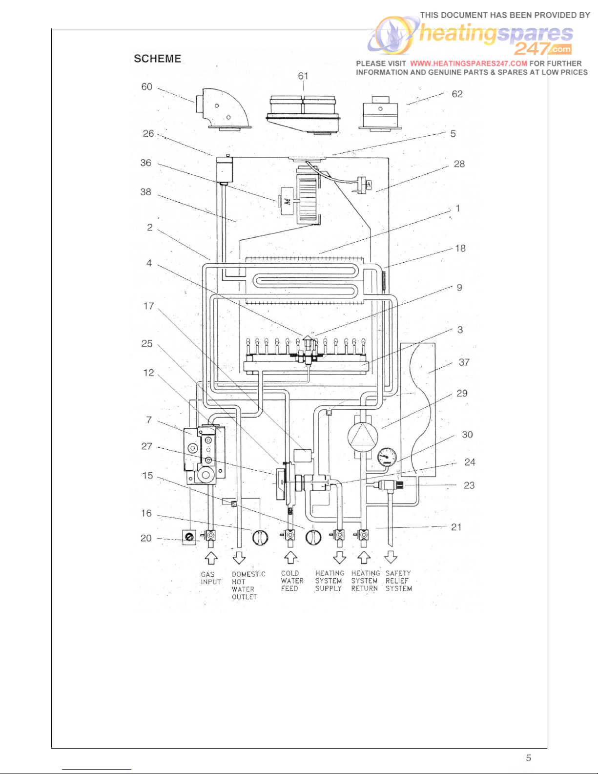
KEY
1 - Heat exchanger
3 - Burner
4 - Pilot burner
7 - Ignition board
9 - Ignition electrode
11 - Frame
12 - Modulating gas valve
15 - Heating control
16 - Hot water control
4
17- D.H.W. sensor
Water pressure switch (heating circuit)
18-
22 -
Overheat cut off thermostat
Safety relief systems
23 -
Three way valve
24 -
Auto air vent valve
26 -
Air pressure switch
28 -
Circulation pump
29 -
Water pressure gauge
30 -
33 - Main switch
34 - C.H. Sensor
36 - Fan
37 - Expansion tank
38 - Sealed chamber
45 - Combustion chamber
50 - Flue gas exhaust hood
105 -Timer
106 - Air restriction ring
Page 4
OPERATING
Fig. 2
KEY
1 - Heat exchanger
2 - Heat exchanger for D.H.W. water
3 - Burner
4 - Pilot burner
5 - Air restriction ring
7 - Electronic ignition
9 - Ignition electrode
12 - Modulating gas valve
15 - Heating control
16 - Hot water control
17 - Low water pressure switch
18 - Overheat cut-off thermostat
20 - Gas service cock
21 - Compression ball valves
23 - Safety relief system
24 - Three way valve
25 - Flow regulator
26 - Auto air vent valve
27 - D.H.W. pressure switch giving priority
28 - Air pressure switch
29
- Circulating
30 - Water pressure gauge
36
- Fan
37
- Expansion tank
38
- Sealed chamber
60
- Elbow header
61
- Twin header
62
- Straight header
pump
Page 5
SECTION 1
1.1
I NTRODUCTION
The Ravenheat boiler is for the use of central and domestic hot water combined in
one unit.
It is fitted with an automatic domestic hot
water priority valve.
A (winter/summer) selector switch is fitted to the left hand side of
control panel. With the only (summer)
position being for domestic hot water.
position being for central heating
with domestic hot water priority. The boiler
is equipped with a front cover which can be
removed for servicing. The data badge with
technical data is placed on the lower left
hand side of the frame.
2.2.6
2.2.7
switched off, the pressure switch returning
to its rest mode.
Central heating mode
If the switch is positioned on with
a demand for heat to supply radiators, etc.
With heating circuit fully charged so as to
operate the low water sensor device the
boiler will start in the same way as domestic hot water mode but with slightly differing
time delay in that it will start on minimum
and remain at this level for about 1 minute,
after which the flame will lift to its maximum
setting as governed by a potentiometer
range rates the heating circuit between
maximum and minimum power.
1.2
Fig. 1 Illustrates the general layout of com-
ponents.
Fig. 2 Illustrates the operating principles
described in section 2.
SECTION 2
2.1
DESCRIPTION OF CONTROL SYSTEM
AND SEQUENCE OF OPERATION
2.2
Domestic hot water mode
When the appliance is in rest mode with the
mains neon switch on. Switch the sum-
mer/winter switch in the position, mak-
ing sure the heating circuit is charged with
water (above 1 bar). When the domestic hot
water tap is turned on, the boiler will func-
tion in the following sequence:
2.2.1
The pump starts.
The control board sensors.
The fan operates via the pressure switch and
sends a signal back to the ignition board that
the fan is running at maximum speed.
2.2.2
The spark ignition system is powered which
in turn commences the spark igniter to
operate and light the burner.
At this point the ignition board opens the first
step of the gas valve to light the pilot/burner.
2.2.3
When the electrode/sensor senses the sig-
nal of the pilot/burner, it opens the second
stage of the gas valve via the ignition board
on minimum power. Upon the second valve
opening the spark igniter stops.
2.2.4 From the minimum gas rate setting the boiler increases to the maximum permissible
pressure over a period of 3 to 4 seconds
and will remain at its maximum required
power until its maximum regulated temperature.
2.2.5
When the domestic hot water tap is closed
the diverter valve goes back into rest mode,
the main burner is shut down along with the
pilot/burner. The pump and fan are also
2.2.8
2.2.9
2.3
2.3.1
2.3.2
2.3.3
2.3.4
2.3.5
2.3.6
2.3.7
On the control panel are mounted two
potentiometers (thermostats) these control
the temperature. One is for domestic hot
water and the other for heating.
The boiler is fitted with an anti-cycling
device on the control board. This delays the
boiler from re-firing over a 2.5 minute period
when in heating mode. The domestic hot
water will always take priority and is unaffected by the anti-cycling device.
GENERAL FUNCTION
Central Heating Mode
A potentiometer is installed on the electric
circuit board permits regulation of the boiler
to partial heating requirements, between
the factory setting.
Air is drawn by the fan for combustion.
The fan also forces exhaust gas through the
flue to the outside, this creates a lesser
pressure in the sealed combustion chamber, thus sucking in combustion air, through
the inlet duct.
The boiler water temperature is automatically controlled by a built in thermostat.
Interior space temperature is set by the
room thermostat to be installed in the heating system. The boiler already carries con-
nection terminals for this thermostat, as
well as for a timeclock. The burner will continue to operate until it is stopped by the
timer or one of the thermostats.
When the internal C.H. temperature sensor
intervenes the main burner shuts down. The
fan stops but the pump continues to oper-
ate.
When the room thermostats intervene the
main burner shuts down. The fan stops and
the pump turns off.
6
Page 6
2.4
2.4.1
2.4.2
2.4.3
2.4.4
2.4.5
Domestic hot water mode
The heat exchanger in the D.H.W. circuit is
built into the main heat exchanger, and
domestic water is heated by converting the
water in the central heating circuit. The
transference of heat is very high because
the two fluids-move in a counter direction
flow to each other.
Switch 33 in the (winter) position.
When a hot water tap is turned on a
diaphragm diverter valve excludes the central heating circuit, the boiler automatically
modulates to maintain the domestic hot
water at a constant temperature.
Water temperature can be regulated using
the D.H.W. thermostat located on the front
control panel.
When domestic hot water is being drawn
the main burner and pump perform as they
do during central heating except that the
burner is commanded by the D.H.W. ther-
mostat.
When D.H.W. is no longer called for the boil-
er automatically returns to the central heat-
ing mode.
Switch 33 in the (summer) position. The
boiler functions like an automatic gas hot
3.1
3.1.2
3.1.3
3.2.1
water heater. When D.H.W. is no longer
required the main burner fan and pump
immediately turn off.
This also takes place when switch 33 is on
(winter) if there is no demand for
heat to the central heating system or until
the room thermostat/time clock demands
for heat to the central heating circuit.
SAFETY DEVICE
In both central heating and domestic hot
water mode safe operating is ensured by:
- A differential pressure switch which shuts
off the main burner if the fan stops or the
flue or combustion air intake duct is
obstructed.
An overheat cut off thermostat set slightly
higher than the high limit thermostat acts to
turn off the burner to resetable “lockout”
(Fig. 50) item 3.
A safety valve fitted on the central heating
circuit set at 43 psi (3 bar).
A heating circuit (low water) pressure
switch is set at 0.4 bar.
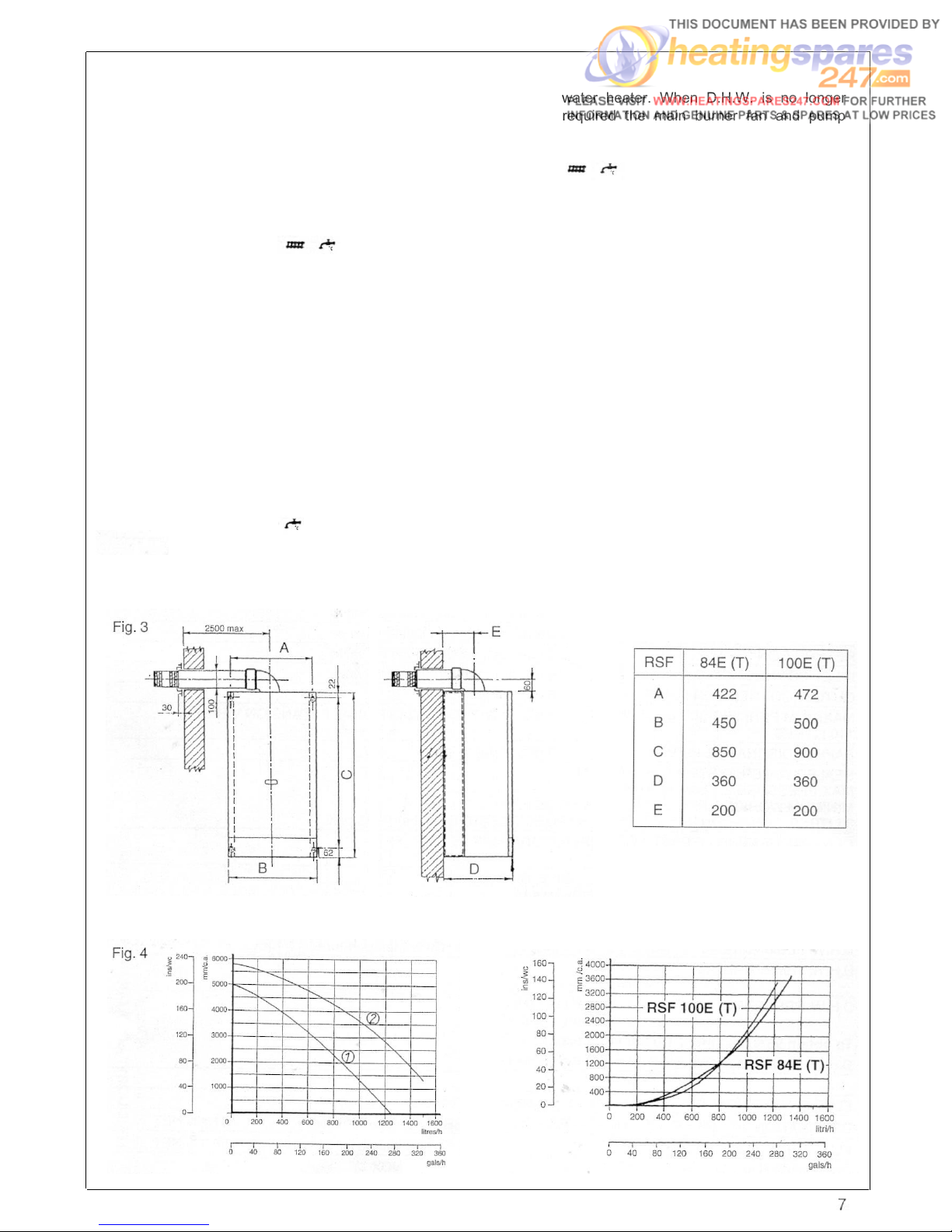
OVERALL DIMENSION
AVAILABLE PUMP HEAD
DIMENSIONS (mm)
PRESSUREDROP
ACROSS APPLIANCE
Fig. 5
Page 7
SECTION
3 TECHNICAL DATA
TABLE 1
HEAT INPUT NET
NOMINAL
HEAT OUTPUT
NOMINAL
GAS RATE
AFTER 10 minutes
INLET PRESSURE
BURNER PRESSURE
GAS CONTROL VALVE
MAIN BURNER
RSF 84E(T) NATURAL GAS (G 20) I2H
max
mid
min 14.6 kW
max
mid
min
max
mid
min
20 mbar
max
mid
min
SIT
POLIDORO MOD/NP
26.9 kW (91,800 Btu/h)
20.0 kW
24.58 kW (83,880 Btu/h)
17.6 kW
11.5 kW
3
/h
2.6 m
1.9 m3/h (67.1 ft3/h)
1.3 m3/h (45.9 ft3/h)
(8.0 in w.g.)
8.1 mbar (3.2 in w.g.)
4.0 mbar
1.5 mbar (0.6 in w.g.)
837 TANDEM
(68,250 Btu/h)
(49,800 Btu/h)
(60,060 Btu/h)
(39,250 Btu/h)
(91 .8 ft3/h)
(1.6 in wg.)
MAIN BURNER INJECTORS N. 13X1.35
PILOT BURNER
PILOT INJECTOR 0.27
ELECTRICAL SUPPLY
POWER CONSUMPTION
EXTERNAL FUSE RATING
INTERNAL FUSE RATING
DRY WEIGHT
WATER CONTENT D.H.W.
WATER CONTENT C.H.
GAS SUPPLY CONNECTION
FLOW CONNECTION C.H.
RETURN CONNECTION C.H.
INLET CONNECTION D.H.W.
OUTLET CONNECTION D.H.W.
POLIDORO PA525F
(MARKING) 2 HOLES
230V-50HZ
160W
3A
315mA - 2A - 4A (20mm to BS4265)
48 kg (106 Lbs)
0.5 Lts. (0.9 pints)
3.0 Lts. (5.3 pints)
15 mm compression isolating valve
22 mm compression isolating valve
22 mm compression isolating valve
15 mm compression isolating valve
15 mm compression
MAXIMUM PERMISSIBLE COLD WATER CAPACITY WITHOUT ADDITIONAL EXPANSION VESSEL
110 LITRES
SAFETY DISCHARGE PIPE
15 mm copper pipe
SEALED WATER SYSTEM C.H. SYSTEM
MAX PRESSURE 2.5 bar (35.6 p.s.i.)
MINIMUM WORKING PRESSURE 0.5 bar (7.35 p.s.i.)
8 LITRES EXPANSION VESSEL PRE-CHARGE-PRESSURE 0.5 bar (7.35 p.s.i.)
o
CENTRAL HEATING OPERATING TEMPERATURE MAX 85
MIN 45
o
DESIGN FLOW RATE 1057 I/h (236 gals) 20
C RISE
C
o
C
MINIMUM FLOW RATE C.H. 494 Lts/h (109 gals/h)
o
D.H.W. FLOW RATE 30
D.H.W. FLOW RATE 35
D.H.W. FLOW RATE 40oC rise
D.H.W. TEMPERATURE
D.H.W. PRESSURE
C rise 11.7 I/min (2.6 gals/min)
o
C rise 10.1 I/min (2.24 galslmin)
8.8 l/min (1.96 galsimin) 10 oC inlet temperature
max 65 oC
min 35
o
C
max 10 bar (147 p.s.i.)
min 0.8 bar (11.8 psi.)
To obtain 95% heat input 1.0 bar (14.5 p.s.i.)
D.H.W. MINIMUM FLOW RATE 3 I/m (0.66 gals/min)
FLUE OUTLET NOM. DIA. 100 m/m specially supplied with boilers
DESTINATION: AT - DK - FI - IE - IT - PT - ES - SE - CH - GB
FLUE TYPE - C12 - C32 - C
CATEGORY I
8
2H
52
Nominal Efficiency
1
Efficiency at 30% Load
NOX 2
91.4% NET
88.1% NET
Page 8

TECHNICAL DATA
TABLE 2
HEAT INPUT NET
NOMINAL
HEAT OUTPUT
NOMINAL
GAS RATE
AFTER 10 minutes
INLET
PRESSURE
BURNER P
RESSURE
GAS CONTROL VALVE
MAIN BURNER
RSF lOOE(T) NATURAL GAS (G 20) I 2H
max
mid
min
max
mid
min
max
mid
min
20 mbar
max
min
SIT
POLIDORO MOD/NP
32.79 kW
22.79 kW
13.96 kW
29.66 kW
20.3 kW
11.2 kW
3
/h
3.2 m
2.3 m3/h
3
1.4 m
/h
(8.0 in wg.)
12.5 mbar
5.0 mbar
1.4 mbar
637 TANDEM
(111,900 Btu/h)
(77,700 Btu/h)
(101,221 Btu/h)
(69,280 Btu/h)
(38,220 Btu/h)
(4.9 in w.g.)
(1.96 in w.g.)
(0.56 in w.g.)
MAIN BURNER INJECTORS N. 15X1.25
PILOT BURNER
PILOT INJECTOR 0.27
ELEC
TRICAL SUPPLY
R CONSUMPTION
POWE
RNAL FUSE RATING
EXTE
INTERNAL FUSE RATING
DRY WEIGHT
WATER CONTENT D.H.W.
WATER CONTENT C.H.
GAS SUPPLY CONNECTION
FLOW CONNECTION C.H.
RETURN CONNECTION C.H.
INLET CONNECTION D.H.W.
OUTLET CONNECTION D.H.W.
POLIDORO PA525F
(MARKING) 2 HOLES
230 V - 50HZ
160W
3A
315
mA - 2 A - 4 A (20 mm to BS4265)
(116.6 Lbs)
53 kg
Lts. (1.2 pints)
0.7
3.5
Lts. (5.2 pints)
15 mm compression
22 mm compressio
22 mm compressio
m compression isolating valve
15 m
15m
m compression
isolating
valve
n isolating valve
n isolating valve
MAXIMUM PERMISSIBLE COLD WATER CAPACITY WITHOUT ADDITIONAL EXPANSION VESSEL
11O LITRES
SAFETY DISCHARGE PIPE
15 mm copper pipe
SEALED WATER SYSTEM C.H. SYSTEM
MAX PRESSURE 2.5 bar (35.6 p.s.i.)
MINIMUM WORKING PRESSURE 0.5 bar (7.35p.s.i)
8 LITRES EXPANSION VESSEL PRE-CHARGE-PRESSURE 0.5 bar (7.35 p.s.i.)
O
CENTRAL HEATING OPERATING TEMPRATURE MAX 85
C
MIN 45oC
DESIGN FLOW RATE 1275 I/h (283 gals) 20 OC RISE
MINIMUM FLOW RATE (106 gals/h)
D.H.W. FLOW RATE 30 oC rise 14.2 I/min (3.16 gals/min)
D.H.W. FLOW RATE 35
D.H.W. FLOW RATE 40
TEMPERATURE
D.H.W
o
C rise 12.2 I/min (2.7 galsimin)
o
C rise I0.6 I/min (2.4 gals/min) 10o C inlet temperature
max 65
o
C
min 35 °C
D.H.W. PRESSURE
max 10 bar (147 p.s.i.)
min 0.8 bar (11.8 p.s.i.)
To obtain 95% heat input 1.7 bar (24.7 p.s.i.)
D.H.W. MINIMUM FLOW RATE 3 I/m (0.66 gals/min)
FLUE OUTLET NOM. DIA. 100 m/m specially supplied with boilers
DESTINATION: AT - DK - FI - IE - IT - PT - ES - SE - CH - GB
FLUE TYPE - C12 - C32 C52
CATEGORY I
2H
Nominal Efficiency
Efficiency at 30% Load
NOX 2
90.47% NET
89.4% NET
9
Page 9
TECHNICAL DATA
TABLE 3
HEAT INPUT NET
NOMINAL
HEAT OUTPUT
NOMINAL
GAS RATE
AFTER 10 minutes
INLET PRESSURE
BURNER PRESSURE
GAS CONTROL VALVE
MAIN BURNER
RSF 84E(T) PROPANE GAS (G 31) I 3P
max
mid
min
max
mid
min
max
mid
min
37 mbar
max
mid
min
SIT
POLIDORO MOD/NP
26.9 kW
20.0 kW
13.5 kW
24.58 kW
17.6 kW
10.7 kW
1.05 m3/h
0.82 m3/h
0.52 m3/h
(14.85 in w.g.)
20.5 mbar
14.8 mbar
4.4 mbar
837 TANDEM
(91,800 Btu/h)
(68,200 Btu/h)
(46,000 Btu/h)
(83,880 Btu/h)
(60,060 Btu/h)
(36,506 Btu/h)
(37,07 ft3/h)
(28,95 ft
(18,36 ft
(8.23 in wg.)
(5.94 in w.g.)
(1.77 in w.g.)
MAIN BURNER INJECTORS N. 13X0.85
PILOT BURNER
PILOT INJECTOR 0.22
ELECTRICAL SUPPLY
POWER CONSUMPTION
EXTERNAL FUSE RATING
INTERNAL FUSE RATING
DRY WEIGHT
WATER CONTENT D.H.W.
WATER CONTENT C.H.
GAS SUPPLY CONNECTION
FLOW CONNECTION C.H.
RETURN CONNECTION C.H.
INLET CONNECTION D.H.W.
OUTLET CONNECTION D.H.W.
POLIDORO PA525F
(MARKING) 1 HOLE
230V-50HZ
160W
3A
315mA-2A-4A (20mmtoBS4265)
48 kg (106 Lbs)
0.5 Lts. (0.9 pints)
3.0 Lts. (5.3 pints)
15 mm compression isolating valve
22 mm compression isolating valve
22 mm compression isolating valve
15 mm compression isolating valve
15 mm compression
MAXIMUM PERMISSIBLE COLD WATER CAPACITY WITHOUT ADDITIONAL EXPANSION VESSEL
110 LITRES
SAFETY DISCHARGE PIPE
15 mm copper pipe
SEALED WATER SYSTEM C.H. SYSTEM
MAX PRESSURE 2.5 bar (35.6 p.S.i.)
MINIMUM WORKING PRESSURE 0.5 bar (7.35 p.s.i.)
8 LITRES EXPANSION VESSEL PRE-CHARGE-PRESSURE 0.5 bar (7.35 p.s.i.)
CENTRAL HEATING OPERATING TEMPERATURE MAX 85
MIN 45
o
DESIGN FLOW RATE 1057 l/h (236 gals) 20
C RISE
o
C
o
C
MINIMUM FLOW RATE C.H. 494 Lts/h (109 gals/h)
o
D.H.W. FLOW RATE 30
D.H.W. FLOW RATE 35
D.H.W. FLOW RATE 40oC rise
D.H.W. TEMPERATURE
C rise 11.7 l/min (2.6 galslmin)
o
C rise 10.1 l/min (2.24 gals/min)
8.8 l/min (1.96 gals/min) 10 oC inlet temperature
max 65 o C
min 35°C
D.H.W. PRESSURE
max 10 bar (147 p.s.i.)
min 0.8 bar (11.8 p.s.i.)
To obtain 95% heat input 1.0 bar (14.5 p.S.i.)
D.H.W. MINIMUM FLOW RATE 3 l/m (0.66 galS/min)
3
/h)
3
/h)
FLUE OUTLET NOM. DIA. 100 m/m specially supplied with boilers
DESTINATION: BE - FR - IE - PT - ES - GB - CH
FLUE TYPE - C12 - C32 - C
CATEGORY I
10
3P
52
Nominal Efficiency
Efficiency at 30% Load
NOX 2
91.4% NET
88.1% NET
Page 10
TECHNICAL DATA
TABLE 4
HEAT INPUT NET
NOMINAL
HEAT OUTPUT
NOMINAL
GAS RATE
AFTER 10 minutes
INLET PRESSURE
BURNERPRESSURE
GAS CONTROL VALVE
MAIN BURNER
RSF lOOE(T) PROPANE GAS (G 31) I 3P
max
mid
min
max
mid
min
max
mid
min
37 mbar
max
mid
min
SIT
POLIDORO MOD/NP
32.82 kW
21.39 kW
14.00 kW
29.66 kW
19.1 kW
11.2 kW
1.3 m3/h
0.8 m3/h
0.6 m3/h
(14.85 in w.g.)
23.5 mbar
9.3 mbar
3.7 mbar
837 TANDEM
(112,000 Btu/h)
(73,000 Btu/h)
(47,800 Btu/h)
(101,221 Btu/h)
(65,170 Btu/h)
(38,220 Btu/h)
(45.9 ft3/h)
(28.2 ft
(21.2 ft
(9.43 in w.g.)
(3.73 in w.g.)
(1.48 in w.g.)
MAIN BURNER INJECTORS N. 15X0.85
PILOT BURNER
POLIDORO PA525F
PILOT INJECTOR 0.22 (MARKING) 1 HOLE
ELECTRICAL SUPPLY
230V-50HZ
POWER CONSUMPTION 160W
EXTERNAL FUSE RATING
INTERNAL FUSE RATING
DRY WEIGHT
WATER CONTENT D.H.W.
WATER CONTENT C.H.
GAS SUPPLY CONNECTION
FLOW CONNECTION C.H.
RETURN CONNECTION C.H.
INLET CONNECTION D.H.W.
OUTLET CONNECTION D.H.W.
3A
315mA-2A-4A (20mmtoBS4265)
53 kg (116.6 Lbs)
0.7 Lts. (1.2 pints)’
3.5 Lts. (5.2 pints)
15 mm compression isolating valve
22 mm compression isolating valve
22 mm compression isolating valve
15 mm compression isolating valve
15 mm compression
MAXIMUM PERMISSIBLE COLD WATER CAPACITY WITHOUT ADDITIONAL EXPANSION VESSEL
110 LITRES
SAFETY DISCHARGE PIPE
15 mm copper pipe
SEALED WATER SYSTEM C.H. SYSTEM
MAX PRESSURE 2.5 bar (35.6 p.s.i.)
MINIMUM WORKING PRESSURE 0.5 bar (7.35 p.s.i.)
8 LITRES EXPANSION VESSEL PRE-CHARGE-PRESSURE 0.5 bar (7.35 p.s.i.)
CENTRAL HEATING OPERATING TEMPERATURE MAX 85
MIN 45
DESIGN FLOW RATE 1275 I/h (283 gals) 20
o
C RISE
o
C
o
C
MINIMUM FLOW RATE C.H. 481 Lts/h (106 gals/h)
o
D.H.W. FLOW RATE 30
D.H.W. FLOW RATE 35
D.H.W. FLOW RATE 40
D.H.W.TEMPERATURE
C rise 14.2 l/min (3.16 gals/min)
o
C rise 12.2 I/min (2.7 gals/min)
o
C rise 10.6 l/min (2.4 gals/min) 10 oC inlet temperature
max 65 oC
min 35°C
D.H.W. PRESSURE
max 10 bar (147 p.s.i.)
min 0.8 bar (11.8 p.s.i.)
To obtain 95% heat input 1.7 bar (24.7 p.s.i.)
D.H.W. MINIMUM FLOW RATE 3 I/m (0.66 gals/min)
3
/h)
3
/h)
FLUE OUTLET NOM. DIA. 100 m/m specially supplied with boilers
DESTINATION: BE - FR - IE - PT - ES - GB - CH
FLUE TYPE C12 - C32 - C
CATEGORY I
3P
52
Nominal Efficiency
Efficiency at 30% Load
NOX 2
90.47% NET
89.4% NET
11
Page 11
SECTION 4
4.0
4.1
GENERAL REQUlREMENTS
SAFETY
Gas Safety (Installation and Use)
Regulations, 1994 and amended 2000.
It is law that all gas appliances are installed
and serviced by a CORGI registered
installer in accordance with the above regulations and these installation instructions.
All CORGI registered installers carry a
CORGI I.D. card and have a registration
number. Both should be recorded in your
boiler log book. You can check your installer
by calling CORGI direct on: 01256 732300.
Failure to install appliances correctly could
lead to prosecution. It is in your own interest, and that of safety, to ensure the law is
complied with. Check the boiler and flue is
the correct type for installation.
The installation of the boiler MUST be in
accordance with the latest I.E.E. (BS 7671)
Wiring Regulations, local building regulations, bye-laws of the local water authority,
the building regulations and the Building
Standards (Scotland) and any relevant
requirements of the local authority.
GENERAL INFORMATION
Both the user and the manufacturer rely heavily on the installer, whose job it is to install the
combination boiler and connect it to a correctly designed heating system. Acquaint yourself
with the British Standards concerning installation requirements. If you need advice on any
points your Ravenheat Technical Services
Office would be pleased to help. It is recom-
mended that tools suitable for brass fittings
are used, and have a capability to accommodate hexagon sizes up to 50 mms.
CODES OF PRACTICE/Ref: Documents
Detailed recommendations are contained in
the following British Standard Codes of
Practice:
4.2
4.2.1
IMPORTANT. These appliances are CE cer-
tificated for safety and performance. It is,
therefore, important that no external control
devices e.g. flue dampers, economisers
etc., are connected to this appliance unless
covered by these directly Installation and
Servicing Instructions or as otherwise recommended by Ravenheat in writing. If in
doubt please enquire.
Any direct connection of a control device
not approved by Ravenheat could invalidate
the certification and the normal appliance
warranty. It could also infringe the Gas
Safety regulations and the above regulations.
NOTE: The Ravenheat combination boiler
has been tested an examined by Bg Technology Certification Services and is certified to comply with PrEN 483 and BS EN
625.
Manufacturers instructions must NOT be
taken in any way as overriding statutory
obligations.
If in doubt on any point please consult
Ravenheat Manufacturing Ltd.
LOCATION OF BOILER
Siting of Ravenheat RSF Combi Boiler must
be as follows. The position of installation
should be within the building, unless otherwise protected by suitable enclosure.
Adequate space for installation, servicing
and air circulation around boiler must be
allowed for.
The Ravenheat RSF Combi Boiler must be
fitted on a flat and vertical wall capable of
adequately supporting the weight of the
boiler and any ancillary equipment.
The appliance may be installed on a com-
bustible wall subject to the requirements of
the Local Authority and Building Regulations.
BS. 6891
BS. 6798
Low pressure installation pipes
Installation of gas fired hot
water boilers of rated input not
exceeding 60 kW.
BS. 5449
Forced circulation hot water
systems.
BS. 5546
Installation of gas hot water
supplies domestic purposes
(2nd Family Gases).
BS. 544O:1
Flues (for gas appliances of rated
input not exceeding 60 kW).
BS. 5440:2 Ventilation (for gas appliances of
rated input not exceeding 60 kW).
Health & Safety Document No. 635
The Electricity at Work Regulations, 1989.
12
4.3
4.3.1
CLEARANCES AROUNDTHE
APPLIANCE
The following minimum free spaces, required for installation inspection and servicing, must be left around the boiler.
RSF 84E (T)
Above 125 mm
RSF 1OOE (T)
Above 150 mm
Below 100 mm Below 100 mm
Front 450 mm Front 450 mm
Side 75 mm
Side 5 mm
25 mm in front when installed in a cupboard
Page 12

4.4
4.4.1
4.5
4.51
IMPORTANT NOTICE ply is available both to the boiler and the
other appliances when they are in use at
If the combination boiler is to be fitted in a the same time.
timber framed building it should be fitted in
accordance with the British Gas Publication
4.6
FLUE SYSTEM
Guide for Gas installations in Timber Frame
Housing Reference IGE/UP/7/1998. If in
4.6.1
The terminal should be located where disdoubt advice must be sought from the local persal of combustion products is not impedgas supplier. The combination boiler may be
installed in any room or internal space,
ed, and with due regard for the damage or
discolouration that might occur to building
although particular attention is drawn to the products in the vicinity (see fig. 6).
requirements of the current I.E.E. Wiring The terminal must not be located in a place
Regulations and in Scotland the electrical where it is likely to cause a nuisance.
provisions of the Building Regulations
The terminal must not be closer than 25
applicable in Scotland, with respect to the mm. (1 in) to any combustible material. For
installation of the combination boiler in a protection of combustibles, refer to BS
room or internal space containing a bath or
shower.
5440.1.
Where a flue terminal is installed less than
Where a room sealed appliance is installed 1000 mm. from a plastic, or painted gutter;
in a room containing a bath or shower, any
or 500 mm from painted eaves, an aluminielectrical switch or appliance control utilis- um shield 1000 mm. long, should be fitted
ing mains electricity should be so situated
that it cannot be touched by a person using
a bath or shower.
to the underside of the gutter or painted
surface.
The flue must be installed in accordance
A compartment used to enclose the combi- with the recommendations of BS 5440:
nation boiler MUST be designed and con-
Part 1.
structed specifically for this purpose. An
existing cupboard, or compartment, may be
used provided it is modified accordingly.
Samples of the RSF 84E/84ET - RSF
IMPORTANT NOTICE: if the flue terminates less than
2 M. above a balcony, above the ground, or above a
flat roof to which people have access, then a suitable
1OOE/1OOET combination boilers have terminal guard must be fitted.
been examined by B.G.Technology Notified
Body, and are certified to comply with the
Fit only recommended flue terminal guard by secur-
ing concentrically around terminal with screws.
essential requirements of the Gas Appliance Directive 90/396/EEC, the Low Voltage Directive 72/23/EEC and shows compliance with the Electro Magnetic Compatibility Directive 89/336/EEC and are therefore permitted to carry the CE Mark.
Available on request from:
RAVENHEAT Manufacturing Ltd
Chartists Way
Morley, Leeds, West Yorkshire
ENGLAND LS27 9ET - U.K.
Tel. 0113 252 7007
The appliance has been tested and
approved by the WRc as meeting the
requirements of G3 and L of the Building
IMPORTANT: The following notes are
intended for general guidance.
regulations and water Bylaws Scheme Approved Products. The boiler MUST be installed so that the
terminal is exposed to external air.
GAS SUPPLY
It is important that the position of the termi-
A gas meter is connected to the service pipe
by the Local Gas Supplier or a contractor.
nal allows the free passage of air across it
at all times.
An existing meter should be checked preferably by the gas Region to ensure that the Minimum acceptable spacing from the termeter is adequate to deal with the rate of minal to obstructions and ventilation open-
gas supply required for all appliances it
ing are specified in Fig. 6.
serves. Installation pipes should be fitted in
accordance with BS 6891. Pipework from Note positions: Due to the terminal
the meter to the boiler must be of adequate
size (22 mm) min. To within at least 3 metre
Of the boiler (15 mm) min. can then be used
design, installation is possible with clearances less than those specified in BS 5440,
Part 1.
for remaining pipe work to the appliance. A
smaller size than the boiler inlet gas connection should not be used. The complete
installation must be tested for soundness as
described in the above Code.
N.B. if the gas supply for the boiler serves
other appliances ensure an adequate sup-
13
Page 13
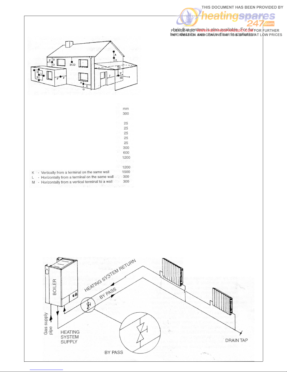
Fig. 6
4.6.3
A twin flue system is also available. For fur-
ther details see twin flue installation
instruction (sect. 10).
Terminal position for
fan assisted boiler
(minimum distance)
Directly below an open window or other
A
opening (e.g. air brick)
B
- Below gutters, soil pipes or drain pipes
C - Below eaves
D
- Below balconies or car port roof
E
- From vertical drain pipes and soil pipes
F
- From internal or external corners
G
- Above ground or below balcony level
H
- From a surface facing a terminal
I
- From a terminal facing a terminal
J
From an opening in the car port (e.g. door
window) into dwelling.
NOTE:
The flue must be terminated in a place not
likely to cause a nuisance.
FLUE ALTERNATIVES
4.6.2
A concentric vertical flue kit is available for
flueing applications up to a maximum
height of 4 metres vertically. For further
details see vertical flue installation instructions (sect. 5.7.12).
4.7
4.7.1
AIR SUPPLY
The following notes are intended for general guidance.
The room sealed fan flued boiler does not
require a permanent air vent for combustion air supply.
Where installed in a cupboard or compartment ventilation is not required.
4.8
4.8.1
WATER CIRCULATION (central heating)
Detailed recommendation are given in BS
6798:1987/5449:1990 (for smallbore and
microbore central heating systems). The following notes are given for general guidance.
4.8.2 Pipework
Copper tubing to BS 2871 1 .1 .1971 is recommended for water pipes. Jointing should
be either with capillary soldered or with
compression fittings.
Where possible pipes should have a gradient to ensure air is carried naturally to air
release points and water flows naturally to
drain taps. It should be ensured as far as
possible that the appliance heat exchanger
is not a natural collecting point for air
except where providing useful heat, pipes
should be insulated to prevent heat loss
and to avoid freezing. Particular attention
should be paid to pipes passing through
ventilated spaces in roofs and under floors.
4.8.3
The water through the appliance heat
exchanger circuit must exceed the min.
2.38 gals/min. (650 It/h) when the burner is
firing. It is important to ensure that this rate
is achieved when sections of the system
are shut off either manually or by automatic
controls. Therefore a by-pass must be fit-
ted to the system (15 mm min.) (Fig. 6A).
14
Fig.
6A
Page 14
4.8.4
4.8.5
4.8.6
If the volume of circulating water is too low,
the boiler water temperature will rise too
rapidly. This could cause noise in the system or even cause the overheat cut off to
lockout.
Draining tap
These must be located in accessible positions to permit the draining of the whole
system. The taps must be at least 15 mm
nominal size and manufactured in accordance with BS 2870 1980.
Air release points
These must be fitted at all high points
where air will naturally collect, and must be
sited to facilitate complete fitting of the system.
The appliance has an integral sealed
expansion vessel to accommodate the
increase of water volume when the system
is heated. It can accept up to 1.5 gal (7 Its)
of expansion water. If the appliance is con-
nected to a system with an unusually high
water content, calculate the total expansion
and add additional sealed expansion
capacity as appropriate (Fig. 7).
In general modern systems will present no
problem.
located, between the cistern and the auto-
matic air vent. The stop valve may remain
open during normal operation of the system,
if automatic water make-up is
required.
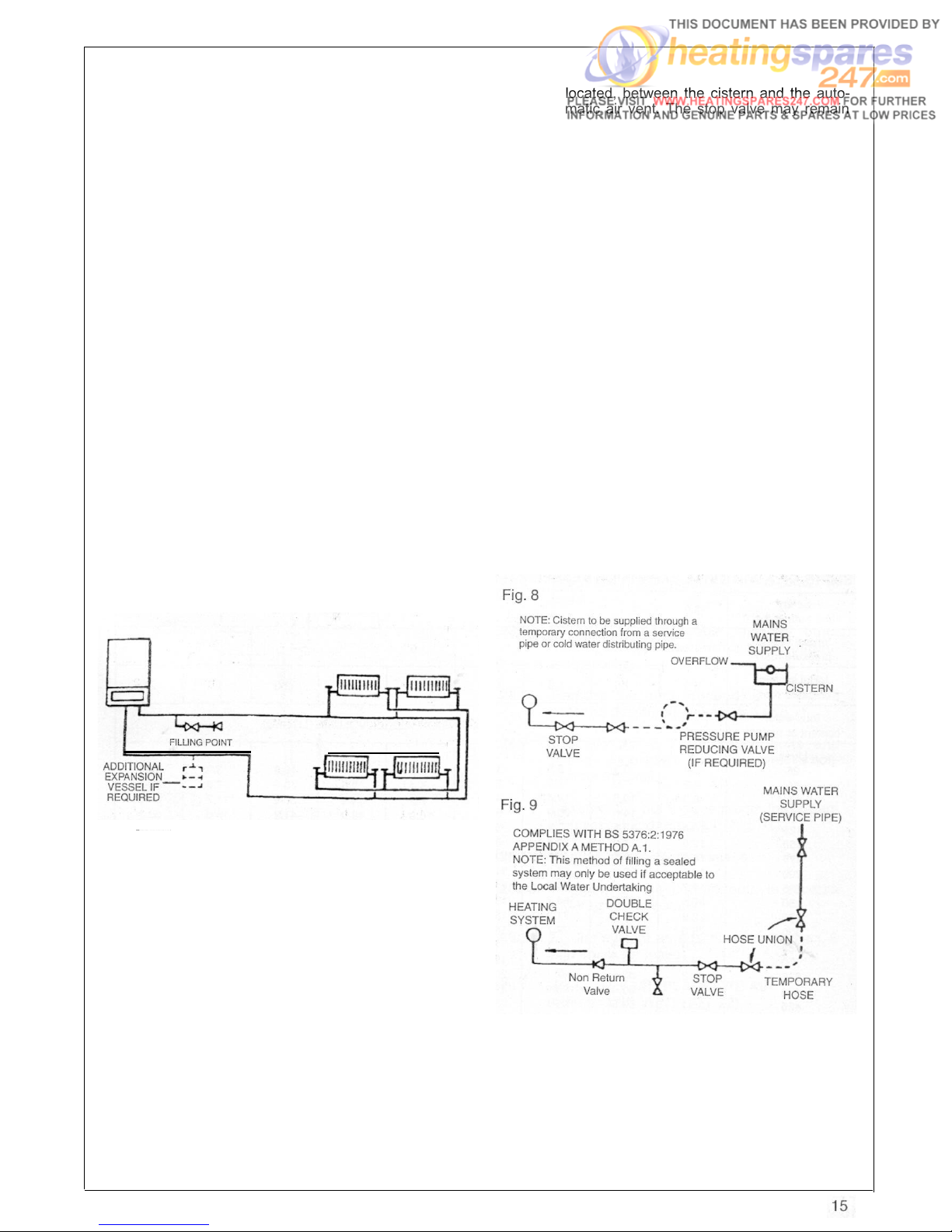
Booster pump method (Fig. 8).
The system may be filled through a self
contained unit comprising of a cistern pressure booster pump if required and if necessary an automatic pressure reducing valve
or flow restrictor. The cistern should be
supplied through a temporary connection
from a service pipe or cold water distributing pipe. The unit may remain permanently
connected to the heating system to provide
limited automatic water make up.
Mains topping up method (Fig. 9).
Here the temporary connection is supplied
from a service pipe, or distributing pipe,
which also supplies other draw-off points at
a lower level.
A combined double check valve shall be
installed upstream of the draw-off point,
through a temporary hose connection from
a tap supplied from the mains, where the
mains pressure is excessive a pressure
reducing valve shall be used to make filling
easier. The following fittings shall form a
permanent part of the system and shall be
fitted in the order stated.
Fig. 7
4.8.7
4.8.8
Mains water feed: central heating
There must be no direct connection to the
mains water supply, even through a nonreturn valve, without the approval of the
Local Water Authority.
Permissible methods of filling
Cistern method (Fig. 8).
The system may be filled by one of the following methods. Through a cistern used for
no other purpose, via a ballvalve permanently connected directly to a service pipe
and/or cold water distributing pipe. The sta-
tic head available from the cistern should
be adequate to provide the initial system
design pressure.
The cold feed pipe from the cistern should
include a non-return valve, and a stopvalve with an automatic air vent connected
between them, with the stop valve being
a) A stop valve complying with the require-
ments of BS 1010 Part 2 (the temporary
hose from the draw off tap shall be con-
nected to this fitting).
b) A test clock.
c) Double check valve of an accepted type.
d) A non return valve of an accepted type.
Page 15

We recommend use of a Ravenheat be at least l/2" in BSP nominal size and be
Filling Loop designed for this method of in accordance with BS 2879.
filling the system. Available from your
supplier.
4.8.9
lnstallation to an existing central heating
system
PROVISIONS FOR MAKE UP WATER The combination boiler is designed to oper-
(Fig. 7)
Provision can be made for replacing water
loss from the system either.
A) from a manually filled made up bottle
with a readily visible water level. The bottle
should be mounted at least 150 mm (6 in)
ate on a sealed system only. Therefore if
the existing system is of the open water
type it will have to be modified to comply
with BS 5376 Part 2.
Before installing a new combination boil-
er to an existing system flush out the old
above the highest point of the system and system with a recommended descaling
be connected through a non return valve to
the return side of the heating system.
agent.
Also check pipework and renew any corrod-
B) Where fitting a make up vessel would be ed pipework or fittings, Valve glands must
difficult re pressurisation of the system can
be done. See section on FILLING.
be repacked or replaced wherever necessary and any defective controls exchanged.
If the capacity of the central heating system
should exceed 110 litres, an additional 4.8.10
vessel may be installed if required on the
return to the combination boiler from the
heating system (Fig. 7). Guidance on ves-
sel sizing is given in (Table 5).
Reference should be made to British Gas
Hard water areas
If the area of installation is recognized as a
hard water, it is recommended that a suitable water treatment device is installed in
the mains.
The water hardness can be determined by
Publications << Material and Installation using the standard test paper or by referSpecifications for Domestic Central Heat-
ring to local water authority.
ing and Hot Water >>. Draining taps should
SIZING OF ADDITIONAL EXPANSION VESSELS:TABLE 5
Safety
valve setting (bar)
Vessel charge
pressure (bar)
Initial system
pressure (bar)
Total water
content Of System
Litres
25
50 4.2
75
100
125 10.4 17.5 32.4 68.9 13.6 23.7 51.5 19.5 41.3
150 12.5 21.0 38.8 82.6 16.3 28.5 61.8 23.4 49.6
175 14.6 24.5 45.3 96.4 19.1 33.2 72.1 27.3 57.9
200 16.7 28.0 51.8 110.2 21.8 38.0 82.4 31.2 66.2
225 18.7 31.5 58.3 124.0 24.5 42.7 92.7 35.1 74.5
250 20.8 35.0 64.7 137.7 27.2 47.5 103.0 39.0 82.7
275 22.9 38.5 71.2 151.5 30.0 52.2 113.3 42.9
300 25.0 42.0 77.7 165.3 32.7 57.0 123.6 46.8 99.3
325 27.0 45.5 84.1 179.1 35.7 61.7 133.9 50.7 107.6
350 29.1 49.0 90.6 192.8 38.1 66.5 144.2 54.6 115.8
375 31.2 52.5 97.1 206.6 40.9 71.2 154.5 58.5 124.1
400 33.3 56.0 103.6 220.4 43.6 76.0 164.8 62.4 132.4
425 35.4 59.5 110.1 239.2 46.3 80.7 175.1 66.3 140.7
450 37.5 63.0 116.5 247.9 49.0 85.5 185.4 70.2 148.9
475 39.6 66.5 123.0 261.7 51.8 90.2 195.7 74.1 157.2
500 41.6 70.0 125.9 275.6 54.5 95.0 206.0 78.0 165.5
3.0
0.5
0.5
2.1
6.3
8.3 14.0 25.9 55.1 10.9 19.0 41.2 15.6 33.1
1.0 1.5
3.5 6.5 13.7
7.0
10.5 19.4
12.9
2.0 1.0
EXPANSION VESSEL VOLUME (LITRES)
27.5
41.3
1.0
1.5
2.7 4.7
5.4
8.2
9.5 20.6
14.2 30.9 11.7 24.8
2.0
10.3
1.5
3.9
7.8 16.5
2.0
8.3
91.0
For system volumes
other than those given
above, multiply the
system volume by
the factor across
16
0.0833 0.140 0.259 0.551 0.109 0.190 0.412 0.156 0.331
Page 16
4.9
DOMESTIC WATER
5.2
DELIVERY
4.9.1
The domestic hot water must be in accordance with the relevant recommendations
of BS 5546. Copper tubing to BS 2871.1 is
recommended for water carrying pipework
and MUST be used for pipework carrying
potable water..
4.10 ELECTRICAL SUPPLY
Warning: this appliance must be earthed
4.10.1
External wiring to the appliance must be
carried out by a competent person and be in
accordance with the current I.E.E. Regulations and local regulations which apply.
The Ravenheat boiler is supplied for connection to a 230 V - 50 Hz single phase
supply. The supply must be fused at 3 A.
NOTE: The method of connection to the
electricity supply MUST facilitate complete
electrical isolation of the appliance, by the
use of a fused, double pole isolator, having
a contact separation of at least 3 mm in all
poles. The point of connection to the electricity supply must be readily accessible and
adjacent to the appliance except, where the
appliance is installed in a bathroom, this
MUST be sited outside the bathroom.
5.2.1
The appliance will arrive on site in three
cartons:
Boiler carton containing:
a) boiler fully assembled
b) installation instructions and
user instructions
c) white paper template
d) terminal cover plate (Fig. 12 item 127)
g) - 4 coach bolts and wall plugs
- screws and dowels
h) header gasket (Fig. 12 item 56)
Valve pack carton containing:
a) 2-22 mm compression ball valves
(heating)
b) 1-1 5 mm compression ball valve
(with drain screw for domestic cold
water inlet)
c) 1-1/2" BSP Union gas cock
d) Polythene bag containing
2 15 mm flanged copper tails complete
with 1/2" brass nuts and washers
- 2 22 mm flanged copper tails complete
with 3/4" brass nuts and washers
Fig. 10
SECTION 5 INSTALLATION
5.1
5.1.1
WARNING
It is MOST IMPORTANT that this appliance
is installed in a VERTICAL POSITION, with
the flue air duct passing through the wall in
a HORIZONTAL PLANE. A minor deviation
from the horizontal is acceptable, provided
that this results in a downward slope of the
flue/air duct away from the combination
boiler.
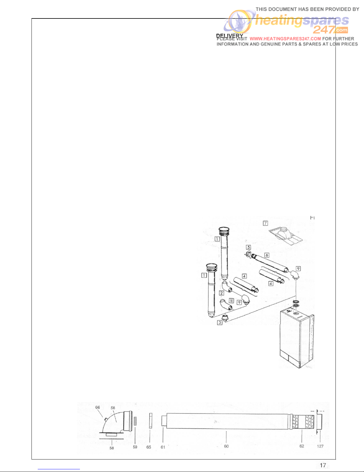
Flue box containing (Fig. 12):
Standard Flue Assembly
57
- Flue bend assembly
59
- Rubber seal 0 60
60 - Air intake duct
61
- Flue exhaust duct
62
- Terminal
65
- Pipe centering spring
66
- Flue sample point
For vertical flue
system see sect. 5.7.12
(Minimum vertical 1100 mm)
Fig. 12
Page 17
5.2.2
OPTIONAL EXTRAS:
a) Straight header (Fig. 10) item 3.
b) 1000 mm flue extension.
c) Concentric 90” in-line bend (Fig. 10)
item 2.
d)
Concentric vertical flue
(Fig. 10)
item 1.
e) Concentric 45” in-line bend (Fig. 10)
item 10.
Fig. 13
FLUE EXTENSION BOX CONTAINING (Fig. 14):
1000 mm flue extension duct as an extra cost only
when requested for side and vertical flue applications
59 - Rubber seal 0 60
63 Air intake duct extension
64 - Flue exhaust duct extension
65 - Pipe centering spring
STRAIGHT HEADER BOX CONTAINING (Fig. 13):
55 - Rubber seal 0 100
57 - Straight header supplied as an extra cost Only
when requested
59 Rubber seal 0 60
66 - Flue gas sample point
5.3
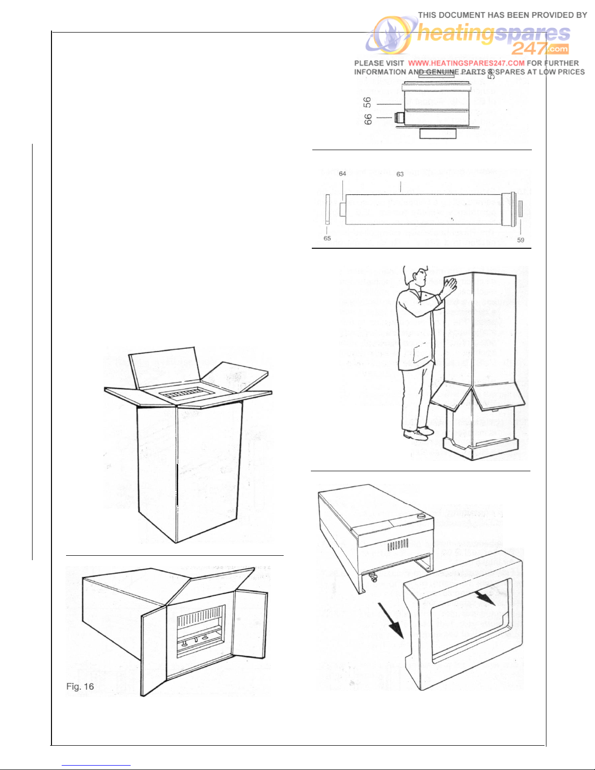
UNPACKING
Fig. 14
Fig. 17
3)
Turn the carton over,
with the boiler inside
and then pull the carton
Fig. 15
1) Open the top
of the carton
2) Rest the carton on
the floor (keeping the flaps open)
18
Fig. 18
4) Rest the boiler on the floor and remove
the polystyrene guards
Page 18

5.4
POSITIONING OF THE BOILER
Fig. 22
5.4.1
5.4.2
Fig. 19
- Remove the 2 screws that secure the
upper part of the front panel of the casing (Fig. 19).
- Carefully slide the front panel a few millimetres up towards the top of the appli-
ance until it is free from its slot, and
then lift off Fig. 20).
Unscrew the 2 screws that fasten the lower
grating on the casing and remove it from
the sides of the casing (Fig. 22).
Fig. 23
Fig. 21
Fig. 25
TABLE 6
19
Page 19

5.4.3
Push down the 2 plastic clips that fasten
the instrument panel (Fig. 23).
Fig. 26
5.4.4
5.4.5
5.4.6
5.5
5.5.1
Lower the instrument panel down by rotating it on its own hinges (Fig. 25).
Unscrew the two screws that fasten the two
side panels.
Remove the two sides of the casing by
slightly lifting them and carefully sliding
towards the top of the appliance, to release
them from their upper suspension hooks
(Fig. 26-27).
Make sure the casing and screws are put
to one side in a safe place.
INSTALLING THE APPLIANCE FOR
REAR FLUE OUTLET
Use adhesive tape to attach the template
to the wall, making sure that the centre line
is vertical.
- Mark the four boiler fastening holes on
the wall as well as the centre of the flue
duct.
-
Detach the template from the wall.
- Use a 10 mm. dia drill to make the 4 boiler securing holes. Insert the plastic
expansion plugs.
-
Cut or core drill a 105 mm. dia hole for
inserting the flue duct.
- Screw in the two upper coach bolts leaving them about 10 mm. out from the wall
to enable the boiler to be located on the
wall.
Fig. 27
Fig. 26
Fit the elbow header positioning it towards
the required direction (Fig. 30).
IMPORTANT: Make sure that the elbow’s
dia. 60 mm duct is inserted into the fan, the
rubber seal and orifice are been correctly
fitted.
Fig. 29
20
Page 20

5.5.3
If the standard duct furnished with the boiler is too long (the wall to go through is less
than 680 mm thick) it can be shortened as
follows:
- Remove the centering spring 65, the flue
terminal to disengage inner flue duct.
- Measure the thickness W of the wall.
- Cut the outer flue duct at right angles to
a length equal to W + 152 mm.
Must be de-burred.
Fig. 30
Orifice plate
concentric
flue system
RSF 84E= 81
RSF 1OOE= 79
- Cut the inner flue duct (60 mm) at right
angles to a length equal to W + 264 mm.
Insert from cut end. Reassemble the two
tubes. Insert centering spring 65.
Must be de-burred.
Reassemble together inner and outer flue
duct insert centering spring.
Fig. 32
INTAKE AND EXHAUST TERMINAL COMPONENTS
Fig. 31
KEY
59 Rubber seal 0 60 64 - Flue exhaust duct extension
60 - STD air intake duct
56 - Straight header
57 - Elbow header
58 - Header gasket
61 - STD flue exhaust duct
62 -Terminal
63 -Air intake duct extension
65 - Pipe centering spring
66 - Sample point
127 -Terminal cover plate
128 - Screw
21
Page 21

5.5.4
Insert the flue assembly into the wall, being
careful to make sure that the outer air duct
comes flush to the inner surface of the wall.
Fig. 35
5.5.5
5.5.6
Fig. 33
Fig. 34
Lift the boiler on to the wall (Fig. 34), locating onto the top coach bolts. Fit the two
lower coach bolts and tighten all four
securing bolts.
Working above the boiler pull the flue
exhaust duct towards the boiler in order to
engage tube 61 into its header 57A
(Fig. 31).
Position flue into elbow header and push so
as to locate inner and outer flue correctly.
5.5.10
Each extension length extends the pipe by
approximately 1000 mm long up to a maximum of two extensions.
Pipeline length can be established using
the instructions in section 5.5 for rear flue
outlets and section 5.7 for side flue outlets.
Extensions must be installed with the
widened end of the air intake pipe and the tapered end of the flue pipe aimed towards the
exhaust terminal. Extensions must be joined
together with the standard terminal pipe, inserted in each other as far as they can go.
If an extension must be shortened, this
must be done from the straight end, and
not from the widened or tapered end. To
measure the pipeline properly all components must be assembled and total length
measured before cutting. The straight end
of the extension connects to the boiler. The
flue output pipe fits into the boiler header
until it stops. The air intake pipe should be
located approximately 2 mm from the boiler
header (Fig. 31).
When cutting both inner and outer ducts of
the extension, always ensure that the
reduced end (male) of the inner duct is
longer than the outer duct.
All joints must be sealed with the rubber
seals supplied.
It is important to put the centering spacer,
supplied with the unit, inside between the
two pipes, from the side opposite the
extension’s straight end.
NOTE: a suitable support bracket is available from Ravenheat Manufacturing and
should be used to support flue length at
least every 1.8 metre preferably at each
joint this bracket should be rigidly secured
to wall and flue duct.
5.5.6
5.5.9
22
Fit terminal cover plate if required.
Extension kits are available on order.
5.5.11
IN LINE FLUE BEND
Measure the distance between the flue
bends or the flue/terminal assembly. The
measurement should be taken from the
outer edge of the flue and bend (Fig. 398).
IMPORTANT: in line flue bend - 750 mm
must be deducted from overall length for
each 90
o
bend. Obtuse flue bend - 375 mm
must be deducted from overall length for
each 135” bend (Fig. 39 B).
Page 22

Fig. 37
- Screw in the two upper coach bolts leav-
ing them about 10 mm out from the wall
in order to enable the boiler to be located.
5.6
5.6.1
5.7
5.7.1
COMPLETING BOILER INSTALLATION
Reassembles the outer casing (sect 5.4)
proceeding in this order
1) Fit the two sides.
2) Refit the instrument panel in reverse
order as in (sect. 5.4.4).
3) Refit the lower grating (sect. 5.4).
INSTALLING THE APPLIANCE FOR SIDE
FLUE OUTLET (Fig. 39)
-Attach the template to the wall with adhesive tape, making sure that the centre line
is vertical and that the distance from the
centre line to the nearest side wall is not
less than MEASUREMENT IN TABLE 6.
-Mark the four boiler securing holes on
the wall and extend the axis of the flue
duct hole to the side wall ensuring it is
horizontal.
-Trace the centre of the flue duct hole
measure distance F (table 6). From the
corner of the wall (Fig. 28), measure the
distance y between the centre of flue
duct hole to the corner. Detach the template from wall.
-Use a dia. 10 mm. drill to make the 4
holes for securing the boiler. Insert the
plastic expansion plugs. Core drill 105
mm dia. hole in the side wall for inserting
the flue duct.
5.7.2
5.7.5
Fig. 39
Positioning the elbow towards the required
direction (Fig. 30).
- If the standard duct furnished with the
boiler is too long (position of the boiler
from the wall to go through as illustrated
in the drawing and wall thicknesses less
than what was specified above) it can be
shortened as follows: Fig. 28-29-31-32.
- Remove the centering spring 65, pull
the flue terminal disengage inner flue
duct.
- Measure the thickness W of the wall.
- Cut the outer air duct (100 mm dia.) at
right angles and to a length equal to
W+Y - 47 mm. (Fig. 32). -
- Cut the inner flue duct (60 mm dia.) at
right angles and to a length equal to
W+Y + 65 mtn.
- Outer air duct and inner flue duct must
be de-burred.
- Reassemble the two tubes.
Insert centering spring 65 (Fig. 31).
Fig. 39B
56
I
128
I
63
I
KEY
56 - Sample point (if required)
57 - Elbow Header
59 - Rubber seal 0 60
IN LINE FLUE BEND
AND FLUE EXTENSION
59
63 Air intake duct extension
64 - Flue Exhaust duct extension
65 - Pipe centering spring
128 - In Line Bend (45” and/or 90”)
I
23
Page 23

5.7.6
5.7.7
5.7.6
Insert the flue assembly into the wall, making sure it will not interfere when fixing the
boiler on the wall.
Lift the boiler on the wall. Locate onto the
top coach bolts. Fit the lower coach bolts
and tighten all four securing bolts.
Working above the boiler pull the flue duct
towards the elbow in order to engage tube
into its header (Fig. 35).
Position flue into straight header and push
so as to locate inner and outer flue correctly.
Ensuring good seal is made with o.rings.
5.7.12.1 VERTICAL FLUE OPTIONS
The vertical flue kit is intended for use
where a horizontal flue outlet is not possible or desired. The vertical flue can be
used either with a flat roof or a pitched roof
(maximum pitch 60”). Where a straight vertical flue is not possible or desired, an offset vertical flue can be used in conjunction
with a side horizontal flue extension piece
and an inline 135190” flue bend (Fig. 41).
5.7.10
5.7.11
Fit terminal cover plate if required (Fig. 37).
Extension kits are available on
order for flue extension of up
to 2.5 metres total length
(Fig. 31-39B). For further
details see sect 5.5.10.
5.7.12
VERTICAL FLUE INSTRUCTION ONLY
INLINE FLUE BEND - 750 MM MUST BE DEDUCTED FROM OVERALL LENGTH FOR EACH 90” BEND
OBTUSE FLUE BEND - 375 MM MUST BE DEDUCTED FROM OVERALL LENGTH FOR EACH 135” BEND
Fig. 41
24
Page 24

Important: Make sure that the flue header dia 60 mm
duct is inserted fully onto the fan spigot.
POSITION
MIN. DISTANCE mm
N above roof level (to base of terminal) 300
P from adjacent wall to flue
Q from internal comer to flue
S from facing terminal
300
300
1,200
M horizontally from a vertical terminal to a wall 300
Before proceeding with installation check the contents of the RAVENHEAT VERTICAL FLUE KIT,
comprising of the following pieces:
- 1 RAVENHEAT VERTICAL FLUE
complete with terminal assembly (for vertical flue application).
-Additional 1000 mm (approx) Flue Exten-
sion pieces as necessary, each extension is provided with flue centering bracket.
-One box containing straight header.
Proceed with installation as detailed in section 5 up
to 5.4.8., of the main Installation and Servicing
Instruction, ignoring all references to horizontal flue
installations.
Use adhesive tape to attach the template to the wall,
making sure that the centre line is vertical and that
the flue centre line is virtually below the point at
which the flue will exit the roof.
-Ensure that the maximum permissible
flue length is not exceeded (Fig. 42).
-Mark the four boiler fastening holes on
the wall.
- Detach the template from the wall.
-Use a 10 mm dia. drill to make the 4 boil-
er securing holes. Insert plastic expansion plugs (Fig. 29).
-Screw in the two upper coach bolts leav-
ing them about 10 mm out from the wall
to enable the boiler to be located on the
wall.
- Position the straight header on the top of
the appliance (Fig. 43) item 6, and
ensure that the gasket is correctly fitted.
Cut a 105 mm diameter hole through the ceiling
and/or roof, at the point previously marked.
Fit a roof flashing sleeve (7 Fig. 43) to the roof, avail-
able from Ravenheat Manufacturing.
Insert the Vertical Flue terminal assembly through
the flashing plate from the outside.
Fix the appliance to the wall, locating onto the top
coach bolts. Fit the two lower coach bolts and tighten
all four securing bolts.
Measure the vertical distance between the top of the
flue (Fig. 42) and the bottom of the flue terminal
assembly (Fig. 41). The measurements should be
taken from the outer diameter of the flue.
NOTE: Where this length does not match any standard combination of the extensions, extension can
be cut to the required length (Fig. 44).
When cutting both inner and outer ducts of the
extension, always cut on spigot side, and they must
be de-burred.
25
Page 25

Fig. 44
CUT
Starting at the appliance end, assemble the extension duct sections, making each inner and outer
(flue) joint by inserting the spigot end into the socket
end of the next tube. Make sure that the entire flue is
adequately supported. Use at least one bracket for
each extension used.
Ensure that all inner flue connections have a good
fit/seal, and that the space clips in each extension
are correctly positioned.
5.8
REASSEMBLE BOILER AS PER
(sect. 5.6.1)
5.8.1
Fitting valves pack
Remove plastic caps from boiler connection and fit flanged copper tail and valves
as per Fig. 46 using washers provided.
5.9
5.9.1
GAS CONNECTION (Fig. 46)
A minimum gas pressure of 20 mbar (8 in
wg.) must be available at the boiler inlet at
full flow rate.
5.9.2
Fit gas service cock to the boiler via the
union nut and connect gas pipe.
Do not overtighten and use another span-
ner as a counter force to avoid straining
internal connections.
Important: Consult sect. 4.5.1
5.10
CENTRAL HEATING CONNECTION
(Fig. 46)
5.10.1
Before any central heating connections are
made to the boiler all system valves should
be opened and the system thoroughly
flushed out with cold water.
- Connect the central heating return pipe
to the isolating cock marked CHR.
-
Connect the central heating flow pipe to
the isolating cock marked CHF.
-
Pipe dimension’s and position are marked
on template supplied and Fig. 49A
5.11
5.11 .1
5.12
5.12.1
DOMESTIC HOT WATER (Fig. 46)
The domestic hot water circuit does not
need a safety valve but it is essential to ensure that the pressure of the cold water
supply does not exceed 10 bar. If in doubt
it is advisable to install a pressure reducing
valve. The minimum pressure needed to
operate the domestic hot water system is
0.5 bar with a flow of approx 3 Lts. per min.
The regulator screw on the cold water out-
let of the diverter valve may be adjusted to
prevent excess volume flow (Fig. 53 COMMISSIONING SECTION). Flush out all foreign matter from the supply pipe before
connecting to the appliance.
- Connect the 15 mm. cold water pipe to
the stop cock to the appliance inlet
marked DCW.
- Connect the 15 mm. hot water pipe with
a suitable connection.
SAFETY VALVE DISCHARGE
The safety valve is located near the pump.
It has a threaded outlet RC l/2" (to 15 mm
copper) to permit a discharge pipe to be
connected. When connecting ensure the
discharge pipe does not restrict access.
The discharge should terminate facing
downwards exterior to the building in a
position where discharging (possibly boil-
ing water & steam) will not create danger
or nuisance, but in easily visible position,
and not to cause damage to electrical com-
ponents or wiring.
The discharge must not be over an
entrance or a window or any other type of
access.
26
Page 26

5.13
ELECTRICAL CONNECTlONS
SECTION
6 COMMISSIONING
5.13.1
5.64
Fig. 49/A
The electricity supply must be as specified
in clause (sect. 4.10).
- When controls external to the appliance
are required, design of the external
electrical circuits should be undertaken
by a competent person. In accordance
with the lEE wiring regulations.
It is essential that all external controls
must be volt free.
Factory fitted internal wiring must not be
disturbed when wiring external controls.
- To gain access to the electrical box
remove the front panel of the case as
described in clauses (sect. 5.4.1) and
the instrument panel as described in
clauses (sect. 5.4.3).
- The terminals are easily visible on the
front of the electronic control board (Fig.
48).
- Heat resistant flexible cable is fitted
between the isolator and the terminal
block. It is a 3 core cable of 0.75 mm
(24x0,2 mm) to BS 6500.
Make sure all wires to the appliance are
routed away from sharp edges and hot
surfaces.
The cable must be fastened with its
cord anchorage and connected so that
should the cable slip from the anchor-
age the current carrying conductor does
not become taut before the earthing
conductor.
Securely tighten all terminal screws and
arrange the cable with slack between
the cord anchorage and the terminal
block.
WARNING: If the supply cord is damaged, it must be replaced by a service
engineer (supply cord available from
Ravenheat Manufacturing Ltd).
PROGRAMMABLE TIME CLOCK
Instructions for use Consult User’s Guide
6.1
Each boiler has been through a rigorous
operational procedure at our factory and
should not require any further adjustment.
If in the unlikely event of the appliance not
operating correctly, please turn to the Fault
Finding and Logic Sequence charts.
6.2
6.2.1
GAS SUPPLY INSTALLATION
Inspect the entire installation including the
gas meter, test for soundness and purge,
all as described in BS 6891.
6.3
ELECTRICAL INSTALLATION
Preliminary electrical system checks to
ensure electrical safety shall be carried out
by a competent person (earth continuity,
polarity, resistance to earth). Those checks
are outlined in the <<Instructions for British
2
Gas Multimeter>> Booklet. If a fault has
occurred on the appliance the fault finding
procedure should be followed as specified
under the servicing section of this document.
6.4
INITIAL FILLING OF THE SYSTEM
Open central heating flow and return
valves.
Unscrew the cap on automatic air release
valve one full turn (leave open permanent-
ly).
- Close all air release taps on the central
heating system.
- Gradually open stopcock at the filling
point connection to the central heating
system until water is heard to flow.
- Starting with the lowest radiator open
each air release tap in turn. Close it
only when clear water, free of bubbles,
flows out. In the same way release air
from any high points in the pipework.
- Continue filling the system until at least
1.5 bar registers on gauge. Then turn off.
the filling points stopcock.
- Inspect the system for water soundness
and remedy any leaks discovered.
27
Page 27

6.5
SETTINGTHE SYSTEM DESIGN
PRESSURE
The design pressure must be a min. 1 bar
and max. 1.5 bar. These figures are read
off the pressure gauge.
- The actual reading should ideally be 1
bar + the height in metres to the highest
point of the system above the base of
the appliance (up to a max of 1,5 bar).
N.B.: The safety valve is
set to lift a 3
bars (30 mt/42.5 psig.
- To lower the system pressure to the
required value remove drain point (Fig.
93) or drain on the heating circuit.
- If external controls are installed (e.g.
timeclock and thermostat) make sure
that they call for heat.
- Turn summer/winter selector switch 1 to
winter
Fig. 46
6.6
FILLING THE HOT WATER SYSTEM
Close all hot water draw-off taps.
Open the cold water inlet cock.
Slowly open each draw-off tap until clear
water is discharged.
6.7
LIGHTING THE BOILER (Fig. 50)
Before lighting the main burner make sure
that the heating circuit flow and return
valves are open and also that the cold
water input cock is also open.
ELECTRICAL CONNECTION
28
Page 28

INSTRUMENT
PANEL
Fig. 50
GAS VALVE
Fig. 51
- Turn control thermostat 4 up to its maximum setting.
- Now the main burner should turn on.
With leak detection fluid test for gas
soundness of all gas components and
joints.
6.9
- Turn control thermostat 4 up to its maximum setting.
- Turn control thermostat 4 up to its maximum setting.
- Now the main burner should turn on
With leak detection fluid test for gas
soundness of all gas components and
joints.
- See paragraph 6.14 for regulating the
heating circuit thermostat.
Check gas mains pressure (Fig. 52). Fit
a gas pressure gauge on pressure inlet
77 (Fig. 51) on the gas valve, after
releasing the seal screw.
Check the gas mains pressure with boiler operating.
Check with the Local Gas Supplier if the
pressure differs significantly from 20
mbar.
CHECK THE GAS PRESSURE AT THE
BURNER NATURAL GAS (G 20)
KEY
77 -
Upstream
pressure inlet
Downstream
81 -
pressure outlet
104 -
Gas valve modulator
11O -
Max. regulator nut
111 -
Min. regulator nut
114-
Electrical connections modulator
Now check if the maximum gas pressure at
the burner is equal to 8.1 0.5 mbar (3.2 f
0.2 in w.g.) for RSF 84E or 12.5 0.5 mbar
(4.9 f 0.2 in w.g.) for RSF 100E.
To do this proceed as follows:
- Turn off main switch 1 (Fig. 50)
-Set main switch 1 on
-Set control thermostat 5 at its maximum setting.
29
Page 29

6.9.1
- Fit a pressure gauge, using a hose, to
pressure test point 81, (Fig. 51), after
first loosening its close-off screw.
-Open one or more hot water taps so
that at least IO 12 litre of water flows
per minute.
-
The pressure indicated on the pressure
gauge is the maximum operating gas
pressure.
- Check if the minimum pressure corresponds to 1.5 mbar (0.6 in w.g.) RSF
84E, 1.4 mbar RSF IOOE as is set at
the factory.
Detach one of the wires going to modulator 104 (Fig. 51) and make the boiler
operate just as was done for checking
the maximum pressure.
Observe the pilot flame which will light a
second before main burner. It should be
about 20 mm long (Fig. 528) and envelop
the spark electrode tip.
CHECK THE GAS PRESSURE AT THE
BURNER LPG (G 3-l)
Now check if the maximum gas pressure at
the burner is equal to 20.5 0.5 mbar
(8.23 f 0.2 in w.g.) for RSF 84E or 23.5 &
0.5 mbar (9.43 f 0.2 in w.g.) for RSF IOOE.
To do this proceed as follows:
-Turn off main switch 1 (Fig. 50)
Set summer/winter switch 1 on
Set control thermostat 5 at its maximum
setting.
Fit a pressure gauge, using a hose, to
pressure test point 81 (Fig. 51), after
first loosening its close-off screw.
Open one or more hot water taps so
that at least 10 12 litre of water flows
per minute.
-
The pressure indicated on the pressure
gauge is the maximum operating gas
pressure.
- Check if the minimum pressure corresponds to 4.4 mbar (1.77 in w.g.) RSF
84E, 3.7 mbar (1.48 in w.g.) RSF 1OOE
as is set at the factory.
Detach one of the wires going to modulator 104 (Fig. 51) and make the boiler
operate just as was done for checking
the maximum pressure.
6.1 1
6.12
driver (HONEYWELL 9 mm spanner) to
turn the nut 111 clockwise to increase
pressure
and
anti-clockwise to
decrease pressure.
RECONNECTTHE DETACHED CABLE
Use a screw-driver to hold nut 111 firm
(HONEYWELL 9 mm spanner) and use a
10 mm spanner (HONEYWELL 7 mm
spanner) wrench to rotate the nut 110
clockwise to increase the pressure and
counter-clock-wise to decrease it.
After adjustment turn off D.H.W. Taps.
SETTING CENTRAL HEATING GAS
PRESSURE THE BOILER COMES SET
AT MID POSITION RATING FOR USE ON
C.H. (table 1/2/3/4)
When the boiler operates in the C.H. mode
the gas pressure at the burner can be set
between the min. and max. values.
This permits capacity to be adjusted to suit
system demand. If adjustment is required
proceed as follows:
- Remove the front panel and the panel
instrument as described in clauses
(sect. 5.4.1 and sect 5.4.3). Unscrew
the two screws holding the control box
cover and lift off (Fig. 78).
-
Select (winter) switch position
- Turn control thermostat 4 to maximum
setting (Fig. 50).
- Check all external controls are on and
calling for heat ensure all D.H.W. taps
are off.
-
With boiler operating use a screwdriver
to turn potentiometer (Fig. 48) clockwise to increase pressure and anticlockwise to decrease pressure.
- To obtain the desired heat value establish pressure as per (Fig. 52 or Fig. 52A).
- Replace the protective cover.
- Once this pressure is established, mark
it up on data badge with adhesive red
label/arrow burner pressure setting so
that this can be referred to and checked
during future servicing.
RATIO BETWEEN BURNER PRESSURE
AND OUTPUT NATURAL GAS (G 20)
Observe the pilot flame which will light a
second before main burner. It should be
about 20 mm long (Fig. 52B) and envelop
the spark electrode tip.
6.10
ADJUSTING MINIMUM AND MAXIMUM
PRESSURE (Fig. 51) SIT-HONEYWELL
GAS VALVE
- Remove cap covering modulator to gas
valve.
-
Detach one of the cables connected to
the modulator 114.
- With the boiler operating use a screw
30
Page 30

RATIO BETWEEN BURNER,
PRESSURE AND OUTPUT LPG (G 31)
6.13
6.13.1
CHECKINGTHE FLUE SYSTEM
The flue system should be visually checked
for soundness. Check all clamps and fixings are secure and tight.
Fig. 528
THREE WAY VALVE
Fig. 53
F-Y
6.14
6.14.1
6.15
6.15.1
CHECKING THE HEATING THERMOSTAT
Allow the system to warm up and then turn
the C.H. thermostat to ensure the main
burner modulates from “high” to ‘“low” and
"low” to “off” and vice versa (scale range
covers approx. 45” C - 85” C).
TESTING AND REGULATINGTHE
DOMESTIC HOT WATER SYSTEM FLOW
To put the appliance in operation with the
(summer/winter) switch in winter position.
- Open a domestic hot water tap (preferably the bath tap). Ensure cold water
inlet stopcock is open and the D.H.W.
thermostat 5 (Fig. 50) is set at maxi-
mum.
- If the burner does not light check that
the water flow rate is above the min.
required to operate the differential pres-
sure 2.8 Lts./min. (0.61 gals/min).
- The temperature of the water will
depend on the rate at which it flows. If,
due to high water pressure, the flow rate
is too high (and thus the temperature
too low for practical use) the flow rate
may be adjusted. It is better to set for
the lowest acceptable temperature
preferably at the bath tap since the user
can gain higher temperatures at other
restricted flow taps (Table 1/2).
- To adjust the flow rate refer to (Fig. 53)
rear view and locate the adjustment
screw (Fig. 2). Turn the screw clockwise
until the required temperature is
reached.
N.B.: If the cold supply is subject to
large fluctuations or is above the permit-
ted max. water pressure, a suitable
pressure/flow regulator should be fitted
in the cold water supply to the appli-
ance.
- Turn the appliance mode selector switch
1 (Fig. 50) to the summer position.
Slowly close the draw off tap to reduce
the flow rate to above the min. (approx.
2.8 litre/min - 0.61 gals/min). Rotate
the D.H.W. control thermostat to ensure
it operates at its various setting.
- Close the draw-off tap still further. The
burner should stop when the rate falls
below about 2.8 litres/min (0.61
gals/min.).
Once the process of commissioning the boiler is
complete, the commissioning engineer MUST complete his section in the Benchmark log book.
31
Page 31

EXPLODED DIAGRAM OF BOILER BODY
Fig. 54
KEY
2.
1 - Window
2 - Plenum chamber cover
6 - Combustion chamber
7 - Air restriction ring
8 - Flue gas exhaust hood
15 - Connection pipe
18 - Heat exchanger
19 - Air pressure switch
32
24
- Main burner
25
- Pilot burner
27
- Auto air vent valve
29
- Seal
31
- Seal
37
- Window seal
42 - Window clamp ring
44.
- Fan
46 - Header gasket
58 - Ceramic insulation
80 - Plenum chamber
81 - Connection tube 82 - Connection tube +
83 - Burner centering pin
84 - Seal
85 - Fan fastening bracket
Page 32

6.16
6.16.1
HANDING OVER TO THE USER
After completion of installation and commissioning of the system, the installer
should hand over to the Householder by
taking the following actions:
- Hand the “User’s Instructions” to the
Householder. and explain His/Her
responsibilities under the “Gas Safety
Regulations 1996”.
- Explain and demonstrate the lighting
and shutting down procedures.
- The operation of the boiler including the
use and adjustment of ALL system controls which should be fully explained
the Householder. This then ensures the
greatest possible fuel economy consistent with household requirements of
both heating and hot water consumptions. Advise the. User of the precautions necessary to prevent damage to
the system, and to the building, in the
event of the system remaining inopera-
tive during frost conditions.
-
Explain the function and the use of the
boiler only/ (Summer/Winter)
and ON/OFF switch.
- Explain and demonstrate the function of
time and temperature controls neon
lights radiator valves etc. for the economic use of the system.
- If an optional time clock is fitted, then
draw attention to the time clock User’s
Instructions and hand them to the
Householder.
- Stress importance of regular servicing
by a qualified Heating Engineer and that
a comprehensive service should be carried out AT LEAST ONCE A YEAR.
Fill in the Benchmark log book and leave
completed with the customer.
SECTION 7 SERVICING INSTRUCTIONS
to
7.2
7.2.1
7.2.2
WARNING
Before the start of any servicing or
replacement of components always iso-
late electricity supply to the appliance
and always turn off the appliance gas
supply at the gas service cock.
Data badge position - lower left hand sub
frame.
-
The following notes apply to the appli-
ance and its controls but it should be
remembered’ that attention must also be
paid to the heating and hot water cir-
cuits with special attention to radiator
valves, thermostats, clocks, leaking hot
water taps etc.
- Where it is necessary to replace a gas-
ket that relies on adhesive for securing this adhesive will be supplied with the
gasket as a spare item.
- In all cases prior to servicing, remove
the outer case (sect. 5.4). Operate the
appliance by turning the hot water services on to a high water flow, and
observe the main burner.
- Check that the flame covers all the
flame ports and is of a light blue colour.
Yellow flames and excessive lifting of
flames indicate poor combustion.
- IMPORTANT: After completing any servicing or replacement of gas carrying
components it is essential that a test for
gas soundness is always carried along
with functional checks in operation.
TO INSPECT AND CLEAN THE
APPLIANCE
Before carrying out cleaning operation,
cover the electrical control panel with a
piece of waterproof material to protect it
from debris.
Inspect the heat exchanger for any blockage. Deposits of any material should be
brushed always using a soft brush.
NOTE: Do not use brushes with metallic
bristles.
Ravenheat are a member of the Benchmark
initiative and fully supports the aims of the
programme. Benchmark has been instructed to improve the standards of installation
and commissioning of central heating systems in the UK and to encourage the regular servicing of all central heating systems
to ensure safety and efficiency.
7.1
7.1.1
SERVICING
To ensure continued efficient operation of the
appliance it is necessary to carry out servicing and cleaning at regular intervals. The frequency of cleaning will depend upon the particular installation conditions and usage but
in general, once year should be adequate.
7.2.3
7.2.4
7.2.5
7.2.6
Examine internal pipe-work connections
and automatic air vent for any water leaks.
Rectify if necessary.
Examine the combustion chamber insulating
material and renew if damaged (sect. 7.9).
Remove and examine the main burner
injector and pilot injector clean or renew, as
necessary (sec. 7.12 & 7.14).
Inspect the main burner and remove any
deposit with a soft brush. Check the electrodes for damage or deterioration, clean
or renew as necessary. Ensure that the
spark gaps are correct to dimensions specified in Fig. 52B.
33
Page 33

7.2.7
7.2.0
7.2.9
7.3
7.3.1
7.4
7.4.1
7.4.2
Examine the fan for any mechanical damage, check to ensure free running of the
fan wheel. Clean the wheel if necessary
with a soft brush. Check sealing gasket
and renew if damaged (sect. 7.6).
Examine flue duct and flue hood and
ensure that there is no obstruction. Exam-
ine the gasket at the entry into the flue
duct.
It is essential that a good seal is made at
the outlet to the fan, renew this gasket if
there is any sign of damage or deterioration.
TO REMOVE/REPLACE THE FRONT
PANEL OF THE CASING (Fig. 19 & 20)
Remove the 2 screws that secure the
upper part of the front panel of the casing.
Lift the front panel few millimeters to the top,
until it is free from the slot and remove panel.
TO REMOVE/REPLACE THE COMBUSTION CHAMBER COVER
Remove the front casing panel (sect. 7.3).
Unscrew all the screws that fasten the
cover to the chamber body and put them
into a container so that they don’t get lost.
7.7.3
Remove the three screws on the front that
fasten hood to the combustion chamber.
7.7.4
7.7.5
Remove the two screws at the rear of hood.
Pull the flue hood upwards and then
remove by tilting forward (Fig. 61).
7.7.6
7.8
Replace in reverse order.
TO REMOVE THE HEAT EXCHANGER
(Fig. 62-63-64)
7.8.1
Remove front casing (sect. 7.3).
Remove combustion chamber front cover
as in (sect. 7.4).
Unscrew the two screws that fasten the two
sides panel (sect. 5.4.5).
Remove the lower grating (sect. 54.2).
Lower the instrument panel (sect. 5.4.3 & 4).
7.6.2 Remove the two sides of the casing by
slightly lifting them and sliding them
towards the top of the appliance, to release
them from their upper suspension hooks.
7.8.3
Close the on/off valves for the heating and
the hot water circuits. Drain the heating system from the drain point mounted on the
system (Fig. 93) and drain the hot water from
the lowest tap on its pipeline system and
drain point on D.H.W. inlet cock (Fig. 46).
7.4.3 Detach the cover, being careful not to damage the seal.
7.4.4
Reassemble in reverse order.
Ensure good seal of cover when replacing.
7.6
TO REMOVE/REPLACE THE FAN
ASSEMBLY (Fig. 58)
7.6.1
Remove front casing (sect. 7.3).
Remove combustion chamber front cover
as in (sect. 7.4).
7.6.2
Disconnect the electrical connections from
the fan motor.
7.6.4
Support the fan and remove the two fixing
screws and bracket from the front of the
flue hood.
Push down and carefully withdraw it from
the appliance.
Place in a safe place until required. Reassemble in reverse order. Ensure wires are
connected correctly (Fig. 94).
7.7
TO REMOVE/REPLACE THE FLUE HOOD
(Fig. 60)
7.7.1
Remove front casing (sect. 7.3).
Remove combustion chamber front cover
as in (sect. 7.4).
7.7.2 Remove the fan (sect. 7.6)
7.8.4 Remove the fan (sect. 7.6).
7.8.5 Remove the flue hood (sect. 7.7)
7.8.8 Remove the automatic air vent (Fig. 92)
7.8.9 Disconnect unions for the hot water and
heating water pipelines (Fig. 62).
7.8.10 Unscrew the rings that fasten the heat
exchanger to the combustion chamber
(Fig. 62).
7.8.11
Remove the two side insulation panels at
top of heat exchanger (Fig. 63).
7.8.12 Pull the heat exchanger up until its connections come out from the combustion chamber and then remove it (Fig. 64).
7.8.13
Replace in reverse order.
Ensure correct wire position (Fig. 94).
IMPORTANT: When replacing a heat
exchanger new seals must be used.
7.9
TO REMOVE/REPLACE COMBUSTION
CHAMBER INSULATION PANELS
(Fig. 64).
7.9.1
Remove casing front panel (sect. 7.3).
Remove combustion chamber front cover
(sect. 7.4).
Page 34

7.9.2
Fig. 58
Remove fan assembly and flue hood (sect.
7.6 & 7.7).
Remove main burner (sect. 7.15).
Remove top insulation pieces at sides.
Remove 2 screws securing combustion
chamber.
To rear of boiler and lower chamber carefully remove all insulation panels.
Replace in reverse order.
7.10
7.10.1
Fig. 61
TO REPLACETHE ELECTRODE
(Fig. 66)
Remove front casing (sect. 7.3).
Remove combustion chamber front cover
(sect. 7.4)
Fig. 60
Fig. 62
Page 35

Fig. 63 Fig. 66
Fig. 64
7.10.2
7.10.3
7.12
7.12.1
7.12.2
7.12.3
7.12.4
7.12.5
7.12.6
7.13
Detach the wire from electrode and then
unscrew the nut that secures it to the pilot
burner assembly and remove.
Replace with new electrode in reverse
order.
TO REPLACETHE PILOT INJECTOR
(Fig. 68)
Remove the front panel of the casing and
the combustion chamber front cover (sect.
7.3 & 7.4).
Remove the lower grating (sect. 5.4.2).
Release the fitting that secures pilot pipe at
the gas valve.
Remove electrode (sect. 7.10)
Unscrew pilot connection from pilot burner.
Pull the aluminium tube downwards and
the injector should come out by itself.
Replace in reverse order.
TO REPLACETHE PILOT BURNER
36
7.13.1
7.13.2
7.13.4
7.13.5
Remove the front panel of the casing and
the combustion chamber front cover (sect.
7.3 & 7.4).
Remove the electrode and pilot injector
(sect. 7.10 and sect. 7.12).
Remove the two screws securing pilot
burner to main burner (Fig. 69).
Replace in reverse order.
Page 36

7.14
TO REMOVE/REPLACE THE MAIN
INJECTORS
7.14.1
Remove the front panel of the casing and
the combustion chamber front cover (sect.
7.3 & 4). Remove the pilot burner assembly
as described in sect. 7.13.
7.14.2
7.14.3
Unscrew the union (Fig. 70).
Unscrew the 4 screws securing the injector
manifold to the burner (Fig. 71).
7.14.4 Pull the manifold up and out from the combustion chamber (Fig. 72).
7.14.5 Unscrew and replace the injectors and
their seals (Fig. 73).
7.14.6
Relocate the grommet, sealing the gas
supply pipe to the casing taking care not to
damage it. Replace if necessary.
7.14.7 Replace in reverse order.
Fig. 70
Fig. 68
Fig. 71
Page 37

7.15
TO REMOVE/REPLACE THE MAIN
BURNER
7.15.1
Remove the front panel of the casing and
the combustion chamber front cover (sect.
7.3 & 7.4).
7.15.2 Remove the pilot burner assembly as
described in sect. 7.13.
7.15.3
RSF 100 ONLY
Remove the two screws holding the lower
plate to the burner and remove the plate.
7.15.4
Remove the injectors manifold as
described in sect. 7.14.
7.15.5 Remove the two screws securing the main
burner to the combustion chamber (Fig. 74).
7.15.6 Pull the burner forward and remove
(Fig. 75).
7.15.7 Replace in reverse order.
IMPORTANT: When refitting the burner
make sure that the pins at the rear of the
combustion chamber locate into the slots
made on the rear of the burner.
7.16
TO REMOVE/REPLACE THE GAS VALVE
(Fig. 51)
Fig. 73
7.16.1
7.16.2
7.16.3
7.16.4
7.16.5
7.16.6
7.16.7
7.16.8
Remove front casing panel (sect. 7.3).
Push the 2 plastic clips that fasten the
instrument panel (Fig. 23).
Lift the instrument panel to detach it from
the sides, and lower it down by rotating it
on its own hinges (Fig. 25).
Pull the 2 wires from the Modulator. Remove
the electronic ignition board (7.32.2/3).
Remove the lower grating (sect. 5.4.2).
Unscrew the pilot burner tube connection.
Remove the eight screws (four per side)
that connect the gas valve to the gas
pipelines and then remove it from its seat.
Replace in reverse order, always using new
seals.
Fig. 74
Page 38

7.19
7.19.1
7.19.2
7.19.3
TO REMOVE/REPLACE THE HEATING
CONTROL AND DOMESTIC HOT WATER
CONTROL
Remove the front panel from the outer casing (sect. 7.3) and lower the instrument
panel (sect. 7.16.2 & 3) and remove the
control box cover (7.31.2/3).
Pull off the thermostat knob (Fig. 78).
Remove the lock nut and remove the con-
trol board (PCB)
Detach the wires by unclipping the connector from the control board (Fig. 79).
7.22.2
Remove lower grill and right side of the
casing (sect. 5.4.2 & 5).
7.22.3
Remove the three wires that connect to the
overheat thermostat making sure that
these wires will subsequently be reconnected to the same poles (Fig. 94).
7.22.4
Unscrew the plastic cover and locknut that
fastens the overheat thermostat and
remove it.
7.22.5 Remove the split pin and pull the thermostat sensor from its pocket complete with
case sealing grommet.
7.19.4
7.19.5
7.20
7.20.1
7.20.2
7.20.3
7.20.4
7.21
7.21
.1
7.21.2
7.21.3
7.21.4
Unscrew the lock nut which fastens the potentiometer to the instrument panel (Fig. 78).
Replace in reverse order.
TO REMOVE/REPLACE THE MAIN
SWITCH (Fig. 82).
Remove the front panel from the outer casing (sect. 7.3), lower the instrument panel
(sect. 7.16.2 & 3), remove the control box
cover (7.31.2/3) and remove the control
knob.
Detach the wires that connect to the switch
- make sure that these wires are later
reconnected to the same poles (Fig. 94).
Pull the switch out from the instrument
panel by pressing the clamp springs.
Replace in reverse order.
TO REMOVE/REPLACE THE WATER
PRESSURE GAUGE (Fig. 83).
Remove the front panel from the outer cas-
ing (sect. 7.3) and lower the instrument
panel (sect. 7.16.2 & 3).
Remove the lower grating (sect. 54.2).
Close the heating system on/off valves and
drain the water from the drain point on the
heating system (Fig. 93).
Unscrew the fitting that secures the pres-
sure gauge probe.
Remove the gauge from the instrument
panel by pressing its fastening springs.
7.22.6
Remove case sealing grommet from the
old thermostat and fit to new one.
7.22.7
7.23,
Replace in reverse order.
TO REMOVE/REPLACE THE ELECTRIC
CONTROL BOARD (PCB)
7.23.1
Remove the front panel from the outer casing (sect. 7.3) and lower the instrument
panel (sect. 1.16.2 & 3).
7.23.2
Unscrew the 2 screws holding the control
box cover and remove.
Disconnect mains cables and any other
connections (room thermostat and frost
thermostat if fitted).
7.23.3
7.23.4
Detach the connectors from the board.
Detach the PCB board from its base by
unscrewing the six screws.
7.23.5 Replace in reverse order (ensure all electrical connections are made correctly).
7.23.6 Having replaced PCB recommission boiler
on heating mode (sect. 6.15).
7.24
TO REMOVE/REPLACE THE DIFFERENTIAL PRESSURE SWITCH (Fig. 87).
7.24.1
Remove the front panel from the outer casing and the combustion chamber front
cover (sect. 7.3 & 4).
7.24.2 Detach the wires that connect to the pressure switch, make sure that these wires are
later reconnected to the same poles
(Fig. 94).
7.2.15
7.22
Replace in reverse order.
TO REMOVE/REPLACE THE OVERHEAT
THERMOSTAT
7.22.1
Remove the front panel from the outer casing (sect. 7.3) and lower the instrument
panel (sect. 7.1.6.2 & 3) and remove the
control box cover (sect. 7.31.2/3).
7.24.3
Unscrew the two screws that fasten the
pressure switch to the back of combustion
chamber.
7.24.4 Remove the two silicone tubes.
7.24.5
Ensure tubes are connected correctly (Fig.
87) avoiding kinks,
39
Page 39

Replace in reverse order ensuring that the
-
tapping is connected to the tube terminating inside the case and the + tapping is
connected to the tube terminating at flue
ring (Fig. 87 and 94).
Fig. 81
7.26
7.25.1
7.25.2
7.25.4
7.25.5
7.25.6
7.257
Fig. 76
TO REMOVE/REPLACE THE PUMP
(Fig. 88)
Remove the front panel from the outer casing (sect, 7.3) and lower the instrument
panel (sect. 7.16.2 & 3).
Remove lower grill of the casing (sect.
5.4.2 & 5), lower the electric box (sect.
Remove the terminal covers and detach
the supply wires (Fig. 88).
Unscrew the two hexagonal nuts that fasten
the pump to its pipes and remove the pump.
NOTE: It may be necessary to loosen the
flow pipe at the heat exchanger to replace
the pump gaskets.
Always use new seals when re-fitting new
pump.
Replace in reverse order.
IMPORTANT:
7.256 Make sure that the arrow that indicates the
direction of flow aims from the bottom
upwards.
7.25.9
Replace wires and cover ensuring that
connection wire br=L and bl=N.
7.25.10
Refill as described in the sect. 6.4 & 5 and
check for leaks (see 726.2).
7.26
TO REMOVE/REPLACE THE DIVERTER
VALVE (Fig. 89)
7.26.1
Remove the front panel from the outer cas-
ing and lower the instrument panel (sect.
7.16.2 & 3).
Remove lower grating (sect. 5.4.2).
Fig. 79
7.26.2
7.26.4
7.26.5
7.26.6
7.26.7
7.26.6
7.26.9
Close the on/off valves for the heating circuit and the hot water circuit. Drain the boiler at drain point (Fig. 93) and drain hot
water from the lowest hot water tap and
drain point on DHW inlet cock (Fig. 46).
Unscrew the five nuts that connect the
diverter valve and pull it out from boiler
being careful not to damage the wires,
Pull off circlip securing microswitches to
diverter valve.
If replacing microswitch assembly use a
screw-driver to prise off the protective
cover of the microswitches.
Detach the wires that are connected to
this. Remember that they must subsequently be reconnected to the same terminals (Fig. 94).
Replace in reverse order. Always use new
seals.
Fill the boiler as described in (sect. 6.4 & 5)
and check for leaks.
40
Page 40

7.27
7.27.1
7.27.2
7.27.3
TO REMOVE/REPLACE THE CENTRAL
HEATING AND/OR HOT WATER CONTROLTHERMISTOR
Remove the front panel from the outer casing (sect. 7.3) and lower the instrument
panel (sect. 7.162).
Remove left/right side of casing (sect. 5.4).
Remove the wires that connect the ther-
mistor (Fig. 61).
7.28
TO REMOVE/REPLACE THE CENTRAL
HEATING EXPANSION VESSEL
In the unlikely event of failure of the central
heating expansion vessel it is recommended a suitable expansion vessel be fitted
external to the boiler. It should be positioned on the return pipe and as close to
the boiler as possible (Fig. 7).
However, if it is necessary to replace the
central heating expansion vessel the boiler
must be removed from the wall as follows.
7.27.4
7.27.5
7.27.6
Fig. 82
Close the on/off valves for the heating circuit and the hot water circuit. Drain the boiler at drain point (Fig. 93) and drain hot
water from the lowest hot water tap and
drain point on DHW inlet cock (Fig. 46).
Undo the nut and withdraw the sensor (Fig.
81) from its pocket.
Replace in reverse order
7.291
7.292
7.29.3
7.29.4
7.28.5
7.28.7
7.28.8
7.28.9
Remove the front panel from the outer casing (sect. 7.3) and lower the instrument
panel (sect. 7.16.2 & 3) and remove the
control box cover (sect. 7.31.2/3).
Remove the lower grating (sect. 5.4.2).
Remove the two sides of the casing (sect.
5.4.5).
Close the on/off valve on the domestic cold
water, central heating and gas supply.
Drain domestic water from the lowest hot
water tap and drain point on DHW inlet
cock (Fig. 46).
Drain the boiler (Fig. 93).
Disconnect all pipework connected to
boiler.
Disconnect mains cables and any other
connections (room thermostat, program-
ming clock).
Remove the duct proceeding in reverse
order as described in (sect. 5.5 or 5.7).
Remove the 2 lower coach bolts and
release 2 top coach bolts then remove boiler from the wall.
Fig. 83
7.28.10 Unscrew the nut that connects the expansion vessel and remove it (Fig. 91).
7.28.12
Remove the expansion vessel.
7.28.13 Replace all the components in reverse
order using new seals.
7.28.14 Fill the system as described in the sect. 6
and check for leaks.
7.29
TO REMOVE/REPLACE THE AIR
AUTOMATIC VENT (Fig. 92)
7.29.1
Remove the front panel from the outer casing and the combustion chamber front
cover (sect. 7.3 & 4).
7.29.2 Remove the lower grating (sect. 5.4.2).
7.29.3 Remove the fan assembly and the flue
hood (sect. 7.6 & 7.7).
41
Page 41

7.29.4
Close the on/off valves for the central heating circuit and drain the water from the boiler drain point (Fig. 93).
7.29.5
7.29.6
7.29.7
7.29.8
7.30
7.30.1
7.30.2
7.30.3
7.30.4
7.31
.1
7.31
Unscrew and remove the plastic cap that
protects the valve vent hole (Fig. 92).
Disconnect the unions 1 and 2 (Fig. 92) slight-
ly turn and remove pipe and auto air vent.
Replace in reverse order, using new seals.
Fill the system as described in the
sect. 6.4 & 5 and check for leaks.
TO REMOVE/REPLACE THE PRESSURE
RELIEF VALVE (Fig. 93)
Remove the front panel (sect. 7.3) and the
lower grating (sect. 5.4.2) from the outer
casing, lower the intstrument panel (sect.
7.16.2& 3).
Remove right side of the casing (sect. 5.4.5).
Close the on/off valves for the heating sys-
tem and drain the water from the drain
point (Fig. 93).
Unscrew the valve from its body, clean or
replace. Replace in reverse order.
Fill the system as described in (sect. 6.4 &
6.5) and check for leaks.
TO REMOVE/REPLACE TIME CLOCK
(Fig. 88/A)
Remove the front panel from the outer casing (sect. 7.3) and lower the instrument
panel (sect. 7.16.2 and 3).
Fig. 88
7.32.4
7.32.5
7.33
7.33.1
Remove the PCB cover and detach the
connectors from the board.
Replace in reverse order ensure all electrical connections are made correctly.
TO REMOVE/REPLACE LOW WATER
CUT-OFF SWITCH
Remove the front panel from the outer
casing (sect. 7.3 & 4).
7.31.2
7.31.3
7.31.4
7.31.5
7.31.6
7.32
7.32.1
7.32.2
7.32.3
Remove control box cover (sect. 7.23.2).
Remove control board (sect. 7.23.2) from
panel.
Remove two clips securing the timer.
Carefully remove the four wires connecting
timer by pulling spade connectors from
timer.
Replace in reverse order (ensure all electrical
connections are made correctly) (Fig. WA).
TO REMOVE/REPLACE THE IGNITION
BOARD
Remove front casing (sect. 7.3) lower the
instrument panel (sect. 7.16.2 & 3).
Remove the screw from the ignition box
cover.
Detach the ignition box from its base on
the gas valve.
7.33.2
Remove the lower grating (sect. 5.4.2).
7.33.3 Close the on/off valves for the heating
system and drain the water from the drain
point (sect. 5.4.5).
7.33.4
Pull wire off and unscrew the sensor from
its body. Replace in reverse order.
7.33.5
Fill the system as described in the
(sect. 6.4 & 6.5) and check for leaks.
42
Page 42

Page 43

Section 8 FAULT FINDING CENTRAL HEATING
Switch on
Select “Winter”
Central Heating
Stat to maximum
Ensure external controls calling for heat (Room Stat/Time Clock/TRV)
Page 44

FAULT FINDING DOMESTIC HOT WATER
Before continuing it may be necessary to see Central Heating Fault Finding.
Select only (Summer) Domestic Hot Water.
Open Domestic hot tap close to appliance.
BOILER NOT OPERATIONAL ON TIMER (INTEGRAL)
Switch on/Select “Winter”/Central Heating
Stat to Maximum/Ensure External control calling for heat (Room Stat/TRV)
45
Page 45

SECTION
9 ELECTRICAL SYSTEM DIAGRAM
Fig. 94
46
Page 46

47
Page 47

48
Page 48

Page 49

SECTlON 10
10.0
MUST BE FlTTED
INSTALLATION INSTRUCTIONS
FOR
TWIN FLUE PIPE (ECCENTRIC FLUE
DUCT SYSTEM)
IMPORTANT: CORRECT 80MM ORIFICE
IMPORTANT
As with all flues the kits must be installed
taking due account of the current issue of
BS 5440 parts 1 & 2 and timber frame
housing REF IGE/UP/7/1998.
Also note that the requirements will vary
depending upon the kit being installed.
Guidance is provided but unless otherwise
stated, always comply with the recommendations of the relevant codes of practice.
o
10 - air intake bend 90
10 - flue exhaust bend 90”
11 - air inlet terminal
12 - flue exhaust terminal 15 - two-way flue gas header
o
air intake bend
13 45
13 - 45o flue exhaust bend
14 - flue exhaust duct
14 air intake duct
16 - vertical eccentric flue exhaust duct
Fig. 1.9
Fig. 1.8
10.1
TWIN FLUE INSTRUCTIONS
This part of the installation manual covers
the installation and fixing instructions of the
twin flue eccentric flue duct systems only.
When ordering twin flue it must be stated for
RSF 84 - RSF 100 range. Typical installation
procedures are illustrated by drawings.
IMPORTANT
Correct 80 mm orifice must be fitted.
IMPORTANT NOTICE
10.2
Supplied with the twin flue header is an 80
mm diameter orifice plate.
Before fixing the twin flue system the exist-
ing 81 or 82 orifice plate must be removed.
10.3
Take out the 4 temporarily fitted securing
screws, lifting our the gasket and orifice
plate disconnecting it from the venturi tube.
Discard this orifice plate and m-fit the 80
mm orifice plate ensuring that the venturi
tube has been refitted, making sure this is
securely located into the locating peg.
10.4
Before fitting the twin flue header locate
the 60 mm ‘0’ ring into the header outlet.
Apply silicone lubricant and carefully push
in from the bottom the 60 mm alluminium
tube item 2 fig. 1.9.
NOTE: on all models RSF 84E
must be replaced with 80 mm type
supplied with twin flue header.
50
10.5
10.6
Locate the ceiling washer fixing the twin
flue header as illustrated making sure that
the inner aluminium exhaust locates firmly
on the fan outlet spigot. Make sure that the
screws are satisfactorily located through
the gasket seal.
Locate the 2 80 mm ‘0’ rings in the twin
flue header.
Page 50

90” M/F bend consisting of:
90” elbow with ‘0’ ring side F
80 mm dia ‘0’ ring
135” M/F bend consisting of:
135” elbow with ‘0’ ring side F
80 mm dia ‘0’ ring
Figures 2.8, 3.8 and 4.8 show the versatility of this
flue system. Measurements and bends must be cal-
culated correctly so as not to oversize maximum flue
lengths.
All spigot ends that are cut must be de-burred with a
file.
All located ‘0’ rings must be lubricated with a sili-
cone grease to ensure easy, snug fit.
NOTE: Exhaust flue must slope 2” down towards the
boiler 35 mm fall per metre.
Spacing Clips
Spacing clips are available on request should they
be required.
Sampling point
Sampling point is positioned on the outlet of the twin
flue header for the use of sampling gas combustion
products.
Vertical eccentric flue exhaust duct
Condensing trap
To drain the exhaust pipe only with a greater distance of over 6 metres, a condensating trap must be
fitted, or as an alternative to this the sampling point
may also be used as a condensating drain should
this be required.
Exhaust/suction system with concentric pipes for flat
or sloping roofs. Extensions with two separate pipes.
Maximum distance D = I + E + T = 14 metre + 14 metre
+ 1 metre = 29 metre maximum (pipe + terminal).
Exhaust terminal must not be cut.
NOTE: The pressure loss for each elbow fitted is:
90” elbow less 4 metre of pipe length for each one
fitted.
45” elbow less 1.5 metre of pipe for each one fitted.
For exhaust pipe with a distance of over 6 metre a
condensing trap must be fitted.
51
Page 51

Fig. 3.8
Exhaust/suction system with two separate rated
80 diam pipes - exhaust on flat or sloping roof,
suction from vertical wall.
Maximum distance D = I + E + T = Total
exhaust/inlet pipe = 26 metre.
Exhaust terminal must not be cut.
Min inlet pipe distance = 0.1 metre.
NOTE: The pressure loss for each elbow is:
90” elbow less 4 metre of pipe length for each one fitted.
45” elbow less 1.5 metre of pipe for each one fitted.
For exhaust pipe with a distance of over 6 metre a
condensing trap must be fitted.
Exhaust/suction system with two separate pipes
through a single vertical wall.
Fig. 4.8
Maximum distance D = I + E = Total
exhaust/inlet pipe 24 metre.
Min inlet pipe distance 0.1 metre.
Min exhaust pipe distance 0.1 metre.
NOTE: The pressure loss for each elbow fitted is:
90” elbow less 4 metre of pipe length for each one fit-
ted.
45” elbow less 1.5 metre of pipe for each one fitted.
For exhaust pipe with a distance of over 6 metre a
condensing trap must be fitted.
52
Page 52

SECTION 11 EXPLODED PARTS DIAGRAM
Page 53

SECTION 12
RAVENHEAT SHORT LIST OF SPARE PARTS
Pos.
1
2
4
5
6
7
8
9
10
11
12
13
15
16
RSF IOOE (T)
Part. No.
0014FR007005/0
0012COM06005/0
0012POTO5005/0
0007TER0301O/O
0001CAM03005/0
0014MAN06015/0
5027055
0007TER05005/0
0014VET01005/0
0001 COP03010/0
0001 DIA05005/0
0001CAP3005/0
5021103
0012CIR05010/0
G.C. RSF 84E (T) G.C.
Part. No. Part. No.
0014FR006005/0
0012COM06005/0
0012POT05005/0
371267
372642
371268
371292
372845 5021103
0007TER0301O/O
0001CAM01005/O
0014MAN06015/0
5027055
0007TER05005/0
0014VET01005/0 371268
5003066 372849
0001DIA04005/0 371269
0001CAP04005/0 371270
00l2ClR05010/0
Part. No.
371267
372842
372845
Description
INSTRUMENT PANEL
MAIN SWITCH
D.H.W/C.H. POTENTIOMETER
OVERHEATTHERMOSTAT
COMBUSTION CHAMBER
THERMOSTAT KNOB
WATER GAUGE
D.H.W/C.H. SENSOR
SIGHT GLASS
CHAMBER COVER
AIR RESTRICTION RING
FLUE GAS EXHAUST HOOD
F2 FUSE 315 mA
PRINTED CONTROL BOARD
17
18
18.1
19
20
21
22
22.1
24
24.1
24.2
25
25.1
25.2
26
0002SCA01010/1
0012CIR05016/0
0012GEN05010/0
0005PRE05005/0
5009057
5009080
0008VAL03005/0
0008VALO5005/0
0003BRU07005/0
0003BRU0701O/O
0003PIL0501/00
5012114
0003PIL01005/0
0003PIL05015/0
0008VAL01017/0 0008VAL01017/0
372880
372896
173100
372894
0002SCA05005/0
0012CIR05016/0
0012GEN0501010
0005PRE05005/0
5009057
5009080
0008VALO3005/0 173100
0008VALO5005/0
0003BRU05015/0
0003BRU08005/0
0003PIL05010/0
5012114 372894
0003PIL01005/0
0003PIL05015/0
372880
372896
HEAT EXCHANGER
PRINTED IGNITION BOARD
HONEYWELL PRINTED
IGNITION BOARD
AIR PRESSURE SWITCH
8 LT EXPANSION VESSEL
5 METRE PUMP
GAS VALVE
HONEYWELL GAS VALVE
MAIN BURNER NATURAL GAS (G 20)
MAIN BURNER LPG (G 31)
PILOT BURNER FOR
HONEYWELL GAS VALVE G 20
PILOT BURNER NATURAL GAS (G 20)
PILOT BURNER LPG (G 31)
PILOT BURNER FOR
HONEYWELL GAS VALVE G 31
SAFETY VALVE 3 BAR
54
Page 54

RAVENHEAT SHORT LIST OF SPARE PARTS CONTINUED
27
20
29
30
31
32
36
37
38
39
40
44
46
48
RSF 1OOE (T):
Part. No.
5015015 372888
0013GUA03005/0
0013GUA03035/0
5018025
5018030
5018046
0013GUA01045/0
0010TUB03050/0
0012FUS05015/0
5021050
1012VEN07006/0
0014GUA0l020/0
5012096
G.C.
Part. No. Part. No. Part. No. Description
371272
371273
372851
372867
378864
371274
371296
371279
372856
RSF 84E (T)
5015015
0014REG01005/0
0013GUA03005/0
0013GUA03035/0
5018025
5018030
5018046
0013GUA01045/0
5003655
0012FUS02015/0
5021050
1012VEN07006/0
0014GUA0l020/0
5012096
G.C.
372888
371272
371273
372851
372867
372864
371274
372854
371275
371279
AUTO AIR VENT
WATER FLOW REGULATOR
GASKET
GASKET 32X32X2 GAS VALVE
GASKET 18.5X11.5X2
GASKET 24X15X2
GASKET 30X22X2
GASKET 48X42X1
PIPE TO AIR PURGE
INTERNAL FUSE 2 A
IGNITION ELECTRODE
FAN RSF 84/100
FLUE GASKET
NOZZLE 0.27 FOR NAT GAS
48.1
51
58
60
60
60.1
61
65
69
79
82
84
85
87
105
0003UGE01005/0
0012CAV03005/0
1015PAN03005/0
0003UGE03005/0
0003UGE01012/0
5012125
5018015 372865
0008VAL0301O/O
0005PRE03010/0 371310
5003283 372874
5023020 372855
0012FUS05020/0 0012FUS05020/0
5021312 372875
TM6192 371258 TM6192
371278
E02130
371297
372861
371298
0003UGE01005/0
0012CAV03005/0
5095025
5212210
0003UGE01012/0
5012125
5018015
00EVALO3010/0
0005PRE03010/0
5003283
5023020
5021312
371278
372853
372862
372861
372865
371298
371310
372874
372855
371258
NOZZLE 0.22 FOR LP GAS
CABLE FOR ELECTRODE
INSULATION PADS SET
NOZZLE 1.25 FOR NAT GAS
NOZZLE 1.35 FOR NAT GAS
NOZZLE 0.85 FOR LP GAS
SEAL FOR NOZZLE
GASKET 11X5X2
3 WAY VALVE
LOW WATER PRESS/SWITCH
BRASS MANIFOLD
DEPRESSION
CHAMBER PILOT SEAL
INTERNAL FUSE 4 A
NYLON TUBES FROM
PRESSURE SWITCH
DIGITALTIMER
55
Page 55

Chartists Way, Morley, Leeds, LS27 9ET.
Telephone: (0113) 252 7007
Tfax: (0113) 238 0229
 Loading...