

Ravelli VELA 7 series, VELA 9 series, Vela 7 C, Vela 9 C, Vela 9 V Use And Maintenance Manual
...
Manuale d’uso e manutenzione
modello
Use and maintenance manual
Manuel d’utilisation et d’entretien
Bedienungs- und Wartungshandbuch
Manual de uso y mantenimiento
VELA 7
VELA 9


SCHEDA PRODOTTO PRODUCT DATASHEET
FICHE DE PRODUIT PRODUCTKAART
PRODUKTDATENBLATT FICHA DEL PRODUTO
EU 2015/1186
Marca / Trademark / Marque / Merk / Marke / Marca Ravelli Ravelli
Modello / Model / Modèle / Model / Modell / Modelo
Vela 7 C
Vela 7 N
Vela 7 V
Vela 9 C
Vela 9 N
Vela 9 V
Classe di efcienza energetica / Energy Efciency class /Classe d’Efcacité Énergétique/ Energieefciëntieklasse / Energieefzienzklasse / Clase de eciencia energética
A++ A+
Potenza termica diretta / Direct thermal power / Puissance thermique directe / Directe
warmteafgifte / Direkte Wärmeleistung / Potencia caloríca directa
6,9 kW 8,3 kW
Potenza termica indiretta / Indirect thermal power / Puissance thermique indirecte /
Indirecte warmteafgifte / Indirekte Wärmeleistung / Potencia caloríca indirecta
- - - -
Indice di efcienza energetica /Energy Efciency Index / Indice de eciencia energética /
Energie-efciëntie-index / Energieefzienzindex / Índice de eciencia energética
131 128
Efcienza utile (Potenza nominale) / Useful efciency (Nominal power) / Rendement utile
(puissance nominale) / Nuttig rendement (bij nominale) / Brennstoff-Energieefzienz
(Nennwärmeleistung) / Eciencia energética útil (potencia nominal)
92,9 % 90,6 %
Efcienza utile (Potenza ridotta) / Useful efciency (Reduced power) / Rendement utile
(puissance minimale) / Nuttig rendement (bij minimale) / Brennstoff-Energieefzienz
(Mindestlast) / Eciencia energética útil (potencia minima)
95,5 % 95,5 %
Rispettare le avvertenze e le indicazioni di installazione e manutenzione periodica riportate nel manuale di istruzioni. / Comply with the warnings and
instructions concerning installation and routine maintenance provided in the instruction manual. / Respecter les avertissements et les indications sur
l’installation et l’entretien périodique fournis dans le manuel d’instructions. / Neem de waarschuwingen en instructies voor installatie en periodiek
onderhoud in acht zoals aangegeven in de hoofdstukken van de gebruiksaanwijzing. / Beachten Sie die Warnungen und Hinweise betreffend die
Installation und regelmäßige Wartung in der Bedienungsanleitung. / Respete las advertencias y las indicaciones de instalación y mantenimiento
periódico, detalladas en los capítulos del manual de instrucciones.
PRODUCT DATASHEET FICHA DO PRODUTO PRODUCT DATASHEET
ΔΕΛΤΙΟ ΠΡΟΪΟΝΤΟΣ PRODUKTBLAD PRODUCTKAART
KARTA PRODUKTU PODATKOVNI LIST IZDELKA FICHA DEL PRODUTO
EU 2015/1186
Trademark / Marca / Μάρκα / Mærke / Blagovna znamka Ravelli Ravelli Ravelli
Model / Modelo / Μοντέλο / Model / Model / Model
Vela 7 C
Vela 7 N
Vela 7 V
Vela 9 C
Vela 9 N
Vela 9 V
Energy Efciency class / Classe de Eciência Energética / Κατηγορία ενεργειακής απόδοσης/
Energiklasse / Klasa efektywności energetycznej / Razred energetske učinkovitosti
A++ A+
Direct thermal power / Potência caloríca direta / Άμεση θερμική ισχύς / Direkte
varmeydelse / Bezpośrednia moc produktu / Neposredna izhodna toplotna moč
6,9 kW 8,3 kW
Indirect thermal power / Potência caloríca indireta / Έμμεση θερμική ισχύς / Indirekte
varmeydelse / Pośrednia moc produktu / Posredna izhodna toplotna moč
- - - -
Energy Efciency Index / Índice de eciência energética / Δείκτης ενεργειακής απόδοσης/ Indeks
energieffektivitet / Wskaźnik efektywności energetycznej / Kazalo energetske
učinkovitosti
131 128
Useful efciency (Nominal power) / Eciência energética útil (potência nominal) / Ωφέλιμη
ενεργειακή απόδοση (ονομαστική ισχύ)/ Virkningsgrad (nominel varmeydelse)/ Sprawność użytkowa
(nominalnej mocy)/ izkoristek energije (nazivni izhodni moči)
92,9 % 90,6 %
Useful efciency (Reduced power) / Eciência energética útil (potência mínima) / Ωφέλιμη
ενεργειακή απόδοση (ελάχιστο ισχύ) / Virkningsgrad (mindste varmeydelse) / Sprawność
użytkowa (minimalnym mocy) / izkoristek energije (nazivni izhodni moči)
95,5 % 95,5 %
Comply with the warnings and instructions concerning installation and routine maintenance provided in the
instruction manual. / Respeitar as advertências e as indicações de instalação e manutenção periódica referidas nos
capítulos do manual de instruções. / Τηρείτε τις προειδοποιήσεις και τις οδηγίες εγκατάστασης και περιοδικής
συντήρησης που αναφέρονται στα κεφάλαια του εγχειριδίου των οδηγιών. / Overhold advarslerne og angivelserne
for installation og vedligeholdelse, som angivet i kapitel i brugsvejledningen. / Należy przestrzegać ostrzeżeń i
wskazówek dotyczących instalacji i okresowej konserwacji podanych w rozdziałach w instrukcji obsługi. /
Upoštevajte opozorila in navodila za namestitev in redno vzdrževanje, navedena v poglavjih priročnika z navodili.

Dichiarazione di conformità UE
EU Declaration of Conformity
Declaration De Conformite UE
(DoC)
Il costruttore
The manufacturer
Le fabricant
Aico S.p.A.
Via A. Kupfer, 31
25036 Palazzolo s/O (Bs) – Italy
ph: +39 030 74 02 939, e-mail:info@ravelligroup.it
DICHIARA che la dichiarazione viene rilasciata sotto la propria responsabilità e si riferisce al seguente
prodotto:
DECLARES that the DoC is issued under our sole responsibility and belongs to the following product:
DÉCLARE que la declaration est délivré sous notre seule responsanilité et elle se refère au suivant produit:
Tipo di prodotto
Product type
Type de produit
Stufa a pellet
Pellet stove
Poêle à granulés de bois
Marchio
Trademark
Marque
Ravelli
Modello
Model
Modèle
Vela 7 C
Vela 7 N
Vela 7 V
Vela 9 C
Vela 9 N
Vela 9 V
L'oggetto della dichiarazione di cui sopra è conforme alla pertinente normativa di armonizzazione
dell'Unione:
The object of the declaration described above is in conformity with the relevant Union harmonisation
legislation:
L'objet de la déclaration décrit ci-dessus est conforme à l'harmonisation de l'Union concernant la
législation la directive:
• 2011/65/EU, RED
• 2011/65/EU, RoHS
• 2009/125/EC Ecodesign
Sono state applicate le seguenti norme armonizzate e/o specifiche tecniche:
The following harmonised standards and/or technical specifications have been applied:
Les normes et les spécifications techniques harmonisées suivantes ont été appliquées:
EN 55014-1
EN 55014-2
EN 61000-3-2
EN 61000-3-3
EN 60335-1
EN 60335-2-102
EN 62233
EN 50581 (EU) 2015/1185 ETSI EN 300220-1
Palazzolo Sull'Oglio (BS), ITALY
10/01/2018
____________________________
(Giovanni Scarlini, CEO)

KONFORMITÄTS ERKLÄRUNG EG
DECLARACIÓN DE CONFORMIDAD UE
(DoC)
Hersteller:
Fabricante:
Aico S.p.A.
Via A. Kupfer, 31
25036 Palazzolo s/O (Bs) – Italy
ph: +39 030 74 02 939, e-mail:info@ravelligroup.it
ERKLÄRT, dass die Konformitätserklärung in alleiniger Verantwortung ausgestellt ist und sich auf das folgende
Produkt bezieht:
DECLARA que la declaración de conformidad se emite bajo nuestra única responsabilidad y pertenece al siguiente
producto:
Produkttyp
Tipo de producto
Pelletöfen
Estufas de pellet
Marke
Marca
Ravelli
Modell
Modelo
Vela 7 C
Vela 7 N
Vela 7 V
Vela 9 C
Vela 9 N
Vela 9 V
Das vorhergehend erläuterte Produkt der Konformitätserklärung entspricht den einschlägigen
Harmonisierungsrechtsvorschriften der EU:
El objeto de la declaración descrita anteriormente es conforme a la legislación comunitaria de armonización
pertinente:
• 2011/65/EU, RED
• 2011/65/EU, RoHS
• 2009/125/EC Ecodesign
Es gelten die folgenden harmonisierenden Standards und technischen Spezifikationen:
Se han aplicado los siguientes estándares y especificaciones técnicas:
EN 55014-1
EN 55014-2
EN 61000-3-2
EN 61000-3-3
EN 60335-1
EN 60335-2-102
EN 62233
EN 50581 (EU) 2015/1185 ETSI EN 300220-1
Palazzolo Sull'Oglio (BS), ITALY
10/01/2018
__________________________

ATTESTATO DEL PRODUTTORE
Rilasciato ai sensi della legge n.449 del 27/12/97 e della Circolare Ministero delle Finanze n.57/E del 24/02/98
(riguardanti le agevolazioni fiscali su interventi di recupero del patrimonio edilizio); prorogato dalla legge n.488
del 23/12/99 e dalla Finanziaria 2001.
Aico S.p.A. attesta che il prodotto
VELA 7-9
rientra tra le tipologie di opere finalizzate al risparmio energetico (a norma della Legge 10/91 e D.P.R. 26/08/93
n.412) ammesse ad usufruire dei benefici fiscali connessi al contenimento dei consumi energetici negli edifici, ai
sensi dell’art.1 comma g del Decreto Ministeriale 15/02/92 (Gazzetta Ufficiale del 09/05/92 n. 107).
Il prodotto in oggetto rientra infatti tra i generatori di calore che utilizzano come fonte energetica prodotti vegetali
e che in condizione di regime presentano un rendimento, misurato con metodo diretto, non inferiore al 70%.
Aico S.p.A.
Aico S.p.A. | Via Kupfer, 31 | 25036 Palazzolo S/Oglio (BS) | www.ravelligroup.it | info@ravelligroup.it

Prefazione
Gentile Cliente, la ringraziamo per la preferenza accordataci scegliendo una nostra stufa.
La invitiamo a leggere attentamente questo manuale prima di accingersi alla sua installazione e al suo utilizzo, al ne di poterne
sfruttare al meglio e in totale sicurezza tutte le caratteristiche. In esso sono contenuti tutte le informazioni necessarie per una corretta
installazione, messa in funzione, modalità di utilizzo, pulizia, manutenzione, ecc.
Conservare il presente manuale in luogo idoneo, non mettere da parte questo manuale senza averlo letto.
Installazioni scorrette, manutenzioni non effettuate correttamente, uso improprio del prodotto sollevano il Costruttore da ogni
eventuale danno derivante dall’uso della stufa.
Per ulteriori chiarimenti o necessità contatti il suo Centro di Assistenza Tecnica Autorizzata da Ravelli.
Tutti i diritti sono riservati. Nessuna parte di questo manuale d’istruzioni potrà essere riprodotta o trasmessa con qualsiasi mezzo
elettronico o meccanico, incluso fotocopia, registrazione o qualsiasi altro sistema di memorizzazione, per altri propositi che non siano
l’uso esclusivamente personale dell’acquirente, senza espresso permesso scritto del Costruttore.

Manuale uso e manutenzione Vela 7-9
Pag.8
Rev.1 20.02.18
ITA
Sommario
Prefazione ......................................................................................................................................................................................6
IDENTIFICAZIONE ........................................................................................................................................ 9
Identicazione della stufa .............................................................................................................................................................9
Identicazione del costruttore .....................................................................................................................................................9
Norme di riferimento .....................................................................................................................................................................9
GARANZIA ................................................................................................................................................... 10
Certicato di garanzia .................................................................................................................................................................10
Condizioni di garanzia ................................................................................................................................................................10
Info e problemi .............................................................................................................................................................................10
INFORMAZIONI GENERALI ........................................................................................................................11
Fornitura e conservazione .........................................................................................................................................................11
Lingua ..........................................................................................................................................................................................11
Simbologia utilizzata all’interno del manuale ..........................................................................................................................11
SICUREZZE ...............................................................................................................................................................................11
Avvertenze generali di sicurezza ..............................................................................................................................................11
Rischi residui ..............................................................................................................................................................................12
DESCRIZIONE DELLA STUFA ...................................................................................................................... 12
Uso previsto ................................................................................................................................................................................12
Uso scorretto ragionevolmente prevedibile ............................................................................................................................12
Obblighi e divieti .........................................................................................................................................................................12
Obblighi ........................................................................................................................................................................................12
Divieti ...........................................................................................................................................................................................12
CARATTERISTICHE TECNICHE ..................................................................................................................13
Caratteristiche del pellet ...........................................................................................................................13
Combustibili non ammessi .........................................................................................................................................................13
Componenti principali .................................................................................................................................................................17
Descrizione del funzionamento ..................................................................................................................................................17
TRASPORTO E INSTALLAZIONE ................................................................................................................ 18
Avvertenze di sicurezza per il trasporto e l’installazione .......................................................................................................18
Imballo .........................................................................................................................................................................................18
Predisposizioni per il sistema evacuazione fumi ....................................................................................................................18
Canna fumaria .............................................................................................................................................................................19
Comignolo ...................................................................................................................................................................................19
Installazione ................................................................................................................................................................................19
Requisiti del locale di installazione ..........................................................................................................................................20
Esempi di installazione ...............................................................................................................................................................21
Le maioliche (se presenti) ..........................................................................................................................................................23
Collegamenti ...............................................................................................................................................................................24
Collegamento canna fumaria ....................................................................................................................................................24
Schema elettrico ..........................................................................................................................................................................24
Collaudo e messa in servizio ....................................................................................................................................................25
Comandi ed utilizzo .....................................................................................................................................25
Descrizione del palmare .............................................................................................................................................................25
Inserimento delle batterie nel palmare ......................................................................................................................................25
Inizializzazione del palmare ........................................................................................................................................................26
Descrizione del display ...............................................................................................................................................................26
Impostazione della data e dell’ora .............................................................................................................................................27
PROCEDURE DI UTILIZZO ...................................................................................................................................................28
Veriche prima dell’accensione ................................................................................................................................................28
Cosa fare in caso di allarme “Mancata accensione” ...............................................................................................................28
Carico della coclea ......................................................................................................................................................................29
Settaggio della temperatura e della potenza di lavoro: ...........................................................................................................29
Sequenza delle fasi di accensione .............................................................................................................................................29
Cosa succede in caso di batterie scariche ...............................................................................................................................29
Fasi di funzionamento dell’apparecchio ....................................................................................................30
La modulazione ...........................................................................................................................................................................30
Comfort clima ..............................................................................................................................................................................30
Descrizione delle funzioni a menu .............................................................................................................................................31
Cronotermostato .........................................................................................................................................................................31
Stato Stufa ....................................................................................................................................................................................32
Schema sintetico fasi della stufa ...............................................................................................................................................35
Pop Up di segnalazione ..............................................................................................................................................................36
Allarmi (tabella codici di riferimento) ........................................................................................................................................36
MANUTENZIONE .....................................................................................................................................................................38
Avvertenze di sicurezza per la manutenzione .........................................................................................................................38
Pulizia ..........................................................................................................................................................................................38
Pulizia del vetro ..........................................................................................................................................................................38
Pulizia del cassetto cenere ........................................................................................................................................................39
Pulizia del serbatoio pellet .........................................................................................................................................................40
Pulizia condotto fumi ..................................................................................................................................................................40
Pulizia approfondita della camera di combustione .................................................................................................................40

Manuale uso e manutenzione Vela 7-9
Pag.9
Rev.1 20.02.18
ITA
Manutenzione straordinaria ........................................................................................................................................................40
FIGURE ........................................................................................................................................................ 41
STOCCAGGIO E SMALTIMENTO ........................................................................................................................................41
Messa a riposo (ne stagione) ..................................................................................................................................................41
Smaltimento ................................................................................................................................................................................41
CASISTICA GUASTI .....................................................................................................................................41
La stufa non funziona .................................................................................................................................................................41
Accensione difcoltosa ..............................................................................................................................................................41
Perdita di fumo ............................................................................................................................................................................41
Il vetro si sporca facilmente .......................................................................................................................................................41

Manuale uso e manutenzione Vela 7-9
Pag.10
Rev.1 20.02.18
ITA
IDENTIFICAZIONE
Identificazione della stufa
Tipologia di prodotto STUFA A PELLET
Modello
Vela 7 C
Vela 7 N
Vela 7 V
Vela 9 C
Vela 9 N
Vela 9 V
Identificazione del costruttore
Costruttore AICO S.p.A.
Via Kupfer, 31 - 25036 Palazzolo sull’Oglio (BS) ITALY
Tel. +39 030 7402939
Fax +39 030 7301758
www.ravelligroup.it
info@ravelligroup.it
Norme di riferimento
Le stufe Vela 7- 9 oggetto del presente manuale, sono conformi al regolamento:
305/2011 REGOLAMENTO PRODOTTI DA COSTRUZIONE
E che sono state applicate le seguenti norme armonizzate e/o speciche tecniche:
EN 14785; EN 55014-1; EN 55014-2; EN 61000-3-2; EN 61000-3-3; EN 60335-1; EN 60335-2-102; EN 62233; EN 50581; ETSI
EN 300220-1
Tutti i regolamenti locali, inclusi quelli riferiti alle Norme nazionali ed europee devono essere rispettati nell’installazione dell’apparecchio.
Telecomando: Dichiarazione di conformità (DoC) sintetica
Il costruttore Aico S.p.A. dichiara che il Telecomando, di marchio Ravelli e modello 55441 (Palmare Touch) è conforme alla pertinente
normativa di armonizzazione dell'Unione: 1999/5 CE, Direttiva Apparecchiature Radio, e che sono state applicate le seguenti norme
armonizzate e/o speciche tecniche: ETSI EN 301 489-3, ETSI EN 301 489-1, EN 60950-1 A11+A1+A12+AC+A2, EN 62479.
Le presenti dichiarazioni possono essere trovate in formato completo sul sito internet www.ravelligroup.it

Manuale uso e manutenzione Vela 7-9
Pag.11
Rev.1 20.02.18
ITA
GARANZIA
Certicato di garanzia
Ravelli ringrazia per la fiducia accordata con l’acquisto di un suo prodotto ed invita l’acquirente a:
• prendere visione delle istruzioni per l’installazione, utilizzo e manutenzione del prodotto.
• prendere visione delle condizioni di garanzia sotto riportate.
Condizioni di garanzia
La garanzia al Cliente viene riconosciuta dal Rivenditore secondo i termini di legge. Il tagliando di garanzia deve essere compilato in
tutte le sue parti. Il Cliente ha la responsabilità di verificare l’avvenuta compilazione e spedizione da parte del Rivenditore (o occuparsi
direttamente della spedizione) del tagliando di garanzia e della copia dello scontrino fiscale/fattura entro 8 giorni dall’acquisto.
Il tagliando di garanzia e la copia dello scontrino fiscale /fattura devono essere spediti al seguente indirizzo:
Ravelli presso Aico SpA
Via Kupfer, 31
25036 Palazzolo s/O
Brescia (ITALIA)
Il Rivenditore riconosce la garanzia solamente nel caso in cui non ci siano state manomissioni del prodotto e solo se l’installazione sia stata
fatta a norma e secondo le prescrizioni del Costruttore.
La garanzia limitata copre i difetti dei materiali di fabbricazione, purché il prodotto non abbia subito rotture causate da un uso non corretto,
incuria, errato allacciamento, manomissioni, errori di installazione.
La garanzia decade se anche una sola prescrizione riportata in questo manuale non viene rispettata.
Non sono coperti da garanzia:
• i refrattari della camera di combustione;
• il vetro della porta;
• le guarnizioni;
• la verniciatura;
• la griglia di combustione in acciaio inossidabile o in ghisa;
• le maioliche a colo;
• eventuali danni arrecati da una inadeguata installazione e/o utilizzo del prodotto e/o mancanze del consumatore.
L’impiego di pellet di qualità scadente o di qualsiasi altro combustibile non autorizzato potrebbe danneggiare componenti del prodotto
determinando la cessazione della garanzia su di essi e l’annessa responsabilità del produttore.
Pertanto si consiglia l’utilizzo di pellet di buona qualità che risponde ai requisiti elencati nel capitolo dedicato.
Tutti i danni causati dal trasporto non sono riconosciuti, per questo motivo si raccomanda di controllare accuratamente la merce al
ricevimento, avvisando immediatamente il Rivenditore di ogni eventuale danno.
Info e problemi
I Rivenditori autorizzati Ravelli fruiscono di una rete di Centri di Assistenza Tecnica addestrati per soddisfare le esigenze dei Clienti. Per
qualsiasi informazione o richiesta di assistenza, preghiamo il Cliente di contattare il proprio Rivenditore o Centro Assistenza Tecnica.

Manuale uso e manutenzione Vela 7-9
Pag.12
Rev.1 20.02.18
ITA
INFORMAZIONI GENERALI
Fornitura e conservazione
Il manuale è fornito in formato cartaceo.
Conservare il presente manuale a corredo della stufa, in modo da poter essere facilmente consultato dall’utente.
Il manuale è parte integrante ai ni della sicurezza, pertanto:
• deve essere conservato integro (in tutte le sue parti). Qualora fosse smarrito o risultasse rovinato occorre richiederne
immediatamente una copia;
• deve seguire la stufa no alla demolizione (anche in caso di spostamenti, vendita, noleggio, aftto, ecc....).
La Ditta Costruttrice declina ogni responsabilità per uso improprio della stufa e/o per danni causati in seguito ad operazioni non
contemplate nella documentazione tecnica.
Lingua
Il manuale originale è stato redatto in lingua italiana.
Eventuali traduzioni in lingue aggiuntive devono essere effettuate partendo dalle istruzioni originali.
Il Costruttore si ritiene responsabile per le informazioni contenute nelle istruzioni originali; le traduzioni in lingue diverse non possono
essere completamente vericate, per cui se viene rilevata un’incongruenza è necessario attenersi al testo in lingua originale o
contattare il nostro Ufcio Documentazione Tecnica.
Simbologia utilizzata all’interno del manuale
simbolo denizione
! IMPORTANTE
Simbolo utilizzato per identicare informazioni di particolare importanza all’interno del
manuale. Le informazioni riguardano anche la sicurezza degli utenti coinvolti nell’utilizzo
della stufa.
Simbolo utilizzato per identicare avvertenze importanti per la sicurezza dell’utente e/o
della stufa.
SICUREZZE
Avvertenze generali di sicurezza
! IMPORTANTE
Leggere attentamente il presente manuale di istruzioni prima dell’installazione e
dell’utilizzo della stufa. Il mancato rispetto di quanto prescritto nel presente manuale può
comportare il decadimento della garanzia e/o provocare danni a cose e/o persone.
L’installazione, la verifica dell’impianto, la verifica del funzionamento e la taratura iniziale della stufa devono
essere eseguite esclusivamente da personale qualicato ed autorizzato.
La stufa deve essere collegata ad una canna fumaria singola che garantisca il tiraggio dichiarato dal Costruttore
e che rispetti le norme di installazione previste nel luogo di installazione.
Il locale dove è installata la stufa deve essere dotato di presa d’aria o di opportuno sistema di approvvigionamento
dell’aria comburente.
Non utilizzare la stufa come inceneritore o in qualsiasi altro modo diverso da quello per cui è stato concepito.
Non utilizzare combustibile diverso dal pellet. È severamente vietato l’utilizzo di combustibili liquidi e legna
tradizionale.
È vietato far funzionare la stufa con la porta o cassetto ceneri aperti o con il vetro rotto. È consentito aprire la
porta solo durante l’accensione e le operazioni di ricarica.
Non toccare le superci calde della stufa senza gli adeguati mezzi di protezione, in modo da evitare scottature.
Quando è in funzione, le superci esterne raggiungono temperature elevate al tatto.
È vietato apportare modiche non autorizzate alla stufa.
Prima di utilizzare la stufa occorre conoscere la posizione e la funzione dei comandi.
In caso di incendio della canna fumaria chiamare i Vigili del Fuoco.
Utilizzare solo parti di ricambio originali. Qualsiasi manomissione e/o sostituzione non autorizzata da Ravelli può
causare pericoli per l’incolumità dell’utente.

Manuale uso e manutenzione Vela 7-9
Pag.13
Rev.1 20.02.18
ITA
In caso di condizioni meteo particolarmente avverse, i sistemi di sicurezza potrebbero intervenire spegnendo la
stufa. Non disabilitare mai i sistemi di sicurezza.
Rischi residui
La progettazione della stufa è stata eseguita in modo da garantire i requisiti essenziali di sicurezza per l’utente.
La sicurezza, per quanto possibile, è stata integrata nel progetto e nella costruzione della stufa.
Per ogni rischio residuo viene fornita una descrizione del rischio e della zona o parte oggetto del rischio residuo (a meno che non
si tratti di un rischio valido per tutta la stufa). Vengono anche fornite informazioni procedurali su come poter evitare il rischio e sul
corretto utilizzo dei dispositivi di protezione individuale previsti e prescritti dal Costruttore.
rischio residuo descrizione ed informazioni procedurali
Rischio di ustione Quando la stufa è in funzione può raggiungere temperature elevate al tatto, specialmente nelle superci
esterne. Prestare attenzione per evitare scottature ed eventualmente utilizzare gli appositi attrezzi.
Usare il guanto fornito per aprire il coperchio pellet per le operazioni di ricarica.
DESCRIZIONE DELLA STUFA
Uso previsto
L’apparecchiatura in oggetto è destinata a:
operazione combustibile consentito non consentita ambiente
Riscaldamento per irraggiamento e per convezione,
mediante la combustione di:
Pellet di legno Qualsiasi altro combustibile
diverso da quello consentito.
Domestico
Commerciale
La stufa è progettata e costruita per lavorare in sicurezza se:
• viene installata seguendo le norme speciche da personale qualicato;
• viene impiegata entro i limiti dichiarati sul contratto e sul presente manuale;
• vengono seguite le procedure del manuale d’uso;
• viene effettuata la manutenzione ordinaria nei tempi e nei modi indicati;
• viene fatta eseguire tempestivamente la manutenzione straordinaria in caso di necessità;
• non vengono rimossi e/o elusi dispositivi di sicurezza.
! IMPORTANTE
La stufa deve essere destinata all’uso per il quale è stata espressamente realizzata.
Uso scorretto ragionevolmente prevedibile
L’uso scorretto ragionevolmente prevedibile, viene di seguito elencato:
• utilizzo della stufa come inceneritore;
• utilizzo della stufa con combustibile differente dal pellet di legno di diametro 6 mm;
• utilizzo della stufa con combustibili liquidi;
• utilizzo della stufa con porta aperta cassetto ceneri estratto.
Qualsiasi altro impiego dell’apparecchiatura rispetto a quello previsto deve essere preventivamente autorizzato per iscritto dal
Costruttore. In mancanza di tale autorizzazione scritta, l’impiego è da considerare “uso improprio”. È esclusa qualsiasi responsabilità
contrattuale ed extracontrattuale del Costruttore per danni causati a persone, animali o cose, da errori di installazione, di regolazione,
di manutenzione e da usi impropri.
Obblighi e divieti
Obblighi
L’utente deve:
• leggere il presente manuale di istruzioni prima di compiere qualsiasi operazione sulla stufa;
• l’apparecchio può essere utilizzato da bambini di età non inferiore a 8 anni e da persone con ridotte capacità siche, sensoriali
o mentali, o prive di esperienza o della necessaria conoscenza, purchè sotto sorveglianza;
• non utilizzare la stufa in modo improprio, cioè per usi diversi da quelli indicati nel paragrafo “USO PREVISTO”;
• tenere ad opportuna distanza di sicurezza oggetti non resistenti al calore e/o inammabili;
• alimentare la stufa solo ed esclusivamente con pellet di legna aventi le caratteristiche descritte nel presente manuale;
• collegare la stufa ad una canna fumaria a norma;
• collegare la stufa all’aspirazione tramite un tubo o presa d’aria dall’esterno;
• effettuare gli interventi di manutenzione sempre a stufa spenta e fredda;
• eseguire le operazioni di pulizia con la frequenza indicata nel presente manuale;
• utilizzare solo ricambi originali consigliati dal Costruttore.
Divieti
L’utente non deve:
• rimuovere o modicare senza autorizzazione i dispositivi di sicurezza;
• utilizzare combustibili liquidi inammabili per l’accensione;
• compiere di propria iniziativa operazioni o manovre che non sono di sua competenza ovvero che possono compromettere la
sicurezza propria o di altre persone;
• utilizzare combustibili diversi dal pellet di legna
• utilizzare la stufa come inceneritore;
Manuale uso e manutenzione Vela 7-9
Pag.14
Rev.1 20.02.18
ITA
• utilizzare sostanze inammabili o esplosive nelle vicinanze della stufa durante il suo funzionamento;
• utilizzare la stufa con la porta aperta e/o vetro rovinato o rotto;
• chiudere in alcun caso le aperture di ingresso aria comburente e uscita fumi;
• utilizzare la stufa per asciugare biancheria;
• andare a contatto con la stufa se è a piedi nudi e con parti del corpo bagnate;
• sostituire o modicare alcuni componenti della stufa;
• versare il pellet direttamente nel braciere.
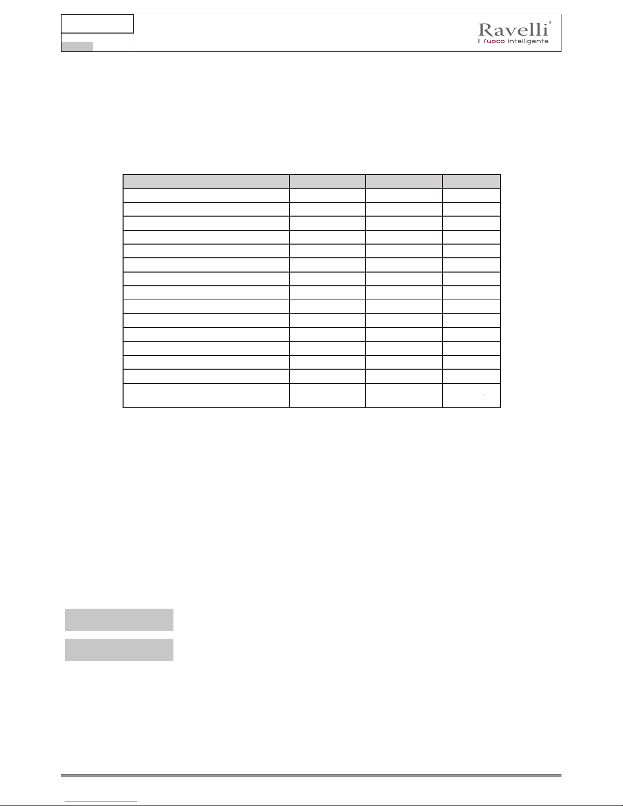
CARATTERISTICHE TECNICHE
Vela 7 Vela 9 U
Ø tubo uscita fumi 80 80 mm
Volume max. di riscaldamento 165 195 m
3
Potenza indotta Rid. - Nom. 3,4 - 7,4 3,4 - 9,1 kW
Potenza resa Rid. - Nom. 3,3 - 6,9 3,3 - 8,3 kW
Consumo orario di pellet Rid. - Nom. 0,71 - 1,53 0,71 - 1,87 kg/h
Potenza elettrica assorbita max. 360 360 W
Alimentazione elettrica 230 - 50 230 - 50 Hz - V
Capacità serbatoio 20 22 kg
Autonomia min. - max. 13 - 28 12 - 28 h
Rendimento Rid. - Nom. 95,5 - 92,9 95,5 - 90,6 %
CO al 13% di O
2
0,018 - 0,004 0,018 - 0,004 %
Portata fumi 2,9 - 4.6 2,9 - 5,7 g/s
Tiraggio minimo 10 - 0,1 10 - 0,1 Pa - mbar
Temperatura dei fumi 73 - 129 73 - 163 °C
Classe di qualità ambientale (secondo il
Decreto n°186 del 7/11/2017 )
4 4
⋆⋆⋆⋆⋆
I dati riportati sono indicativi e non impegnativi e possono variare a seconda del tipo del pellet utilizzato. Ravelli si riserva la facoltà
di apportare qualsiasi modica allo scopo di migliorare le prestazioni dei prodotti.
Caratteristiche del pellet
Il pellet di legno è un combustibile che si compone di segatura di legno pressata, spesso recuperata da scarti di lavorazione delle
falegnamerie. Il materiale impiegato non può contenere alcuna sostanza estranea come ad esempio colla, lacca o sostanze sintetiche.
La segatura, dopo essere stata essiccata e pulita dalle impurità, viene pressata attraverso una matrice a buchi: a causa dell’alta
pressione la segatura si riscalda attivando i leganti naturali del legno; in questo modo il pellet mantiene la sua forma anche senza
aggiunta di sostanze articiali. La densità dei pellet di legno varia a seconda del tipo di legno e può superare di 1,5 - 2 volte quella
del legno naturale.
I cilindretti hanno un diametro di 6 mm e una lunghezza variabile tra 10 e 40 mm.
La loro densità è pari a circa 650 kg/m3. A causa del basso contenuto d’acqua (< 10%) hanno un elevato contenuto energetico.
La norma UNI EN ISO 17225-2:2014 (che sostituisce la norma EN PLUS) denisce la qualità dei pellet denendo tre classi: A1, A2
e B.
Il pellet deve essere trasportato ed immagazzinato in luogo asciutto. Al contatto con l’umidità si gona, diventando quindi inutilizzabile:
pertanto si rende necessario proteggerlo dall’umidità sia durante il trasporto che durante lo stoccaggio. Mantenere il combustibile ad
adeguata distanza.
Ravelli consiglia l’utilizzo di pellet di legno certicato classe A1 e A2 secondo la norma En ISO 17225-2:2014, oppure certcato DIN
PLUS (più restrittiva della classe A1) o ONORM M 7135.
! IMPORTANTE
Utilizzare solo pellet certificato. Il pellet di scarsa qualità può aumentare la velocità di
formazione della patina di sporco sul vetro, aumentare gli interenti di manutenzione.
! IMPORTANTE
Il pellet deve essere trasportato ed immagazzinato in un locale asciutto e privo di umidità.
Combustibili non ammessi
Si raccomanda di non utilizzare come combustibile i seguenti materiali:
• legna da ardere;
• legna trattata (legno verniciato, laccato, incollato, ecc.);
• segatura o trucioli di legno;
• combustibili liquidi;
• carbone o altri combustibili fossili;
• plastica e derivati;
• carta e cartone trattati;
Manuale uso e manutenzione Vela 7-9
Pag.15
Rev.1 20.02.18
ITA
• riuti;
• combustibili che possano sprigionare sostanze tossiche o inquinanti.
L’utilizzo di questi combustibili, oltre che vietato perché provoca l’emissione di sostanze inquinanti e nocive, causa un deterioramento
più rapido della stufa ed un accumulo di sporco nella stufa e nel sistema di evacuazione dei fumi con conseguente decadimento delle
prestazioni e della sicurezza.
I gas prodotti da questi combustibili sono pericolosi per l’ambiente e per la vostra salute!
L’utilizzo di combustibile non conforme a quanto sopra specificato fa decadere la garanzia.
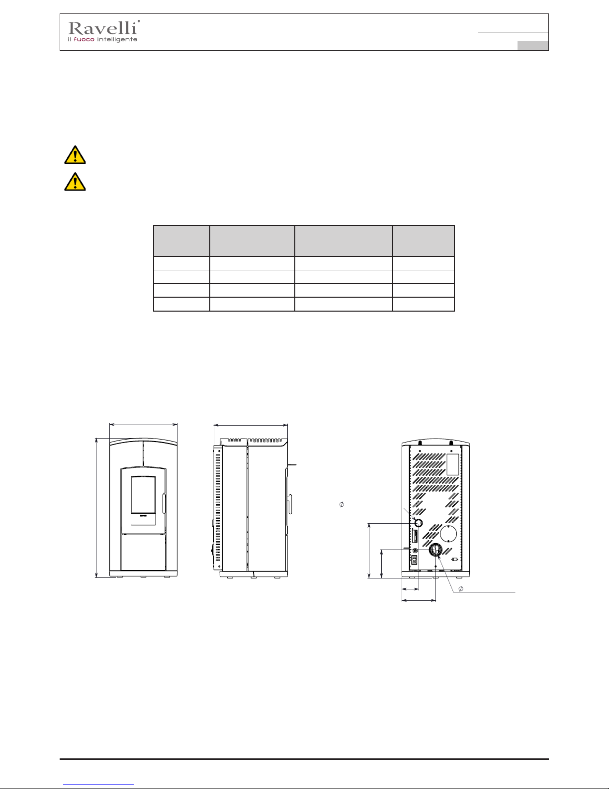
Vela 7 C
Vela 7 N
Vela 7 V
Vela 9 C
Vela 9 N
Vela 9 V
Unità di
misura
Altezza 1060 1109 mm
Larghezza 515 515 mm
Profondità 562 565 mm
Peso a vuoto 185 190 kg
TAVOLA TECNICA VELA 7 N - VELA 7 V
562
216
258
128
419
80 (USCITA FUMI)
50 (ENTRATA ARIA)
515
1060
562
216
258
128
419
80 (USCITA FUMI)
50 (ENTRATA ARIA)

Manuale uso e manutenzione Vela 7-9
Pag.16
Rev.1 20.02.18
ITA
TAVOLA TECNICA VELA 7 C
515
1060
562
216
258
128
419
60 (CANALIZZATA)
50 (ENTRATA ARIA)
80 (USCITA FUMI)
160
337
TAVOLA TECNICA VELA 9 N - VELA 9 V
562
419
216
128
258
50 (ENTRATA ARIA)
80 (USCITA FUMI)
TAVOLA TECNICA VELA 9 C
1109
515
562
216
419
258
128
337
160
60 (CANALIZZATA)
50 (ENTRATA ARIA)
80(USCITA FUMI)
562
216
258
128
419
60 (CANALIZZATA)
50 (ENTRATA ARIA)
80 (USCITA FUMI)
160
337
516
1109
562
419
216
128
258
50 (ENTRATA ARIA)
80 (USCITA FUMI)
562
216
419
258
128
337
160
60 (CANALIZZATA)
50 (ENTRATA ARIA)
80(USCITA FUMI)

Manuale uso e manutenzione Vela 7-9
Pag.17
Rev.1 20.02.18
ITA
Componenti principali
pos. elemento
A Griglia per passaggio
aria
B Porta
C Cassetto cenere
D Sportello serbatoio pellet
E Botola d’ispezione
F Camera di combustione
G Scivolo ceneri
H Braciere
Descrizione del funzionamento
Le stufe a pellet Ravelli sono apparecchi per il riscaldamento domestico alimentati a pellet di legno a caricamento automatico. Sono
apparecchi adatti per essere utilizzati come sistema di riscaldamento secondario o di supporto al sistema di riscaldamento principale.
Il calore generato dalla combustione del pellet viene diffuso nel locale di installazione per irraggiamento e convezione naturale. Nelle
versioni V è possibile scegliere se attivare la ventola frontale oppure mantenere la stufa in funzionamento per convezione naturale.
Nelle versioni C è possibile attivare la canalizzazione per riscaldare un’altra stanza.
La stufa è controllata da una centralina elettronica che gestisce le fasi di accensione, funzionamento e spegnimento e che inoltre
include molte altre funzioni per il controllo, per la programmazione e per la sicurezza.
L’utente può scegliere la potenza di funzionamento tra 5 livelli, oppure impostare la temperatura da mantenere nell’ambiente. In
questo caso sarà la stufa a gestire la potenza per garantire il massimo comfort. Tra le funzioni della centralina elettronica c’è anche
quella di poter programmare l’accensione e lo spegnimento della stufa, impostando il cronotermostato settimanale.
Tutto questo può essere fatto comodamente dal divano utilizzando il telecomando palmare.
Il sistema di pulizia brevettato Ravelli riduce al minimo la manutenzione a cura dell’utente. Non c’è più bisogno di pulire il braciere
prima di ogni accensione e tutte le operazioni di manutenzione.
Questa stufa è stata studiata per installazioni ermetiche, può essere quindi installata in modo tradizionale, oppure prelevando l’aria
direttamente dall’esterno.
A
D
B
C
E
F
H
G

Manuale uso e manutenzione Vela 7-9
Pag.18
Rev.1 20.02.18
ITA
TRASPORTO E INSTALLAZIONE
Avvertenze di sicurezza per il trasporto e l’installazione
! IMPORTANTE
L’installazione della stufa deve essere eseguita da un tecnico qualicato, il quale dovrà
rilasciare all’acquirente una dichiarazione di conformità dell’impianto e si assumerà
l’intera responsabilità dell’installazione e del corretto funzionamento della stufa.
! IMPORTANTE
Il luogo di installazione della stufa deve essere scelto in modo che il calore generato
possa diffondersi uniformemente negli ambienti che si vogliono scaldare.
La stufa deve essere collegata ad una canna fumaria singola che garantisca il tiraggio dichiarato dal Costruttore
e che rispetti le norme di installazione previste nel luogo di installazione.
Il locale dove è installata la stufa deve essere dotato di presa d’aria o di opportuno sistema di approvvigionamento
dell’aria esterna.
La presa d’aria dovrà essere installata in modo tale da non poter essere ostruita.
Il Costruttore declina ogni responsabilità in caso d’installazioni non conformi alle leggi in vigore, di un ricambio aria locali non corretto
e di un uso non appropriato dell’apparecchio.
In particolare è necessario che:
• l’apparecchio sia collegato ad un sistema di evacuazione dei fumi dimensionato opportunamente per garantire il tiraggio
dichiarato dal Costruttore, che sia a tenuta e che rispetti le distanze da materiali inammabili;
• ci sia un’adeguata presa d’aria comburente conforme alla tipologia di prodotto installato o di sistema;
• altri apparecchi a combustione o dispositivi installati non mettano in depressione il locale di installazione della stufa;
• siano rispettate le distanze di sicurezza da materiali inammabili.
La verica di compatibilità dell’impianto precede ogni altra operazione di montaggio o posa in opera.
! IMPORTANTE
Regolamenti amministrativi locali, prescrizioni particolari delle autorità che riguardano
l’installazione di apparecchi a combustione, la presa aria e l’impianto di evacuazione fumi
possono variare in base alla regione o alla nazione. Vericare presso le autorità locali se
esistono delle prescrizioni di legge più restrittive di quanto qui riportato.
Imballo
Una volta ricevuta la stufa e controllare che:
• corrisponda al modello acquistato;
• non presenti danneggiamenti dovuti al trasporto.
Eventuali reclami devono essere comunicati al trasportatore (anche sul documento di accompagnamento), al momento del ricevimento.
Vericare la portata del pavimento prima di movimentare e posizionare la stufa.
Per la movimentazione della stufa con imballo, seguire la procedura sotto descritta:
1 Posizionare le forche del transpallet nelle apposite sedi sotto al bancale di legno.
2 Sollevare lentamente.
3 Portare la stufa vicino al luogo prescelto per l’installazione.
La stufa deve essere sempre movimentata in posizione verticale. Si deve porre particolare attenzione afnché la
porta e il suo vetro siano preservati da urti meccanici che ne compromettono l’integrità
.
Per il disimballo della stufa, seguire la procedura sotto descritta:
1 Tagliare le reggette e rimuovere il telaio di rinforzo in legno appoggiata sulla scatola
2 Sollevare lentamente la scatola di cartone
3 Togliere l’eventuale avvolgimento in pluriball o simili
4 Togliere la stufa dal bancale e posizionare l’apparecchiatura nel luogo prescelto, facendo attenzione che sia conforme
a quanto previsto.
! IMPORTANTE
Lo smaltimento dell’imballo è a cura dell’utente nale, in conformità con leggi vigenti nel
paese d’installazione.

Manuale uso e manutenzione Vela 7-9
Pag.19
Rev.1 20.02.18
ITA
Predisposizioni per il sistema evacuazione fumi
Prestare attenzione alla realizzazione del sistema di evacuazione fumi e rispettare le normative vigenti nel paese
di installazione della stufa.
! IMPORTANTE
Il Costruttore declina ogni responsabilità se imputabili ad un sistema di evacuazione fumi
mal dimensionato e non a norma.
Canali da fumo e raccordi
Con il termine canali da fumo si indicano le tubazioni che collegano l’apparecchio a combustione con la canna fumaria.
Dovranno essere applicate le seguenti prescrizioni:
• rispettare la norma di prodotto EN 1856-2;
• i tratti orizzontali devono avere una pendenza minima del 3% verso l’alto;
• la lunghezza del tratto orizzontale deve essere la minima possibile e la sua proiezione in pianta non superiore a 4 metri;
• i cambi di direzione non devono avere angolo inferiore di 90°(consigliate curve da 45°);
• il numero di cambi di direzione compreso quello per l’introduzione nella canna fumaria, non deve essere superiore a 3;
• la sezione deve essere di diametro costante e uguale dall’uscita del focolare no al raccordo nella canna fumaria;
• è vietato l’uso di tubi metallici essibili ed in brocemento;
• i canali da fumo non devono attraversare locali nei quali è vietata l’installazione di apparecchi a combustione.
In ogni caso i canali da fumo devono essere a tenuta prodotti della combustione e condense, nonché coibentati se passano all’esterno
del locale d’installazione.
Non è ammesso il montaggio di dispositivi di regolazione manuale del tiraggio.
! IMPORTANTE
E’ obbligatorio realizzare un primo tratto verticale di canale da fumo di almeno 1 m per
garantire la corretta espulsione dei fumi.
Canna fumaria
La canna fumaria è un elemento di particolare importanza per il corretto funzionamento della stufa.
La canna fumaria deve essere dimensionata in modo tale da garantire il tiraggio dichiarato dal Costruttore.
Non collegare la stufa ad una canna fumaria collettiva.
.
Nella realizzazione della canna fumaria dovranno essere applicate le seguenti prescrizioni:
• rispettare la norma di prodotto EN 1856-1;
• deve essere realizzata con materiali idonei per garantire la resistenza alle normali sollecitazioni meccaniche, chimiche, termiche
ed avere un’adeguata coibentazione termica al ne di limitare la formazione di condensa;
• avere andamento prevalentemente verticale ed essere priva di strozzature lungo la sua lunghezza;
• essere correttamente distanziata mediante intercapedine d’aria e isolata da materiali inammabili;
• i cambiamenti di direzione devono essere al massimo 2 e di angolo non superiore a 45°;
• la canna fumaria interna all’abitazione deve essere comunque coibentata e può essere inserita in un cavedio purché rispetti le
normative relative all’intubatura;
• il canale da fumo va collegato alla canna fumaria mediante un raccordo a “T” avente una camera di raccolta ispezionabile per il
residuo di combustione e soprattutto per la raccolta della condensa.
! IMPORTANTE
Si raccomanda di verificare nei dati targa della canna fumaria le distanze di sicurezza che
devono essere rispettate in presenza di materiali combustibili e la tipologia di materiale
isolante da utilizzare.
Utilizzare tubazioni a tenuta stagna con guarnizioni siliconiche.
È vietato utilizzare lo scarico diretto a parete o verso spazi chiusi e qualsiasi altra forma di scarico non prevista
dalla normativa vigente nel paese di installazione (Nota Bene: in Italia è consentito solo lo scarico a tetto).
Comignolo
Il comignolo, cioè la parte terminale della canna fumaria, deve soddisfare le seguenti caratteristiche:
• la sezione di uscita fumi deve essere almeno il doppio della sezione interna del camino;
• impedire la penetrazione di acqua o neve;
• assicurare l’uscita dei fumi anche in caso di vento (comignolo anti vento);
• la quota di sbocco deve essere al di fuori della zona di reusso (fare riferimento alle normative nazionali e locali per individuare
la zona di reusso);
• essere costruito sempre a distanza da antenne o parabole, non deve essere mai usato come supporto.

Manuale uso e manutenzione Vela 7-9
Pag.20
Rev.1 20.02.18
ITA
Installazione
Per l’installazione e l’uso dell’apparecchio è necessario rispettare tutte le leggi e i regolamenti locali, nazionali
ed europei.
L’installazione della stufa e la predisposizione delle opere murarie deve rispettare la normativa vigente nel paese
d’installazione (ITALIA = UNI 10683).
! IMPORTANTE
Le operazioni di installazione devono essere eseguite da un tecnico qualicato e/o
autorizzato dal Costruttore. Il personale incaricato dell’installazione dovrà rilasciare
all’acquirente una dichiarazione di conformità dell’impianto, il quale si assumerà l’intera
responsabilità dell’installazione denitiva e del conseguente buon funzionamento del
prodotto installato.
Non vi sarà responsabilità da parte di Ravelli in caso di mancato rispetto di tali precauzioni.
Requisiti del locale di installazione
Il locale di installazione della stufa deve essere sufcientemente ventilato. Per soddisfare questo requisito è necessario dotare il
locale con una presa d’aria comunicante con l’esterno.
! IMPORTANTE
Il locale di installazione deve essere munito di presa d’aria con sezione libera di almeno
100 cm2.
! IMPORTANTE
In caso di installazione in presenza di altri apparecchi di combustione o di impianto di
VMC è necessario vericare il corretto funzionamento dell’apparecchio.
La stufa deve essere collocata all’interno di ambienti abitativi. La stufa non può essere installata in bagno o nelle camere da
letto, a meno che non sia fatta un’installazione ermetica. Il volume del locale di installazione deve essere adeguato alla potenza
dell’apparecchio e comunque superiore a 15 m3.
ATTENZIONE!
I ventilatori di estrazione (esempio: cappe di aspirazione) quando utilizzati nella stessa stanza o spazio della
stufa, possono causare problemi al funzionamento della stufa.
La stufa deve essere installata su un pavimento di adeguata capacità di carico. Se la posizione esistente non
soddisfa questo requisito, occorre prendere misure appropriate (ad esempio utilizzando una piastra per la
distribuzione del carico).
ATTENZIONE!
Prevedere un adeguato isolamento nel caso il piano sia costituito da materiale infiammabile.
Distanza minima da materiali inammabili
R Lato destro 150 mm
L Lato sinistro 150 mm
B Posteriore 100 mm
A Frontale > 800 mm
Se il pavimento su cui è appoggiata la stufa è di materiale inammabile si consiglia un adeguato isolamento. Non possono essere
immagazzinati oggetti e parti sensibili al calore o inammabili in prossimità della stufa; tenere comunque tali oggetti ad una distanza
frontale minima di 100 cm dal punto d’ingombro più esterno dell’apparecchio.
L’installazione della stufa deve garantire facile accesso per la pulizia dell’apparecchio stesso, dei condotti dei gas di scarico e della
canna fumaria.
L AR B

Manuale uso e manutenzione Vela 7-9
Pag.21
Rev.1 20.02.18
ITA
Esempi di installazione
In questo tipo di installazione (g. 1) la canna fumaria deve essere
coibentata.
Il cavedio deve essere ventilato.
Nella parte inferiore della canna fumaria è presente un coperchio di
ispezione opportunamente isolato da vento e pioggia.
Protezione dalla pioggia
Fig.1
Griglia per passaggio aria
nel cavedio con apertura per
ispezione in canna fumaria
Cavedio
Raccordo a T per condensa
Canna fumaria coibentata
All’uscita della stufa non montare una curva a 90°, in quanto la
cenere potrebbe ostruire in poco tempo il passaggio dei fumi,
causando problemi di tiraggio della stufa (vedi Fig. 2).
Cenere depositata nella
curva a 90°
NO
In questo tipo di installazione (Vedi Fig.3) il canale da fumo
(cioè il tratto interno dell’abitazione che collega la stufa la canna
fumaria) non necessita di coibentazione. Per la canna fumaria,
invece è obbligatorio utilizzare una tubazione coibentata. Nella
parte inferiore della canna fumaria è stato montato un raccordo
di tipo “T” con tappo di ispezione; in modo che il tratto esterno
sia ispezionabile. All’uscita della stufa non montare una curva
a 90°, in quanto la cenere potrebbe ostruire in poco tempo il
passaggio dei fumi, causando problemi di tiraggio della stufa
(vedi Fig. 2).
Canale da Fumo:
utilizzo di tubo non
coibentato
Raccordo a T
Canna fumaria coibentata
Fig.3
Protezione dalla pioggia
Raccordo a T per condensa
Camera di raccolta
ceneri di combustione
+ tappo condensa
Presa d’aria
esterna
Presa
d’aria
esterna
Presa
d’aria
esterna

Manuale uso e manutenzione Vela 7-9
Pag.22
Rev.1 20.02.18
ITA
Questo tipo di installazione (Vedi Fig.4) necessita di canna fumaria
coibentata.
Nella parte inferiore della canna fumaria, è stato montato un
raccordo di tipo “T” con tappo di ispezione.
Fig.4
Protezione dalla pioggia
Canna fumaria coibentata
Raccordo a T con
scarico condensa e
camera di raccolta
Questo tipo di installazione (Vedi Fig.5) non necessita di canna
fumaria coibentata, in quanto la canna fumaria è situata all’interno
di una canna fumaria già esistente.
Nella parte inferiore della canna fumaria è stato montato un
raccordo di tipo “T” con tappo di ispezione. È sconsigliato
installare come primo tratto iniziale una curva a 90°, in quanto la
cenere ostruirebbe in poco tempo il passaggio dei fumi, causando
problemi al tiraggio della stufa (Vedi Fig.2).
CANNA FUMARIA INTERNA
Fig.5
Protezione dalla pioggia
Lastra di copertura
Lamiera in acciaio a tenuta stagna
Raccordo a T con camera
di raccolta e per condensa
Botola d’ispezione
Questo tipo di installazione (Vedi Fig.6) necessità di un tratto
orizzontale per collegarsi ad una canna fumaria già esistente.
Rispettare le pendenze indicate in gura, in modo da ridurre il
deposito della cenere nel tratto di tubo orizzontale. Nella parte
inferiore della canna fumaria è stato montato un raccordo di tipo
“T” con tappo di ispezione, così come all’imbocco della canna
fumaria.
È sconsigliato installare come tratto iniziale una curva a 90°, in
quanto la cenere ostruirebbe in poco tempo il passaggio dei fumi,
causando problemi al tiraggio della stufa (Vedi Fig.2).
2 - 3 mt
max
Altezza superiore a 4 mt
Pendenza 3 - 5 %
Max 2 -3 mt
CANNA FUMARIA INTERNA
Fig.6
Raccordo a T per condensa
Botola d’ispezione
Protezione dalla pioggia
Presa
d’aria
esterna
Presa d’aria
esterna
Presa
d’aria
esterna

Manuale uso e manutenzione Vela 7-9
Pag.23
Rev.1 20.02.18
ITA
Collegamenti
! IMPORTANTE
I collegamenti devono essere eseguiti da un tecnico qualicato e/o autorizzato dal
Costruttore.
Collegamento con presa d’aria esterna
La stufa è stata progettata per installazioni ermetiche.
Per eseguire il collegamento con presa d’aria esterna, procedere come descritto di seguito:
passo azione
1
Collegare un tubo di diamentro 50 mm al tubo di ingresso aria comburente nella parte posteriore della stufa.
Nota: il tubo deve essere di lunghezza massima 2 m.
La presa d’aria dovrà essere installata in modo tale da non poter essere ostruita.
Collegamento canna fumaria
La canna fumaria deve essere dimensionata in modo tale da garantire il tiraggio dichiarato dal Costruttore.
La stufa deve essere collegata ad una canna fumaria singola. È vietato collegare la stufa ad una canna fumaria
condivisa con altri apparecchie a combustione o con scarichi di cappe.
Collegamento elettrico
La spina del cavo di alimentazione della stufa deve essere collegata solo dopo la conclusione dell’installazione e dell’assemblaggio
dell’apparecchio, e deve rimanere accessibile dopo l’installazione.
Per eseguire il collegamento elettrico, procedere come descritto di seguito:
passo azione
1 Collegare il cavo di alimentazione sul retro della stufa.
2 Collegare la spina del cavo di alimentazione alla presa di corrente a parete.
Schema elettrico
Schema elettrico KTR AIR (congurazione ventilata o canalizzata singola)
Vers. 03 del 22/03/16
!
"!!
!#
!"
!
$%
!
"
&!
$%
!'
!
&
&!
!'
$
%"!
%"!
M2
M3
S1
R1
S2
G1
nero
rosso
bianco
Schema elettrico Scheda madre
RETE ALIMENTAZIONE 220 V
S3
G4
G5
G2
Scheda OPZIONALE
per gestione
domotica
N
COM
NC
NO
G6
G2
NCG6NOG6C
G6
G5 G5
10 9 8 7 6 5 4 3 2 1
Connessione OPZIONALE per
gestione domotica
Neutro
M4
M5
Fase
M1
bianco
verde
T1
T5
T3
T2
T4
LEGENDA:
Sicurezze
T1- Contatto sportello fuoco
T2- Contatto serbatoio pellet
T3- Sicurezza pellet
T4- Pressostato
T5- Contatto cassetto cenere
Motori
M1- Motoriduttore coclea
M2- Pulitore automatico
M3- Estrattore fumi
M4- Scambiatore (versioni C
e V)
M5- Non presenti
M6- Non presenti
Resistenza
R1- Resistenza
Sonde
S1- Sonda amma (K)
S2- Termostato esterno
S3- Sonda ambiente (opt)
Generico
G1- Debimetro
G2- Encoder lettura giri
estrattore
G3- Palmare “Radio“ Touch
G4- Conta colpi pulitore
automatico
G5- Contatto gestione domotica
G6- Contatto accensione GASSegnalazione allarme uscita
domotica (TRF 39)

Manuale uso e manutenzione Vela 7-9
Pag.24
Rev.1 20.02.18
ITA
Porre attenzione afnchè il cavo di alimentazione (e gli altri eventuali cavi esterni all’apparrecchio) non entrino a
contatto con superfici calde.
Assicurarsi che l’impianto elettrico sia dotato di messa a terra.
Si raccomanda al personale autorizzato di prestare particolare attenzione ai collegamenti elettrici dopo ogni
intervento effettuato sul prodotto.
Collaudo e messa in servizio
La messa in esercizio della stufa deve essere preceduta dal collaudo che prevede la verica di funzionamento dei seguenti elementi:
• collegamento al sistema di evacuazione fumi;
• collegamenti elettrici;
• controllo che tutti i materiali per la costruzione del canale da fumo, canna fumaria, comignolo, siano a norma ed idonei all’uso.
Il collaudo è positivo solo quando tutte le fasi di funzionamento saranno completate senza che siano state rilevate anomalie.
Comandi ed utilizzo
Descrizione del palmare
Il palmare si presenta come nell’immagine seguente:
Le informazioni riportate di seguito vi permetteranno di familiarizzare con il prodotto e di ottenere le migliori prestazioni.
Inserimento delle batterie nel palmare
Togliere il coperchio di protezione delle batterie, posto sul retro del telecomando come in gura A ed Inserire n. 3 batterie (tipo
ministilo AAA 1,5V) nell’alloggiamento del palmare facendo attenzione alla polarità. Rimettere il coperchio di protezione batterie
come in gura B
Il palmare, dopo un prima breve schermata indicante il logo Ravelli, elencherà le lingue disponibili a menu.
Selezionare la lingua desiderata con i tasti di scorrimento e convalidare la selezione con il tasto di conferma.
1
Tasto di incremento “SU” (tasto di
selezione)
2
Tasto di decremento “GIU” (tasto di
selezione)
3
Tasto ON/OFF o ripristino da modalità
“Sleep”
4
Display
5
Tasto di accesso a MENU e ritorno
6
Tasto di conferma
1
2
5
6
4
3
Figura A
Figura B
In modalità “Sleep” lo schermo del
palmare viene oscurato, mantenendo
comunque attiva la comunicazione
radio con la stufa, al ne di ridurre il
consumo delle batterie.

Manuale uso e manutenzione Vela 7-9
Pag.25
Rev.1 20.02.18
ITA
Nel caso di sostituzione delle batterie non è necessario eseguire la procedura di inizializzazione del palmare. In questo caso,
quando il display mostrerà il messaggio “PRIMA INSTALLAZIONE ?”, selezionare NO e premere il tasto di conferma.
Inizializzazione del palmare
Per potere operare correttamente, il palmare necessita di interfacciarsi con la scheda elettronica presente all’interno della stufa.
Per questo motivo il display mostra il seguente messaggio:
Nel caso di primo utilizzo del palmare, scegliere SI con i tasti di selezione e convalidare con il tasto di conferma.
Il display del palmare mostrerà la seguente schermata:
Mantenere premuto per alcuni secondi il tasto di comunicazione radio (RADIO ADJ) della scheda elettronica, posta sulla parte
posteriore della stufa, per inizializzare il palmare.
Il LED giallo lampeggiante indica che la scheda elettronica è in attesa di ricevere il segnale del palmare.
Premendo il tasto di conferma sul palmare, i componenti entrano in comunicazione tra loro. Un segno di spunta sul display,
accompagnato da un segnale acustico, indica che l’operazione di inizializzazione del palmare si è conclusa con successo.
Descrizione del display
Il display del palmare si presenta come di seguito (condizione di stand-by):
2
1
Dopo 5 minuti di inattività, il display del palmare si oscura passando in modalità “SLEEP”, pur mantenendo la connessione
radio con la stufa. Una successiva pressione del tasto ON/OFF riattiva il display.
La prima pressione di un qualsiasi tasto con display attivo accende la sua retroilluminazione, non interpretandolo come un
comando.
4
3
Presa seriale
Presa collegamento cavo palmare
Radio ADJ: pulsante per collegare il palmare
alla scheda
Led di segnalazione
Rosso: allerme attivo
Giallo: In attesa di comunicazione con il
palmare
Verde: Stufa accesa
Tasto di accensione / spegnimento stufa
2
1
3
5
Manuale utente MIA 90
Pag.21
Vers. 1 del 20/10/16
4
32
1 5
Scheda elettronica
Manuale uso e manutenzione Vela 7-9
Pag.26
Rev.1 20.02.18
ITA
Il display si divide in tre parti:
1. Mostra l’attuale temperatura ambiente rilevata dal palmare. La pressione del tasto di scorrimento SU permette di modicare
il set temperatura con i due tasti di scorrimento SU/GIU’. La conferma di ogni variazione avviene in automatico entro 3 secondi
dall’avvenuta modica o per mezzo della pressione del tasto di conferma. Un segnale acustico attesta l’avvenuta variazione.
Icona che indica lo stato della stufa (vedi schema sintetico fasi).
2. Nelle fasi non attive (in abbinamento con la parte 2 del display) indica lo stato della stufa.
Nelle fasi attive indica la potenza di lavoro della stufa. La pressione del tasto di scorrimento GIU’ permette di modicare la potenza,
modicabile con i due tasti di scorrimento SU/GIU’. La conferma di ogni variazione avviene in automatico entro 3 secondi dall’avvenuta
modica o per mezzo della pressione del tasto di conferma. Un segnale acustico attesta l’avvenuta variazione.
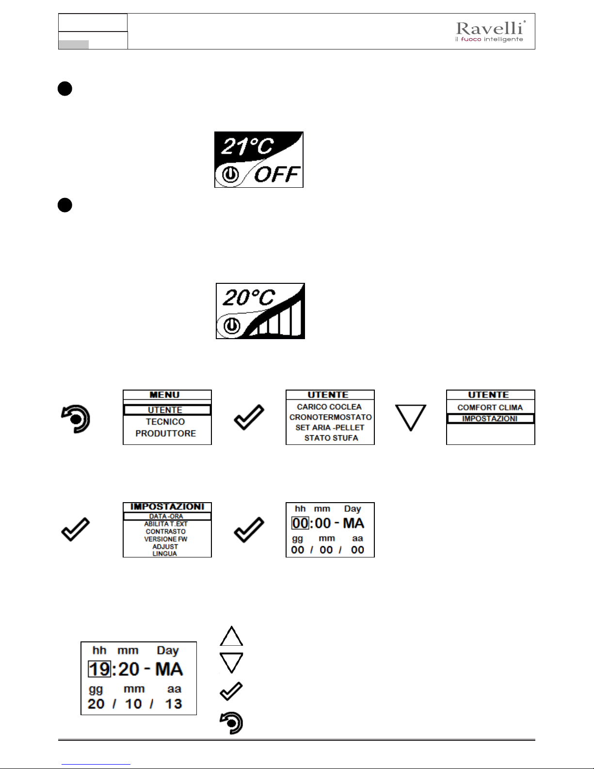
Impostazione della data e dell’ora
Di seguito sono riportati i passi da seguire per accedere al relativo menu.
Pressione del tasto di incremento per modicare ogni singola voce
Pressione del tasto di decremento per modicare ogni singola voce
Pressione del tasto “conferma” per confermare il settaggio e passare
alla voce successiva.
Pressione ripetuta del tasto “ritorno” per visualizzare la schermata di
stand-by.
Pressione del tasto
“conferma”
per accedere alla
schermata UTENTE
Pressione ripetuta del tasto di
“selezione”
per passare alla seconda
schermata di menu UTENTE
e selezionare
IMPOSTAZIONI.
Pressione del tasto
“conferma”
per accedere alla
schermata DATA - ORA
2
1
Pressione del tasto di
“accesso a menu” per
accedere alla
schermata MENU
Pressione del tasto
“conferma” per
accedere alla
schermata
IMPOSTAZIONI
Manuale uso e manutenzione Vela 7-9
Pag.27
Rev.1 20.02.18
ITA
PROCEDURE DI UTILIZZO
In caso di incendio della canna fumaria, chiamare immediatamente i Vigili del Fuoco.
Veriche prima dell’accensione
Assicurarsi di avere letto e compreso perfettamente il contenuto di questo libretto istruzioni.
Prima di eseguire l’accensione della stufa, occorre assicurarsi che:
il serbatoio del pellet sia carico;
• la camera di combustione sia pulita;
• il braciere sia completamente libero, pulito da eventuali residui di combustione e in posizione corretta nella sua sede;
• la chiusura ermetica della porta a fuoco e del cassetto cenere funzionino correttamente;
• la spina elettrica sia collegata correttamente;
• siano stati rimossi tutti gli elementi che potrebbero bruciare (istruzioni, etichette adesive varie).
! IMPORTANTE
Durante le prime ore di utilizzo è possibile che le vernici utilizzate per rinire la stufa
possano emanare un odore sgradevole. Inoltre è possibile sentire l’odore tipico delle
parti metalliche sottoposte a alte temperature. Assicurarsi che sia garantito un sufciente
ricambio d’aria nella stanza. Questi inevitabili sconvenienti spariranno dopo le prime
ore di funzionamento. Per ridurre i disagi al minimo, tenere accesa la stufa per qualche
ora a bassa potenza e nel periodo iniziale non sovraccaricare evitando cicli gravosi di
riscaldamento raffreddamento.
! IMPORTANTE
Durante l’accensione iniziale, la vernice completa la sua essiccazione e si indurisce.
Pertanto, per non rovinarle è sconsigliato toccare le superci verniciate della stufa in
questa fase.
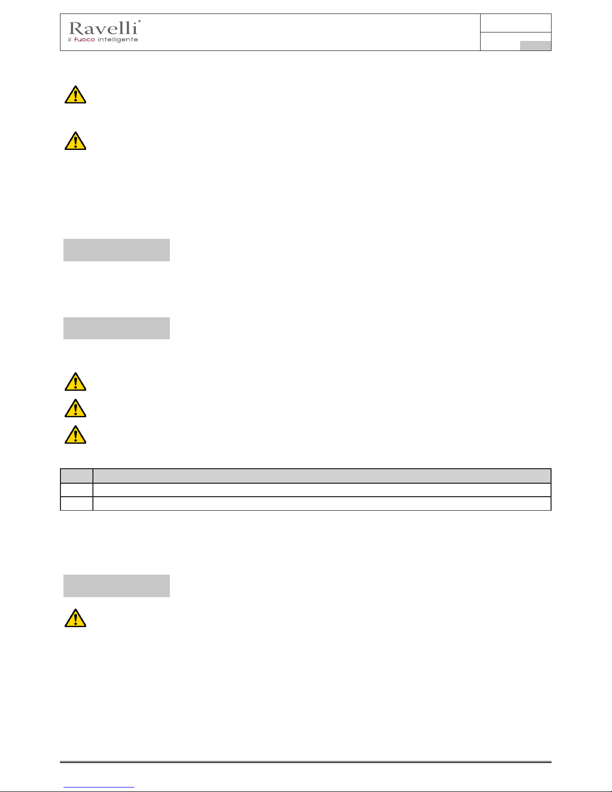
Ricarica del combustibile
Utilizzare solo pellet di legna, delle caratteristiche riportate nel presente manuale.
Il caricamento del pellet deve avvenire a stufa spenta. Nel caso in cui venga eseguita a stufa accesa, l’operazione
dovrà essere conclusa entro 1 minuto altrimenti la stufa si spegnerà.
Durante la fase di ricarica, evitare che il sacco del pellet vada a contatto di superci calde.
Per caricare il pellet all’interno del serbatoio, procedere come descritto di seguito:
passo azione
1 Aprire il coperchio serbatoio pellet (A).
2 Sollevare lo scivolo (B), come mostrato in figura.
Accensione e spegnimento dell’apparecchio
Dalla schermata di “stand-by”, è possibile accendere e/o spegnere la stufa mantenendo premuto il tasto ON/OFF sul palmare per
qualche secondo. Un segnale acustico avvertirà dell’avvenuta accensione o spegnimento dell’apparecchio. In caso non sia possibile
usare il palmare si può accendere/spegnere l’apparecchio utilizzando l’apposito tasto posto sulla scheda elettronica.
! IMPORTANTE
Il braciere viene pulito meccanicamente prima di ogni accensione, tranne che dopo il
carico iniziale coclea ed in caso di riaccensione dopo allarme MANCATA ACCENSIONE
Non spegnere la stufa disconnettendo la spina elettrica dalla presa a parete.
Cosa fare in caso di allarme “Mancata accensione”
Per riaccendere la stufa resettare l’allarme mantenendo premuto il tasto di accensione sul palmare (o sulla scheda elettronica) no
al segnale acustico e ripetere l’accensione.
Non è necessario rimuovere l’eventuale pellet incombusto all’interno del braciere. Infatti, non appena l’utente riavvia la stufa, il
sistema prova ad accendere l’eventuale combustibile rimasto nel braciere prima di avviare la fase di carico.

Manuale uso e manutenzione Vela 7-9
Pag.28
Rev.1 20.02.18
ITA
Carico della coclea
Settaggio della temperatura e della potenza di lavoro:
Impostare i due valori seguendo le indicazioni fornite nel capitolo “Descrizione del display”
Sequenza delle fasi di accensione
ACCENSIONE - fase iniziale di
caricamento pellet;
FASE FIAMMA - fase di attesa
sviluppo della amma; e fase di stabilizzazione amma e riduzione carburante
(pellet) all’interno del braciere;
LAVORO - fase di funzionamento
descritta nel capitolo dedicato;
Pressione del tasto di
“accesso a menu” per
accedere alla
schermata MENU
Pressione del tasto
“conferma”
per accedere alla
schermata UTENTE
Pressione del tasto di
“conferma” per attivare la
rotazione della coclea
In caso di batteria scarica, all’interno
della “goccia” è presente un simbolo
che indica lo stato di limite della stessa, pur mantenendo attive le funzioni
del palmare.
Non appena il livello di batteria non
permette in alcun modo la
comunicazione radio, il palmare
mostra
a schermo intero l’immagine della
batteria scarica, bloccando tutte le
funzioni del palmare no ad avvenuta
sostituzione delle batterie.
Cosa succede in caso di batterie scariche
Prima di effettuare la prima accensione della stufa, tutte le volte che la stufa è in allarme “06 - Pellet esaurito”, e comunque tutte
le volte che la tramoggia si è completamente svuotata, è necessario effettuare il carico iniziale della coclea. Questa fase serve a
riempire il sistema di caricamento del pellet in modo che al momento dell’accensione il sistema sia pronto a caricare il pellet nel
braciere.
Nel caso in cui non si eseguono le operazioni di carico coclea, si potrebbero vericare episodi di mancata accensione della stufa.
IL TEMPO PREIMPOSTATO DEL CARICO INIZIALE È TALE DA COMPRENDERE ANCHE IL PELLET SUFFICIENTE
AD EFFETTUARE LA PRIMA ACCENSIONE. DOPO IL CARICO INIZIALE, QUINDI, NESSUNA PULIZIA BRACIERE
PRECEDERÀ LA FASE DI ACCENSIONE.
Accensione e spegnimento dell’apparecchio
Dalla schermata di “stand-by”, è possibile accendere e/o spegnere la stufa mantenendo premuto il tasto ON/OFF sul palmare per
qualche secondo. Un segnale acustico avvertirà dell’avvenuta accensione o spegnimento dell’apparecchio. In caso non sia possibile
usare il palmare si può accendere/spegnere l’apparecchio utilizzando l’apposito tasto posto sulla scheda elettronica.
La comparsa del messaggio “REGOLARE SISTEMA RDS” indica che la procedura iniziale di collaudo e taratura dei
parametri non è stata effettuata correttamente. Questa indicazione non implica il blocco della stufa (vedi sezione POP UP
DI SEGNALAZIONE).
Nei modelli con braciere autopulente, il braciere viene pulito meccanicamente prima di ogni accensione, tranne che
dopo il carico iniziale coclea ed in caso di riaccensione dopo allarme MANCATA ACCENSIONE.

Manuale uso e manutenzione Vela 7-9
Pag.29
Rev.1 20.02.18
ITA
Fasi di funzionamento dell’apparecchio
Durante la fase di lavoro, quando il set temperatura ambiente è stato raggiunto la stufa passa in modalità MODULA, fase in cui il
consumo di combustibile è minimo.
La modulazione
Qualora si volesse rilevare la temperatura ambiente per mezzo di un termostato esterno (optional), questo dovrà essere
collegato nell’apposito connettore posto sul lato posteriore della stufa; si dovrà pertanto attivare la lettura nell’apposito
menu “IMPOSTAZIONI - ABILITA TERMOSTATO”. A display comparirà la scritta TON / TOFF in base alla richiesta del
termostato.
COLLEGARE UN TERMOSTATO ESTERNO CHE ABBIA UN CONTATTO APERTO/CHIUSO PERTANTO NON IN
TENSIONE. INOLTRE SI CONSIGLIA UN TERMOSTATO CON OFFSET DI ALMENO 3°C SE SI DESIDERA UTILIZZARE
LA FUNZIONE COMFORT CLIMA.
L’attivazione di questa funzione permette alla stufa, una volta raggiunta la temperatura ambiente desiderata, di spegnersi. Appena il
set temperatura è raggiunto la stufa passa in modalità modula. Successivamente verica che la temperatura sia mantenuta per un
periodo di tempo stabilito, e se ciò avviene, si spegne automaticamente, mostrando a display la scritta ECO.
La stufa si riaccende quando la temperatura scende al di sotto della soglia impostata.
Di seguito sono riportati i passi da seguire per accedere al relativo menu.
Comfort clima
Pressione del tasto di
“accesso a menu” per
accedere alla
schermata MENU
Pressione del tasto
“conferma”
per accedere alla
schermata UTENTE
Pressione ripetuta del tasto di
“selezione”
per passare alla seconda
schermata di menu UTENTE
e selezionare
COMFORT CLIMA.
Una volta effettuato l’accesso al menu Comfort clima è possibile operare sulle impostazioni dedicate alla funzione:
Premere ripetutamente il tasto no al ritorno della schermata di Stand-by.

Manuale uso e manutenzione Vela 7-9
Pag.30
Rev.1 20.02.18
ITA
La prima impostazione permette l’attivazione della funzione COMFORT CLIMA; questa funzione ha lo scopo di vericare che la
temperatura impostata all’ambiente venga mantenuta al settaggio impostato per un periodo massimo di “X” minuti (RITARDO
SPEGNIMENTO: 5 MIN) prima di passare alla fase di ECO STOP. La STUFA mantiene questo stato no a quando la temperatura
dell’ambiente scende al di sotto del valore impostato (DELTA COMFORT CLIMA: 5°C).
Ad esempio, con un set ambiente di 21°C, la stufa si spegne al suo raggiungimento, per ripartire quando viene rilevata una
temperatura di 16°C (21°C - 5°C).
E’ possibile attivare la funzione anche utilizzando un termostato esterno, in questo caso non viene considerato il valore di DELTA
COMFORT CLIMA.
Descrizione delle funzioni a menu
Pressione del tasto per accedere alla schermata dei MENU
I menu TECNICO e PRODUTTORE sono protetti da password d’accesso.
La modica di parametri all’interno di questi menù potrebbe compromettere il funzionamento e la sicurezza della stufa.
In questo caso la garanzia viene invalidata.
Con la funzione Cronotermostato è possibile programmare per ogni giorno della settimana l’accensione e lo spegnimento
automatico della stufa in 4 intervalli temporali indipendenti (IMPOSTA CRONO 1-2-3-4)
Di seguito sono riportati i passi da seguire, partendo dalla schermata di Stand-By, per accedere al relativo menu.
Cronotermostato
Pressione del tasto di
“accesso a menu” per
accedere alla
schermata MENU
Pressione del tasto
“conferma”
per accedere alla
schermata UTENTE
Pressione del tasto di
“selezione”
per passare alla voce
CRONOTERMOSTATO.
Pressione dei tasti di
“incremento/decremento”
per modicare la ventilazione.
Pressione del tasto
“conferma” al termine delle
impostazioni della seguente
pagina di CRONO
Per uscire dalla schermata e tornare alla schermata di Stand-By, premere ripetutamente il tasto.
Il tasto di uscita riporta al menu CRONO per poter impostare le altre variabili di funzione relative al menu.

Manuale uso e manutenzione Vela 7-9
Pag.31
Rev.1 20.02.18
ITA
Di seguito sono riportati i passi da seguire, partendo dalla schermata di Stand-By, per accedere al relativo menu.
Stato Stufa
Pressione del tasto di
“accesso a menu” per
accedere alla
schermata MENU
Pressione del tasto
“conferma”
per accedere alla
schermata UTENTE
Pressione del tasto di
“selezione”
per passare alla voce
STATO STUFA.
Per uscire dalla schermata STATO STUFA e tornare alla schermata di Stand-By, premere ripetutamente il tasto.
In questo menu si potrà vericare il corretto funzionamento dei parametri più importanti dell’apparecchio. Di seguito si riporta un
elenco di dati reali della stufa utili al servizio di assistenza durante le fasi di controllo.
- Giri estrattore;
- Temperatura amme;
- Temperatura scheda elettronica;
- Stato stufa
Di seguito sono riportati i passi da seguire, partendo dalla schermata di Stand-By, per accedere al relativo menu.
Impostazioni > Abilita termostato
Pressione del tasto di
“accesso a menu” per
accedere alla
schermata MENU
Pressione del tasto
“conferma”
per accedere alla
schermata UTENTE
Pressione del tasto di
“selezione” per passare alla
seconda pagina del menù
alla voce
IMPOSTAZIONI.
Pressione del tasto
“conferma” per
accedere alla
schermata
IMPOSTAZIONI
Pressione del tasto di
“selezione” per passare
alla voce
ABILITA TERMOSTATO.
Pressione del tasto
“conferma”
per accedere alla funzione
Pressione del tasto
“conferma”
per abilitare la funzione
In stato di Stand-By, al posto della temperatura ambiente
rilevata ed impostabile, compare la stringa T ON se la
stanza in cui è installato il termostato non ha ancora
raggiunto la temperatura richiesta, oppure la scritta T OFF
se nella stanza la temperatura ambiente viene raggiunta.
Pressione ripetuta del
tasto per tornare alla
schermata di
“STAND-BY”
RPM
T
Tsk
g/min
°C
°C

Manuale uso e manutenzione Vela 7-9
Pag.32
Rev.1 20.02.18
ITA
Di seguito sono riportati i passi da seguire, partendo dalla schermata di Stand-By, per accedere al relativo menu.
Impostazioni
Pressione del tasto di
“accesso a menu” per
accedere alla
schermata MENU
Pressione del tasto
“conferma”
per accedere alla
schermata UTENTE
Pressione del tasto di
“selezione” per passare alla
seconda pagina del menù
alla voce
IMPOSTAZIONI.
Pressione del tasto
“conferma” per
accedere alla
schermata
IMPOSTAZIONI
Pressione del tasto di
“selezione” per passare
alla voce
VERSIONE FW.
Pressione del tasto
“conferma”
per accedere alla funzione
Dopo aver seguito passo passo la procedura riportata sopra, si possono impostare le seguenti funzioni:
Impostazioni > Contrasto
Pressione del tasto di
“selezione” per passare
alla voce
ADJUST.
Pressione del tasto
“conferma”
per accedere alla funzione
Per accedere alla seguente impostazione, seguire gli stessi passi riportati in precedenza o piu semplicemente togliere e rimettere
le batterie, il palmare si resetta e domanda nuovamente la lingua che si desidera impostare.
Impostazioni > Lingua
Pressione del tasto
“conferma” per
accedere alla
schermata
IMPOSTAZIONI
Pressione del tasto di
“selezione” per passare
alla voce
CONTRASTO.
Pressione del tasto
“conferma”
per accedere alla funzione
Per mezzo dei tasti “SU” e “GIU” è possibile variare
l’impostazione del contrasto al ne di una migliore
visualizzazione delle informazioni presenti sul palmare.
Il valore può variare da 0 a 100. 50 è il valore standard.
La pressione del seguente tasto permette la conferma
del dato ed il passaggio alla schermata all’interno del
menù IMPOSTAZIONI.
Impostazioni > Versione rmware
La pressione del seguente tasto permette la conferma del dato ed il passaggio alla schermata all’interno del menù
IMPOSTAZIONI.
Impostazioni > Adjust
Per mezzo dei tasti “SU” e “GIU” è possibile effettuare
una variazione al valore letto dalla sonda ambiente
presente all’interno del palmare rispetto ad un valore di
riferimento. Il valore può variare da -10°C a 10°C.
Il valore standard è 0°C.
La pressione del seguente tasto permette la conferma
del dato ed il passaggio alla schermata all’interno del
menù IMPOSTAZIONI.

Manuale uso e manutenzione Vela 7-9
Pag.33
Rev.1 20.02.18
ITA
Le stufe con ventola opzionale sfruttano il sistema a convezione naturale che garantisce un notevole apporto di calore in ambiente
con la totale assenza di rumore dato dalla ventilazione ambiente. Esiste comunque la possibilità, mediante l’accesso al menu di
seguito riportato, di attivare la ventilazione opzionale secondo la potenza da voi richiesta.
Di seguito sono riportati i passi da seguire, partendo dalla schermata di Stand-By, per accedere al relativo menu.
Pressione del tasto di
“accesso a menu” per
accedere alla
schermata MENU
Pressione del tasto
“conferma”
per accedere alla
schermata UTENTE
Pressione del tasto di
“conferma”
per passare alla voce
VENTILAZIONE.
Per uscire dalla schermata e tornare alla schermata di Stand-By, premere ripetutamente il tasto.
Gestione ventilazione (funzione presente solo per i modelli canalizzati e ventilati)
Gestione: si può impostare la velocità di ventilazione o canalizzazione a 0 (disattivata) l’impostazione da 1 a 5 permette la scelta
della velocità di propagazione del calore. Se impostato il valore in AUTO, la ventilazione segue la potenza impostata della stufa.
Se non viene impostata la funzione AUTO, la ventola risulta svincolata dalla potenza della stufa, ad esclusione di quando
la amma passa in modulazione che in cui lo scambiatore si porta al minimo.
Pressione dei tasti di
“incremento/decremento”
per modicare la ventilazione.

Manuale uso e manutenzione Vela 7-9
Pag.34
Rev.1 20.02.18
ITA
Schema sintetico fasi della stufa
FASE DESCRIZIONE
PULIZIA FINALE
La stufa è in fase di spegnimento e non è ancora terminata la fase di raffreddamento.
ACCENSIONE
E’ stata avviata la fase di preriscaldo resistenza, ed il pellet comincia a cadere nel braciere.
FASE FIAMMA
Il pellet si accende sfruttando il calore dell’aria in ingresso che passa per il condotto della
resistenza incandescente.
Nel braciere è visibile la amma.
LAVORO
La stufa ha terminato la fase di accensione e si porta alla potenza di lavoro impostata.
LAVORO MODULA
E’ stato raggiunto il settaggio della temperatura ambiente desiderato.
PULIZIA BRACIERE
E’ attiva la fase di pulizia periodica del braciere: per qualche secondo viene ridotto il carico
del pellet ed aumentata l’aria.
ECO STOP
Con Comfort Clima attivato la stufa passa in condizione di spegnimento automatico al
raggiungimento del settaggio ambiente impostato (vedi paragrafo relativo).
ATTESA AVVIO/RIAVVIO
E’ richiesta un’accensione ma con stufa in fase di raffreddamento; raggiunta tale condizione
parte automaticamente.
ACCENDI RIAVVIO
E’ stata avviata la fase di riaccensione a caldo.
Il funzionamento è analogo alla fase ACCENSIONE.
HOT FUMI
E’ stata raggiunta la soglia massima di temperatura dei fumi; per facilitare il raffreddamento,
la stufa si porta al minimo con ventilazione a potenza 5 permettendo il calo della
temperatura dei fumi.
SPENTO
La stufa è spenta
ATTESA TERMINE
PELLET
Quando la richiesta di accensione da uno stato di ECO-STOP si sovrappone ad una
condizione di spegnimento automatico (da TIMER), la stufa si accende assicurando la
totale pulizia del braciere prima di passare in PULIZIA FINALE.
CARICO COCLEA
ECCESSIVO
CONDIZIONE: l’impostazione del pellet (set pellet +5) è prossima alla condizione di carico
in continuo.
SOLUZIONE: Portare il settaggio nuovamente a 0.
ALLARME (generico) La stufa si trova in stato di allarme, consultare capitolo relativo agli allarmi.

Manuale uso e manutenzione Vela 7-9
Pag.35
Rev.1 20.02.18
ITA
Pop Up di segnalazione
ANOMALIA DESCRIZIONE
RICHIESTA SERVICE
E’ stata raggiunta la soglia di ore lavoro impostata. Il simbolo che appare resta sempre
attivo in fase di lavoro. Si consiglia di richiedere la manutenzione straordinaria della stufa.
Allarmi (tabella codici di riferimento)
COD. TITOLO MOTIVAZIONE RISOLUZIONE
AL 01 BLACK OUT
- Mancata tensione durante la fase di lavoro - Premere il tasto di spegnimento e ripetere
l’accensione della stufa
- Se il problema persiste rivolgersi al Servizio di
Assistenza.
AL 02 SONDA FUMI/FIAMMA
- La sonda fumi/amma è malfunzionante - Rivolgersi al Servizio di Assistenza
- La sonda fumi/amma è scollegata dalla scheda
elettronica
- Rivolgersi al Servizio di Assistenza
AL 03 SOVRATEMP. FUMI
- La combustione nel braciere non è ottimale a
causa di sovraccarico oppure a causa di aperture
di areazione ostruite.
- Spegnere la stufa, regolare la
combustione con il settaggio del Pellet/Aria e
disostruire le aperture di areazione.
- Se il problema persiste rivolgersi al Servizio di
Assistenza.
AL 04 ESTRATTORE GUASTO
- Encoder estrattore fumi non funzionante o non
collegato in modo corretto
- Rivolgersi al Servizio di Assistenza
- Manca alimentazione all’estrattore dei fumi - Rivolgersi al Servizio di Assistenza
-
L’estrattore fumi è bloccato
- Rivolgersi al Servizio di Assistenza
AL 05 MANCATA ACCENSIONE
-
Il serbatoio del pellet è vuoto
- Vericare la presenza di pellet nel serbatoio.
Eventualmente caricarlo.
- Taratura del pellet e dell’aspirazione in fase di
accensione inadeguata.
- Rivolgersi al Servizio di Assistenza
- La resistenza per l’accensione è difettosa o non
in posizione
- Rivolgersi al Servizio di Assistenza
AL 06 PELLET ESAURITO
- Il serbatoio del pellet è vuoto. - Vericare la presenza di pellet nel serbatoio.
Eventualmente caricarlo
- Il motoriduttore non carica pellet - Svuotare il serbatoio per vericare che
all’interno non siano caduti oggetti che
potrebbero impedire il corretto funzionamento
della coclea.
- Carenza di carico pellet -
Regolare il set del pellet da “SET ARIA/PELLET”
- Se il problema persiste, rivolgersi al Servizio di
Assistenza
AL 07
TERMICO A RIARMO / PORTA,
CASSETTO O SPORTELLO PELLET
APERTO
- E’ intervenuto il termostato a riarmo manuale
collegato alla tramoggia (TERMICO A RIARMO).
- Riarmare il termostato premendo il pulsante sul
retro della stufa oppure. .
- Porta, cassetto o sportello pellet sono rimasti
aperti.
- Chiudere gli sportelli
- Rivolgersi al Servizio di Assistenza
AL 08 DEPRESSIONE
- La canna fumaria è ostruita. - Vericare che la canna fumaria sia libera e
pulita.
- Il vacuostato è malfunzionante. - Rivolgersi al Servizio di Assistenza
AL 12 ANOMALIA GIRI ESTRATTORE
- I
giri dell’estrattore fumi presentano una perdita di
efficienza dovuta all’ostruzione della ventola o ad
un calo di tensione.
- Rivolgersi al Servizio di Assistenza
AL 14 FASE COCLEA
- Mancato collegamento del cablaggio che porta
alimentazione al motoriduttore della coclea
- Rivolgersi al Servizio di Assistenza
ANOMALIA (generica)
La stufa ha segnalato un’anomalia, consultare capitolo relativo alle anomalie.
SISTEMA PULITORE
AUTOMATICO ATTIVO
Il pulitore automatico del braciere è attivo.

Manuale uso e manutenzione Vela 7-9
Pag.36
Rev.1 20.02.18
ITA
AL 15 TRIAC COCLEA
- Anomalia ad un componente interno alla scheda
elettronica che gestisce la coclea di caricamento
pellet
- Rivolgersi al Servizio di Assistenza
- Possibili cali di tensione o tensione errata in
ingresso alla stufa
-
Controllare la tensione di alimentazione.
AL 19
GUASTO PULITORE
(per modelli con pulitore)
- Il pulitore non ha completato la movimentazione
e non si trova nella posizione corretta oppure lo
sportello fuoco non è chiuso correttamente.
- Controllare se lo sportello è chiuso
correttamente e Resettare l’allarme ed
attendere che la stufa si portI in stato di
SPENTO. Togliere e rimettere corrente, il
sistema riattiva il pulitore cercando
nuovamente la posizione corretta.
- Se il problema persiste, contattare il Servizio di
Assistenza
Posizione dell’interruttore,
protetto dal cappuccio
avvitabile, del termostato a
riarmo di sicurezza posto sul
retro della stufa.

Manuale uso e manutenzione Vela 7-9
Pag.37
Rev.1 20.02.18
ITA
MANUTENZIONE
Avvertenze di sicurezza per la manutenzione
La manutenzione della stufa deve essere effettuata almeno una volta all’anno, e programmata per tempo con il
Servizio di Assistenza Tecnica.
In alcune condizioni, come accensione, spegnimento o utilizzo inappropriato, i prodotti della combustione
possono contenere piccole particelle di fuliggine che si accumulano nel sistema di evacuazione fumi. Ciò può
ridurre la sezione di passaggio dei fumi e comportare un rischio di incendio. Il sistema di evacuazione fumi deve
essere ispezionato e pulito almeno una volta all’anno.
Le operazioni di manutenzione devono essere eseguite a stufa fredda e con alimentazione elettrica disconnessa.
Prima di effettuare qualsiasi operazione di manutenzione, adottare le seguenti precauzioni:
• Accertarsi che la spina dell’alimentazione elettrica sia scollegata.
• Accertarsi che tutte le parti della stufa siano fredde.
• Accertarsi che le ceneri siano completamente fredde.
• Operare sempre con attrezzature approppriate per la manutenzione.
• Terminata la manutenzione reinstallare tutte i dispositivi di sicurezza prima di rimetterla in servizio.
! IMPORTANTE
La qualità del pellet, le modalità di utilizzo della stufa e la regolazione della combustione
possono inuenzare la frequenza degli interventi di manutenzione.
Pulizia
! IMPORTANTE
Eseguire le operazioni di pulizia in modo da garantire il corretto funzionamento della stufa.
Nella seguente tabella vengono elencati gli interventi di pulizia necessari per il corretto
funzionamento della stufa.
PARTI / FREQUENZA 1 GIORNO 2-3 GIORNI 30 GIORNI 60-90 GIORNI 1 STAGIONE
Cassetto cenere
•
Vetro
•
Condotto aspirazione
•
Raschiatore fascio tubiero
•
Camera di combustione
•
Aspirare serbatoio pellet
•
Pulizia del vetro
A stufa fredda, pulire il vetro con uno straccio ed un detergente per vetri.
Nota: in commercio si trovano appositi detergenti per i vetri delle stufe.
Sistema di pulizia automatico
La stufa è dotata di sistema di pulizia atuomatica del braciere. Questo permette di non dover effettuare la pulizia manuale quotidiana
del braciere o ad ogni accensione della stufa. Il sistema di pulizia automatica si attiva ad ogni accensione della stufa e dopo 6 ore di
funzionamento continuo. Il ciclo di pulizia, che prevede lo spegnimento, la pulizia automatica e la riaccensione della stufa, avviene in
circa 10 minuti. Durante questo periodo il riscaldamento è garantito dal calore accumulato dall’apparecchio stesso.
Nota: le tempistiche indicate sono quelle impostate di default dal Costruttore.
Pulitore in funzione (rotazione di
360°)
Vista del cassetto cenere dove il braciere
rilascia il residuo di combustione

Manuale uso e manutenzione Vela 7-9
Pag.38
Rev.1 20.02.18
ITA
! IMPORTANTE
IL PULITORE SI ATTIVA AD OGNI ACCENSIONE DELLA TERMOSTUFA (2 ROTAZIONI DI DEFAULT)
E DOPO 6 ORE (VALORE DEFAULT) DI FUNZIONAMENTO CONTINUO DELLA MEDESIMA. IL CICLO
DI SPEGNIMENTO E RIACCENSIONE DELLA TERMOSTUFA DURANTE LA FASE DI PULIZIA CON
PULITORE AVVIENE IN CIRCA 10min. TRATTANDOSI DI STUFE CON SCAMBIATORE IN GHISA,
LA PROPAGAZIONE DEL CALORE VIENE OTTIMAMENTE GARANTITA PER TUTTO IL PERIODO DI
PULIZIA E RIACCENSIONE DELL’APPARECCHIO STESSO.
Pulizia del cassetto cenere
La pulizia del cassetto cenere deve essere effettuata ogni 30 giorni (in relazione dal tempo di utilizzo della stufa e al tipo di pellet
utilizzato).
Per eseguire la pulizia del cassetto cenere, procedere come descritto di seguito:
Pulizia della camera di combustione
Per eseguire la pulizia della camera di combustione, procedere come descritto di seguito:
passo azione
1
Aspirare i residui presenti in camera di combustione con un aspiracenere apposito, assicurandosi che le ceneri siano
completamente spente.
1
2
Camera di combustione
Scivolo ceneri

Manuale uso e manutenzione Vela 7-9
Pag.39
Rev.1 20.02.18
ITA
Pulizia del serbatoio pellet
Per eseguire la pulizia del serbatoio pellet, procedere come descritto di seguito:
passo azione
1 Rimuovere periodicamente la segatura di legno accumulata sul fondo del serbatoio, utilizzando un aspiratore.
Pulizia condotto fumi
! IMPORTANTE
Questa operazione deve essere svolta da un Centro Assistenza Ravelli.
Programmare con il Centro Assistenza Ravelli questo tipo di pulizia.
La pulizia del condotto fumi deve essere effettuata ogni 3 mesi (ogni 2500 ore).
La stufa è dotata di alcune botole per la pulizia dei condotti fumo interni.
Per effettuare la pulizia dei condotti fumo, procedere come descritto di seguito:
passo azione
1 Aprire le botole.
2 Aspirare le ceneri, eventualmente utilizzare uno scovolo o simili e rimontare il tutto.
Nota: le botole sono dotate di guarnizione pertanto prima di rimontarle, assicurarsi che le guarnizioni non siano usurate.
Nota: L’operazione deve essere effettuata a stufa fredda, utilizzando un aspiratore di tipo aspira cenere.
Manutenzione straordinaria
Le operazioni di manutenzione straordinaria devono essere eseguite da personale del Centro di Assistenza
Autorizzato.
Non attendere che i componenti siano logorati dall’uso prima di procedere alla loro sostituzione. Sostituire
un componente usurato prima che sia completamente rotto per prevenire eventuali danni causati dalla rottura
improvvisa dei componenti.
PARTI/ FREQUENZA 60- 90 GIORNI 1 STAGIONE
Pulizia approfondita camera di combustione
•
Guarnizione porta
•
Canna fumaria
•
1
BOTOLA ISPEZIONE
GUARNIZIONE

Manuale uso e manutenzione Vela 7-9
Pag.40
Rev.1 20.02.18
ITA
Pulizia approfondita della camera di combustione
! IMPORTANTE
Questa operazione deve essere svolta da un Centro Assistenza Ravelli.
Programmare con il Centro Assistenza Ravelli questo tipo di pulizia.
Programmare con il Centro di Assistenza Autorizzato gli interventi di manutenzione straordinaria sopra indicati.
Per effettuare la pulizia della camera di combustione, procedere come descritto di seguito:
1 Rimuovere il fermo della vermiculite.
2 Rimuovere la vermiculite.

Manuale uso e manutenzione Vela 7-9
Pag.41
Rev.1 20.02.18
ITA
STOCCAGGIO E SMALTIMENTO
Smaltimento
La demolizione e lo smaltimento della stufa è ad esclusivo carico e responsabilità del proprietario che dovrà agire in osservanza delle
leggi vigenti nel proprio Paese in materia di sicurezza, rispetto e tutela dell’ambiente.
Alla ne della sua vita utile, il prodotto non deve essere smaltito insieme ai riuti urbani. Può essere consegnato presso gli appositi
centri di raccolta differenziata predisposti dalle amministrazioni comunali, oppure presso i rivenditori che forniscono questo servizio.
Smaltire in modo differenziato il prodotto consente di evitare possibili conseguenze negative per l’ambiente e per la salute derivanti
da un suo smaltimento inadeguato e permette di recuperare i materiali di cui è composto al ne di ottenere un importante risparmio
di energia e di risorse.
CASISTICA GUASTI
La stufa non funziona
• seguire attentamente quello che è riportato nel capitolo dedicato di questo manuale.
• controllare che il condotto di ingresso dell’aria non sia ostruito;
• controllare che il sistema di evacuazione fumi sia pulito e non ostruito;
• controllare che la canna fumaria sia adeguata alla potenza della stufa;
• controllare che la presa d’aria nella stanza sia libera da ostruzioni e che non ci siano altri apparecchi a combustione o cappe di
aspirazione che mettano in depressione la stanza;
Accensione difcoltosa
• seguire attentamente quello che è riportato nel capitolo dedicato di questo manuale;
• controllare che il condotto di ingresso dell’aria non sia ostruito;
• controllare che il sistema di evacuazione fumi sia pulito e non ostruito;
• controllare che la canna fumaria sia adeguata alla potenza della stufa.
• controllare che la presa d’aria nella stanza sia libera da ostruzioni e che non ci siano altri apparecchi a combustione o cappe di
aspirazione non mettano in depressione la stanza.
Perdita di fumo
• Controllare il tiraggio della canna fumaria.
• Controllare che le guarnizioni sulla porta, sul cassetto e del sistema di evacuazione fumi siano integre.
• Controllare che la cenere non ostruisca la griglia di passaggio aria primaria.
Il vetro si sporca facilmente
• Utilizzare solo combustibili raccomandati.
• Controllare il tiraggio della canna fumaria.
Messa a riposo (ne stagione)
A ne di ogni stagione si consiglia di aspirare eventuali residui di cenere e polveri al suo interno. Si consiglia, inoltre, di lasciar
terminare il pellet nel serbatoio per provvedere ad aspirare i resti di pellet e segatura dal fondo del serbatoio e dalla coclea.
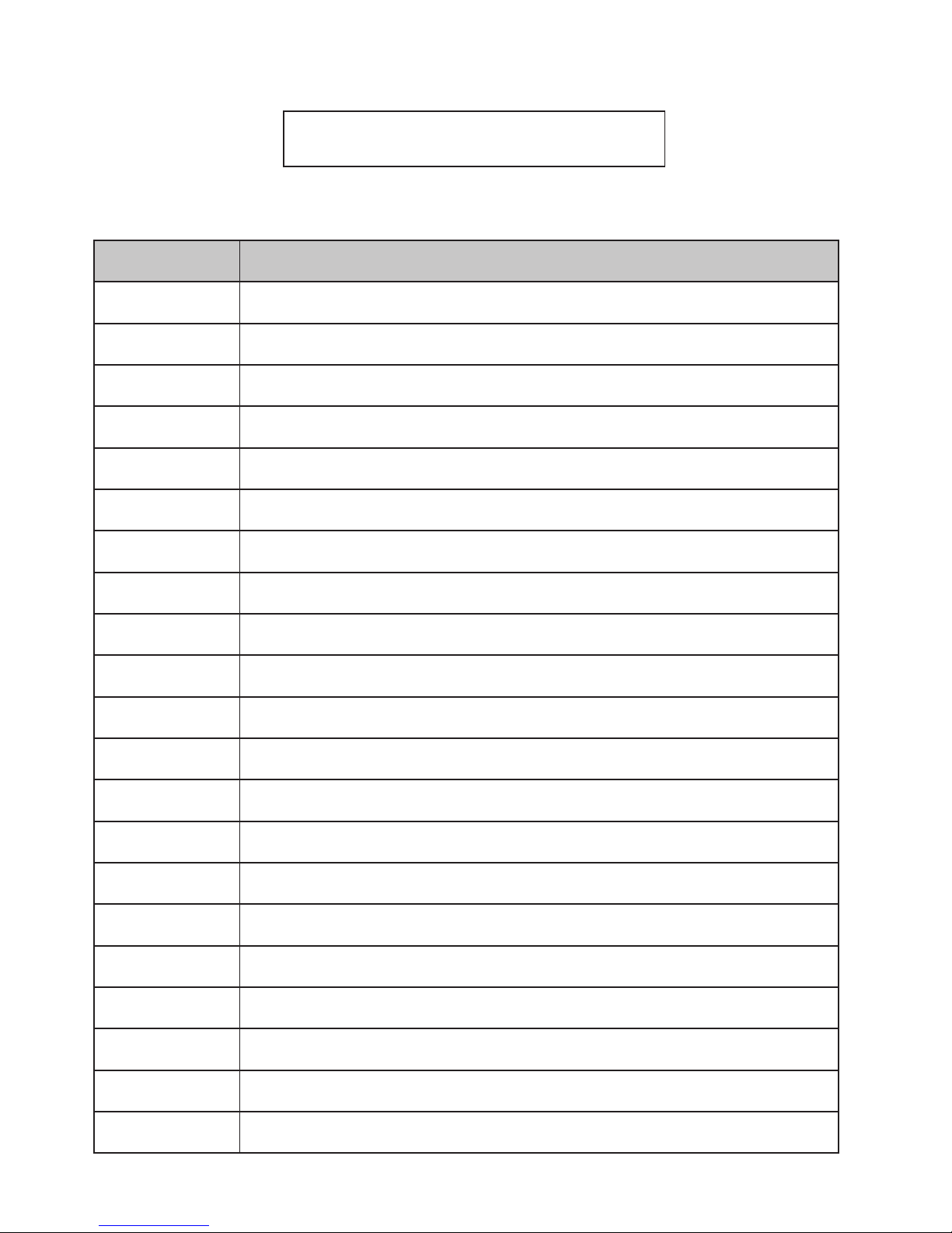
DATA INTERVENTO EFFETTUATO
MANUTENZIONE

Preface
Dear Customer, We would like to thank you for choosing one of our stoves.
We invite you to read this manual carefully, before starting installation and use, so that you are able to benet from all of its
characteristics better and in full safety. It contains all necessary information for correct installation, start-up, operation, cleaning,
maintenance, etc.
Keep this manual in a suitable location, do not discard it without reading it.
Incorrect installation, maintenance and improper use of the product relieve the Manufacturer of all liability deriving from use of the
stove.
For further information and requirements contact your Ravelli-authorised Technical Assistance Centre.
All rights reserved. No part of this instructions manual can be reproduced or transmitted through any electronic or mechanical means,
including photocopies, recordings or any other storage system, for other purposes that are not exclusively use by the buyer’s staff,
without the express written consent of the Manufacturer.

Use and maintenance manual Vela 7-9
Rev.1 20.02.18
EN
Pag.44
Table of contents
Preface ..........................................................................................................................................................................................44
IDENTIFICATION ........................................................................................................................................46
Stove identication .....................................................................................................................................................................46
Manufacturer identication ........................................................................................................................................................46
Reference standards ...................................................................................................................................................................46
WARRANTY .................................................................................................................................................47
Certicate of warranty .................................................................................................................................................................47
Warranty conditions ....................................................................................................................................................................47
Info and problems .......................................................................................................................................................................47
GENERAL INFORMATION ...........................................................................................................................48
Supply and safe-keeping ...........................................................................................................................................................48
Language .....................................................................................................................................................................................48
Symbols used in the manual .....................................................................................................................................................48
SAFETY MEASURES ..............................................................................................................................................................48
General safety warnings ............................................................................................................................................................48
Residual risks .............................................................................................................................................................................49
DESCRIPTION OF THE STOVE ....................................................................................................................49
Intended use ...............................................................................................................................................................................49
Reasonably foreseeable incorrect use .....................................................................................................................................49
Obligations and forbidden actions ...........................................................................................................................................49
Obligations ...................................................................................................................................................................................49
Forbidden actions ......................................................................................................................................................................49
TECHNICAL CHARACTERISTICS ...............................................................................................................50
Characteristics of the fuel .........................................................................................................................................................50
Non-permitted fuels .....................................................................................................................................................................50
Measurements ............................................................................................................................................................................51
Technical diagram .......................................................................................................................................................................51
Main parts ....................................................................................................................................................................................54
SHIPPING AND INSTALLATION .................................................................................................................54
Safety warnings for transportation and installation ...............................................................................................................54
Packaging ....................................................................................................................................................................................55
Set-ups for the smoke evacuation system ...............................................................................................................................55
Chimney ......................................................................................................................................................................................56
Chimney pot ................................................................................................................................................................................56
Installation ...................................................................................................................................................................................56
Requirements for the installation premises .............................................................................................................................56
Installation example for a stove/pellet stove .............................................................................................58
The Majolica cladding (if applicable) .........................................................................................................................................60
Connections ................................................................................................................................................................................61
Chimney connection ..................................................................................................................................................................61
Electric scheme ..........................................................................................................................................................................61
Testing and commissioning ......................................................................................................................................................62
Controls and use .........................................................................................................................................................................62
Description of the display ..........................................................................................................................................................63
The display is subdivided into three parts: ..............................................................................................................................64
Time and date setting .................................................................................................................................................................64
PROCEDURES FOR USE .......................................................................................................................................................65
Checks prior to start-up .............................................................................................................................................................65
Feed screw loading .....................................................................................................................................................................66
Setting operating temperature and power: ..............................................................................................................................66
Operating phases of the appliance ...........................................................................................................................................67
Modulation ...................................................................................................................................................................................67
Comfort climate ...........................................................................................................................................................................67
Description of menu functions ..................................................................................................................................................68
MAINTENANCE ........................................................................................................................................................................74
Safety warnings for maintenance .............................................................................................................................................74
Cleaning ......................................................................................................................................................................................74
Glass cleaning ............................................................................................................................................................................74
Automatic cleaning system ........................................................................................................................................................74
Cleaning the ash drawer ............................................................................................................................................................75
Combustion chamber cleaning .................................................................................................................................................75
Smoke conduit cleaning ............................................................................................................................................................76
Extraordinary maintenance ........................................................................................................................................................76
To clean the combustion chamber, proceed as follows: .........................................................................................................77
STORAGE AND DISPOSAL ...................................................................................................................................................78
Downtime (end of season) .........................................................................................................................................................78
Disposal .......................................................................................................................................................................................78
TROUBLESHOOTING ...................................................................................................................................78
The stove does not work ............................................................................................................................................................78
Difcult lighting ...........................................................................................................................................................................78
Smoke leakage .............................................................................................................................................................................78
The glass gets dirty easily ..........................................................................................................................................................78

Use and maintenance manual Vela 7-9
Page 45
Rev.1 20.02.18
EN
IDENTIFICATION
Stove identification
Type of product PELLET STOVE
Model VELA 7- 9
Manufacturer identification
Manufacturer AICO S.p.A.
Via Kupfer, 31 - 25036 Palazzolo sull’Oglio (BS) ITALY
Tel. +39 030 7402939
Fax +39 030 7301758
www.ravelligroup.it
info@ravelligroup.it
Reference standards
The Vela 7-9 stoves that this manual refers to are compliant with the regulation:
305/2011 CONSTRUCTION PRODUCT REGULATION
And observe the following harmonised standard:
EN 14785; EN 55014-1; EN 55014-2; EN 61000-3-2; EN 61000-3-3; EN 60335-1; EN 60335-2-102; EN 62233; EN 50581; ETSI
EN 300220-1
All local laws, including national and European standards, must be followed for the installation of the appliance.

Use and maintenance manual Vela 7-9
Rev.1 20.02.18
EN
Pag.46
WARRANTY
Certicate of warranty
Ravelli thanks you for the trust granted with the purchase of one of its products and invites the purchaser to:
• read the installation, use and maintenance instructions for the product;
• read the warranty conditions contained below.
Warranty conditions
The warranty for the Customer is acknowledged by the Dealer under the terms of law. The warranty certificate must be completed in all
of its parts. The Customer is responsible for ensuring that the Dealer completes and sends (or sends itself) the warranty certificate and a
copy of the tax receipt/invoice within 8 days from date of purchase.
The warranty certificate and copy of the tax receipt/invoice must be sent to the following address:
Ravelli c/o Aico SpA
Via Kupfer, 31
25036 Palazzolo s/O
Brescia (ITALY)
The Dealer acknowledges the warranty only if the product has not been tampered with and only if it has been installed in accordance with
the Manufacturer’s instructions.
The limited warranty covers manufacturing material defects, as long as the product has not broken sue to an incorrect use, negligence,
incorrect connection, tampering, installation errors.
The warranty becomes null and void even if only one requirement in this manual is not complied with.
The following are not covered by warranty:
• the combustion chamber refractory stones;
• the door glass;
• the gaskets;
• the paint job;
• the stainless steel or cast iron combustion grille;
• the Majolica cladding;
• any damages caused by unsuitable installation and/or use of the product and/or shortcomings on the part of the customer.
The use of poor quality pellet or any other unauthorised fuel may damage the product’s components, cause its warranty to be voided and
as a result eliminate the connected manufacturer liability.
It is therefore recommended to use good quality pellet that fulfils the requirements listed in the dedicated chapter.
All damages caused by transportation are not recognised, for this reason it is recommended to carefully check goods upon receipt,
immediately warning the reseller of any damage.
Info and problems
Dealers authorised by Ravelli use a trained Technical Service Centre network to meet the Customer’s requirements. For any information
or request for assistance, please contact your Dealer or the Technical Service Centre.

Use and maintenance manual Vela 7-9
Page 47
Rev.1 20.02.18
EN
GENERAL INFORMATION
Supply and safe-keeping
The manual is supplied in printed format.
Keep this manual safe, with the stove, so that the user can consult it easily.
The manual is an integral part, for safety reasons, therefore:
• it must be kept intact (in full). If it gets lost or ruined it is necessary to immediately ask for a new copy:
• it must be kept with the stove until demolition (including relocation, sale, rental, lease, etc....).
The Manufacturer will not be held liable for improper use of the stove and/or damage caused by operations that are not set forth in
the technical documentation.
Language
The original manual was written in Italian.
Any translations into additional languages must be carried out based on the original instructions.
The Manufacturer is liable for the information contained in the original instructions; the translations into different languages cannot be
fully veried therefore if any inconsistency arises it will be necessary to follow the text in the original language or contact our Technical
Documentation Ofce.
Symbols used in the manual
symbol denition
! IMPORTANT
This symbol is used to identify particularly important information in the manual. This
information also concerns the safety of users involved in using the stove.
This symbol is used to identify important warnings for the safety of the user and/or the
stove.
SAFETY MEASURES
General safety warnings
! IMPORTANT
Read this instructions manual carefully before stove installation and use. Failure to
observe the instructions set forth herein can void the warranty and/or cause damage to
property and/or people.
Stove installation, system verification, operation verification and initial calibration must be carried out exclusively
by qualied and authorised staff.
The stove needs to be connected to a single chimney that guarantees the draught declared by the Manufacturer
and observes the installation regulations that apply to the installation site.
The room where the stove is installed must have an air intake.
The stove must not be used as an incinerator or differently from its purpose
Do not use any fuel other than re pellet. It is strictly forbidden to use liquid fuels.
It is prohibited to use the stove with the door or ash drawer open or the glass broken.
Do not touch the hot surfaces of the stove without suitable protective equipment, to avoid getting burned. When
it is running, the outer surfaces reach hot temperatures to the touch.
It is forbidden to make unauthorised changes to the stove.
Before using the stove it is necessary to know the position and function of the controls.
If the chimney catches re you must call the re brigade.
Only use original spare parts. Any tampering and/or replacements that have not been authorised by Ravelli can
pose a danger to the user’s safety.

Use and maintenance manual Vela 7-9
Rev.1 20.02.18
EN
Pag.48
In the event of particularly adverse weather conditions, the safety systems could intervene and switch off the
stove. In any case, doe not disable the safety systems.
Residual risks
The stove was designed so as to guarantee the user’s essential safety requirements.
Safety was integrated into the stove’s design and construction as much as possible.
For every residual risk there is a description of the risk and the zone or part that is applies to (unless the risk applies to the entire stove
overall). Procedure-related information is also provided on how to avoid the risk and on the correct use of the personal protective
equipment required by and made compulsory by the Manufacturer.
residual risk description procedure-related information
Risk of burns When the stove is running, it may reach high temperatures to the touch, especially on its external surfaces.
Take care to avoid burns and use the specic tools if necessary.
Use the supplied glove to open pellet cover for loading operations.
DESCRIPTION OF THE STOVE
Intended use
The appliance in question is intended for:
operation allowed fuel forbidden setting
Radiant and convection
heating, by burning:
pellet Any fuel other than the
permitted ones.
Residential or Commercial
The stove is designed and built to work safely if:
• it is installed by qualied staff according to the specic standards;
• it is used within the limits declared in the contract and herein;
• the operating manual procedures are followed;
• routine maintenance is carried out according to the times and methods set forth;
• extraordinary maintenance is promptly carried out when needed;
• safety devices are not removed and/or bypassed.
! IMPORTANT
This stove must be intended for the use it was specically designed for.
Reasonably foreseeable incorrect use
Reasonably foreseeable incorrect use is listed below:
• using the stove as an incinerator;
• using the stove with fuel other than pellet;
• using the stove with liquid fuels;
• using the stove with the door open and the ash drawer out.
Any use of the appliance other than intended must be preventively authorised in writing by the Manufacturer. Without said written
authorisation, the use is considered “improper”. Any contractual and non-contractual liability of the manufacturer is excluded for
damages to persons, animals or property due to installation and maintenance adjustment errors and improper use.
Obligations and forbidden actions
Obligations
The user must:
• read this instructions manual before performing any operation on the stove;
• the appliance must not be used by children under the age of 8 or by people with reduced physical, sensorial or mental capacities
or without experience or without the necessary knowledge, and always with supervision;
• do not use the stove improperly, i.e. for uses other than those described in the “INTENDED USE” paragraph;
• it is strictly forbidden to use liquid fuels;
• keep objects that are not heat and/or ame-resistant at a safe distance;
• only and exclusively load the stove with pellet with the characteristics described herein;
• connect the stove to a regulation chimney;
• connect the stove to the extraction system by a pipe or outdoor air intake;
• always perform maintenance with the stove off and cold;
• perform cleaning activities at the frequency stated herein;
• use original parts recommended by the Manufacturer.
Forbidden actions
The user must never:
• remove or change the safety devices without authorisation;
• perform operations or manoeuvres of his/her own initiative that are not part of his/her job description, meaning that he/she might
jeopardise his/her own safety and that of others;
• use fuels other than pellet and those allowed for lighting;
• use the stove as an incinerator;
• use ammable or explosive substances near the stove during operation;
• use the stove with the door open and/or with the glass ruined or broken;

Use and maintenance manual Vela 7-9
Page 49
Rev.1 20.02.18
EN
• close the combustion air and smoke outlet openings, whatsoever;
• use the stove to dry laundry;
• replace or change some of the stove parts.
TECHNICAL CHARACTERISTICS
Vela 7 Vela 9 U
smoke outlet pipe Ø 80 80 mm
Max. heating volume 165 195 m
3
Heating input reduced - nominal 3,4 - 7,4 3,4 - 9,1 kW
Heating output reduced - nominal 3,3 - 6,9 3,3 - 8,3 kW
Electrical consumption during nominal heat output* 360 360 W
Electrical connection 230 - 50 230 - 50 V - Hz
Hopper capacity 20 22 kg
Hourly consumption 0,71 - 1,53 0,71 - 1,87 Kg/h
Loading interval 13-28 12 - 28 h
Red. - Nom. Yield 95,5 - 92,9 95,5 - 90,6 %
CO at 13% of O
2
0,018 - 0,004 0,018 - 0,004 %
Smoke ow 2,9 - 4.6 2,9 - 5,7 g/s
Minimum draft 10 - 0,1 10 - 0,1 Pa - mbar
Smoke temperature 73 - 129 73 - 163 °C
The data shown here is provided as a guideline and is not binding, and may change based on what type and quality of wood is used.
Ravelli reserves the right to make any changes in order to improve product performance.
Characteristics of the fuel
Wood pellet is a fuel made of pressed wood sawdust, often recovered from processing scraps of carpentries. The material used
cannot contain any extraneous substance such as, for example, glue, lacquer or synthetic substances.
The sawdust, once it has been dried and cleaned from impurities, is pressed using a die with holes: as a result of high pressure, the
sawdust heats up by activating the natural wood binders; this way the pellet maintains its shape even without adding articial
substances.
Wood pellet density varies based on the type of wood and can exceed that of natural wood by 1.5 - 2 times.
The cylinders have a diameter of 6 mm and a variable length between 10 and 40 mm.
Their density is equal to approximately 650 kg/m3. Due to their low water content (< 10%) they have a high energy content.
The UNI EN ISO 17225-2:2014 standard (that replaces the EN PLUS standard) denes pellet quality by specifying three classes: A1,
A2 and B. Maintain fuels and other ammables at a suitable distance.
Ravelli recommends using wood pellet classied A1 and A2 according to the EN ISO 17225-2:2014 standard, or certied DIN PLUS
(more restrictive than the A1 class) or ONORM M 7135.
Pellet may be light or dark coloured, it is normally bagged into bags that show the name of the producer, the main characteristics and
classication according to standards.
! IMPORTANT
Pellets must be transported and stored in a dry area. Upon contact with humidity they
swell and become unusable: it is therefore necessary to protect them from humidity, both
during transport and during storage.
Non-permitted fuels
We recommend not using the following materials as fuel:
• wood
• treated wood (painted, lacquered, glued wood etc.);
• sawdust or chips
• liquid fuel
• coal or other fossil fuels
• plastic and derivatives
• treated paper and cardboard
• waste
• fuels that release toxic or polluting substances
Using these fuels, on top of being forbidden due to the emission of polluting and harmful substances, causes the stove to deteriorate
more rapidly and debris to accumulate in the stove and in the smoke evacuation system, thereby reducing performance and safety.

Use and maintenance manual Vela 7-9
Rev.1 20.02.18
EN
Pag.50
VELA 7 N - VELA 7 V technical diagram
The data shown below is provided as a guideline and is not binding, and may change based on what type of pellet is used. Ravelli reserves the right to make any changes
in order to improve product performance.
The gases produced by these fuels are dangerous for the environment and for your health!
Using fuel that is not compliant with the above will void the warranty.
Measurements
Vela 7 C
Vela 7 N
Vela 7 V
Vela 9 C
Vela 9 N
Vela 9 V
Unit of measurement
Height 1060 1109 mm
Width 515 515 mm
Depth 562 565 mm
Empty weight 185 190 kg
562
216
258
128
419
80 (USCITA FUMI)
50 (ENTRATA ARIA)
515
1060
562
216
258
128
419
80 (USCITA FUMI)
50 (ENTRATA ARIA)
Ø80 (SMOKE OUTLET)
Ø50 (AIR INLET)

Use and maintenance manual Vela 7-9
Page 51
Rev.1 20.02.18
EN
The data shown below is provided as a guideline and is not binding, and may change based on what type of pellet is used. Ravelli reserves the right to make any changes
in order to improve product performance.
VELA 7 C technical diagram
VELA 9 N - VELA 9 V
technical diagram
VELA 9 C
technical diagram
515
1060
562
216
258
128
419
60 (CANALIZZATA)
50 (ENTRATA ARIA)
80 (USCITA FUMI)
160
337
562
216
258
128
419
60 (CANALIZZATA)
50 (ENTRATA ARIA)
80 (USCITA FUMI)
160
337
Ø50 (AIR INLET)
Ø60 DUCTING
562
419
216
128
258
50 (ENTRATA ARIA)
80 (USCITA FUMI)
516
1109
562
419
216
128
258
50 (ENTRATA ARIA)
80 (USCITA FUMI)
Ø50 (AIR INLET)
Ø80 (SMOKE OUTLET)
1109
515
562
216
419
258
128
337
160
60 (CANALIZZATA)
50 (ENTRATA ARIA)
80(USCITA FUMI)
562
216
419
258
128
337
160
60 (CANALIZZATA)
50 (ENTRATA ARIA)
80(USCITA FUMI)
Ø50 (AIR INLET)
Ø80 (SMOKE OUTLET)
Ø60 DUCTING

Use and maintenance manual Vela 7-9
Rev.1 20.02.18
EN
Pag.52
Main parts
element
A Grid for air passage
B Combustion chamber
door
C Ashes drawer
D Pellet cover
E Inspection hatch
F Combustion chamber
G Slide for ashes
H Brazier
SHIPPING AND INSTALLATION
Safety warnings for transportation and installation
! IMPORTANT
The stove must be installed by a qualied technician, who must issue a declaration of
conformity of the system to the purchaser, taking full responsibility for stove installation
and correct operation.
! IMPORTANT
The stove installation site must be chosen so that the generated heat can spread evenly
throughout the rooms that you wish to heat.
The stove needs to be connected to a single chimney that guarantees the draught declared by the Manufacturer
and observes the installation regulations that apply to the installation site.
The room where the stove is installed must have an air intake.
The air vent must be installed in such a way that it can not be blocked.
The Manufacturer will not be held liable for installation that is not compliant with the laws in force, incorrect air circulation in the rooms
and inappropriate use of the appliance.
In particular, it is necessary:
• that the appliance be connected to a smoke evacuation system duly sized to guarantee the draught declared by the Manufacturer,
that is tight and observes the distances from ammable materials;
• that there is a suitable combustion air intake in compliance with the type of installed product;
• that other installed combustion appliances or devices do not create a vacuum in the room where the stove is installed;
• that the safety distances from ammable materials are observed.
Verication of system compatibility has a priority over any other assembly or installation operation.
A
D
B
C
E
F
H

Use and maintenance manual Vela 7-9
Page 53
Rev.1 20.02.18
EN
! IMPORTANT
Local administrative regulations and particular requirements of the authorities pertaining
to the installation of combustion appliances, the air intake and the smoke evacuation
system, may vary based on region or nation. Check with your local authorities if there are
stricter laws than set forth herein.
Packaging
When the stove arrives, check:
• that it is the model you ordered;
• that it has not been damaged during shipping.
Any complaints must be reported to the deliveryman (also on the delivery note) upon receival.
Check the capacity of the oor before handling and positioning the stove.
To handle the stove in its packaging, follow the procedure below:
1 Position the pallet truck forks in the slots under the wooden pallet.
2 Lift slowly.
3 Place the stove near the chosen location for installation.
The stove always needs to be handled vertically. Take extra care to protect the door and its glass against
mechanical impact that could jeopardise their integrity
.
To unpack the stove, follow the procedure described below:
1 Cut the straps and remove the wooden reinforcement frame resting on the box
2 Slowly lift the cardboard box
3 Remove any bubble-wrap or similar
4 Remove the stove from the pallet and position the appliance in the chosen location, ensuring that it is compliant with
the directions.
! IMPORTANT
The end user is responsible for disposing of the packaging in accordance with the laws in
force in the country of installation.
Set-ups for the smoke evacuation system
Be careful when building the smoke evacuation system and observe the regulations in force in the country where
the stove is installed.
! IMPORTANT
The Manufacturer will not be held liable for incorrectly sized and non-regulation smoke
evacuation systems.
Smoke ducts and ttings
The term smoke duct indicates all ducts that connect the combustion equipment to the chimney.
The following requirements need to be applied:
• observe product standard EN 1856-2;
• the horizontal sections must have a minimum slope of 3% upwards;
• the length of the horizontal section must be as minimum as possible, and its projection on the horizontal plane must not exceed
2 metres;
• changes in direction must not have an angle of more than 90° (45° bends are recommended);
• the number of direction changes, including the one necessary for insertion into the chimney, must not exceed 3;
• the cross section must have a constant diameter, the same from where it exits the rebox up to the tting into the chimney;
• it is forbidden to use exible metal and bre cement pipes;
• smoke ducts must not cross rooms where the installation of combustion equipment is prohibited.
In any case, the smoke ducts must be sealed against combustion products and condensation, as well as insulated if they lead outside
of the installation room.
Installing manual draught adjustment devices is not allowed.
! IMPORTANT
Creating an initial straight vertical smoke duct section of at least 1 m to ensure proper
smoke ejection is mandatory.

Use and maintenance manual Vela 7-9
Rev.1 20.02.18
EN
Pag.54
Chimney
The chimney is a particularly important element for correct stove operation.
The chimney must be sized so as to guarantee the draught declared by the Manufacturer.
Do not connect the stove to a collective chimney.
.
The chimney must be built applying the following regulations:
• it must observe product standard EN 1856-1;
• it must be made of materials that are suitable to guarantee resistance against normal mechanical, chemical and thermal stress
and be correctly thermally insulated to limit the formation of condensation;
• it must be mainly vertical and not feature any bottlenecks along its entire length;
• it must be correctly spaced with an air gap and insulated from ammable materials;
• there must be a maximum of 2 changes in direction and angles must not exceed 45°;
• the chimney inside the home, however, must be insulated and can be inserted into a skylight shaft, as long as it respects
standards regarding placing inside a tube;
• the smoke conduit must be connected to the chimney using a "T" tting with an inspection collection chamber for combustion
residue and especially for collecting condensation.
! IMPORTANT
It is necessary to check the safety distances that need to be observed when there are
flammable materials and the type of insulating material that needs to be used is on the
chimney data plate.
Use watertight pipes with silicone seals.
It is forbidden to use the discharge mounted directly on the wall or directed towards indoor spaces and any other
type of discharge that is not set forth by the regulation in force in the country of installation (Note: in Italy only
roof-discharge is allowed).
Chimney pot
The chimney pot, i.e. the top end of the chimney, must full the following characteristics:
• the cross-section of the smoke outlet must be at least twice the internal cross-section of the chimney;
• it must stop water or snow from getting in;
• make sure the smoke is taken away even when there is wind (wind resistant chimney pot);
• the outlet height must be outside of the reux zone (refer to national and local regulations to calculate the reux zone);
• it must always be built at a distance from antennas or dishes, it must never be used as support.
Installation
For appliance installation and use it is necessary to observe all of the local, national and European laws and
regulations.
Stove installation and the preparation of the building work must observe the regulation in force in the country of
installation (ITALY = UNI 10683).
! IMPORTANT
The installation activities must be carried out by a technician that is qualied and/or
authorised by the Manufacturer. The staff in charge of installation must issue a declaration
of conformity of the system to the buyer, whereby they take full responsibility for the nal
installation and good operation of the installed product.
Ravelli shall not be held liable if these precautions are not followed.
Requirements for the installation premises
The stove installation room must be sufciently ventilated. To full this requisite it is necessary to equip the room with an air intake
connected to the outdoors.
! IMPORTANT
The installation room must have an air intake with a free cross-section of at least 100
cm2.
! IMPORTANT
For installation in the presence of other combustion appliances or VMC system it is
necessary to check the appliance for correct operation.
The stove must be placed inside living quarters. It must never be installed outdoors. The volume of the room where it is installed
must be suitable for the power of the appliance and, in any case, greater than 15 m3.

Use and maintenance manual Vela 7-9
Page 55
Rev.1 20.02.18
EN
ATTENTION!
When extraction fans (example: extraction hoods) are used in the same room or space as the stove, this can
cause problems to stove operation.
The stove must be installed on a floor with suitable load capacity. If the existing position does not fulfil this
requirement, it is necessary to take due measures (for example, using a load distribution plate).
ATTENTION!
provide due insulation if the surface is made of flammable material.
If the side walls adjacent to the stove are made of a ammable material, it will be necessary to position the stove at least 30 cm from
them.
Minimum clearances from combustible materials
R Right side 150 mm
L Left side 150 mm
B Rear 100
A Front > 800 mm
If the oor that the stove is standing on is ammable, we recommend duly insulating it. Objects and parts that are heat-sensitive or
ammable cannot be stored near the stove; in any case keep these objects at a minimum frontal distance of 100 cm from the most
external point of the appliance’s footprint.
Stove installation must guarantee easy access to clean the appliance, the exhaust ducts and the chimney.
L AR B
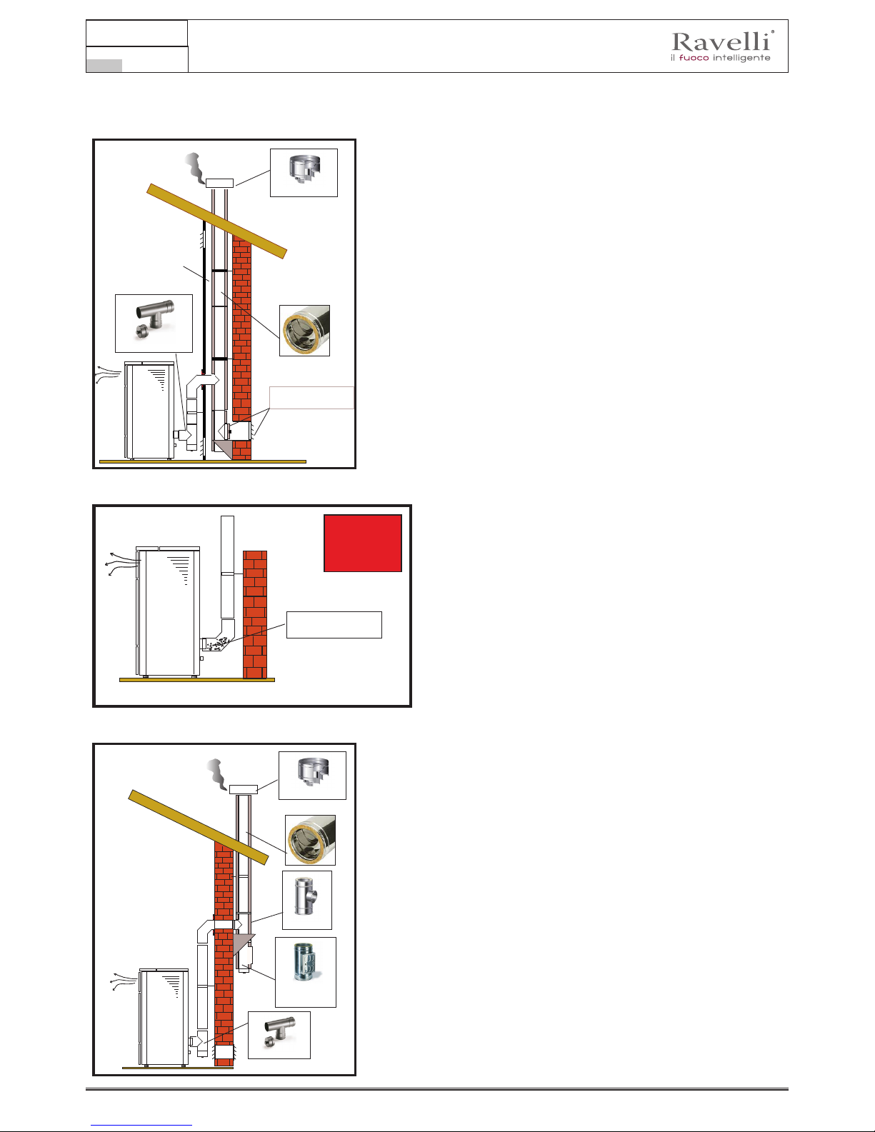
Use and maintenance manual Vela 7-9
Rev.1 20.02.18
EN
Pag.56
This type of installation (See Fig.1) requires an insulated
chimney pot, even if the entire conduit is installed inside
the building. Besides, the structure must be inserted into a
properly ventilated skylight shaft.
In the lower part of the chimney pot there is an inspection
cover, properly isolated from wind and rain.
It is possible to use an existing chimney or a shaft via ducting.
For this type of installation the standards on ducted smoke
evacuation systems must be complied with. In the lower part
of the chimney pot, inside the home, there is a "T" type tting
installed; externally there is another one installed, so that the
outside section can be inspected.
It is prohibited to install two 90° bend, since the ashes would
quickly obstruct smoke passage, causing draught problems in
the stove. (See Fig. 2)
Ashes deposited in the
90° bend
NO
Installation example for a stove/pellet stove
Smoke duct:
use of a non-insulated
tube
T Fitting
Insulated chimney
Fig.3
Protection from rain
T tting for condensation
Combustion ashes
collection chamber
+ condensation cap
Protection from rain
Fig.1
Grille for air passage into the
skylight shaft with opening for
inspecting the chimney
Skylight shaft
T tting for condensation
Insulated chimney
It is prohibited to install a 90° bend for the initial segment,
since the ashes would quickly obstruct smoke passage,
causing draught problems in the stove. (See Fig. 2)

Use and maintenance manual Vela 7-9
Page 57
Rev.1 20.02.18
EN
This type of installation (See Fig.4) requires an insulated
chimney pot, even if the entire smoke conduit is installed
outside the building.
In the lower part of the chimney there is a "T" type tting
installed with inspection cap.
It is prohibited to install a 90° bend for the initial segment,
since the ashes would quickly obstruct smoke passage,
causing draught problems in the stove. (See Fig.2)
This type of installation (See Fig.5) requires an
insulated chimney pot, since the entire smoke
conduit is installed inside the building, and the part is
located inside a pre-existing chimney pot.
In the lower part of the stove there is a "T" type tting
installed with inspection cap just like for the chimney
pot.
It is prohibited to install a 90° bend for the initial
segment, since the ashes would quickly obstruct
smoke passage, causing draught problems in the
stove. (See Fig.2)
INTERNAL CHIMNEY
Fig.5
Protection from rain
Covering sheet
Air-tight steel sheet metal
T tting with collection
chamber for condensation
Inspection hatch
Fig.4
Protection from rain
Insulated chimney
T tting with condensation drain and
collection chamber
This type of installation (See Fig.6) requires a
horizontal section to connect to a pre-existing
chimney pot.
Respect the slope indicated in gure, in order to
reduce the ashes depositing in the horizontal tube. In
the lower part of the chimney pot, there is a "T" type
tting installed with inspection cap, in the same was
as the chimney pot opening.
It is prohibited to install a 90° bend for the initial
segment, since the ashes would quickly obstruct
smoke passage, causing draught problems in the
stove. (See Fig.2)
2 - 3 mt
max
Height exceeding 4 mt
Slope 3 - 5 %
Max 2 -3 mt
INTERNAL CHIMNEY
Fig.6
T tting for condensation
Inspection hatch
Protection from rain

Use and maintenance manual Vela 7-9
Rev.1 20.02.18
EN
Pag.58
Connections
! IMPORTANT
The connections must be set up by a technician that is qualied and/or authorised by the
Manufacturer.
Connection with external air intake
The stove has been designed for hermetic installations.
To make the connection with an external air intake, proceed as follows:
step action
1
Connect a 50 mm diameter pipe to the combustion air inlet pipe at the back of the stove. Note: the pipe must be no
more than 2 m in length.
The air vent must be installed in such a way that it can not be blocked.
Chimney connection
The chimney must be sized so as to guarantee the draught declared by the Manufacturer.
Electrical connection
The plug of the stove power cable must be connected only after installation and assembly has been completed
of the device, and must remain accessible after installation.
To perform the electrical connection, proceed as follows:
step action
1 Connect the power cord to the back of the stove.
2 Connect the plug of the power cord to the wall socket.
Electric scheme
Schema elettrico KTR AIR (congurazione ventilata o canalizzata singola)
Vers. 03 del 22/03/16
!
"!!
!#
!"
!
$%
!
"
&!
$%
!'
!
&
&!
!'
$
%"!
%"!
M2
M3
S1
R1
S2
G1
nero
rosso
bianco
Schema elettrico Scheda madre
RETE ALIMENTAZIONE 220 V
S3
G4
G5
G2
Scheda OPZIONALE
per gestione
domotica
N
COM
NC
NO
G6
G2
NCG6NOG6C
G6
G5 G5
10 9 8 7 6 5 4 3 2 1
Connessione OPZIONALE per
gestione domotica
Neutro
M4
M5
Fase
M1
bianco
verde
T1
T5
T3
T2
T4
LEGEND:
Safety devices
T1 - Pellet safety
T2 - Vacuum switch
Motors
M1 - Infeed screw gear motor
M2 - Room fan
M3 - Fume exhaust system
M4 - Heat exchanger 1 fan
M5 - Heat exchanger 2 fan
Resistance
R1 - 250watt heaterSonde
Probes
S1 - Fume probe
S2 - External thermostat
S3 - Room probe
S4 - Rear or RRight Probe/
EXT. T.
S5 - RLeft Probe/EXT T.
General
G1 - Flow meter
G2 - Extractor revolution
reading encoder

Use and maintenance manual Vela 7-9
Page 59
Rev.1 20.02.18
EN
Testing and commissioning
Stove start-up must be preceded by testing, which includes an operational check of the following elements:
• connection to the smoke evacuation system;
• checking that all materials used to build the smoke duct, chimney and chimney pot are regulation and suitable for use.
The testing is positive only when all operational phases have been completed without any anomaly being detected.
Controls and use
Description of the handheld set:
The handheld set is shown in the picture below:
The information below will allow you to become familiar with the product and achieve the best performance.
How to insert the batteries in the handheld set:
Remove the protective cover of the battery on the back of the remote control as shown in Figure A, and insert the 3 batteries (mini
pen style battery AAA 1.5V) in the housing of the handheld set and observe the poles. Install the battery protective cover as shown
in gure B
The handheld set, after a short screen showing the Ravelli logo, will list the languages available in the menu.
Select the desired language using the scroll keys and conrm your selection with the conrmation button.
Wiring
Connect the power cord to the back of the stove and then to a wall socket. The I/O switch in the gure
should be set to I to power the stove. If voltage is not supplied check the state of the fuse installed in
the box below the switch (4A fuse). During the periods of inactivity, we recommend you disconnect the
power cord of the stove.
Preliminary Operations
NEVER INSERT INTO THE TANK OTHER KIND OF FUEL OTHER FROM THE PELLETS
COMPLYING WITH THE SPECIFICATIONS BELOW
The handheld set is shown in the picture below:
Description of the handheld set:
1
Increase button “UP” (selection key)
2
Decrease key “DOWN” (selection key)
3
ON/OFF or reset from “Sleep” mode key.
4
Display
5
Key for accessing the MENU and back
6
Conrmation key
1
2
5
6
4
3
In “Sleep” mode, the handheld set
screen is obscured, keeping however
active the radio communication with
the stove to reduce battery consumption.
What to check befor turning on the stove
Make sure you have removed all parts that pose the risk of burns from the combustion chamber or glass (various instructions or
stickers).
Before turning on the stove, make sure you have tted the grate on the support base and check that the door and the ash drawer
are properly close.
How to load the pellets
Fuel supply consists in the insertion of pellets from the top of the stove, by opening the door. During pellet loading prevent the pel-
let bag from coming into contact with hot surfaces.
Connect the power cord to the back of the stove and then to a wall socket. The I/O switch in the gure
should be set to I to power the stove. If voltage is not supplied check the state of the fuse installed in
the box below the switch (4A fuse). During the periods of inactivity, we recommend you disconnect the
power cord of the stove.
NEVER INSERT INTO THE TANK OTHER KIND OF FUEL OTHER FROM THE PELLETS
COMPLYING WITH THE SPECIFICATIONS BELOW
1
Increase button “UP” (selection key)
2
Decrease key “DOWN” (selection key)
3
ON/OFF or reset from “Sleep” mode key.
4
Display
5
Key for accessing the MENU and back
6
Conrmation key
1
2
5
6
4
3
Figure A
Figure B
In “Sleep” mode, the handheld set
screen is obscured, keeping however
active the radio communication with
the stove to reduce battery con-
sumption.
1
Increase button “UP” (selection key)
2
Decrease key “DOWN” (selection key)
3
ON/OFF or reset from “Sleep” mode key.
4
Display
5
Key for accessing the MENU and back
6
Conrmation key
5
6
4
Figure B
In “Sleep” mode, the handheld set
screen is obscured, keeping however
active the radio communication with
the stove to reduce battery con-
sumption.
ITALIANO
DEUTSCH
ENGLISH
FRANCAIS
DANSK
NEDERLANDS
ESPANIOL

Use and maintenance manual Vela 7-9
Rev.1 20.02.18
EN
Pag.60
Handheld touch radio initialization
In order to operate correctly, the handheld set should be interfaced with the electronic board installed inside the stove. For this
reason, on display appears the following message:
If the handheld set is used for the rst time, select YES using the selection keys and conrm with the dedicated key. On the display
of the handheld set appears the following:
Hold down for a few seconds the button of radio communication (RADIO ADJ) of the PCB, located on the back of the stove, to
initialize the device.
The ashing yellow LED indicates that the circuit board is waiting to receive the signal from the handheld set.
By pressing the enter key on the handheld set, the components start communicating with each other. A check sign on the display,
accompanied by a sound signal, shows that the initialization of the handheld set has been completed sucessfully
Description of the display
The display of the handheld set is described below (in stand-by mode):
Pag.20 Pag.21
Vers. 01 of:07.04.14 Vers. 01 of:07.04.14
1
FIRST INSTALLATION?
YES
The display is subdivided into three parts:
1. It shows the current room temperature measured by the handheld set. Moreover, if you press the DOWN scroll key you will
display the temperature settings that can be changed using the two UP/DOWN keys. Any change made is conrmed automatically
within 3 seconds from the change or by pressing the conrmation key. A sound signal indicates that the change has been con-
rmed.
Pag.20 Pag.21
Vers. 01 of:07.04.14 Vers. 01 of:07.04.14
2
1
FIRST INSTALLATION?
PRESS THE KEY RADIO
ADJ ON THE STOVE
YES
The display is subdivided into three parts:
1. It shows the current room temperature measured by the handheld set. Moreover, if you press the DOWN scroll key you will
display the temperature settings that can be changed using the two UP/DOWN keys. Any change made is conrmed automatically
within 3 seconds from the change or by pressing the conrmation key. A sound signal indicates that the change has been con-
rmed.
In the inactive phases (combined with the 3rd part of the display) indicates the state of the stove.
In the active phases, it indicates the operating power of the stove.
In addition, by pressing the DOWN scroll button, you can display the power settings, that can be edited using the two scroll
keys
UP/DOWN: The conrmation of any change takes place automatically within 3 seconds from the change or by pressing the con-
rmation key. A sound signal indicates that the change has been conrmed.
4
32
1 5
1
2
3
4
5
Serial port
Handheld cable connection socket
ADJ radio: button to connect your handheld to the board
Signalling LED
Red: active alarm
Yellow: Waiting communication with the handheld set
Green: Cooker switched on
Cooker ON/OFF key
User’s manual HANDHELD TOUCH RADIO User’s manual HANDHELD TOUCH RADIO
Pag.20 Pag.21
Vers. 01 of:07.04.14 Vers. 01 of:07.04.14
2
3
1
FIRST INSTALLATION?
PRESS THE KEY RADIO
ADJ ON THE STOVE
YES
Handheld touch radio initialization
In order to operate correctly, the handheld set should be interfaced with the electronic board installed inside the stove. For this
reason, on display appears the following message:
If the handheld set is used for the rst time, select YES using the selection keys and conrm with the dedicated key.
On the display of the handheld set appears the following:
Hold down for a few seconds the button of radio communication (RADIO ADJ) of the PCB, located on the back of the stove, to
initialize the device.
The ashing yellow LED indicates that the circuit board is waiting to receive the signal from the handheld set.
By pressing the enter key on the handheld set, the components start communicating with each other. A check sign on the display,
accompanied by a sound signal, shows that the initialization of the handheld set has been completed sucessfully .
When you replace the batteries, you do not have to run the initialization procedure of the handheld set. In this case, when
on display appears the message “FIRST INSTALLATION ?”, select NO and press the conrmation key.
The display is subdivided into three parts:
1. It shows the current room temperature measured by the handheld set. Moreover, if you press the DOWN scroll key you will
display the temperature settings that can be changed using the two UP/DOWN keys. Any change made is conrmed automatically
within 3 seconds from the change or by pressing the conrmation key. A sound signal indicates that the change has been con-
rmed.
In the inactive phases (combined with the 3rd part of the display) indicates the state of the stove.
In the active phases, it indicates the operating power of the stove.
In addition, by pressing the DOWN scroll button, you can display the power settings, that can be edited using the two scroll
keys
UP/DOWN: The conrmation of any change takes place automatically within 3 seconds from the change or by pressing the con-
rmation key. A sound signal indicates that the change has been conrmed.
Time and date setting
Below are given the steps for accessing the relative menu.
Press the key “access menu” to
access
the
MENU page
User’s manual HANDHELD TOUCH RADIO User’s manual HANDHELD TOUCH RADIO
Pag.20 Pag.21
Vers. 01 of:07.04.14 Vers. 01 of:07.04.14
2
3
1
2
3
1
FIRST INSTALLATION?
PRESS THE KEY RADIO
ADJ ON THE STOVE
YES
Handheld touch radio initialization
In order to operate correctly, the handheld set should be interfaced with the electronic board installed inside the stove. For this
reason, on display appears the following message:
If the handheld set is used for the rst time, select YES using the selection keys and conrm with the dedicated key.
On the display of the handheld set appears the following:
Hold down for a few seconds the button of radio communication (RADIO ADJ) of the PCB, located on the back of the stove, to
initialize the device.
The ashing yellow LED indicates that the circuit board is waiting to receive the signal from the handheld set.
By pressing the enter key on the handheld set, the components start communicating with each other. A check sign on the display,
accompanied by a sound signal, shows that the initialization of the handheld set has been completed sucessfully .
When you replace the batteries, you do not have to run the initialization procedure of the handheld set. In this case, when
on display appears the message “FIRST INSTALLATION ?”, select NO and press the conrmation key.
Description of the display
The display of the handheld set is described below (in stand-by mode):
After 5 minutes of inactivity, the display of the handheld set turns dark, switching to “SLEEP” mode, while maintaining the
radio connection with the stove. By pressing the key ON/OFF, the display becomes active again.
The rst pressure of any key with the display active, lights up its backlight, but it is not, however ,
considered a command.
The display is subdivided into three parts:
1. It shows the current room temperature measured by the handheld set. Moreover, if you press the DOWN scroll key you will
display the temperature settings that can be changed using the two UP/DOWN keys. Any change made is conrmed automatically
within 3 seconds from the change or by pressing the conrmation key. A sound signal indicates that the change has been con-
rmed.
In the inactive phases (combined with the 3rd part of the display) indicates the state of the stove.
In the active phases, it indicates the operating power of the stove.
In addition, by pressing the DOWN scroll button, you can display the power settings, that can be edited using the two scroll
keys
UP/DOWN: The conrmation of any change takes place automatically within 3 seconds from the change or by pressing the con-
rmation key. A sound signal indicates that the change has been conrmed.
Time and date setting
Below are given the steps for accessing the relative menu.
Press the key “access menu” to
access
MENU page
Press the key
“conrm” to
access the
SETTINGS
page

Use and maintenance manual Vela 7-9
Page 61
Rev.1 20.02.18
EN
The display is subdivided into three parts:
It shows the current room temperature measured by the handheld set. Moreover, if you press the DOWN scroll key you will
display the temperature settings that can be changed using the two UP/DOWN keys. Any change made is conrmed automatically
within 3 seconds from the change or by pressing the conrmation key. A sound signal indicates that the change has been conrmed.
Icon indicating the status of the stove (see synthetic phase diagrams).
In the inactive phases (combined with the second part of the display) indicates the state of the stove.
In the active phases, it indicates the operating power of the stove.
In addition, by pressing the DOWN scroll button, you can display the power settings, that can be edited using the two scroll keys UP/
DOWN: The conrmation of any change takes place automatically within 3 seconds from the change or by pressing the conrmation
key. A sound signal indicates that the change has been conrmed.
Time and date setting
Below are given the steps for accessing the relative menu.
1
The display is subdivided into three parts:
1. It shows the current room temperature measured by the handheld set. Moreover, if you press the DOWN scroll key you will
display the temperature settings that can be changed using the two UP/DOWN keys. Any change made is conrmed automatically
within 3 seconds from the change or by pressing the conrmation key. A sound signal indicates that the change has been con-
rmed.
1
2
3
2
1
The display is subdivided into three parts:
1. It shows the current room temperature measured by the handheld set. Moreover, if you press the DOWN scroll key you will
display the temperature settings that can be changed using the two UP/DOWN keys. Any change made is conrmed automatically
within 3 seconds from the change or by pressing the conrmation key. A sound signal indicates that the change has been con-
rmed.
In the inactive phases (combined with the 3rd part of the display) indicates the state of the stove.
In the active phases, it indicates the operating power of the stove.
In addition, by pressing the DOWN scroll button, you can display the power settings, that can be edited using the two scroll
keys
UP/DOWN: The conrmation of any change takes place automatically within 3 seconds from the change or by pressing the con-
rmation key. A sound signal indicates that the change has been conrmed.
MENU USER
USER
SETTINGS
SETTINGS
DATE-TIME
USER
COMFORT CLIMA
MANUFACTURER
ENGINEER
ENABLE EXT. TH.
CONTRAST
FW VERSION
ADJUST
LANGUAGE
SCREW FEEDING
CHRONOTHERMOSTAT
AIR-PELLET SET
STOVE STATE
In the inactive phases (combined with the 3rd part of the display) indicates the state of the stove.
In the active phases, it indicates the operating power of the stove.
In addition, by pressing the DOWN scroll button, you can display the power settings, that can be edited using the two scroll
keys
UP/DOWN: The conrmation of any change takes place automatically within 3 seconds from the change or by pressing the con-
rmation key. A sound signal indicates that the change has been conrmed.
Press the key “access menu” to
access
the
MENU page
Press the key
“conrm” to
access the
SETTINGS
page
Press the key
“conrm”
to access the
USER page
Press the key “con-
rm”
to access the page
DATE-TIME
Press the key “selection” for
“selection”
to switch to the second page
of USER MENU and select
SETTINGS.
Press the increase key to change every single value
Press the increase key to change every single value
Press “conrm” to conrm the settings and switch to the next
value.
By pressing the key “back” for several times you will display
the stand-by page.

Use and maintenance manual Vela 7-9
Rev.1 20.02.18
EN
Pag.62
PROCEDURES FOR USE
If the chimney catches re you must call the re brigade immediately.
Checks prior to start-up
You have read and perfectly understood the contents of this instructions manual.
Before lighting the stove, you must ensure that:
• the combustion chamber is clean;
• every element that could burn has been removed (instructions, various stickers).
! IMPORTANT
During the rst hours of use the paints used for the stove nish may release an unpleasant
odour. You might also smell the typical odour of metal parts subject to high temperatures.
Make sure sufcient air circulation is guaranteed in the room. These unavoidable
inconveniences will disappear after the rst hours of operation. To reduce your discomfort
to a minimum, keep the stove on for a few hours on low power and in the beginning, do not
overload it, avoiding intense heating-cooling cycles.
! IMPORTANT
At the initial start-up, the paint nishes drying and hardens. Accordingly, to avoid ruining
it, we advise you not to touch the stove’s painted surfaces at this time.
Recharge the fuel
Use only wood pellets, the characteristics shown in this manual.
Pellet loading must take place when the stove is off. If it is performed with the stove on, the operation must be
completed within 1 minute otherwise the stove will switch off.
During pellet loading prevent the pellet bag from coming into contact with hot surfaces.
Switching the appliance on and off
From the “stand-by” screen, it is possible to switch the stove on and off by keeping the ON / OFF button pressed on the device for a
few seconds. An acoustic signal will warn you that the appliance has switched on or off. In case it is not possible using your handheld
you can switch the appliance on / off using the appropriate button on the electronic board.
! IMPORTANT
The brazier is mechanically cleaned before each ignition, except after the initial screw
feed and in case of re-ignition after an FAILED IGNITION alarm
Do not switch off the heater by unplugging the plug from the wall socket.
Failed ignition
To turn the stove back on, reset the alarm by keeping the power button on the handheld (or on the electronic card) pressed until the
acoustic signal is heard and then switch on again.
It is not necessary to remove any unburnt pellets inside the brazier. In fact, as soon as the user reboots the stove, the system tries
to ignite any fuel left in the brazier before starting the loading phase.
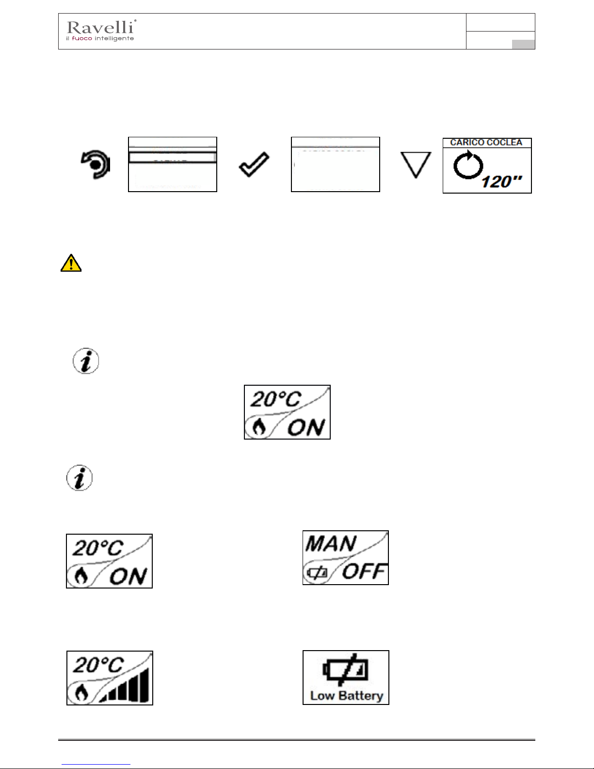
Use and maintenance manual Vela 7-9
Page 63
Rev.1 20.02.18
EN
Feed screw loading
Before starting the stove for the rst time, whenever the stove is in alarm “06 - Pellets nished”, and in any case whenever the hopper
has emptied completely, the initial feed screw loading is required. This phase involves lling the pellet loading system so that when
the system is started, it is ready to load the pellets into the brazier.
In the event that the feed screw operations are not carried out, there may be stove ignition failures.
THE PRE-SET INITIAL LOADING TIME IS SUCH TO ALSO INCLUDE ENOUGH PELLETS FOR THE FIRST IGNITION.
AFTER THE INITIAL LOADING OPERATIONS, NO BRAZIER CLEANING WILL PRECEDE THE IGNITION PHASE.
Setting operating temperature and power:
Set the two values following the indications given in the chapter “Description of thr display”
Turning the device on
Keep the key ON/OFF pressed for a few seconds to turn on the stove.
User’s manual HANDHELD TOUCH RADIO User’s manual HANDHELD TOUCH RADIO
Pag.22 Pag.23
Vers. 01 of:07.04.14 Vers. 01 of:07.04.14
Loading the auger
MENU
USER
SCREW FEEDING
SCREW FEEDING
CHRONOTHERMOSTAT
AIR-PELLET SET
STOVE STATE
USER
MANUFACTURER
ENGINEER
ALWAYS EMPTY THE BRAZIER BEFORE TURNING THE STOVE ON AND ALWAYS CHECK
THAT ALL NONE OF ITS HOLES IS CLOGGED NEVER EMPTY THE RBAZIER INSIDE THE HOPPER.
FIRE HAZARD.
Carry out this operation to facilitate stove’s rst start operations; You should also check that you have introduced pellets
into the hopper and wait until the stove is in “SHUTDOWN” or “FINAL CLEANING” mode. The number expressed in sec-
onds indicates the rotation time of the infeed screw during the rst loading cycle. Once this time has elapsed, the infeed
screw stops immediately and then pellets are emptied from the grate before turning on the equipment.
Below are given the steps for accessing the relative menu.
Press the key “access
menu” to access
the
MENU page
Press the key
“conrm”
to access the
USER page
At the end of the auger loading, the display shows 0 “and automatically switches to the USER menu page.
Press the key for several times until the Stand-by page is displayed.
Setting operating temperature and power:
Set the two values following the indications given in the chapter “Description of thr display”
Turning the device on
Keep the key ON/OFF pressed for a few seconds to turn on the stove.
Press CONFIRM to enable
the rotation of the auger
The appearance of the message “ADJUST THE RDS SYSTEM” indicates that the initial parameter testing procedure
and calibration has been unsuccessfully. This indication does not cause stove blockage (see the SIGNALLING POP UP
section).
On the display of the handheld set appears the following:
Press and hold the ON/OFF button to turn off the stove door, and reset any alarms triggered.
In case the infeed screw operations described avobe have not been executed, the stove may fail to turn on. In this case,
carry out the operations described above and empty the brazier and reset the alarm.
If the stove still fails to turn on, check that the grate is properly installed and perfectly adherent to the base, and also check that
there are no deposits that prevent the smooth passage of air to enable ignition. If the problem persists, contact the support ser-
vice.
Sequence of ignition phases
SWITCH-ON- initial pellet loading phase;
WAIT FLAME - ame
development wait
phase;
FLAME PRESENT - ame stabilization
phase and reduction of combustible
inside the brazier;
What happens if the batteries are empty?
If the battery is discharged, within the
“drop” is shown a symbol that indicates
that the battery is empty, while maintain-
ing active the features of your device.
WORK - operation phase
described in
the dedicated chapter;
As soon as the level of the battery
prevents the radio communication the
handheld set displays on full screen the
picture of empty battery and all device
functions are locked until the batteries
are replaced
CONNECT AN EXTERNAL THERMOSTAT WITH A SIMPLE DRY CONTACT, THEREFORE, NOT POWERED. MORE-
OVER, WE RECOMMEND YOU USE A THERMOSTAT WITH A MINIMUM OFFSET OF 3°C IF YOU INTEND TO USE
THE COMFORT CLIMA FUNCTION.
Operating phases of the appliance
Modulation
During the work phase, the appliance should reach the room temperature set; when this condition is met, the stove switches to
MODULATION mode in which fuel consumption and ventilation are minimum.
If you wish to detect the ambient temperature by means of an external thermostat (optional), this must be connected to
the appropriate connector on the rear side of the stove; and you will have to activate the reading in “SETTINGS - EN -
ABLE THERMOSTAT.” On display appears the writing TON / TOFF based on thermostat request.
Comfort climate
The activation of this function enables the stove to reduce pellet consumption by activating the modulation phases, after the desired
temperature has been reached. Subsequently, the stove checks that the temperature is maintained steady for a preset time. If this
condition is met, it automatically switches off, and on display appears the writing ECO.
The stove turns on again when the temperature drops below the set threshold.
Below are given the steps for accessing the relative menu.
Press the key
“access menu” to
access
the
MENU page
Once you have accessed the Climate Comfort menu, it is possible to operate on the 3 types of settings dedicated to the function:
Press the key for several times until the Stand-by page is displayed.
MENU
USER
MANUFACTURER
ENGINEER
USER
USER
COMFORT CLIMA
SETTINGS
SCREW FEEDING
CHRONOTHERMOSTAT
AIR-PELLET SET
STOVE STATE
CONNECT AN EXTERNAL THERMOSTAT WITH A SIMPLE DRY CONTACT, THEREFORE, NOT POWERED. MORE-
OVER, WE RECOMMEND YOU USE A THERMOSTAT WITH A MINIMUM OFFSET OF 3°C IF YOU INTEND TO USE
THE COMFORT CLIMA FUNCTION.
If you wish to detect the ambient temperature by means of an external thermostat (optional), this must be connected to
the appropriate connector on the rear side of the stove; and you will have to activate the reading in “SETTINGS - EN -
ABLE THERMOSTAT.” On display appears the writing TON / TOFF based on thermostat request.
Press the “menu access”
button to access the
MENU screen.
Press the “confirm”
button to access the
USER screen
Press the “confirm”
button to activate feed
screw rotation

Use and maintenance manual Vela 7-9
Rev.1 20.02.18
EN
Pag.64
MENU
USER
MANUFACTURER
ENGINEER
USER
USER
COMFORT CLIMA
COMFORT CLIMA
COMFORT CLIMA
COMFORT CLIMA
ENABLE COMFORT
ENABLE COMFORT
ENABLE COMFORT
RESTART DELTA
RESTART DELTA
SHUTDOWN DELAY
SHUTDOWN DELAY
SHUTDOWN DELAY
SHUTDOWN DELAY
ENABLE COMFORT
ENABLE COMFORT
COMFORT CLIMA DELTA
COMFORT CLIMA DELTA
RESTART DELTA
SHUTDOWN DELAY
SETTINGS
SCREW FEEDING
CHRONOTHERMOSTAT
AIR-PELLET SET
STOVE STATE
CONNECT AN EXTERNAL THERMOSTAT WITH A SIMPLE DRY CONTACT, THEREFORE, NOT POWERED. MORE-
OVER, WE RECOMMEND YOU USE A THERMOSTAT WITH A MINIMUM OFFSET OF 3°C IF YOU INTEND TO USE
THE COMFORT CLIMA FUNCTION.
Operating phases of the appliance
Modulation
During the work phase, the appliance should reach the room temperature set; when this condition is met, the stove switches to
MODULATION mode in which fuel consumption and ventilation are minimum.
If you wish to detect the ambient temperature by means of an external thermostat (optional), this must be connected to
the appropriate connector on the rear side of the stove; and you will have to activate the reading in “SETTINGS - EN ABLE THERMOSTAT.” On display appears the writing TON / TOFF based on thermostat request.
Comfort climate
The activation of this function enables the stove to reduce pellet consumption by activating the modulation phases, after the desired
temperature has been reached. Subsequently, the stove checks that the temperature is maintained steady for a preset time. If this
condition is met, it automatically switches off, and on display appears the writing ECO.
The stove turns on again when the temperature drops below the set threshold.
Below are given the steps for accessing the relative menu.
Press the key
“access menu” to
access
the
MENU page
Press the key
“conrm”
to access the
USER page
Once you have accessed the Climate Comfort menu, it is possible to operate on the 3 types of settings dedicated to the function:
Press the key for several times until the Stand-by page is displayed.
Press the key “selection” for
“selection”
to switch to the second page
of USER MENU and select
CLIMATE COMFORT.
Operating phases of the appliance
Modulation
Comfort climate

Use and maintenance manual Vela 7-9
Page 65
Rev.1 20.02.18
EN
User’s manual HANDHELD TOUCH RADIO User’s manual HANDHELD TOUCH RADIO
Pag.24 Pag.25
Vers. 01 of:07.04.14 Vers. 01 of:07.04.14
5
1
4
MENU
USER
MANUFACTURER
ENGINEER
USING THIS METHOD, IT IS NECESSARY TO VERIFY THAT AFTER EACH AUTOMATIC SHUTDOWN
THE GRATE IS ALWAYS VERY CLEAN TO GUARANTEE CORRECT AUTOMATIC SWITCH ON.
AUTOMATIC SWITCH ON.
The rst setting allows the activation of the CLIMATE COMFORT function. This function is intended to ensure that the room tem
-perature set is maintained steady upon setting the maximum period of “X” minutes (SWITCH-OFF DELA
Y: 5 MIN) before switch-ing to ECO STOP phase. The STOVE maintains this state until the temperature drops below the set
value (CLIMATE COMFORT DELTA : 5℃).
For example, with the room temperature at 21 ° C, the stove switches of f when this temperature is
reached and restarts when the temperature reaches 15°C (21°C - 5°C - 0,5°C tolerance).
You can also activate the function using an external thermostat, keeping in mind that this does not include the value of the hyster
-esis.
We recommend you use an external thermostat with a histeresys value that can be set to maximum 3°C.
The operation of the stove could activate the switch ON/OFF phases for several times during the day;
this may affect the service life of the ignition coil.
Description of menu functions
Press the key to access the MENU page
The TECHNICIAN and MANUFACTURER menus are protected by password.
Chronothermostat
With the Chrono-thermostat function you can program the automatic switch ON/OFF of the stove for each day of the week
for each day of the week in 4 independent time intervals (SET CHRONO 1-2-3-4)
Below are given the steps for accessing the relative menu starting from Stand-By mode.
By pressing the Increment key you can change each value and, at step 3, enable the days of the week;
By pressing the Increment key you can change each value and, at step 3, enable the days of the week;
Press “conrm” to conrm the settings and switch to the next value;
Press the “back” button to return to the CHRONO-THERMOSTAT page.
As per the above example, it has been set as CHRONO 1 an ignition from 08.30 to 21.30 from MONDAY to FRIDAY at the oper-
ating power 5 with a room temperature set at 21 ° C. Programmes 2-3-4 can be set in the same manner.
To exit the CHRONO-THERMOSTAT function and return to Stand-by page, press the button repeatedly.
AIR / PELLETS setting
Setting of the PELLET-FLOW mix enables you to immediately change the quantity of pellet loaded in the brazier and the air inow.
The stove is tested and inspected with DIN PLUS certied pellets. If using another type of pellets or uncertied pellets, fuel may
need adjustment. Usually, the variation involves the FLOW percentage to adjust the input air and, therefore, the combustion; should
the regulation of ow be insufcient, it may be necessary to also change the percentage of PELLET load.
Below are given the steps for accessing the relative menu starting from Stand-By mode.
The rst setting allows the activation of the CLIMATE COMFORT function. This function is intended to ensure that the room tem
perature set is maintained steady upon setting the maximum period of “X” minutes (SWITCH-OFF DELA Y: 5 MIN) before switch-ing
to ECO STOP phase. The STOVE maintains this state until the temperature drops below the set value (CLIMATE COMFORT DELTA:
5°C). For example, with the room temperature at 21 ° C, the stove switches of f when this temperature is reached and restarts when
the temperature reaches 16°C (21°C - 5°C). You can also activate the function using an external thermostat, keeping in mind that this
does not include the value of the hysteresis.
Description of menu functions
Press the increase/decrease keys
“increase/decrease”
to change the ventilation.
To exit the page and return to Stand-by page, press the button repeatedly.
The exit key shows the CHRONO menu to set other variables related to the menu functions.
Press the key
“enter” at the end of the
setting, from the following
CHRONO page
CHRONO
CHRONO
ENABLE CHRONO
ENABLE CHRONO
ENABLE CHRONO
ENABLE CHRONO
VENTILATION POW.
SET CHRONO 1
SET CHRONO 1
SET CHRONO 2
SET CHRONO 2
SET CHRONO 3
SET CHRONO 3
SET CHRONO 4
SET CHRONO 4
Manuale utente PALMARE IDRO TOUCH RADIO Manuale utente PALMARE IDRO TOUCH RADIO
Pag.32 Pag.33
Vers. 01 del 07/04/15 Vers. 01 del 07/04/15
Press the key
“conrm” to
access the
SETUP
SETTINGS
Press the key
“selection” to switch
to the function
VERSION FW.
Press the key
“conrm”
to access the function
Use the UP/DOWN keys to change the value read by the
room temperature probe installed inside the handheld
set, with respect to a reference value.
The value can vary from -10°C to 10°C.
The standard value is 0°C.
By pressing the following key you will conrm of data
and switch to the page within SETTINGS menu
To exit the page and return to Stand-by page, press the button repeatedly.
The exit key shows the CHRONO menu to set other variables related to the menu functions.
The temperature read by the handheld unit controls the modulation of the stove. If you want to adjust the ventilation by
adjusting the stove, set the fan to A mode as shown in the relative chapter.
Press the key
“access menu” to
access the
MENU page
Press the key
“conrm”
to access the
USER page
Press the key
“conrm”
to quickly switch to
VENTILATION.
Press the increase/decrease keys
“increase/decrease”
to change the ventilation.
Pages displayed upon the activation of advanced layouts
By activating a layout different from the standard (layout 0), even if maintaining the same functions of the menu, the “Stand-by” page will
display all connected utilities such as the temperature of the boiler of the puffer.
Below is shown the new display mode and the function of every icon for every layout, to change the various settings.
Layout 1 (DHW Boiler + heating control)
The following layout can be used when you have a boiler that is not equipped with plate heat exchanger and you intend to buy a puffer
that should be connected to the circuit to produce hot domestic water.
In this type of circuit, room temperature is controlled however by the handheld unit which, being a radio device, acts as a remote
chronothermostat. The boiler is managed by the thermostove through a contact or immersion probe (not supplied) connected directly
to the back of the stove. Below is shown the new “Stand-by” mode.
By setting the SUMMER function, the 3-way valve remains xed in a single position, enabling the release of heat output
by the stove exclusively inside the boiler. As soon as this condition is reached, the boiler switches to ECO STOP mode.
The operation is the same as for the basic layout except for the fact that in this layout, the boiler exchanges heat directly in the
boiler (priority); when the temperature set is reached, the 3-way valve changes its position and the boiler starts exchanging heat within
the heating circuit. From this moment, the stove is controlled by the radio handheld unit for contolling the room
temperature or via H2 setting (see the operation with layout 0 to nd the data on modulation, eco stop etc.).
The 3-way valve is directed again into the boiler when:
- there is a request from the Boiler;
- there is a requested from the ow switch (optional, if connected).
The stove restarts from Eco-stop or Stand by mode according to heating requests or boiler requests.
Press the key
“access menu” to
access the
MENU page
Press the key
“conrm”
to access the
USER page
Press the key
several times
to quickly switch to
CRONO-THERMOSTAT.
If the type of system designed requires controlling the 3-way valve (diagram 1 and 3), it is necessary to purchase the
optional kit from the retailer or the authorized Ravelli dealer.
DATE-TIME
DATE-TIME
ENABLE EXT. T
ENABLE EXT. T
SEASON
SEASON
CONTRAST
CONTRAST
FW VERSION
FW VERSION
LANGUAGE
LANGUAGE
ADJUST
ADJUST
ADJUST
MENU
USER
TECHNICIAN
VENTILATION POW.
USER
POWER SETTING
CHRONOTHERMOSTAT
SCREW LOADING
SET AIR-PELLET
MENU
USER
TECHNICIAN
USER USER
POWER SETTING POWER SETTING
SET AIR-PELLET
SET AIR-PELLET
CHRONOTHERMOSTAT
CHRONOTHERMOSTAT
SCREW LOADING
SCREW LOADING
ENABLE CHRONO
MANUFACTURER’S
MANUFACTURER’S
Chronothermostat

Use and maintenance manual Vela 7-9
Rev.1 20.02.18
EN
Pag.66
Manuale utente PALMARE IDRO TOUCH RADIO Manuale utente PALMARE IDRO TOUCH RADIO
Pag.30 Pag.31
Vers. 01 del 07/04/15 Vers. 01 del 07/04/15
Below are given the steps for accessing the relative menu starting from Stand-By mode.
Stove State
Press the key
“access menu” to
access the
MENU page
Press the key
“conrm”
to access the
USER page
Press the key
several times
to quickly switch to
Stove STATUS.
In this mode you can check the proper operation of the most important parameters of the appliance. Here is a list of real data of the
stove useful for service during inspection.
Settings > Enable thermostat
Press the “enter” key
to access the
SETTINGS
Press the key
“conrm”
to enable the function.
Settings > Season
Press the key
“conrm” to
access the
SETUP
SETTINGS
Use the UP/DOWN keys to change the WINTER/
SUMMER season. Function that can be set when
working with DHW puffer (Boiler).
MENU
STOVE STATE
STOVE STATE
STOVE STATE
STOVE STATE
USER
ACTIVE PARTS
ACTIVE PARTS
ACTIVE PARTS
ACTIVE PARTS
ACTUAL STATES
PUMP
PRESSURE 1.1 BAR
SHUTDOWN
POWER MOD
HH T …
EXT.T …
FLAME T 340°C
FUME T 120°C
F. EX. T 30°C
C. EX. T 55°C
EL B. T---25°C
T. CALDERA
T.PUFFER H
T.PUFFER L
3-WAY VALVE HEAT
ACTUAL STATES
ACTUAL STATES
ACTUAL STATES
H20 TEMPERATURE
H20 TEMPERATURE
v
H20 TEMPERATURE
TECHNICIAN
STATE TEMPERATURE
STATE TEMPERATURE
STATE TEMPERATURE
STATE TEMPERATURE
USER
USER
POWER SETTING
STOVE STATE
CHRONOTHERMOSTAT
COMFROT CLIMA
SCREW LOADING
SETTING
SET AIR-PELLET
MANUFACTURER’S
RPM
T
Tsk
g/min
°C
°C
Stove state
Settings > Enable thermostat
Press the “enter” key
to access the
SETTINGS
Press the key
“selection” to switch to
ENABLE THERMOSTAT.
Press the key
“conrm”
to access the function
Press the key
“conrm”
to enable the function.
In Stand-By mode, instead of room temperature measured
and settable, appears the line T ON if the room in which
the thermostat is installed has not reached the temperature
requested or the writing T OFF if the temperature in the
room is reached.
Press the key for several
times
to return to
“STAND BY” page
DATE-TIME
DATE-TIME
ENABLE THERMOSTAT
ENABLE THERMOSTAT
ENABLE EXT. T
ENABLE EXT. T
SEASON
SEASON
CONTRAST
CONTRAST
FW VERSION
FW VERSION
LANGUAGE
LANGUAGE
ADJUST
ADJUST
Settings > Enable thermostat
Stove state
Flame temperature
Temperature read by the handheld uit

Use and maintenance manual Vela 7-9
Page 67
Rev.1 20.02.18
EN
Settings > Enable thermostat
Press the “enter” key
to access the
SETTINGS
Press the key
“selection” to switch to
ENABLE THERMOSTAT.
Press the key
“conrm”
to access the function
Press the key
“conrm”
to enable the function.
In Stand-By mode, instead of room temperature measured
and settable, appears the line T ON if the room in which
the thermostat is installed has not reached the temperature
requested or the writing T OFF if the temperature in the
room is reached.
Press the key for several
times
to return to
“STAND BY” page
Settings > Contrast
Press the key
“conrm” to
access the
SETUP
SETTINGS
Press the key
“selection” to switch
to the function
CONTRAST.
Press the key
“conrm”
to access the function
Use the UP/DOWN keys to change contrast setting and obtain
a better visualisation of the information shown on the handheld
set.
The value can vary from 0 to 100. 50 with respect to the
standard value.
By pressing the following key you will conrm of data
and switch to the page within SETTINGS menu.
Settings > Season
Press the key
“conrm” to
access the
SETUP
SETTINGS
Press the key
“selection” to switch
to the function
CONTRAST.
Press the key
“conrm”
to access the function
Use the UP/DOWN keys to change the WINTER/
SUMMER season. Function that can be set when
working with DHW puffer (Boiler).
See chap. Evolved hydraulic diagrams
By pressing the following key you will conrm of data
and switch to the page within SETTINGS menu.
Press the “enter” key to
access the
SETTINGS
Press the key
“selection” to switch to
CONTRAST.
Press the key
“conrm”
to access the function
Settings > Firmware version
By pressing the button you will conrm the data and switch to the page within the SETTINGS menu.
DATE-TIME
DATE-TIME
DATE-TIME
DATE-TIME
DATE-TIME
WINTER
CONTRAST
FIRMWARE
SUMMER
DATE-TIME
ENABLE THERMOSTAT
ENABLE THERMOSTAT
ENABLE EXT. T
ENABLE EXT. T
ENABLE EXT. T
ENABLE EXT. T
ENABLE EXT. T
ENABLE EXT. T
SEASON
SEASON
SEASON
SEASON
SEASON
SEASON
CONTRAST
CONTRAST
CONTRAST
CONTRAST
CONTRAST
CONTRAST
FW VERSION
FW VERSION
FW VERSION
FW VERSION
FW VERSION
FW VERSION
LANGUAGE
LANGUAGE
LANGUAGE
LANGUAGE
LANGUAGE
LANGUAGE
ADJUST
ADJUST
ADJUST
ADJUST
ADJUST
ADJUST
DATE-TIME
ENABLE EXT. T
SEASON
CONTRAST
FW VERSION
LANGUAGE
ADJUST
DATE-TIME
ENABLE EXT. T
SEASON
CONTRAST
FW VERSION
LANGUAGE
ADJUST
Settings > Season
Settings > Contrast
Settings > Firmware version
Manuale utente PALMARE IDRO TOUCH RADIO Manuale utente PALMARE IDRO TOUCH RADIO
Pag.32 Pag.33
Vers. 01 del 07/04/15 Vers. 01 del 07/04/15
To access the next setting, follow the steps given above or simply remove and replace the batteries.
The device resets and prompts you again to select the language you want to set.
Settings > Language
Manuale utente PALMARE IDRO TOUCH RADIO Manuale utente PALMARE IDRO TOUCH RADIO
Pag.32 Pag.33
Vers. 01 del 07/04/15 Vers. 01 del 07/04/15
Press the key
“conrm” to
access the
SETUP
SETTINGS
Press the key
“selection” to switch
to the function
VERSION FW.
Press the key
“conrm”
to access the function
To access the next setting, follow the steps given above or simply remove and replace the batteries.
The device resets and prompts you again to select the language you want to set.
Settings > Language
Settings > Adjust
Use the UP/DOWN keys to change the value read by the
room temperature probe installed inside the handheld
set, with respect to a reference value.
The value can vary from -10°C to 10°C.
The standard value is 0°C.
By pressing the following key you will conrm of data
and switch to the page within SETTINGS menu
To exit the page and return to Stand-by page, press the button repeatedly.
The exit key shows the CHRONO menu to set other variables related to the menu functions.
DATE-TIME
DATE-TIME
ENABLE EXT. T
ENABLE EXT. T
SEASON
SEASON
CONTRAST
CONTRAST
FW VERSION
FW VERSION
LANGUAGE
LANGUAGE
ADJUST
ADJUST
ADJUST
Settings > Language
Settings > Adjust
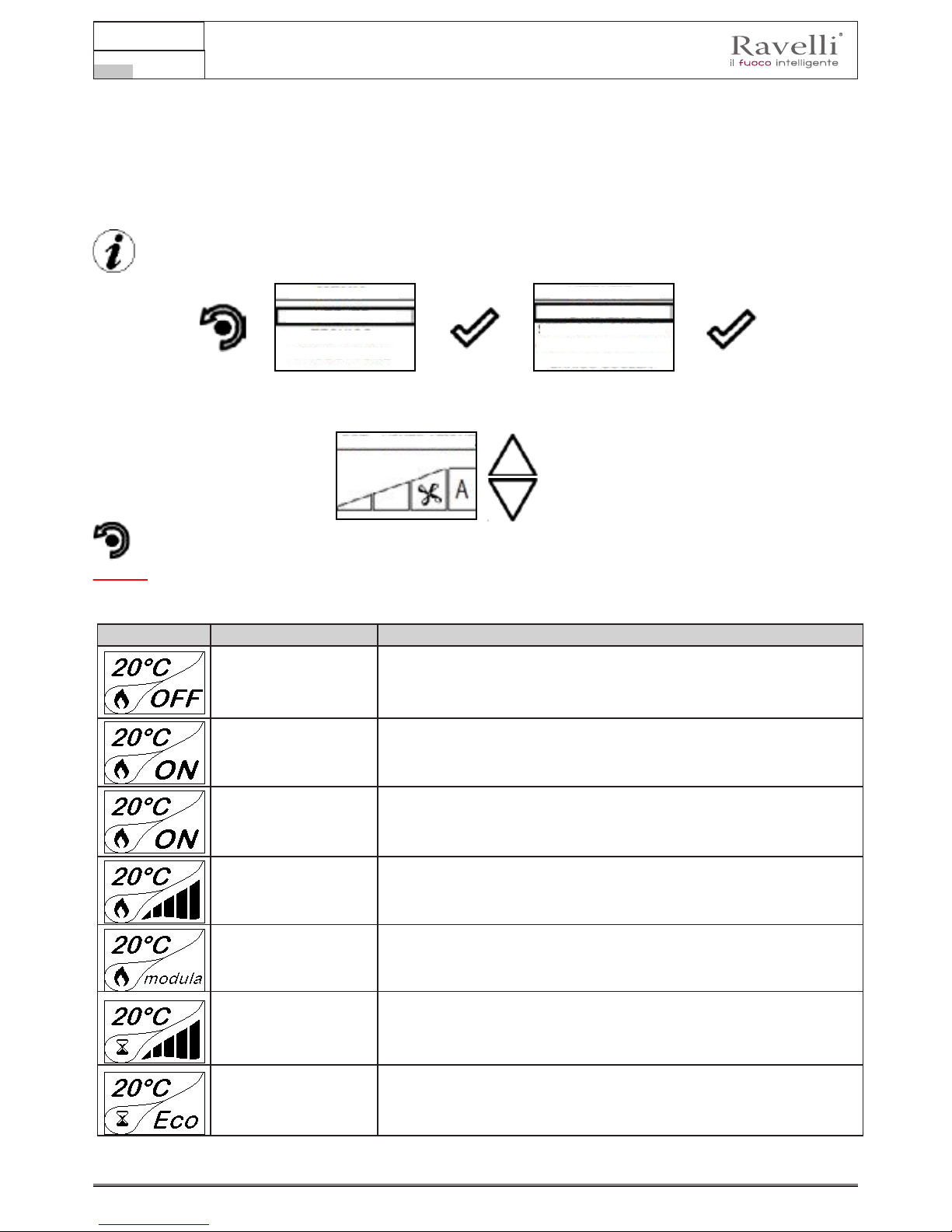
Use and maintenance manual Vela 7-9
Rev.1 20.02.18
EN
Pag.68
Manuale utente PALMARE IDRO TOUCH RADIO Manuale utente PALMARE IDRO TOUCH RADIO
Pag.32 Pag.33
Vers. 01 del 07/04/15 Vers. 01 del 07/04/15
Press the key
“conrm” to
access the
SETUP
SETTINGS
Press the key
“selection” to switch
to the function
VERSION FW.
Press the key
“conrm”
to access the function
To access the next setting, follow the steps given above or simply remove and replace the batteries.
The device resets and prompts you again to select the language you want to set.
Settings > Language
Settings > Adjust
Use the UP/DOWN keys to change the value read by the
room temperature probe installed inside the handheld
set, with respect to a reference value.
The value can vary from -10°C to 10°C.
The standard value is 0°C.
By pressing the following key you will conrm of data
and switch to the page within SETTINGS menu
The stoves equipped with ventilation system can heat the area in which are installed through the heat generated by the window and
the room temperature fan installed inside them.
Below are the messages shown on display when the stove is equipped with ventilation system.
To exit the page and return to Stand-by page, press the button repeatedly.
VENTILATION menu (function only for models in which the same is specied in the dedicate user’s manual)
Control: ventilation can be set from 0 to AUTO where 0 indicates that the same is disabled, setting from MIN to MAX enables selecting
the heat distribution speed. If set to AUTO, the ventilation follows the power set on the stove.
To exit the page and return to Stand-by page, press the button repeatedly.
The exit key shows the CHRONO menu to set other variables related to the menu functions.
The temperature read by the handheld unit controls the modulation of the stove. If you want to adjust the ventilation by
adjusting the stove, set the fan to A mode as shown in the relative chapter.
Press the key
“access menu” to
access the
MENU page
Press the key
“conrm”
to access the
USER page
Press the key
“conrm”
to quickly switch to
VENTILATION.
Press the increase/decrease keys
“increase/decrease”
to change the ventilation.
Pages displayed upon the activation of advanced layouts
By activating a layout different from the standard (layout 0), even if maintaining the same functions of the menu, the “Stand-by” page will
display all connected utilities such as the temperature of the boiler of the puffer.
Below is shown the new display mode and the function of every icon for every layout, to change the various settings.
Layout 1 (DHW Boiler + heating control)
The following layout can be used when you have a boiler that is not equipped with plate heat exchanger and you intend to buy a puffer
that should be connected to the circuit to produce hot domestic water.
In this type of circuit, room temperature is controlled however by the handheld unit which, being a radio device, acts as a remote
chronothermostat. The boiler is managed by the thermostove through a contact or immersion probe (not supplied) connected directly
to the back of the stove. Below is shown the new “Stand-by” mode.
The operation is the same as for the basic layout except for the fact that in this layout, the boiler exchanges heat directly in the
boiler (priority); when the temperature set is reached, the 3-way valve changes its position and the boiler starts exchanging heat within
If the type of system designed requires controlling the 3-way valve (diagram 1 and 3), it is necessary to purchase the
optional kit from the retailer or the authorized Ravelli dealer.
DATE-TIME
DATE-TIME
ENABLE EXT. T
ENABLE EXT. T
SEASON
SEASON
CONTRAST
CONTRAST
FW VERSION
FW VERSION
LANGUAGE
LANGUAGE
ADJUST
ADJUST
ADJUST
MENU
USER
TECHNICIAN
VENTILATION POW.
USER
POWER SETTING
CHRONOTHERMOSTAT
SCREW LOADING
SET AIR-PELLET
MANUFACTURER’S
PHASE DESCRIPTION
FINAL CLEANING The stove is in the switch off phase and the cooling phase has not been completed
yet.
SWITCH ON The heater pre-heating phase has started and the pellets start to fall into the grate.
WAITING FOR FLAME The pellets ignite and take advantage of the heat in the intake air that passes
through the incandescent heater tube.
WORK AT MAX P The stove has completed the switch on phase and runs at maximum set power
ROOM TEMPERATURE
MODULATION
The room temperature set has been reached.
THE GRATE Brazier cleaning phase is active (periodic function).
ECO STOP With Climate Comfort active, the stove switches to automatic switch-off mode
when the room temperature set is reached (see the dedicated section).
Stove phase general layout
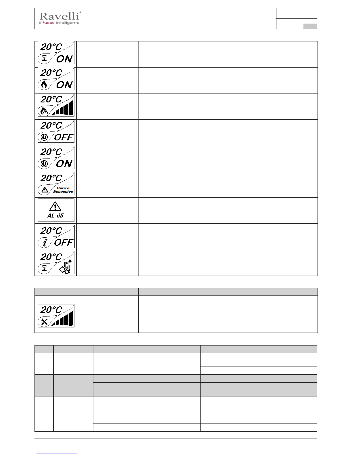
Use and maintenance manual Vela 7-9
Page 69
Rev.1 20.02.18
EN
START/RESTART WAIT Switch-on is requested but with the stove in cooling phase; once this condition is
met, it restarts automatically.
SWITCH ON RESTART The HOT restart phase is activated.
Functioning is similar to the SWITCH ON phase
HOT SMOKE The maximum fume temperature threshold has been reached. To facilitate cooling,
the stove brings the capacity to a minimum with ventilation at power level 5, leading
to a decrease in fume temperature.
OFF The stove is off
WAIT FOR PELLETS
OUT OF
When the switch-on request from ECO-STOP mode coincides with an automatic
switch-off condition (from the TIMER), the stove turns on ensuring total cleaning of
the brazier before switching to FINAL CLEANING.
INFEED SCREW
OVERFLOW
CONDITION: when the pellet setting (set pellets +5) is near the continuous load
condition.
SOLUTION: Set the value back to 0.
GENERIC ALARM The stove is in alarm state; refer to the troubleshooting chapter.
ANOMALY (general) The stove has detected an anomaly; refer to the troubleshooting chapter.
AUTOMATIC CLEANING
SYSTEM ACTIVE
For models with automatic cleaning system it indicates the operating state of the
same.
Warning Pop -Up
ANOMALY DESCRIPTION
SERVICE REQUEST The threshold value of set work hours has been reached. The symbol displayed
remains active throughout the work phase. Non-routine maintenance is required
on the stove.
Alarms (table with reference codes)
TITLE REASON SOLUTION
AL 01 BLACK OUT No voltage during work phase Press the switch off key and switch on the stove
again
If the problem persists, contact the Support Service
AL 02 K PROBE
FAILURE
The K probe is malfunctioning Contact the Support Service
The K probe is disconnected from the
electronicboard
Contact the Support Service
AL 03 OVERTEMP. K Combustion in the brazier is not optimal due to
clogging or obstructions of internal stove ducts
inside the stove
Switch off the stove, clean the brazier and the tube
bundle and adjust the combustion setting the Pellet/
Air values
Contact the Support Service
If the problem persists, contact the Support Service

Use and maintenance manual Vela 7-9
Rev.1 20.02.18
EN
Pag.70
Position of the switch,
protected by the screw cap, for
the safety reset thermostat on
the back of the stove.
AL 04 FUME EXHAUST
DAMAGED
Fume exhaust encoder is not working or is
connected incorrectly
Contact the Support Service
No power to fume extractor. Contact the Support Service
The fume extractor is blocked. Contact the Support Service
AL 05 NO SWITCH-ON The pellet tank is empty. Check for the presence of pellets in the
container.
Top up, if necessary.
Pellet calibration and suction during switch on
phase is incorrect.
Contact the Support Service
The ignition coil is faulty or positioned
incorrectly
Contact the Support Service
AL 06 PELLETS
FINISHED
The pellet tank is empty. Check for the presence of pellets in the
container.
Top up, if necessary.
The gear motor is not loading pellets. Empty the tank to see if there are any objects
inside that may prevent proper operation of the
auger.
Not enough pellets loaded Regulate pellets setting from “SET AIR/
PELLETS”
If the problem persists, contact the Support
Service
AL 07 RESETTABLE
THERMAL
BREAKER
- The manual reset thermostat has tripped
connected to the hopper (RESET THERMAL
BREAKER / Pellet door or gate is open
- Reset the thermostat by pressing the button on
the back of the stove or close the doors.
- Combustion in the grate is not optimal
due to the fact that the grate is clogged or
the inner stove ducts are clogged. (RESET
THERMAL BREAKER)
Switch off the stove, clean the brazier and the
tube bundle and adjust the combustion setting
the Pellet/Air values
Contacter le Service d’Assistance
AL 08
DEPRESSURIZATION
The ue is blocked. Check the ue is free and clean
The vacuum meter is faulty. Check the mains voltage.
AL 12 FUME EXHAUST
SYSTEM
The fume exhaust system has a loss of
performance due to fan obstruction or voltage
drop.
Check the mains voltage.
AL 14 SCREW PHASE No cable connection to power the gear motor
screw
Check the mains voltage.
AL 15 SCREW TRIAC An internal part of the electronic board that
controls the pellet infeed screw is faulty.
Check the ue is free and clean
Possible voltage drops or incorrect input
voltage stove inlet
Check the mains voltage.
AL 19 CLEANER FAILURE
(for models
equipped with
cleaner)
The cleaner did not complete the movement
and is not in the correct position
Reset the alarm and wait for the stove to switch
to SHUTDOWN mode. Cut off and power again,
the system reactivates the cleaner searching the
correct position again.
If the problem persists, contact the Support
Service

Use and maintenance manual Vela 7-9
Page 71
Rev.1 20.02.18
EN
MAINTENANCE
Safety warnings for maintenance
Maintenance of the stove must be performed at least once a year and should be planned in advance with the
Technical Assistance Service.
In some conditions, such as turning the stove on and off or inappropriate use, the combustion products can
contain small soot particles that build up in the smoke evacuation system. This can reduce the cross-section of
the smoke duct and pose a re risk.
The smoke evacuation system must be inspected and cleaned at least once a year.
The maintenance operations must be carried out when the stove is cold and with the electrical power supply
disconnected.
Before completing any maintenance operation, adopt the following precautions:
• Make sure that all stove parts are cold.
• Make sure that the ashes are completely cold.
• Always operate with equipment that is appropriate for maintenance.
• When maintenance is nished, re-install all of the dis-assembled parts before restarting operation.
! IMPORTANT
The quality of the pellet, the stove operating mode and combustion control can affect
maintenance activity frequency.
Cleaning
! IMPORTANT
Perform the cleaning operations so as to guarantee correct stove operation. The table
below lists the necessary cleaning operations required for correct stove operation.
Glass cleaning
With a cold stove, clean the glass with a cloth and glass cleaner.
Note: there are stove glass cleaning products available on the market.
Automatic cleaning system
The main characteristic of this model is the automatic cleaning of the repot. Consequently there is no more need to clean the repot
periodically or at every start of the stove.
PARTS / FREQUENCY 1 DAY 2-3 DAYS 60-90 DAYS
Combustion chamber
•
Combustion grille
•
Ash drawer
•
Glass
•
Extraction duct
•
Cleaner working (rotation 360°)
Ash-drawer: ashes are released underneath
the repot

Use and maintenance manual Vela 7-9
Rev.1 20.02.18
EN
Pag.72
! IMPORTANT
THE CLEANER EVERY TIME THE STOVE IS TURNED ON (2 ROTATIONS BY DEFAULT)
AND AFTER 6 HOURS WORKING (DEFAULT VALUE). THE TIMING FOR THIS OPERATION
(WORK/CLEANING/RESTART) TAKE ABOUT 10 MINUTES WITHOUT AFFECTING THE
HEAT EXCHANGE IN THE ROOM, BEEING ITS PARTS IN CAST IRON.
Cleaning the ash drawer
The ash drawer must be cleaned every 30 days, (depending on the amount of time the stove is used and what type of pellet is used).
To clean the ash drawer, proceed as follows:
Combustion chamber cleaning
To clean the ash drawer, proceed as follows:
step action
1
The stove requires a simple yet frequent cleaning in order to guarantee suitable yield and regular operation. Vacuum the
combustion
chamber every day using a bin ash vacuum, making sure that the ashes are completely cold.
Combustion chamber
Slide for ashes
1
2

Use and maintenance manual Vela 7-9
Page 73
Rev.1 20.02.18
EN
Cleaning the pellet tank
To clean the pellet tank, proceed as follows:
step action
1 Periodically remove the wood sawdust accumulated on the bottom of the tank, using a vacuum cleaner.
Smoke conduit cleaning
! IMPORTANT
This operation must be carried out by a Ravelli Assistance Centre.
Schedule this type of cleaning with the Ravelli Assistance Centre.
The smoke conduit must be cleaned every 3 months.
step action
1 Open the hatches.
2 Clean the ashes, eventually use a brush or similar and reassemble everything.
Note: the hatches are equipped with gaskets, therefore, before reassembling them, make sure that the gaskets are not
worn.
Note: The operation must be carried out with a cold stove, using an ash-type aspirator.
Extraordinary maintenance
Extraordinary maintenance activities must be carried out by staff from the Authorised Assistance Centre.
Do not wait for components to be deteriorated by use before proceeding with their replacement. Replace a worn
component before it is completely broken to prevent any damage caused by sudden component breakage.
PARTS / FREQUENCY 60- 90 DAYS 1 SEASON
Deep combustion chamber cleaning
•
Door gasket
•
Chimney
•
Schedule the above extraordinary maintenance activities with the Authorised Assistance Centre.
INSPECTION HATCH
GASKET
1

Use and maintenance manual Vela 7-9
Rev.1 20.02.18
EN
Pag.74
Deep combustion chamber cleaning
! IMPORTANT
This operation must be carried out by a Ravelli Assistance Centre.
Schedule this type of cleaning with the Ravelli Assistance Centre.
To clean the combustion chamber, proceed as follows:
1 Remove the vermiculite stop
2 Remove the vermiculite.

Use and maintenance manual Vela 7-9
Page 75
Rev.1 20.02.18
EN
STORAGE AND DISPOSAL
Downtime (end of season)
At the end of every season we recommend vacuuming out any ash and dust that may still be inside. It is advisable to let the pellets
burn out in the tank so that the pellet remains and sawdust can be vacuumed from the bottom and from the screw.
Disposal
Demolition and disposal of the stove is under the exclusive liability and responsibility of the owner who must do so in accordance with
the laws in force in the country of installation pertaining to safety, respect and protection of the environment.
At the end of its service life, the product must not be disposed of as household waste. It can be taken to designated separate waste
collection centres run by local administrations or to dealers who offer this service.
Disposing of the product as sorted waste avoids any negative consequences on the environment and health deriving from unsuitable
disposal and it recovers the materials that the stove is composed of in order to save considerable energy and resources.
TROUBLESHOOTING
The stove does not work
• closely follow the directions in the dedicated chapter of this manual.
• make sure that the air intake duct is not obstructed;
• make sure that the smoke evacuation system is clean and not obstructed;
• make sure the chimney is sized for the stove power;
• make sure that the air intake in the room is clear of any obstructions and that there are no other combustion appliances or
extraction hoods that create a vacuum in the room;
Difcult lighting
• closely follow the directions in the dedicated chapter of this manual;
• make sure that the air intake duct is not obstructed;
• make sure that the smoke evacuation system is clean and not obstructed;
• make sure the chimney is sized for the stove power.
• make sure that the air intake in the room is clear of any obstructions and that there are no other combustion appliances or
extraction hoods creating a vacuum in the room.
Smoke leakage
• Check the draught of the chimney.
• Check whether the seals on the door, drawer and smoke evacuation system are intact.
• Make sure there is no ash obstructing the primary air ow grille.
The glass gets dirty easily
• Only use recommended fuels.
• Check the draught of the chimney.
DATE WORK PERFORMED
MAINTENANCE

Avant-propos
Cher Client, nous vous remercions pour la conance que vous nous avez accordée en achetant l’un de nos poêles.
Nous vous invitons à lire attentivement ce manuel avant de procéder à l’installation et à l’utilisation de l’appareil, an de pourvoir
exploiter l’ensemble de ses caractéristiques en toute sécurité et de manière optimale. Il contient toutes les informations nécessaires
pour effectuer correctement l’installation, la mise en marche, l’utilisation, le nettoyage, l’entretien, etc.
Conserver ce manuel dans un endroit approprié ; ne pas mettre ce manuel de côté sans l’avoir lu.
Les installations incorrectes, les entretiens effectués incorrectement ainsi que l’usage impropre du produit dégagent le Fabricant de
toute responsabilité issue de l’usage du poêle.
Pour tout complément d’information ou en cas de besoin, veuillez contacter votre Centre d’Assistance Technique agréé par Ravelli.
Tous droits réservés. Aucune partie de ce manuel d’instructions ne peut être reproduite ou transmise avec n’importe quel moyen
électronique ou mécanique, dont la photocopie, l’enregistrement, ou tout autre système de stockage, à d'autres ns que l'usage
exclusivement personnel de l'acheteur, sans l’autorisation écrite expresse du Fabricant.

Manuel d’utilisation et d’entretien Vela 7-9
Page 78
Rév.1 20.02.18
FR
Sommaire
Avant-propos ...............................................................................................................................................................................80
IDENTIFICATION ........................................................................................................................................82
Identication du poêle ................................................................................................................................................................82
Identication du Fabricant ..........................................................................................................................................................82
Normes de référence ...................................................................................................................................................................82
GARANTIE ...................................................................................................................................................83
Certicat de garantie ...................................................................................................................................................................83
Conditions de garantie ................................................................................................................................................................83
Informations et problèmes .........................................................................................................................................................83
INFORMATIONS GÉNÉRALES ....................................................................................................................84
Fourniture et conservation ........................................................................................................................................................84
Langue .........................................................................................................................................................................................84
Symbologie utilisée dans le manuel .........................................................................................................................................84
SÉCURITÉS ...............................................................................................................................................................................84
Mises en garde générales de sécurité ......................................................................................................................................84
Risques résiduels .......................................................................................................................................................................85
DESCRIPTION DU POÊLE ............................................................................................................................ 85
Usage prévu ................................................................................................................................................................................85
Usage incorrect raisonnablement prévisible ...........................................................................................................................85
Obligations et interdictions .......................................................................................................................................................85
CARACTÉRISTIQUES TECHNIQUES ..........................................................................................................86
Les majoliques (le cas échéant) .................................................................................................................................................86
Combustibles interdits ................................................................................................................................................................86
Dimensions .................................................................................................................................................................................87
Schéma technique .......................................................................................................................................................................87
Composants principaux ............................................................................................................................. 90
TRANSPORT ET INSTALLATION ................................................................................................................ 90
Mises en garde de sécurité pour le transport et l’installation ................................................................................................90
Emballage ....................................................................................................................................................................................91
Préparations pour le système d’évacuation des fumées .......................................................................................................91
Sortie de toit ................................................................................................................................................................................91
Terminal de cheminée ................................................................................................................................................................92
Installation ...................................................................................................................................................................................92
Pré-requis du local prévu pour l’installation ...........................................................................................................................92
Exemples d’installation ...............................................................................................................................................................94
Les majoliques (le cas échéant) .................................................................................................................................................96
Raccordements ...........................................................................................................................................................................97
Raccordement à la sortie de toit ...............................................................................................................................................97
Schéma électrique .......................................................................................................................................................................97
Test d’essai et mise en service .................................................................................................................................................98
Commandes et utilisation ...........................................................................................................................................................98
Insertion des batteries dans le portable: ..................................................................................................................................98
Initialisation du portable .............................................................................................................................................................98
Description du display ................................................................................................................................................................99
Conguration de la date et de l’heure .....................................................................................................................................100
PROCÉDURES D’UTILISATION .........................................................................................................................................101
Vérications avant l’allumage .................................................................................................................................................101
Allumer et éteindre l’appareil ...................................................................................................................................................101
Que faire en cas d’alarme “Ignition” .......................................................................................................................................101
Allumage de l’appareil ..............................................................................................................................................................102
Confort clima .............................................................................................................................................................................103
Description des fonctions au menu .........................................................................................................................................104
Chrono-thermostat ...................................................................................................................................................................104
Etat poêle ...................................................................................................................................................................................105
Réglages > Activez le thermostat ............................................................................................................................................105
Réglages .....................................................................................................................................................................................106
Schéma synthétique phases du poêle ....................................................................................................................................107
Pop up de signalisation ...........................................................................................................................................................108
Alarmes (tableau codes de référence) .....................................................................................................................................108
Nettoyage de la vitre ................................................................................................................................................................110
Systeme automatique de nettoyage ........................................................................................................................................110
Nettoyage du tiroir à cendre ....................................................................................................................................................111
Nettoyage du conduit de fumée ..............................................................................................................................................112
Entretien extraordinaire ............................................................................................................................................................112
Mise au repos (en n de saison) .............................................................................................................................................113
Élimination ................................................................................................................................................................................113
ÉTUDE DES CAS DES PANNES ................................................................................................................. 114
Le poêle ne fonctionne pas .....................................................................................................................................................114
Allumage difcile .......................................................................................................................................................................114
Fuite de fumée ...........................................................................................................................................................................114
La vitre se salit facilement. .......................................................................................................................................................114

Manuel d’utilisation et d’entretien Vela 7-9
Page 79
Rév.1 20.02.18
FR
IDENTIFICATION
Identification du poêle
Type de produit POÊLE À GRANULÉS
Modèle
Vela 7 C
Vela 7 N
Vela 7 V
Vela 9 C
Vela 9 N
Vela 9 V
Identification du Fabricant
Fabricant Aico S.p.A.
Via Kupfer, 31 - 25036 Palazzolo sull’Oglio (BS) ITALY
Tél. +39 030 7402939
Fax +39 030 7301758
www.ravelligroup.it
info@ravelligroup.it
Normes de référence
Les poêles Vela 7- 9 visés dans ce manuel sont conformes au règlement
305/2011 RÈGLEMENT DES PRODUITS DE CONSTRUCTION
et respectent la norme harmonisée suivante :
EN 14785; EN 55014-1; EN 55014-2; EN 61000-3-2; EN 61000-3-3; EN 60335-1; EN 60335-2-102; EN 62233; EN 50581; ETSI
EN 300220-1
Toutes les règlementations locales, y compris celles référées aux normes nationales et européennes doivent être respectées en
installant l’appareil.

Manuel d’utilisation et d’entretien Vela 7-9
Page 80
Rév.1 20.02.18
FR
GARANTIE
Certicat de garantie
La société Ravelli vous remercie de la confiance que vous lui avez accordée en achetant l’un de ses produis et elle invite l’acheteur à :
• consulter les instructions pour l’installation, l’utilisation et l’entretien du produit ;
• consulter les conditions de garantie reportées ci-après.
Conditions de garantie
La garantie au Client est reconnues par le Revendeur selon les termes de la loi. Le coupon de garantie doit être rempli entièrement.
Le Client est tenu de vérifier la compilation de la garantie et l’expédition de la part du Revendeur (ou bien il doit s’occuper lui-même de
l’expédition) du coupon de garantie et de la copie du ticket de caisse/facture dans les 8 jours à compter de la date d’achat.
Le coupon de garantie et la copie du ticket de caisse/ facture doivent être envoyés à l’adresse suivante :
Ravelli chez Aico SpA
Via Kupfer, 31
25036 Palazzolo s/O
Brescia (ITALIE)
Le Revendeur reconnaît la garantie à condition qu’il n’y ait eu aucune manipulation du produit et uniquement si l’installation a été effectuée
conformément à la règlementation et en suivant les prescriptions du Fabricant.
La garantie limitée couvre les défauts des matériaux de fabrication à condition que le produit n’ait pas subi de ruptures causées par un
usage incorrect, la négligence, un branchement incorrect, des manipulations frauduleuses, des erreurs d’installation.
La garantie est annulée même si une seule prescription reportée dans ce manuel n’est pas respectée.
Ne sont pas couverts par la garantie :
• les réfractaires de la chambre de combustion ;
• la vitre de la porte ;
• les joints ;
• la peinture ;
• la grille de combustion en acier inoxydable ou en fonte ;
• les majoliques en couleurs ;
• tout dommage causé par une installation et/ou une utilisation incorrecte du poêle et/ou des négligences de la part du consommateur.
L’utilisation de granulés de mauvaise qualité ou de tout autre combustible non autorisé risque d’endommager des composants du produit
en entraînant la cessation de la garantie sur ceux-ci et la responsabilité annexée du Fabricant.
Il est donc conseillé d'utiliser du granulés de bonne qualité conforme aux exigences énumérées dans le chapitre dédié.
Tous les dommages dus au transport ne sont pas reconnus ; il est donc conseillé de vérifier soigneusement la marchandise à la réception
et de prévenir immédiatement le Revendeur de tout dommage.
Informations et problèmes
Les Revendeurs agréés Ravelli bénéficient d’un réseau de Centres d’Assistance Technique formés afin de satisfaire les besoins de
leurs Clients. Pour toute information ou demande d’assistance, le Client doit contacter son propre Revendeur ou un Centre d’Assistance
Technique.

Manuel d’utilisation et d’entretien Vela 7-9
Page 81
Rév.1 20.02.18
FR
INFORMATIONS GÉNÉRALES
Fourniture et conservation
Le manuel est fourni au format papier.
Conserver ce manuel fourni avec le poêle de manière à ce que l’utilisateur puisse facilement le consulter.
Le manuel est une partie intégrante à des ns de sécurité, ainsi :
• il doit être conservé intact (dans toutes ses parties). En cas de perte ou d’endommagement, il faut immédiatement en demander
un autre exemplaire.
• il doit accompagner le poêle jusqu’à sa démolition (même en cas de déplacements, de vente, de location, de bail, etc.).
Le Fabricant décline toute responsabilité en cas d’usage impropre du poêle et/ou de dommages causés suite à des opérations qui
ne sont pas visées dans la documentation technique.
Langue
Le manuel original a été rédigé en italien.
Toute traduction dans des langues supplémentaires doit être effectuée à partir des instructions originales.
Le Fabricant est responsable des informations contenues dans les instructions originales ; les traductions dans d’autres langues ne
pouvant pas être complètement vériées, en cas d’incohérence il faut respecter le texte rédigé dans la langue originale ou contacter
notre Service documentation technique.
Symbologie utilisée dans le manuel
symbole dénition
! IMPORTANT
Symbole utilisé pour identier des informations particulièrement importantes dans le
manuel. Les informations concernent aussi la sécurité des utilisateurs concernés par
l’utilisation du poêle.
Symbole utilisé pour identier des mises en garde importantes pour la sécurité de
l’utilisateur et/ou du poêle.
SÉCURITÉS
Mises en garde générales de sécurité
! IMPORTANT
Lire attentivement ce manuel d’instructions avant d’installer et d’utiliser le poêle. Le
non-respect des prescriptions de ce manuel peut entraîner la déchéance de la garantie et/
ou entraîner des dommages matériels et/ou personnels.
L’installation, l’inspection de l’installation, la vérification du fonctionnement et l’étalonnage initial du poêle ne
doivent être effectuées que par un personnel qualié et autorisé.
Le poêle doit être raccordé à une sortie de toit individuelle qui puisse garantir le tirage déclaré par le Fabricant et
respecter les normes d’installation prévues dans le lieu d’installation.
Le local où le poêle est installé doit être doté d’une prise d’air.
Ne pas utiliser l’appareil comme si c’était un incinérateur ou d’une manière autre que celle pour laquelle il a été
conçu.
Ne pas utiliser de combustible autre que de
granulés du
bois. Il est strictement interdit d’utiliser des combustibles
liquides.
Il est interdit de faire fonctionner le poêle si la porte ou le tiroir à cendre est ouvert ou si la vitre est cassée. Il n’est
autorisé d’ouvrir la porte que pendant l’allumage et les opérations de rechargement.
Ne pas toucher les surfaces chaudes du poêle sans porter les moyens de protection adéquats, de manière à éviter
les brûlures. Quand il est en marche, les surfaces extérieures atteignent des températures élevées au toucher.
Il est interdit d’apporter des modications non autorisées au poêle.
Avant d’utiliser le poêle, il faut connaître l’emplacement et la fonction des commandes.
En cas d’incendie de la sortie de toit, appeler les Sapeurs Pompiers.
N’utiliser que des pièces de rechange originales. Toute altération frauduleuse et/ou toute substitution non
autorisée par Ravelli peut entraîner des dangers pour l’intégrité corporelle de l’utilisateur.

Manuel d’utilisation et d’entretien Vela 7-9
Page 82
Rév.1 20.02.18
FR
Dans le cas de conditions météorologiques particulièrement négatif, des systèmes de sécurité pourraient porter
à l’arrêt de la poêle. Dans tous les cas, ne pas désactiver les systèmes de sécurité.
Risques résiduels
La conception du poêle a été effectué de manière à garantir les exigences essentielles de sécurité pour l’opérateur.
La sécurité, autant que possible, a été intégrée dans la conception et la construction du poêle.
Le manuel fournit une description du risque et de la zone ou de la partie soumise au risque résiduel (à moins qu’il ne s’agisse d’un
risque qui concerne l’ensemble du poêle). Il fournit aussi des informations procédurales concernant la façon d’éviter le risque et
l’usage correct des équipements de protection individuelle prévus et prescrits par le Fabricant.
risque résiduel description et informations procédurales
Risque de brûlure Lorsque le poêle est en marche, il peut atteindre des températures élevées au toucher, surtout sur les
surfaces extérieures. Prêter attention pour éviter toute brûlure et utiliser éventuellement les outils spéciques.
Porter le gant fourni pour ouvrir couvercle des granulés an d’effectuer le rechargement du poêle.
DESCRIPTION DU POÊLE
Usage prévu
L’appareil en question est prévu pour:
opération combustible admissible combustible interdit environnement
Chauffage par irradiation
et par convection, par la
combustion de:
Granulés de bois Tout autre combustible autre
que celui admissible.
Domestique ou commercial
Le poêle est conçu et construit pour travailler en toute sécurité si:
• il est installé en respectant les normes spéciques par un personnel qualié;
• il est employé dans les limites déclarées sur le contrat et sur ce manuel;
• les procédures du mode d’emploi sont respectées;
• l’entretien ordinaire est effectué dans les délais et selon les procédures indiqués;
• l’entretien extraordinaire est réalisé au bon moment, en cas de besoin;
• les dispositifs de sécurité ne sont pas ôtés et/ou contournés
! IMPORTANT
Ce poêle doit être destiné à l’usage pour lequel il a été expressément réalisé.
Usage incorrect raisonnablement prévisible
L’usage incorrect raisonnablement prévisible est énuméré ci-après:
• l’utilisation du poêle comme si c’était un incinérateur;
• l’utilisation du poêle avec un combustible autre que du bois à brûler;
• l’utilisation du poêle avec des combustibles liquides;
• l’utilisation du poêle avec la porte ouverte ou sans le tiroir à cendre.
Tout autre usage de l’appareil par rapport à ce qui prévu doit être préalablement autorisé par écrit par le Fabricant. En l’absence
de cette autorisation écrite, l’usage doit être considéré comme un « usage impropre ». Le Fabricant décline toute responsabilité
contractuelle et extra-contractuelle en cas de dommages corporels ou matériels découlant d’erreurs d’installation, de réglage,
d’entretien et d’usages impropres.
Obligations et interdictions
Obligations
L’utilisateur doit:
• lire ce manuel d’instructions avant d’accomplir toute opération sur le poêle;
• l’appareil peut être utilisé par des enfants de plus de 8 ans et par des personnes ayant des capacités physiques, sensorielles
ou mentales réduites ou n’ayant pas l’expérience ou les connaissances nécessaires, à condition qu’ils soient surveillés;
• ne pas utiliser le poêle de manière impropre, c’est-à-dire pour des usages autres que ceux indiqués au paragraphe « USAGE
PRÉVU »;
• il est strictement interdit d’utiliser des combustibles liquides inammables pour l’allumage;
• laisser les objets qui ne résistent pas à la chaleur et/ou inammables à une distance de sécurité opportune;
• n’alimenter le poêle qu’avec du granulés ayant les caractéristiques décrites dans ce manuel;
• raccorder le poêle à une sortie de toit conforme aux normes;
• raccorder le poêle à l’aspiration à l’aide d’un tuyau ou d’une prise d’air de l’extérieur;
• il faut toujours effectuer les interventions d’entretien lorsque le poêle est éteint et froid;
• effectuer les opérations de nettoyage en suivant la fréquence indiquée dans ce manuel;
• utiliser les pièces de rechange originales conseillées par le Fabricant.
Interdictions
L’utilisateur ne doit:
• ôter ou modier les dispositifs de sécurité sans autorisation;
• accomplir de sa propre initiative des opérations ou des manœuvres qui ne relèvent pas de ses compétences ou susceptibles de
compromettre sa sécurité ou celle d’autrui;

Manuel d’utilisation et d’entretien Vela 7-9
Page 83
Rév.1 20.02.18
FR
• utiliser des combustibles autres que du granulés à brûler et que ceux indiqués pour l’allumage;
• utiliser le poêle comme si c’était un incinérateur;
• utiliser des substances inammables ou explosives à proximité du poêle, pendant qu’il fonctionne;
• utiliser le poêle avec la porte ouverte et/ou la vitre endommagée ou cassée;
• fermer en aucun cas les ouvertures d’entrée de l’air comburant et de sortie des fumées;
• utiliser le poêle pour faire sécher du linge;
• remplacer ou modier certains composants du poêle.
CARACTÉRISTIQUES TECHNIQUES
Vela 7 Vela 9 U
Ø tuyau de sortie des fumées 80 80 mm
Volume max. de chauffage 165 195 m
3
Puissance thermique d’entrée 3,4 - 7,4 3,4 - 9,1 kW
Puissance thermique 3,3 - 6,9 3,3 - 8,3 kW
Consommation horaire réd. / nom. 0,71 - 1,53 0,71 - 1,87 kg/h
Consommation d’énergie nominale. 360 360 W
Alimentation 230 - 50 230 - 50 Hz - V
Capacité du réservoir 20 22 kg
Autonomia min. - max. 13 - 28 12 - 28 h
Rendement - réd. / nom. 95,5 - 92,9 95,5 - 90,6 %
CO à 13 % d’O
2
0,018 - 0,004 0,018 - 0,004 %
Débit des fumées 2,9 - 4.6 2,9 - 5,7 g/s
Tirage minimum 10 - 0,1 10 - 0,1 Pa - mbar
Température des fumées 73 - 129 73 - 163 °C
Les données ci-dessus sont indicatives et non contraignantes et peuvent varier selon le type et la qualité du granulés de bois utilisé.
La société Ravelli se réserve le droit d’apporter toute modication visant à améliorer les performances des produits.
Caractéristiques du combustible
Les granulés de bois sont un combustible qui se compose de sciure de bois pressée, souvent obtenue à partir des restes de la menuiserie.
Le matériau utilisé ne doit contenir aucune substance étrangère comme de la colle, de la peinture ou des substances synthétiques par
exemple.
La sciure de bois, après avoir été séchée et nettoyée des impuretés, est pressée à travers une matrice à trous : en raison de la haute
pression, la sciure de bois chauffe en activant les liants naturels du bois ; les granulés conservent ainsi sa forme même sans ajout de
substances artificielles. La densité des granulés de bois varie selon le type de bois et peut dépasser de 1,5 à 2 fois celle du bois naturel.
Les granulés ont un diamètre de 6 mm et une longueur qui varie entre 10 et 40 mm.
Leur densité est environ 650 kg/m3. En raison de leur faible teneur en eau (< 10 %), ils ont un contenu énergétique élevé.
La norme UNI EN ISO 17225-2:2014 (qui remplace la norme EN PLUS) définit la qualité des granulés en différenciant trois classes : A1,
A2 et B.
Ravelli recommande l’utilisation des granulés de bois certifiés classe A1 et A2 conformément à la norme EN ISO 17225-2:2014, ou certifiés
DIN PLUS (classe plus restrictive que la classe A1) ou ONORM M 7135.
Les granulés, qui peuvent être de couleur claire ou foncée, sont normalement conditionnés dans des sacs qui reportent le nom du
producteur, les principales caractéristiques et la classification selon les normes.
! IMPORTANT
Les granulés doivent être transportés et stockés dans un endroit sec. Vu qu’ils gonflent
au contact de l’humidité en devenant inutilisables, il est nécessaire de les protéger de
l’humidité aussi bien pendant le transport que pendant le stockage.
Garder les combustibles et toute autre matière inflammable à une distance adéquate.
Les majoliques (le cas échéant)
Les majoliques colorées utilisées pour le revêtement sont travaillées artisanalement et sont nies à la main.
C’est la raison pour laquelle de légères imperfections de surface telles que les ombres et les brèches doivent être considérées
comme des caractéristiques qui font de chaque majolique un exemplaire unique.
Les majoliques colorées sont un matériau délicat ; il est conseillé de les manipuler avec soin pendant le nettoyage
et d’éviter les coups car elles risquent de s’endommager.
Combustibles interdits
Il est conseillé de ne pas utiliser les matériaux suivants :
• du bois
• du bois traité (bois peint, laqué, collé, etc.)
• de la sciure et des copeaux de bois
• des combustibles liquides

Manuel d’utilisation et d’entretien Vela 7-9
Page 84
Rév.1 20.02.18
FR
Schéma technique Vela 7 N - Vela 7 V
Les données ci-dessus, qui sont indicatives et non pas contraignantes, peuvent varier selon le type de granules du bois utilisé. La société Elledi se réserve le droit d’apporter toute modication visant à améliorer les performances de ses produits.
• du charbon ou d’autres combustibles fossiles
• du plastique et produits dérivés
• du papier et du carton traités
• des déchets
• des combustibles pouvant dégager des substances toxiques ou polluantes.
L’utilisation de ces combustibles est non seulement interdite parce qu’elle entraîne l’émission de substances nocives et polluantes,
mais elle cause aussi une détérioration plus rapide du poêle et une accumulation de saleté dans le poêle et dans le système
d’évacuation des fumées, ce qui entraîne une baisse des performances et de la sécurité de l’appareil.
Les gaz produits par ces combustibles sont dangereux pour l’environnement et pour votre santé !
L’utilisation de combustible non conforme aux indications susmentionnées fait déchoir la garantie.
Dimensions
Vela 7 C
Vela 7 N
Vela 7 V
Vela 9 C
Vela 9 N
Vela 9 V
Unité de
mesure
Hauteur 1108 1108 mm
Largeur 520 520 mm
Profondeur 565 565 mm
Poids à vide 185 180 kg
515
1060
562
216
258
128
419
80 (USCITA FUMI)
50 (ENTRATA ARIA)
562
216
258
128
419
80 (USCITA FUMI)
50 (ENTRATA ARIA)
Ø50 (AMENÉE D’AIR)
Ø80 (
SORTIE DES FUMÉES
)

Manuel d’utilisation et d’entretien Vela 7-9
Page 85
Rév.1 20.02.18
FR
Les données ci-dessus, qui sont indicatives et non pas contraignantes, peuvent varier selon le type de granules du bois utilisé. La société Elledi se réserve le droit d’apporter toute modication visant à améliorer les performances de ses produits.
SCHÉMA TECHNIQUE
VELA 7 C
SCHÉMA TECHNIQUE
VELA 9 N - VELA 9 V
SCHÉMA TECHNIQUE
VELA 9 C
515
1060
562
216
258
128
419
60 (CANALIZZATA)
50 (ENTRATA ARIA)
80 (USCITA FUMI)
160
337
562
216
258
128
419
60 (CANALIZZATA)
50 (ENTRATA ARIA)
80 (USCITA FUMI)
160
337
Ø50 (AMENÉE D’AIR)
Ø60 CANALISATION
562
419
216
128
258
50 (ENTRATA ARIA)
80 (USCITA FUMI)
516
1109
562
419
216
128
258
50 (ENTRATA ARIA)
80 (USCITA FUMI)
Ø50 (AMENÉE D’AIR)
Ø80 (
SORTIE DES FUMÉES
)
1109
515
562
216
419
258
128
337
160
60 (CANALIZZATA)
50 (ENTRATA ARIA)
80(USCITA FUMI)
562
216
419
258
128
337
160
60 (CANALIZZATA)
50 (ENTRATA ARIA)
80(USCITA FUMI)
Ø50 (AMENÉE D’AIR)
Ø80 (
SORTIE DES FUMÉES
)
Ø60 CANALISATION

Manuel d’utilisation et d’entretien Vela 7-9
Page 86
Rév.1 20.02.18
FR
Composants principaux
élément
A Grille pour le passage de
l’air
B Porte
C Tiroir à cendre
D Couvercle des granulés
E Plaque d’inspection
F Chambre de combustion
G Glissière pour les cendres
H Brasero
TRANSPORT ET INSTALLATION
Mises en garde de sécurité pour le transport et l’installation
! IMPORTANT
L’installation du poêle doit être effectuée par un technicien qualié, tenu de délivrer
une déclaration de conformité de l’équipement à l’acheteur, en assumant l’entière
responsabilité de l’installation nale et du fonctionnement correct du poêle.
! IMPORTANT
Le lieu d’installation du poêle doit être choisi de manière à ce que la chaleur générée
puisse se répandre uniformément dans les pièces que vous voulez chauffer.
Le poêle doit être raccordé à une sortie de toit individuelle qui puisse garantir le tirage déclaré par le Fabricant et
respecter les normes d’installation prévues dans le lieu d’installation.
Le local où le poêle est installé doit être doté d’une prise d’air.
La prise d’air doit être installée de manière à ne pas pouvoir être bloquée.
Le Fabricant décline toute responsabilité en cas d’installation non conforme aux lois en vigueur, de renouvèlement incorrect de l’air
dans les locaux et d’usage impropre de l’appareil.
Il faut notamment que:
• l’appareil soit raccordé à un système d’évacuation des fumées opportunément dimensionné an de garantir le tirage déclaré par
le Fabricant, étanche et qui respecte les distances des matières inammables;
• il y ait une prise d’air comburant conforme au type de produit installé;
• aucun appareil à combustion ou dispositif installé ne mettre le local d’installation du poêle en dépression;
• les distances de sécurité des matériaux inammables soient respectées.
La vérication de la compatibilité de l’installation doit précéder toute autre opération de montage ou de pose.
A
D
B
C
E
F
H
G

Manuel d’utilisation et d’entretien Vela 7-9
Page 87
Rév.1 20.02.18
FR
! IMPORTANT
Il se peut que les règlements administratifs locaux, les prescriptions particulières des
autorités qui concernent l’installation d’appareils à combustion, la prise d’air et le dispositif
d’évacuation des fumées changent en fonction de la région ou du pays. Vérier auprès
des autorités locales s’il existe des prescriptions de loi plus strictes que les indications
du manuel.
Emballage
Après avoir reçu le poêle, contrôler qu’il
• corresponde au modèle acheté et;
• qu’il n’ait pas d’endommagements dus au transport.
Toute réclamation doit être communiquée au transporteur (même sur le document d’accompagnement) au moment de la réception.
Vérier la capacité portante du plancher avant de manutentionner et de mettre le poêle en place.
Pour la manutention du poêle emballé, suivre la procédure suivante:
1 Placer les fourches du transpalette dans les logements spécifiques sous la palette en bois.
2 Soulever lentement.
3 Amener le poêle près de l’endroit préchoisi pour l’installation.
Le poêle doit toujours être manutentionné à la verticale. Il faut faire particulièrement attention an que la porte et
sa vitre soient protégées des collisions mécaniques qui compromettent leur intégrité.
.
Pour le déballage du poêle, suivre la procédure décrite ci-après:
1 Couper les bandes de cerclage métalliques et ôter le châssis de renfort en bois posé sur le carton.
2 Soulever lentement le carton.
3 Retirer tout emballage en film à bulles ou réalisé dans des matériaux similaires.
4 Ôter le poêle de la palette et placer l’appareil à l’endroit préchoisi en veillant à ce qu’il soit conforme aux indications.
! IMPORTANT
C’est le client nal qui est chargé de l’élimination de l’emballage, conformément aux lois
en vigueur dans le pays d’installation.
Préparations pour le système d’évacuation des fumées
Prêter attention à la réalisation du système d’évacuation des fumées et respecter les normes en vigueur dans le
pays d’installation du poêle.
! IMPORTANT
Le Fabricant décline toutes les responsabilités si elles sont attribuables à un système
d’évacuation des fumées mal dimensionné et qui n’est pas conforme aux normes.
Canal de fumée et raccords
Les « canaux de fumée » sont les tuyaux qui relient l’appareil à combustion à la sortie de toit.
Il faut appliquer les prescriptions suivantes:
• respecter la norme du produit EN 1856-2;
• les sections horizontales doivent avoir une pente minimum de 3 % vers le haut;
• la longueur de la section horizontale doit être minimale et sa projection dans le plan ne pas dépasser 2 mètres;
• les changements de direction ne doivent pas avoir d’angle supérieur à 90° (courbes recommandées de 45°);
• le nombre de changements de direction dont celui pour l’introduction dans la sortie de toit ne doit pas être supérieur à 3;
• la section doit avoir un diamètre constant et identique de la sortie du foyer jusqu’au raccord dans la sortie de toit;
• il est interdit d’utiliser des tuyaux métalliques exibles et en brociment;
• les canaux de fumée ne doivent pas traverser de pièces où l'installation d’appareils à combustion est interdite.
Dans tous les cas, les canaux de fumée doivent être étanches aux produits de la combustion et des condensations, ainsi qu’isolés
s'ils passent à l'extérieur de la pièce où ils sont installés.
Le montage de dispositifs de réglage manuel du tirage est interdit.
! IMPORTANT
Il faut obligatoirement réaliser une première section verticale du conduit de fumée d’au
moins 1 m pour assurer la bonne expulsion des fumées.
Sortie de toit
La sortie de toit est un élément particulièrement important pour le fonctionnement correct du poêle.

Manuel d’utilisation et d’entretien Vela 7-9
Page 88
Rév.1 20.02.18
FR
La sortie de toit doit être dimensionnée de manière à assurer le tirage déclaré par le Fabricant.
Ne pas raccorder le poêle à une sortie de toit collective.
Pendant la réalisation de la sortie de toit, il faut appliquer les prescriptions suivantes:
• respecter la norme du produit EN 1856-1;
• il doit être réalisé avec des matériaux appropriés pour garantir la résistance aux contraintes mécaniques, chimiques et thermiques
ordinaires et il doit être bien isolé an de limiter la formation de condensation;
• il doit avoir un développement principalement vertical et sans aucun étranglement sur toute sa longueur;
• il doit être correctement espacé à l’aide d’une gaine d’air et isolé des matériaux inammables;
• les changements de direction doivent être au maximum 2 et leur angle ne doit pas dépasser 45°;
• la sortie de toit à l’intérieur de l’habitation doit, de manière générale, être isolée et elle peut être insérée dans une cour, à
condition qu’elle respecte les normes relatives au tubage;
• le conduit de fumée doit être raccordé à la sortie de toit à l’aide d’un raccord en « T » ayant une chambre de récupération qu’il
est possible d’inspecter pour les résidus de la combustion et surtout pour la récupération de la condensation.
! IMPORTANT
Il est conseillé de vérifier, sur les données nominales de la sortie de toit, les distances de
sécurité qu’il faut respecter en présence de matériaux combustibles et le type de matériau
isolant à utiliser.
Utiliser des tuyaux étanches avec des joints étanches.
Il est interdit d’utiliser l’évacuation au mur ou vers des espaces fermés et toute autre forme d’évacuation non
prévue par les normes en vigueur dans le pays d’installation (N.B : en Italie, seule l’évacuation par le toit est
autorisée).
Terminal de cheminée
Le terminal de cheminée, c’est-à-dire la partie nale de la sortie de toit, doit satisfaire aux caractéristiques suivantes:
• la section de sortie des fumées doit être au moins le double de la section intérieure de la cheminée;
• éviter la pénétration de l’eau ou de la neige;
• xer la sortie des fumées même en cas de vent (terminal de cheminée anti-vent);
• la hauteur de sortie doit se trouver en dehors de la zone de reux (consulter les normes nationales et locales pour identier la
zone de reux);
• être toujours construit loin des antennes ou des paraboles, il ne doit jamais être utilisé comme support.
Installation
Pour installer et utiliser l’appareil, il faut respecter toutes les lois et les règlements locaux, nationaux et européens.
L’installation du poêle et la préparation des travaux de maçonnerie doivent respecter les normes en vigueur dans
le pays d’installation (ITALIE = UNI 10683).
! IMPORTANT
Les opérations d’installation doivent être effectuées par un technicien qualié et/
ou autorisé par le Fabricant. Le personnel chargé de l’installation est tenu de délivrer
une déclaration de conformité de l’équipement à l’acheteur, en assumant l’entière
responsabilité de l’installation dénitive et du bon fonctionnement qui s’ensuit du produit
installé.
Ravelli n’assume aucune responsabilité en cas de non-respects de ces précautions.
Pré-requis du local prévu pour l’installation
Le local d’installation du poêle doit être sufsamment ventilé. Pour satisfaire à ce pré-requis, il faut équiper le local d’une prise d’air
qui communique avec l’extérieur.
! IMPORTANT
Le local d’installation doit être muni d’une prise d’air ayant une section libre d’au moins
100 cm2.
! IMPORTANT
En cas d’installation en présence d’autres appareils de combustion ou d’un appareil de
VMC, il faut vérier le fonctionnement correct de l’appareil.
Le poêle doit être placé à l’intérieur de pièces habitatives. Il ne doit jamais être installé à l’extérieur. Le volume du local d’installation
doit être adapté à la puissance de l’appareil et en règle générale, il doit être supérieur à 15 m3.

Manuel d’utilisation et d’entretien Vela 7-9
Page 89
Rév.1 20.02.18
FR
ATTENTION !
Lorsqu’ils sont utilisés dans la même pièce ou le même espace que le poêle, les ventilateurs d’extraction comme
les hottes d’aspiration peuvent causer des problèmes de fonctionnement du poêle.
Le poêle doit être installé sur un plancher ayant une capacité portante adéquate. Si la position actuelle n’est
pas conforme à ce pré-requis, il faut prendre des mesures appropriées en utilisant, par exemple, une plaque de
répartition de la charge).
ATTENTION !
Il faut prévoir une isolation adéquate si la surface est constituée d’un matériau inflammable.
Si les murs latéraux adjacents au poêle sont réalisés dans un matériau inammable, il faut placer le poêle à au moins 30 cm.
Distance minimale des matériaux inammables
R côté droit 150 mm
L côté gauche 150 mm
B arrière 100 mm
A avant > 800 mm
Si le plancher sur lequel le poêle est en appui est réalisé dans un matériau inammable, il est conseillé de prévoir une isolation
adéquate. Il est impossible de stocker des objets et des pièces sensibles à la chaleur ou inammables à proximité du poêle ; en règle
générale, il faut laisser ces objets à 100 cm minimum du point d’encombrement le plus extérieur de l’appareil.
L’installation du poêle doit garantir un accès facile pour le nettoyage de l’appareil en question, des conduites des gaz d’échappement
et de la sortie de toit.
L AR B

Manuel d’utilisation et d’entretien Vela 7-9
Page 90
Rév.1 20.02.18
FR
Exemples d’installation
Ce type d’installation (voir la Fig. 1) exige une sortie de toit
isolée bien que l’ensemble du conduit soit monté à l’intérieur de
l’habitation. La structure doit en outre être insérée dans un atrium
convenablement ventilé.
Dans la partie inférieure de la sortie de toit, il y a un couvercle
d’inspection convenablement isolé du vent et de la pluie.
Protection de la pluie
Fig.1
Grille pour le passage de l’air
dans l’atrium avec une ouverture pour l’inspection dans la
sortie de toit
Cavedio
Raccord en T pour la condensation
Sortie de toit isolée
Comme premier tronçon initial, il est interdit d’installer un coude
à 90°, car la cendre bloquerait le passage des fumées en peu
de temps, en causant des problèmes de tirage du chaudière.
(Voir la Fig. 2)
Cendres déposées dans
le coude à 90°
NON
Il est possible d’utiliser un conduit d’évacuation des fumées
existant ou une gaine technique au moyen d’une canalisation.
Pour ce type d’installation, il faut respecter les normes
concernant les systèmes d’évacuation des fumées canalisés.
Un raccord de type en « T » a été monté dans la partie inférieure
de la sortie de toit à l’intérieur de l’habitation ; un autre a été
monté à l’extérieur de manière à ce que le tronçon à l’extérieur
puisse être inspecté.
Il est interdit d’installer deux coudes à 90°, car la cendre
bloquerait le passage des fumées en peu de temps, en causant
des problèmes de tirage du chaudière. (Voir la Fig. 2)
Canal de fumée:
utilisation d’un tuyau
non isolé
Raccord en T T
Conduit d’évacuation des
fumées isolé
Fig.3
Protection de la pluie
Raccord en T pour la
condensation
Chambre de récupération
des cendres de combustion
+ bouchon condensation
Prise d’air à
l’extérieur
Prise d’air à
l’extérieur
Prise d’air à
l’extérieur
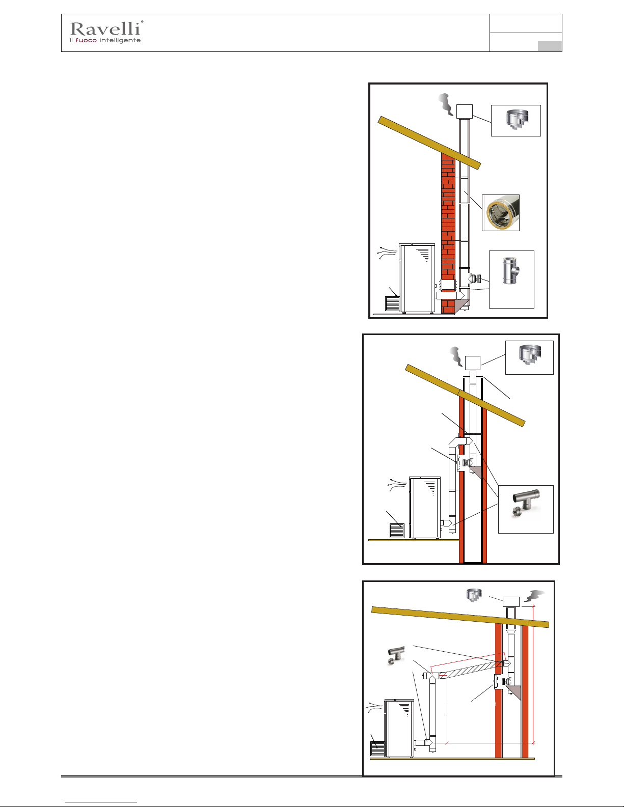
Manuel d’utilisation et d’entretien Vela 7-9
Page 91
Rév.1 20.02.18
FR
Ce type d’installation (voir la Fig. 4) exige une sortie de toit isolée
car l’ensemble du conduit de fumée a été monté à l’extérieur de
l’habitation.
Un raccord de type en « T » doté d’un bouchon d’inspection a été
monté dans la partie inférieure de la sortie de toit.
Fig.4
Protection de la pluie
Conduit d’évacuation des
fumées isolé
Raccord en T avec
évacuation de la
condensation et
chambre de
récupération
SORTIE DE TOIT INTERNE
Fig.5
Protection de la pluie
Plaque de recouvrement
Lamiera in acciaio a tenuta stagna
Raccord en T avec
chambre de récupération et pour la
condensation
Botola d’ispezione
Ce type d’installation (voir la Fig. 5) n’exige pas de sortie de toit
isolée car une partie du conduit de fumée a été montée à l’intérieur
de l’habitation et une partie se trouve à l’intérieur d’une sortie de
toit déjà existante.
Un raccord de type en « T » doté d’un bouchon d’inspection a été
monté dans la partie inférieure du chaudière ainsi qu’à l’intérieur
de la sortie de toit.
Comme premier tronçon initial, il est interdit d’installer un coude
à 90°, car la cendre bloquerait le passage des fumées en peu de
temps, en causant des problèmes de tirage du chaudière.(Voir la
Fig.2)
Ce type d’installation (voir la Fig.6) requiert un tronçon horizontal
pour se raccorder à une sortie de toit déjà existante.
Respecter les pentes indiquées sur la gure de manière à réduire
le dépôt des cendres dans le tronçon du tuyau horizontal. Un
raccord de type en « T » doté d’un bouchon d’inspection a été
monté dans la partie inférieure et à l’entrée de la sortie de toit.
Comme tronçon initial, il est interdit d’installer un coude à 90°, car
la cendre bloquerait le passage des fumées en peu de temps, en
causant des problèmes de tirage du chaudière. (Voir la Fig. 2)
2 - 3 mt
max
Hauteur supérieure à 4 m
Pente 3 - 5 %
Max 2 -3 mt
SORTIE DE TOIT INTERNE
Fig.6
Raccord en T pour la
condensation
Protection de la pluie
Prise d’air à
l’extérieur
Prise d’air à
l’extérieur
Prise
d’air à
l’extérieur
Trappe d’inspection
Trappe d’inspection

Manuel d’utilisation et d’entretien Vela 7-9
Page 92
Rév.1 20.02.18
FR
Raccordements
! IMPORTANT
Les raccordements doivent être effectués par un technicien qualié et / ou autorisé par
le Fabricant.
Connexion avec prise d’air externe
Le poêle a été conçu pour des installations hermétiques.
Pour établir la connexion avec une prise d’air extérieure, procédez comme suit:
étape action
1
Connecter un tuyau de 50 mm de diamètre au tuyau d’entrée d’air de combustion à l’arrière du poêle.
Remarque: le tuyau ne doit pas mesurer plus de 2 m de longueur.
La prise d’air doit être installée de manière à ne pas pouvoir être bloquée.
Raccordement à la sortie de toit
La sortie de toit doit être dimensionnée de manière à assurer le tirage déclaré par le Fabricant.
Connexion électrique
La prise du câble d’alimentation du poêle doit être connectée uniquement après l’installation et le montage.
de l’appareil, et doit rester accessible après l’installation.
Pour effectuer la connexion électrique, procédez comme suit:
étape action
1 Branchez le cordon d’alimentation à l’arrière du poêle.
2 Connectez la fiche du cordon d’alimentation à la prise murale.
Schema elettrico KTR AIR (congurazione ventilata o canalizzata singola)
Vers. 03 del 22/03/16
!
"!!
!#
!"
!
$%
!
"
&!
$%
!'
!
&
&!
!'
$
%"!
%"!
M2
M3
S1
R1
S2
G1
nero
rosso
bianco
Schema elettrico Scheda madre
RETE ALIMENTAZIONE 220 V
S3
G4
G5
G2
Scheda OPZIONALE
per gestione
domotica
N
COM
NC
NO
G6
G2
NCG6NOG6C
G6
G5 G5
10 9 8 7 6 5 4 3 2 1
Connessione OPZIONALE per
gestione domotica
Neutro
M4
M5
Fase
M1
bianco
verde
T1
T5
T3
T2
T4
Carte optionelle
pour gestion
domotique
LEGENDE
Sécurités
T1 – Sécurité pellet
T2 – Vacuostat
T2 - Blocage nettoyeur
Moteurs
M1 – Motoréducteur vis
d’Archimède
M2 – Echangeur
M3 – Extracteur fumées
M4 – Nettoyeur automatique
M5 – Compacteur + turbulateurs
M6 – Valve 2 voies Chauff/Sani
Résistance
R1 Résistance
Sondes
S1 – Sonde H20 ret. Sonde
Puffer L
S2 – Sonde amme (K)
S3 – Therm externe /Sonde env.
S4 – Sonde chauffe-eau
S5 – Sonde H20 refoulement
S6 – Sonde Puffer H
Générique
G1 – Pressostat
G2 – Débitmètre
G1 – Pressostat
G4 – Compte coups nettoyeur
automatique
G5 –Encoder lecture tours
extracteur
G6 – Ordinateur de poche
“RADIO” Touch
G7 – Contact DOMOTIQUE
G8 – Contact allumage GAZ –
Indication alarme sortie
domotique (TRF 58)

Manuel d’utilisation et d’entretien Vela 7-9
Page 93
Rév.1 20.02.18
FR
Schéma électrique
Test d’essai et mise en service
La mise en service doit être précédée d'un test qui prévoit la vérication du fonctionnement des éléments suivants:
• raccordement au système d'évacuation des fumées ;
• vérication que tous les matériaux pour la construction du conduit de fumée, de la sortie de toit et du terminal de cheminée soient
conformes et appropriés à l'utilisation.
Le test d’essai n’est réussi que lorsque toutes les phases de fonctionnement s’achèvent sans relever d’anomalies.
Commandes et utilisation
Description du portable:
Le portable se présente comme dans l’image suivante:
Les informations ci-dessous vous permettra de vous familiariser avec le produit et obtenir les meilleures performances.
Insertion des batteries dans le portable:
Retirez le couvercle de protection de la batterie à l’arrière de la télécommande comme indiqué dans la gure A , et entrez n. 3 piles
(1,5 V type AAA ) dans l’emplacement de votre ordinateur en faisant attention à la polarité. Replacez le couvercle de protection piles
Manuale utente PALMARE IDRO TOUCH RADIO Manuale utente PALMARE IDRO TOUCH RADIO
Pag.22 Pag.23
Vers. 01 del 07/04/15 Vers. 01 del 07/04/15
Raccord électrique
Branchez le cordon d’ alimentation à l’arrière du poêle d’abord, puis à une prise de courant sur le mur.
Le commutateur de la gure I/O doit être réglé sur I pour alimenter la chaudière. En cas de panne
de courant pour contrôler l’état du fusible placé dans le tiroir sous l’interrupteur ( fusible 4A). Lorsqu’il
n’est pas utilisé, il est conseillé d’enlever le cordon d’alimentation de la chaudière.
Opérations préliminaires
Vériez que vous avez extrait et retiré de la chambre de combustion ou de la vitre tous les composants qui pourraient brûler (diver-
ses étiquettes adhésives ou des instructions).
Avant d’allumer l’appareil, vérier le positionnement correct du brasier sur sa base et que la porte et le tiroir à cendres soient bien
fermés.
Ce qu’il faut vérier avant d’allumer le poêle
Le chargement des pastilles de combustible se fait par l’insertion, la partie supérieure de la chaudière par l’ouverture de la porte.
chargement évitez que le sac de granulés entre en contact avec des surfaces chaudes.
Charge de pellet
NE PAS INTRODUIRE UN AUTRE TYPE DE CARBURANT DANS LE RÉSERVOIR AUTRE QUE DU PELLET
CONFORME AUX SPECIFICATIONS INDIQUES PRECEDEMMENT.
Le portable se présente comme dans l’image suivante:
Description du portable:
1
Touche d'augmentation "EN HAUT" (touche de
sélection)
2
Touche de diminution "EN BAS" (touche de
sélection)
3
Touche ON/OFF ou retablicement de la
modalité “Sleep“
4
Display
5
Touche pou acceder au MENU e sortie
6
Touche de conrmation
1
2
5
6
4
3
Dans “Sleep” écran du portable est
obscurci, tout en maintenant une
communication radio active avec l’ap-
pareil de chauffage, an de réduire la
consommation de la batterie.
Initialisation du portable
Pour être en mesure de fonctionner correctement , l’ordinateur de poche nécessite une interface avec la carte électronique à l’in-
térieur du poêle Pour cette raison , l’écran afche le message suivant:
Dans le cas de la première utilisation de votre appareil, sélectionnez OUI avec les touches de sélection et conrmer avec la touche
Entrée.
L’afchage de poche afchera l’écran suivant:
Maintenez enfoncé pendant quelques secondes le bouton de communication radio ( RADIO ADJ ) de la carte électronique, situées
à l’arrière du poêle, pour initialiser l’appareil.
Le voyant jaune clignotant indique que la carte de circuit est en attente de recevoir le signal de l’ordinateur de poche.
En appuyant sur la touche Entrée du portable, les composants entrent en communication les uns avec les autres. Un signal coché
sur le display e un signal acustiqueinduìique que l’aoperation de initialisation du palmaire a eté fait avec success.
Dans “Sleep” écran du portable est
obscurci, tout en maintenant une
communication radio active avec
l’appareil de chauffage, an de réduire
la consommation de la batterie.
Manuale utente PALMARE IDRO TOUCH RADIO Manuale utente PALMARE IDRO TOUCH RADIO
Pag.22 Pag.23
Vers. 01 del 07/04/15 Vers. 01 del 07/04/15
Raccord électrique
Branchez le cordon d’ alimentation à l’arrière du poêle d’abord, puis à une prise de courant sur le mur.
Le commutateur de la gure I/O doit être réglé sur I pour alimenter la chaudière. En cas de panne
de courant pour contrôler l’état du fusible placé dans le tiroir sous l’interrupteur ( fusible 4A). Lorsqu’il
n’est pas utilisé, il est conseillé d’enlever le cordon d’alimentation de la chaudière.
Opérations préliminaires
Vériez que vous avez extrait et retiré de la chambre de combustion ou de la vitre tous les composants qui pourraient brûler (diver-
ses étiquettes adhésives ou des instructions).
Avant d’allumer l’appareil, vérier le positionnement correct du brasier sur sa base et que la porte et le tiroir à cendres soient bien
fermés.
Ce qu’il faut vérier avant d’allumer le poêle
Le chargement des pastilles de combustible se fait par l’insertion, la partie supérieure de la chaudière par l’ouverture de la porte.
chargement évitez que le sac de granulés entre en contact avec des surfaces chaudes.
Charge de pellet
NE PAS INTRODUIRE UN AUTRE TYPE DE CARBURANT DANS LE RÉSERVOIR AUTRE QUE DU PELLET
CONFORME AUX SPECIFICATIONS INDIQUES PRECEDEMMENT.
Le portable se présente comme dans l’image suivante:
Description du portable:
Les informations ci-dessous vous permettra de vous familiariser avec le produit et obtenir les meilleures performances.
Insertion des batteries dans le portable:
Retirez le couvercle de protection de la batterie à l’arrière de la télécommande comme indiqué dans la gure A , et entrez n. 3 piles
(1,5 V type AAA ) dans l’emplacement de votre ordinateur en faisant attention à la polarité. Replacez le couvercle de protection
piles comme dans la gure B
1
Touche d'augmentation "EN HAUT" (touche de
sélection)
2
Touche de diminution "EN BAS" (touche de
sélection)
3
Touche ON/OFF ou retablicement de la
modalité “Sleep“
4
Display
5
Touche pou acceder au MENU e sortie
6
Touche de conrmation
1
2
5
6
4
3
Figura A
Figura B
Dans “Sleep” écran du portable est
obscurci, tout en maintenant une
communication radio active avec l’ap-
pareil de chauffage, an de réduire la
consommation de la batterie.
Dans le cas de remplacement de batteries il n’est pas nécessaire d’ effectuer la procédure d’initialisation du portable. Dans
ce cas , lorsque l’écran afche le message “ AVANT D’INSTALLER ? “ , Sélectionnez Non et appuyez sur la touche Entrée.
Initialisation du portable
Pour être en mesure de fonctionner correctement , l’ordinateur de poche nécessite une interface avec la carte électronique à l’in-
térieur du poêle Pour cette raison , l’écran afche le message suivant:
Dans le cas de la première utilisation de votre appareil, sélectionnez OUI avec les touches de sélection et conrmer avec la touche
Entrée.
L’afchage de poche afchera l’écran suivant:
Maintenez enfoncé pendant quelques secondes le bouton de communication radio ( RADIO ADJ ) de la carte électronique, situées
à l’arrière du poêle, pour initialiser l’appareil.
Le voyant jaune clignotant indique que la carte de circuit est en attente de recevoir le signal de l’ordinateur de poche.
En appuyant sur la touche Entrée du portable, les composants entrent en communication les uns avec les autres. Un signal coché
sur le display e un signal acustiqueinduìique que l’aoperation de initialisation du palmaire a eté fait avec success.
Description du display
Le display du portable se présente comme de suite (conditions de stand-by):
comme dans la gure B PROCÉDURES D’UTILISATION
Manuale utente PALMARE IDRO TOUCH RADIO Manuale utente PALMARE IDRO TOUCH RADIO
Pag.22 Pag.23
Vers. 01 del 07/04/15 Vers. 01 del 07/04/15
Raccord électrique
Branchez le cordon d’ alimentation à l’arrière du poêle d’abord, puis à une prise de courant sur le mur.
Le commutateur de la gure I/O doit être réglé sur I pour alimenter la chaudière. En cas de panne
de courant pour contrôler l’état du fusible placé dans le tiroir sous l’interrupteur ( fusible 4A). Lorsqu’il
n’est pas utilisé, il est conseillé d’enlever le cordon d’alimentation de la chaudière.
Opérations préliminaires
Vériez que vous avez extrait et retiré de la chambre de combustion ou de la vitre tous les composants qui pourraient brûler (diver-
ses étiquettes adhésives ou des instructions).
Avant d’allumer l’appareil, vérier le positionnement correct du brasier sur sa base et que la porte et le tiroir à cendres soient bien
fermés.
Ce qu’il faut vérier avant d’allumer le poêle
Le chargement des pastilles de combustible se fait par l’insertion, la partie supérieure de la chaudière par l’ouverture de la porte.
chargement évitez que le sac de granulés entre en contact avec des surfaces chaudes.
Charge de pellet
NE PAS INTRODUIRE UN AUTRE TYPE DE CARBURANT DANS LE RÉSERVOIR AUTRE QUE DU PELLET
CONFORME AUX SPECIFICATIONS INDIQUES PRECEDEMMENT.
Le portable se présente comme dans l’image suivante:
Description du portable:
Les informations ci-dessous vous permettra de vous familiariser avec le produit et obtenir les meilleures performances.
Insertion des batteries dans le portable:
Retirez le couvercle de protection de la batterie à l’arrière de la télécommande comme indiqué dans la gure A , et entrez n. 3 piles
(1,5 V type AAA ) dans l’emplacement de votre ordinateur en faisant attention à la polarité. Replacez le couvercle de protection
piles comme dans la gure B
Le portable, après un premier court écran montrant le logo Ravelli, il donnera la liste des langues disponibles dans le menu
1
Touche d'augmentation "EN HAUT" (touche de
sélection)
2
Touche de diminution "EN BAS" (touche de
sélection)
3
Touche ON/OFF ou retablicement de la
modalité “Sleep“
4
Display
5
Touche pou acceder au MENU e sortie
6
Touche de conrmation
1
2
5
6
4
3
Figura A
Figura B
Dans “Sleep” écran du portable est
obscurci, tout en maintenant une
communication radio active avec l’ap-
pareil de chauffage, an de réduire la
consommation de la batterie.
Dans le cas de remplacement de batteries il n’est pas nécessaire d’ effectuer la procédure d’initialisation du portable. Dans
ce cas , lorsque l’écran afche le message “ AVANT D’INSTALLER ? “ , Sélectionnez Non et appuyez sur la touche Entrée.
Initialisation du portable
Pour être en mesure de fonctionner correctement , l’ordinateur de poche nécessite une interface avec la carte électronique à l’in-
térieur du poêle Pour cette raison , l’écran afche le message suivant:
Dans le cas de la première utilisation de votre appareil, sélectionnez OUI avec les touches de sélection et conrmer avec la touche
Entrée.
L’afchage de poche afchera l’écran suivant:
Maintenez enfoncé pendant quelques secondes le bouton de communication radio ( RADIO ADJ ) de la carte électronique, situées
à l’arrière du poêle, pour initialiser l’appareil.
Le voyant jaune clignotant indique que la carte de circuit est en attente de recevoir le signal de l’ordinateur de poche.
En appuyant sur la touche Entrée du portable, les composants entrent en communication les uns avec les autres. Un signal coché
sur le display e un signal acustiqueinduìique que l’aoperation de initialisation du palmaire a eté fait avec success.
Description du display
Le display du portable se présente comme de suite (conditions de stand-by):
Après 5 minutes d’inactivité, le display du portable va s’obscurcir en modalité “SLEEP”, tout en maintenant la connexion
radio avec le poêle.
Le portable, après un premier court écran montrant le logo Ravelli, il donnera la liste des langues disponibles dans le menu
Selectioner la langue avec les touches 1 et 2 et valider la selection avec la touche de conrmation
Initialisation du portable
Pour être en mesure de fonctionner correctement , l’ordinateur de poche nécessite une interface avec la carte électronique à l’intérieur
PREMIERE INSTALLATION
OUI

Manuel d’utilisation et d’entretien Vela 7-9
Page 94
Rév.1 20.02.18
FR
du poêle Pour cette raison , l’écran afche le message suivant:
Dans le cas de la première utilisation de votre appareil, sélectionnez OUI avec les touches de sélection et conrmer avec la touche
Entrée.
PREMIERE INSTALLATION
OUI
APPUYER TOUCHE
RADIO ADJ SUR LE POELE
L’afchage de poche afchera l’écran suivant:
Maintenez enfoncé pendant quelques secondes le bouton de communication radio ( RADIO ADJ ) de la carte électronique, situées
4
32
1 5
1
2
3
4
5
Prise en série
Prise de branchement du câble de l’ordinateur de poche
Radio ADJ : bouton pour raccorder l’ordinateur de poche à la
carte
DEL de signalisation
Rouge : alarme activée
Jaune : En attente de communication avec l’ordinateur de
poche
Vert : Cuisinière allumée
Touche d’allumage/d’extinction de la cuisinière
à l’arrière du poêle, pour initialiser l’appareil.
Le voyant jaune clignotant indique que la carte de circuit est en attente de recevoir le signal de l’ordinateur de poche.
En appuyant sur la touche Entrée du portable, les composants entrent en communication les uns avec les autres. Un signal coché
Dans le cas de remplacement de batteries il n’est pas nécessaire d’ effectuer la procédure d’initialisation du portable. Dans
ce cas , lorsque l’écran afche le message “ AVANT D’INSTALLER ? “ , Sélectionnez Non et appuyez sur la touche Entrée.
Initialisation du portable
Pour être en mesure de fonctionner correctement , l’ordinateur de poche nécessite une interface avec la carte électronique à l’in-
térieur du poêle Pour cette raison , l’écran afche le message suivant:
Dans le cas de la première utilisation de votre appareil, sélectionnez OUI avec les touches de sélection et conrmer avec la touche
Entrée.
L’afchage de poche afchera l’écran suivant:
Maintenez enfoncé pendant quelques secondes le bouton de communication radio ( RADIO ADJ ) de la carte électronique, situées
à l’arrière du poêle, pour initialiser l’appareil.
Le voyant jaune clignotant indique que la carte de circuit est en attente de recevoir le signal de l’ordinateur de poche.
En appuyant sur la touche Entrée du portable, les composants entrent en communication les uns avec les autres. Un signal coché
sur le display e un signal acustiqueinduìique que l’aoperation de initialisation du palmaire a eté fait avec success.
PREMIERE INSTALLATION
OUI
APPUYER TOUCHE
RADIO ADJ SUR LE POELE
sur le display e un signal acustiqueinduìique que l’aoperation de initialisation du palmaire a eté fait avec success.
Description du display
Dans le cas de remplacement de batteries il n’est pas nécessaire d’ effectuer la procédure d’initialisation du portable. Dans
ce cas , lorsque l’écran afche le message “ AVANT D’INSTALLER ? “ , Sélectionnez Non et appuyez sur la touche Entrée.
Initialisation du portable
Pour être en mesure de fonctionner correctement , l’ordinateur de poche nécessite une interface avec la carte électronique à l’in-
térieur du poêle Pour cette raison , l’écran afche le message suivant:
Dans le cas de la première utilisation de votre appareil, sélectionnez OUI avec les touches de sélection et conrmer avec la touche
Entrée.
L’afchage de poche afchera l’écran suivant:
Maintenez enfoncé pendant quelques secondes le bouton de communication radio ( RADIO ADJ ) de la carte électronique, situées
à l’arrière du poêle, pour initialiser l’appareil.
Le voyant jaune clignotant indique que la carte de circuit est en attente de recevoir le signal de l’ordinateur de poche.
En appuyant sur la touche Entrée du portable, les composants entrent en communication les uns avec les autres. Un signal coché
sur le display e un signal acustiqueinduìique que l’aoperation de initialisation du palmaire a eté fait avec success.
Description du display
Le display du portable se présente comme de suite (conditions de stand-by):
2
3
1
Après 5 minutes d’inactivité, le display du portable va s’obscurcir en modalité “SLEEP”, tout en maintenant la connexion
radio avec le poêle.
La première pression sur n’importe quelle touche avec le display actif allume son rétro-éclairage, en le considérant pas
comme un commande.
PREMIERE INSTALLATION
OUI
APPUYER TOUCHE
RADIO ADJ SUR LE POELE
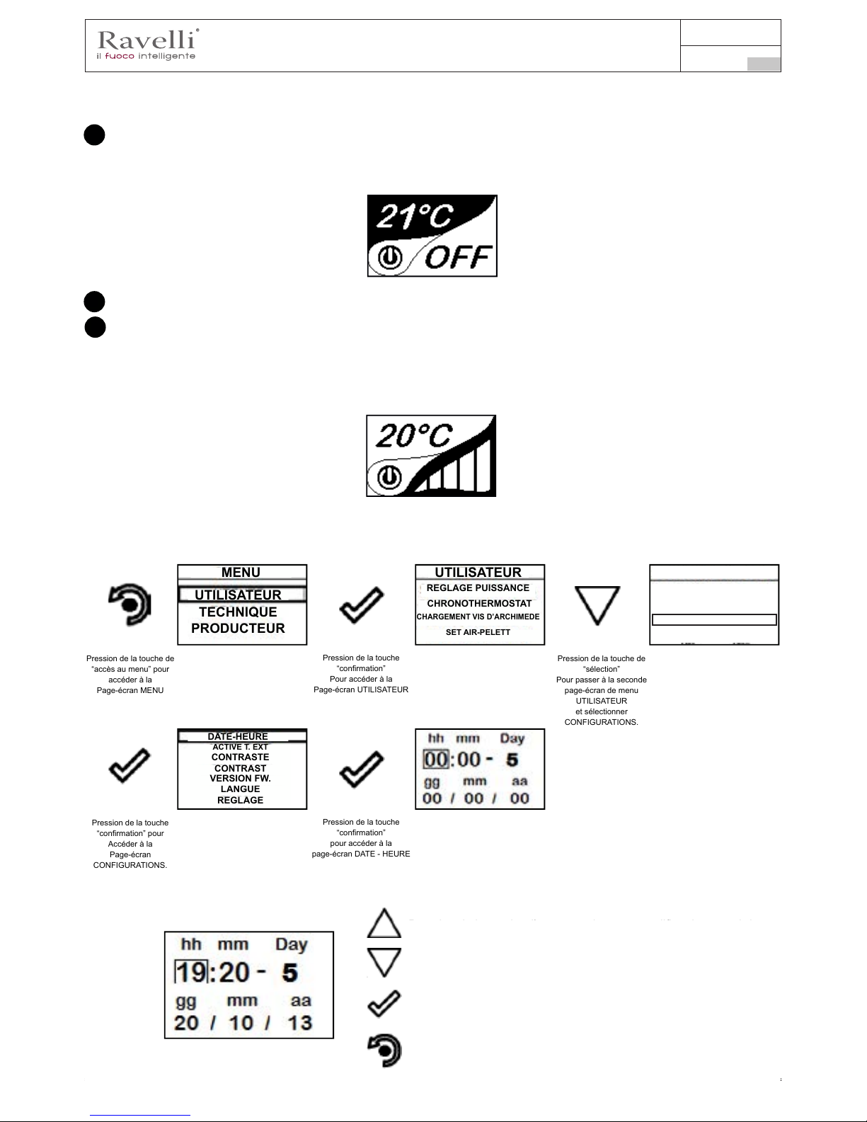
Manuel d’utilisation et d’entretien Vela 7-9
Page 95
Rév.1 20.02.18
FR
Le display du portable se présente comme de suite (conditions de stand-by):
Le display se divise en trois parties
Afche la température ambiance actuelle détectée par le portable. En outre, la pression de la touche de délement HAUT
vous permet d’afcher la température de réglage, modiable avec les deux touches de délement HAUT/ BAS’ . La conrmation de
chaque variation a lieu automatiquement dans les 3 secondes après la modication effectuée ou par la pression de la touche de
conrmation.
1
Pag.24 Pag.25
Vers. 01 del 07/04/15 Vers. 01 del 07/04/15
Conguration de la date et de l’heure
Ci-après sont reportées les opérations à suivre pour accéder au menu relatif.
Pression de la touche de
“accès au menu” pour
accéder à la
Page-écran MENU
Pression de la touche
“conrmation”
Pour accéder à la
Page-écran UTILISATEUR
MENU UTILISATEUR
REGLAGE PUISSANCE
CHRONOTHERMOSTAT
CHARGEMENT VIS D’ARCHIMEDE
UTILISATEUR
TECHNIQUE
PRODUCTEUR
Un signal acoustique conrme le changement s’est produit.
Image qui indique l’état du poele(voir schéma sjnthetique phases
Dans les premiers stades inactifs (en liaison avec la partie 2 du display) indique l’état du poêle.
Dans les phases actives indique la puissance de travail du poêle.
En plus, en appuyant sur la touche de délement BAS vous pouvets voir la puissance reglée, modiable
avec les deux touches de délement HAUT/BAS: La conrmation de tout changement s’effectue automatiquement dans les 3
secondes après la modication ou par la pression de la touche de conrmation.Un signal acoustique conrme le changement s’est
produit.
2
3
Pag.24 Pag.25
Vers. 01 del 07/04/15 Vers. 01 del 07/04/15
Conguration de la date et de l’heure
Ci-après sont reportées les opérations à suivre pour accéder au menu relatif.
Pression de la touche de
“accès au menu” pour
accéder à la
Page-écran MENU
Pression de la touche
“conrmation”
Pour accéder à la
Page-écran UTILISATEUR
Pression de la touche
“conrmation” pour
Accéder à la
Page-écran
CONFIGURATIONS.
Pression de la touche
“conrmation”
pour accéder à la
page-écran DATE - HEURE
MENU UTILISATEUR
REGLAGE PUISSANCE
CHRONOTHERMOSTAT
CHARGEMENT VIS D’ARCHIMEDE
UTILISATEUR
TECHNIQUE
PRODUCTEUR
ACTIVE T. EXT
CONTRASTE
CONTRAST
LANGUE
REGLAGE
VERSION FW.
DATE-HEURE
Configuration de la date et de l’heure
Ci-après sont reportées les opérations à suivre pour accéder au menu relatif.
Pression de la touche d’augmentation pour modier chaque rubrique
Pression de la touche d’augmentation pour modier chaque rubrique
Pression de la touche “confìrmation” pour conrmer le réglage et
passer à la rubrique successive.
Pression répétée de la touche “retour” pour visualiser la page-écran
de stand-by.
Pression de la touche de
“accès au menu” pour
accéder à la
Page-écran MENU
Pression de la touche
“conrmation”
Pour accéder à la
Page-écran UTILISATEUR
Pression de la touche de
“sélection”
Pour passer à la seconde
page-écran de menu
UTILISATEUR
et sélectionner
CONFIGURATIONS.
Pression de la touche
“conrmation” pour
Accéder à la
Page-écran
CONFIGURATIONS.
Pression de la touche
“conrmation”
pour accéder à la
page-écran DATE - HEURE
MENU UTILISATEUR
SELECTION PUISSANCE
REGLAGE PUISSANCE
CHRONOTHERMOSTAT
CHARGEMENT VIS D’ARCHIMEDE
SET AIR-PELETT
UTILISATEUR
TECHNIQUE
PRODUCTEUR
ACTIVE T. EXT
CONTRASTE
CONTRAST
LANGUE
REGLAGE
VERSION FW.
DATE-HEURE
UTILISATEUR
CONFORT CLIMA
PROGRAMMATION
Pression de la touche d’augmentation pour chaque voix.
Pression de la touche de diminution pour chaque voix.
Pression de la touche ‘‘entrée’’ pour conrmer le règlage et passer
à la position succesive.
Pression répéTéE DE LA TOUCHE ‘‘retoucr’’ pour afcher le mode
stand- by.

Manuel d’utilisation et d’entretien Vela 7-9
Page 96
Rév.1 20.02.18
FR
PROCÉDURES D’UTILISATION
En cas d’incendie de la sortie de toit, appeler immédiatement les Sapeurs Pompiers.
Vérications avant l’allumage
Le contenu de ce manuel d’instructions ait été lu et parfaitement bien compris ;
Avant d’allumer le poêle, il faut veiller à ce que :
• la chambre de combustion soit propre ;
• tous les éléments susceptibles de brûler (manuel d’instructions, étiquettes adhésives diverses) aient été éliminés.
! IMPORTANT
Pendant les premières heures d’utilisation, il se peut que les peintures utilisées pour la
nition du poêle dégagent une odeur désagréable. Il se peut que vous sentiez aussi l’odeur
typique des pièces métalliques soumises aux températures élevées. Veiller à ce qu’un
renouvèlement d’air sufsant soit garanti dans la pièce. Inévitables, ces désagréments
vont disparaître après les premières heures de fonctionnement. Pour minimiser ces
désagréments, laisser le poêle allumé quelques heures à basse puissance et au début, ne
pas surcharger en évitant les cycles lourds de chauffage-refroidissement.
! IMPORTANT
Pendant l’allumage initial, la peinture termine son séchage et se durcit. Ainsi, pour ne pas
les endommager, il est déconseillé de toucher les surfaces peintes du poêle.
Remplir le combustible
Utilisez uniquement des granulés de bois, les caractéristiques indiquées dans ce manuel.
Le chargement des granulés doit avoir lieu lorsque le poêle est éteint. Si le poêle est allumé, l’opération doit être
terminée dans un délai d’une minute, sinon le poêle s’éteindra.
Pendant la phase de chargement, empêchez le sac de granulés de toucher les surfaces chaudes.
Allumer et éteindre l’appareil
A partir de l’écran “stand-by”, il est possible d’allumer et d’éteindre le poêle en maintenant le bouton ON / OFF enfoncé sur l’appareil
pendant quelques secondes. Un signal acoustique vous avertira que l’appareil est allumé ou éteint. Au cas où ce n’est pas possible
En utilisant votre ordinateur de poche, vous pouvez allumer / éteindre l’appareil en utilisant le bouton approprié sur la carte électronique.
! IMPORTANT
Le brasero est nettoyé mécaniquement avant chaque allumage, sauf après l’alimentation
de la vis initiale et en cas de ré-allumage après une alarme FAILED IGNITION
N’éteignez pas le chauffage en débranchant la fiche de la prise murale.
Que faire en cas d’alarme “Ignition”
Pour rallumer le poêle, réinitialisez l’alarme en appuyant sur le bouton d’alimentation de l’ordinateur de poche (ou sur la carte
électronique) jusqu’à ce que le signal acoustique soit entendu, puis rallumez-le.
Il n’est pas nécessaire d’enlever les pellets non brûlés à l’intérieur du brasier. En effet, dès que l’utilisateur redémarre le poêle, le
système essaie d’allumer tout le carburant restant dans le brasier avant de commencer la phase de chargement.

Manuel d’utilisation et d’entretien Vela 7-9
Page 97
Rév.1 20.02.18
FR
Allumage de l’appareil
Maintenir la pression sur la touche ON/OFF pendant quelques secondes pour allumer le poêle.
L’apparition du message “REGLER SYSTEME RDS” indique que la procédure d’essai et réglage des paramètres Initial
n’est pas effectuée correctement. Cette indication n’implique pas le blocage du poêle (voir section POP UP D’INDICATION).
L’afcheur illustrera la page-écran suivante:
Une pression prolongée de la touche ON/OFF provoque l’extinction du poêle, ansi que le reset d’éventuelles alarmes. Dans le cas
où les opérations de chargement de la vis d’Archimède décrites ci-avant n’aient pas été exécutées, cela pourrait donner lieu à des
épisodes de non allumage du poêle. Vider le brasier et remettre à zero l’alarme et répéter l’allumage. Au cas où se produiraient des
non-allumages répétés, contrôler que le brasier soit logé et en parfait contact avec la base d’appuii; Verier en outre que ne soient
pas présentes d’inscrustations qui empêchent le passage correct d’air pour permettre l’allumage.
Si le problème persiste, contacter le service d’assistance.
Pour les modèles avec nettoyeur automatique, pendant la phase d’allumage, le poêle active une phase de nettoyage du
brasier avant de passer à l’ALLUMAGE. En cas de NON ALLUMAGE il n’est pas nécessaire d’enlever le pellet non brûlé
À l’intérieur du brasier avant d’effectuer un nouvel allumage. Dès que l’utilisateur rallume le poêle, le système de
fonctionnement exécute l’opération sans activer le nettoyeur et sans démarrer à nouveau la phase de chargement.
Séquence des phases d’allumage
ALLUMAGE – phase initiale de
chargement pellet;
ATTENTE FLAMME – phase
d’attentedéveloppement de la ame;
PHASE FLAMME – phase de
stabilisation amme et réduction
comburant à l’intérieur du brasier
TRAVAIL – phase de fonctionnement
Décrite dans le chapitre dédié;
En case de batterie déchargée à
l’intérieur de la “goutte” est présent un
symbole Qui indique l’état de limite de
celle-ci, tout en maintentant actives les
fonctions de l’ordinateur de poche.
Dès que le niveau de batterie
ne permet en aucune sorte la
communication radio, l’ordinateur de
poche afche plein écran entier l’image
de la batterie déchargée, en bloquant
toute les fonctions de l’ordinateur
portable jusqu’à l’effective substitution
des batteries.
Chargement de la vis sans n
Avant d’effectuer le premier allumage du poêle, à chaque fois que le poêle est en état d’alarme « 06 - Granulés épuisés » et, en règle
générale, à chaque fois que la trémie est complètement vide, il faut effectuer le chargement initial de la vis sans n. Cette phase
sert à remplir le système de chargement des granulés de bois pour qu’au moment de l’allumage, le système soit prêt à charger les
granulés dans le brasier.
Si les opérations de chargement de la vis sans n ne sont pas effectuées, il se peut qu’il ait des épisodes de défaut d’allumage du
poêle.
Au cas où l’on voudrait relever la temperature ambiante au moyen d’un thermostat externe (option), celui-ci devra être
raccordé au connecteur spécialement placé sur la partie arrière du poêle; on devra par consequent activer la lecture
Dans le menu spécial “CONFIGURATIONS – HABILITATION THERMOSTAT”. Sur l’afcheur apparaitra l’inscription TON
/ TOFF sur la base de la demande du thermostat.
RACCORDER UN THERMOSTAT EXTERNE QUI AIT SIMPLEMENT UN CONTACT PROPRE, PAR CONSEQUENT
NON EN TENSION. EN OUTRE UN THERMOSTAT EST CONSEILLE AVEC OFFSET D’AU MOINS 3°C SI ON VEUT
UTILISER LA FONCTION CONFORT CLIMA.
MENU
UTILISATEUR
TECHNIQUE
PRODUCTEUR
UTILISATEUR
UTILISATEUR
REGLAGE PUISSANCE
ETAT POELE
CHRONOTHERMOSTAT
CONFORT CLIMA.
CHARGEMENT VIS D’ARCHIMEDE
CONFIGURATIONS
SET AIR-PELETT
Pression de la touche «
accès aux menus » pour
accéder à la page MENU
Pression de la touche
« confirmer » pour
accéder à la page
UTILISATEUR
Pression de la touche «
confirmer » pour activer
la rotation de la vis sans
fin.
LE TEMPS DU CHARGEMENT INITIAL PRÉ-CONFIGURÉ EST TEL QU'IL INCLUT ÉGALEMENT ASSEZ DE GRANULÉS
DE BOIS POUR EFFECTUER LE PREMIER ALLUMAGE. APRÈS LE CHARGEMENT INITIAL, AUCUN NETTOYAGE DU
BRASIER NE PRÉCÈDERA DONC LA PHASE D’ALLUMAGE.

Manuel d’utilisation et d’entretien Vela 7-9
Page 98
Rév.1 20.02.18
FR
Phases de fonctionnement de l’appareil
La modulation
Pendant la phase de travail, le but de l’appareil est celui d’atteindre le réglage de la température ambiante/eau chaudière demandée
par l’utilisateur, quand cette condition est remplie, le poêle passe en modalité MODULE, phase pendant laquelle la consommation
de combustible est minimum.
Au cas où l’on voudrait relever la temperature ambiante au moyen d’un thermostat externe (option), celui-ci devra
être raccordé au connecteur spécialement placé sur la partie arrière du poêle; on devra par consequent activer
la lecture. Dans le menu spécial “CONFIGURATIONS – HABILITATION THERMOSTAT”. Sur l’afcheur apparaitra
l’inscription TON/ TOFF sur la base de la demande du thermostat.
RACCORDER UN THERMOSTAT EXTERNE QUI AIT SIMPLEMENT UN CONTACT PROPRE, PAR CONSEQUENT NON
EN TENSION. EN OUTRE UN THERMOSTAT EST CONSEILLE AVEC OFFSET D’AU MOINS 3°C SI ON VEUT UTILISER
LA FONCTION CONFORT CLIMA.
Confort clima
L’activation de cette fonction permet au poêle, une fois atteinte la température ambiante/eau chaudière voulue, de réduire le
chargement de pellet en activant la phase de modulation. Successivement le poêle vérie que la température soit maintenue pendant
une période de temps établi, et si cela se produit, il passe automatiquement en extinction, en montrant sur l’afcheur l’inscription
ECO.Le poêle se rallume quand la température descend en-dessous d’un seuil conguré.
Ci-après sont reportées les opérations à suivre pour accéder au menu relatif.
Au cas où l’on voudrait relever la temperature ambiante au moyen d’un thermostat externe (option), celui-ci devra être
raccordé au connecteur spécialement placé sur la partie arrière du poêle; on devra par consequent activer la lecture
Dans le menu spécial “CONFIGURATIONS – HABILITATION THERMOSTAT”. Sur l’afcheur apparaitra l’inscription TON
/ TOFF sur la base de la demande du thermostat.
RACCORDER UN THERMOSTAT EXTERNE QUI AIT SIMPLEMENT UN CONTACT PROPRE, PAR CONSEQUENT
NON EN TENSION. EN OUTRE UN THERMOSTAT EST CONSEILLE AVEC OFFSET D’AU MOINS 3°C SI ON VEUT
UTILISER LA FONCTION CONFORT CLIMA.
Pression de la touche de
“accès au menu” pour
accéder à la
page-écran MENU
Pression de la touche
“conrmation”
pour accéder à la
page-écran UTILISATEUR
Pression de la touche de
“sélection”
pour passer à la seconde
page-écran de menu UTILISATEUR
et sélectionner
CONFORT CLIMA.
MENU
UTILISATEUR
TECHNIQUE
PRODUCTEUR
UTILISATEUR
UTILISATEUR
REGLAGE PUISSANCE
ETAT POELE
CHRONOTHERMOSTAT
CONFORT CLIMA.
CHARGEMENT VIS D’ARCHIMEDE
CONFIGURATIONS
SET AIR-PELETT
CHARGEMENT VIS SANS FIN
CHRONOTHERMOSTAT
SET AIRE-GRANULES
ETAT POELE
Au cas où l’on voudrait relever la temperature ambiante au moyen d’un thermostat externe (option), celui-ci devra être
raccordé au connecteur spécialement placé sur la partie arrière du poêle; on devra par consequent activer la lecture
Dans le menu spécial “CONFIGURATIONS – HABILITATION THERMOSTAT”. Sur l’afcheur apparaitra l’inscription TON
/ TOFF sur la base de la demande du thermostat.
RACCORDER UN THERMOSTAT EXTERNE QUI AIT SIMPLEMENT UN CONTACT PROPRE, PAR CONSEQUENT
NON EN TENSION. EN OUTRE UN THERMOSTAT EST CONSEILLE AVEC OFFSET D’AU MOINS 3°C SI ON VEUT
UTILISER LA FONCTION CONFORT CLIMA.
Pression de la touche de
“accès au menu” pour
accéder à la
page-écran MENU
Pression de la touche
“conrmation”
pour accéder à la
page-écran UTILISATEUR
Pression de la touche de
“sélection”
pour passer à la seconde
page-écran de menu UTILISATEUR
et sélectionner
CONFORT CLIMA.
MENU
UTILISATEUR
TECHNIQUE
PRODUCTEUR
UTILISATEUR
UTILISATEUR
REGLAGE PUISSANCE
ETAT POELE
CHRONOTHERMOSTAT
CONFORT CLIMA.
CONFORT CLIMA.
CHARGEMENT VIS D’ARCHIMEDE
CONFIGURATIONS
SET AIR-PELETT
ACTIVATION CONFORT
ACTIVATION CONFORT ACTIVATION CONFORT
GESTION CONFORT
DELTA REDEMARRAGE
RETARD EXTINCTION
Au cas où l’on voudrait relever la temperature ambiante au moyen d’un thermostat externe (option), celui-ci devra être
raccordé au connecteur spécialement placé sur la partie arrière du poêle; on devra par consequent activer la lecture
Dans le menu spécial “CONFIGURATIONS – HABILITATION THERMOSTAT”. Sur l’afcheur apparaitra l’inscription TON
/ TOFF sur la base de la demande du thermostat.
RACCORDER UN THERMOSTAT EXTERNE QUI AIT SIMPLEMENT UN CONTACT PROPRE, PAR CONSEQUENT
NON EN TENSION. EN OUTRE UN THERMOSTAT EST CONSEILLE AVEC OFFSET D’AU MOINS 3°C SI ON VEUT
UTILISER LA FONCTION CONFORT CLIMA.
Pression de la touche de
“accès au menu” pour
accéder à la
page-écran MENU
Pression de la touche
“conrmation”
pour accéder à la
page-écran UTILISATEUR
Pression de la touche de
“sélection”
pour passer à la seconde
page-écran de menu UTILISATEUR
et sélectionner
CONFORT CLIMA.
Sélectionner le type de gestion
Confort Clima sur la t°C
Eau ou sur la température
ambiante au moyen de la touche
èche EN HAUT ou èche EN
BAS
Touche “V” pour conrmer la
“sélection”
MENU
UTILISATEUR
TECHNIQUE
PRODUCTEUR
UTILISATEUR
UTILISATEUR
REGLAGE PUISSANCE
ETAT POELE
CHRONOTHERMOSTAT
CONFORT CLIMA.
CONFORT CLIMA.
CONFORT CLIMA.
AIR
EAU
DELTA CONFORT
CLIMA
DELTA CONFORT
CLIMA
RETARD
EXTINCTION
RETARD
EXTINCTION
CONFORT CLIMA.
CONFORT CLIMA.
CHARGEMENT VIS D’ARCHIMEDE
CONFIGURATIONS
SET AIR-PELETT
ACTIVATION CONFORT
ACTIVATION CONFORT
ACTIVATION CONFORT
ACTIVATION CONFORT
ACTIVATION CONFORT ACTIVATION CONFORT
GESTION CONFORT
GESTION CONFORT
GESTION CONFORT
GESTION CONFORT
DELTA REDEMARRAGE
DELTA REDEMARRAGE
DELTA REDEMARRAGE
DELTA REDEMARRAGE
RETARD EXTINCTION
RETARD EXTINCTION
RETARD EXTINCTION
RETARD EXTINCTION
Appuyer à plusieurs reprises la touche jusqu’au retour de l’écran de Stand-by
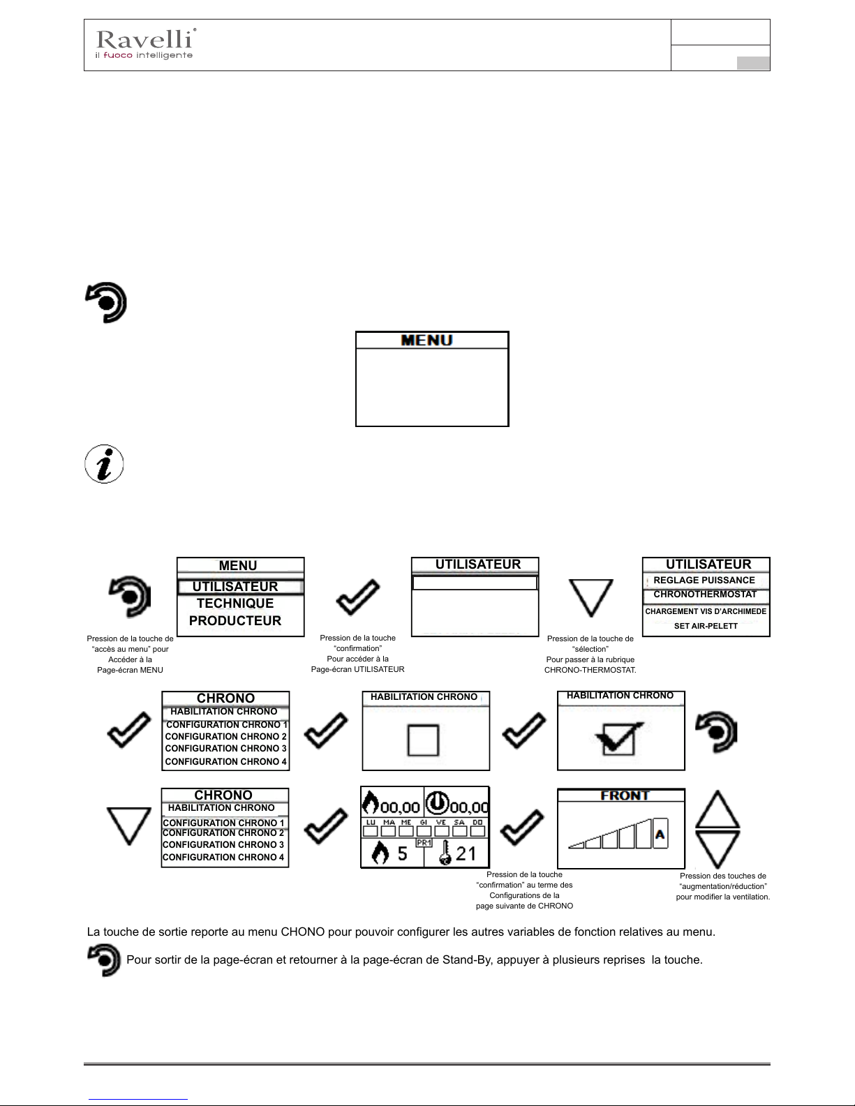
Manuel d’utilisation et d’entretien Vela 7-9
Page 99
Rév.1 20.02.18
FR
La première conguration permet l’activation de la fonction CONFORT CLIMA; cette fonction a le but de vérier que la température
congurée à l’environnement /eau chaudière soit maintenue au réglage imposé pour une période maximum de “X” minutes (RETARD
EXTINCTION : 5 MIN) avant de passer à la phase d’ECO STOP. Le poêle maintient cet état jusqu’à ce que la température de
l’environnement / eau chaudière descend en-dessous de la valeur congurée (DELTA CONFORT CLIMA: 5°C).
La fonction GESTION CONFORT permet le choix d’activer l’extinction du poêle quand le réglage est atteint environnement AIR plutôt
que celui de l’eau chaudière EAU (au choix de l’utilisateur).
Par exemple, avec un set ambiant de 21°C, le poêle s’éteint quand elle est atteinte, pour repartir quand est détectée une température
de 16°C (21°C - 5°C).
Il est possible d’activer la fonction également en utilisant un thermostat externe, en tenant en compte que celui ne contemple la valeur
d’hystérisis.
Description des fonctions au menu
Pression de la touche pour accéder à la page-écran des MENUS
UTILISATEUR
TECHNIQUE
PRODUCTEUR
Les menus TECHNICIEN et PRODUCTEUR sont protégés par password d’accès
Chrono-thermostat
Avec la fonction Chrono-thermostat il est possible de programmer pour chaque jour de la semaine l’allumage et l’extinction automatique
du poêle en 4 intervalles temporaires indépendants (CONFIGURATION CHRONO 1-2-3-4) Ci-après sont reportées les opérations
à suivre pour accéder au menu relatif.
Manuale utente PALMARE IDRO TOUCH RADIO Manuale utente PALMARE IDRO TOUCH RADIO
Pag.32 Pag.33
Vers. 01 del 07/04/15 Vers. 01 del 07/04/15
Pression de la touche
“conrmation” pour
Accéder à la
Page-écran
CONFIGURATIONS.
Pression de la touche de
“sélection” pour passer à la
à la rubrique
VERSION FW.
Pression de la touche
“conrmation”
pour accéder à la fonction
Pour accéder à la conguration suivante, suivre les mêmes étapes reportées précédemment ou plus simplement enlever et remettre
les batteries, l’ordinateur de poche se remet à zero et demande à nouveau la langue que l’on veut congurer.
Congurations > Langue
Congurations > Adjust
A l’aide des touches “EN HAUT” et “EN BAS” il est
possible de modier une variation à la valeur nette de la
sonde ambiante présente à l’intérieur de l’ordinateur de
poche par rapport à une valeur de référence. La valeur
peut varier de -10°C à 10°C.La valeur standard est 0°C.
La pression de la touche suivante permet la conrmation
de la donnée et le passage à la page-écran à l’intérieur
du menu CONFIGURATIONS.
Menu VENTILATION (fonction présente uniquement pour les modèles où est reportée la note sur le manuel dédié)
Gestion : la ventilation peut être congurée de 0 à AUTO où 0 indique la désactivation de celle-ci, la conguration de MIN à MAX
Permet le choix de la vitesse de propagation de la chaleur Si conguré la valeur AUTO, la ventilation suit la puissance
congurée du poêle.
Pour sortir de la page-écran et retourner à la page-écran de Stand-By, appuyer à plusieurs reprises la touche.
La touche de sortie reporte au menu CHONO pour pouvoir congurer les autres variables de fonction relatives au menu.
La température lue au moyen de l’ordinateur de poche gère la modulation du poêle. Si on veut moduler la ventilation avec
la modulation du poêle, congurer le ventilateur en modalité A comme illustré dans le chapitre.
Pression de la touche de
“accès au menu” pour
Accéder à la
Page-écran MENU
Pression de la touche
“conrmation”
Pour accéder à la
Page-écran UTILISATEUR
Pression de la touche de
“conrmation”
Pour passer à la rubrique
VENTILATION.
Pression des touches de
“augmentation/réduction”
pour modier la ventilation.
Page-écrans visualisées avec l’activation de schémas évolués
En activant un schéma installation différent de celui standard (schéma 0), tout en maintenant les mêmes fonctions au menu, la page-écran
de “Stand-by” on adapte la visualisation de tous les appareils raccordés comme par exemple la température du chauffe-eau et du puffer. Ci-
après est reporté pour chaque schéma la nouvelle visualisation et la spécication pour modier les divers réglages.
Schéma 1 (gestion chauffe-eau ACS + chauffage)
Le schéma suivant peut être utilisé quand on possède un poêle sans échangeur à plaques et on désire acheter un accumulateur
(chauffe-eau) à raccorder au circuit an de produire de l’eau sanitaire.
Dans ce type de circuit la gestion de la température ambiante est gérée dans tous les cas par l’ordinateur de poche qui, étant radio,
sert de chrono-thermostat à distance. Le chauffe-eau est géré par le poêle grâce à une sonde à contact ou à immersion (non de série)
à raccorder sur le côté arrière du poêle. Ci-après est reporté le nouvel état de “Stand-by”.
En congurant la fonction ETE, la valve à trois voies reste xe dans une unique position, en permettant la cession de la
chaleur produite par la chaudière, uniquement à l’intérieur du chauffe-eau. Dès que cette condition est remplie, la chaudière
entre en modalité ECO STOP.
Le fonctionnement est le même que le schéma base, avec l’unique différence que dans ce schéma la chaudière échange directement
dans le chauffe-eau (priorité); quand est atteint le set température conguré, la valve à trois voies change de position et la chaudière
commence à Échanger dans le circuit de chauffage. A partir de ce moment le poêle est géré par l’ordinateur de poche radio pour la
gestion ambiante o dal settaggio H2O (voir fonctionnement relatif au schéma 0 en ce qui concerne la modulation, eco stop, etc.).Ou
par le réglage H2O (voir fonctionnement relatif au schéma 0 en ce qui concerne modulation, eco stop, etc.).
La valve à trois voies se dirige à nouveau dans le chauffe-eau quand :
- demandée de la part du chauffe-eau ;
- demandée par le uxostat (option si raccordé).
D’un état de Eco-stop ou Stand by, la chaudière repart en considérant les demandes du chauffage ou du chauffe-eau.
Fonction chrono
En activant la fonction chrono, il est possible pour chaque programmation de gérer la vitesse de la ventilation comme spéciée ci-
dessus la logique.
Pression de la touche de
“accès au menu” pour
Accéder à la
Page-écran MENU
Pression de la touche
“conrmation”
Pour accéder à la
Page-écran UTILISATEUR
Pression de la touche de
“sélection”
Pour passer à la rubrique
CHRONO-THERMOSTAT.
Si le type de schéma installation projeté, nécessite la gestion de la valve à trois voies (schéma 1 et 3) il s’avère nécessaire
d’acheter le kit optionnel auprès du propre revendeur ou centre Ravelli autorisé.
DATE-HEURE
DATE-HEURE
HABILITATION T. EXT
HABILITATION T. EXT
SAISON
SAISON
CONTRASTE
CONTRASTE
VERSION FW
VERSION FW
LANGUE
LANGUE
REGLAGE
REGLAGE
REGLAGE
MENU
UTILISATEUR
TECHNIQUE
PRODUCTEUR
PUISS. VENTILATION
UTILISATEUR
VENTILATION
REGLAGE PUISSANCE
CHRONOTHERMOSTAT
CHARGEMENT VIS D’ARCHIMEDE
MENU
UTILISATEUR
TECHNIQUE
PRODUCTEUR
UTILISATEUR UTILISATEUR
REGLAGE PUISSANCE REGLAGE PUISSANCE
SET AIR-PELETT
SET AIR-PELETT
CHRONOTHERMOSTAT
CHRONOTHERMOSTAT
CHARGEMENT VIS D’ARCHIMEDE
CHARGEMENT VIS D’ARCHIMEDE
CHARGEMENT VIS SANS FIN
CHRONOTHERMOSTAT
SET AIRE-GRANULES
ETAT POELE
Pression des touches de
“augmentation/réduction”
pour modier la ventilation.
Pour sortir de la page-écran et retourner à la page-écran de Stand-By, appuyer à plusieurs reprises la touche.
La touche de sortie reporte au menu CHONO pour pouvoir congurer les autres variables de fonction relatives au menu.
Pression de la touche
“conrmation” au terme des
Congurations de la
page suivante de CHRONO
CHRONO
CHRONO
HABILITATION CHRONO
HABILITATION CHRONO
HABILITATION CHRONO
HABILITATION CHRONO
PUISS. VENTILATION
CONFIGURATION CHRONO 1
CONFIGURATION CHRONO 1
CONFIGURATION CHRONO 2
CONFIGURATION CHRONO 2
CONFIGURATION CHRONO 3
CONFIGURATION CHRONO 3
CONFIGURATION CHRONO 4
CONFIGURATION CHRONO 4

Manuel d’utilisation et d’entretien Vela 7-9
Page 100
Rév.1 20.02.18
FR
Etat poêle
Ci-après sont reportées les opérations à suivre pour accéder au menu relatif.
Manuale utente PALMARE IDRO TOUCH RADIO Manuale utente PALMARE IDRO TOUCH RADIO
Pag.30 Pag.31
Vers. 01 del 07/04/15 Vers. 01 del 07/04/15
Ci-après sont reportées les opérations à suivre pour accéder au menu relatif.
Etat poêle
Pression de la touche de
“accès au menu” pour
accéder à la
page-écran MENU
Pression de la touche
“conrmation”
pour accéder à la
page-écran UTILISATEUR
Pression de la touche de
“sélection”
pour passer à la rubrique
ETAT Poêle.
Congurations > Habilitation thermostat
Pression de la touche “conrmation”
pour accéder à la page-écran
CONFIGURATIONS.
MENU
UTILISATEUR
TECHNIQUE
PRODUCTEUR
UTILISATEUR
UTILISATEUR
REGLAGE PUISSANCE
ETAT POELE
CHRONOTHERMOSTAT
CONFORT CLIMA.
CHARGEMENT VIS D’ARCHIMEDE
CONFIGURATIONS
SET AIR-PELETT
CHARGEMENT VIS SANS FIN
CHRONOTHERMOSTAT
SET AIRE-GRANULES
ETAT POELE
RPM
T
Tsk
g/min
°C
°C
ALARME
ACTIVE
- Tours extracteurs
- Temperature;
- Temperature che électronique;
- Etat poêle
Pour sortir de l’écran ETAT POELE et revenir en Stand-by, appuyez sur la touche à plusieurs reprises.
Réglages > Activez le thermostat
Voici les étapes à suivre, à partir de l’ècran de veille, pour accéder au menu relatif.Dans ce menu, vous pouvez vérier le bon
Manuale utente PALMARE IDRO TOUCH RADIO Manuale utente PALMARE IDRO TOUCH RADIO
Pag.30 Pag.31
Vers. 01 del 07/04/15 Vers. 01 del 07/04/15
Pression de la touche de
“accès au menu” pour
accéder à la
page-écran MENU
Pression de la touche
“conrmation”
pour accéder à la
page-écran UTILISATEUR
Pression de la touche de
“sélection”
pour passer à la rubrique
ETAT Poêle.
Congurations > Habilitation thermostat
Pression de la touche “conrmation”
pour accéder à la page-écran
CONFIGURATIONS.
MENU
UTILISATEUR
TECHNIQUE
PRODUCTEUR
UTILISATEUR
UTILISATEUR
REGLAGE PUISSANCE
ETAT POELE
CHRONOTHERMOSTAT
CONFORT CLIMA.
CHARGEMENT VIS D’ARCHIMEDE
CONFIGURATIONS
SET AIR-PELETT
CHARGEMENT VIS SANS FIN
CHRONOTHERMOSTAT
SET AIRE-GRANULES
ETAT POELE
CONFORT CLIMA
PROGRAMMATION
chargement vis sans n
chargement vis sans n
PROGRAMMATION
Congurations > Habilitation thermostat
Pression de la touche “conrmation”
pour accéder à la page-écran
CONFIGURATIONS.
Pression de la touche de
“sélection” pour passer à la rubrique
HABILITATION THERMOSTAT.
Pression de la touche
“conrmation”
pour accéder à la fonction
Pression de la touche
“conrmation”
pour habiliter la fonction
En état de Stand-By, à la place de la température ambiante
Détectée et congurable apparait la chaine T ON si la pièce
dans laquelle il est installé le thermostat n’a pas encore
atteint la température demandée, ou l’inscription T OFF Si
dans la pièce la température ambiante est atteinte.
Pression répétée de la
touche pour retourner à la
page-écran de
“STAND-BY”
DATE-HEURE
DATE-HEURE
ACTIVATION THERMOSTAT
ACTIVATION THERMOSTAT
HABILITATION T. EXT
HABILITATION T. EXT
SAISON
SAISON
CONTRASTE
CONTRASTE
VERSION FW
VERSION FW
LANGUE
LANGUE
REGLAGE
REGLAGE
PROGRAMMATION
Dans ce menu, vous pouvez vérier le bon fonctionnement des paramètres les plus importants de l’appareil. Ce qui suit est une liste
de vraies données de poêle utiles pour le service d’assistance pendant les phases de contrôle.
 Loading...