

RAVAK RC1-L1, RC1-L2 Assembly Manual, Putting Device To Operation And Operating Instructions
Page 1

RAVAK LIVING 1
CZ
GB
D
PL
HU
RU
SK
CZ
GB
D
PL
HU
RU
SK
Návod k montáži, uvedení do provozu a návod k použití
Assembly Manual, Putting Device to Operation and Operating Instructions
Montageanleitung, Inbetriebnahme und Gebrauchsanweisung
Instrukcja monta¿u i u¿ycia, uruchomienie urz¹dzenia
Szerelési, üzembe helyezési és használati utasítás
Návod na montáž, uvedenie do prevádzky a návod na použitie
Руководствопоустановке,вводувэксплуатацию
и руководство по использованию
Page 2

CZ
RAVAK LIVING 1 - Návod k montáži
a uvedení do provozu
Tento návod popisuje jakmontovat, zapojit a uvést do provozu systém RAVAK LIVING 1.
Dùležité
Nebezpeèí úrazu elektrickým proudem
Nakládání s pøístroji pøi likvidaci
strana 3
Postup montáže
Výmìna vadné žárovky
Možné závady a jejich odstranìní
Použité symboly:
Obsah:
Bezpeènostní pokyny
Montáž a elektrické pøipojení
Uvedení systému do provozu
Údržba a servis
strana 3
strana 4
strana 4
Výmìna baterií v dálkovém ovladaèi
strana 5
strana 5
strana 6
strana 7
strana 7
strana 8
strana 8
strana 9
strana 10
Záruka
Nakládání s obalovým materiálem a s výrobkem po skonèení životnosti
Návod k použití
Obrázek 1: Klávesnice
Obrázek 2: Umístìní svìtel
Základní schéma
Schéma zapojení
Základní technické parametry
Rozmìrové nákresy
Tento návodpeèlivì uschovejte!
Umístìní svìtel a krytky ventilátoru
Umístìní dálkového ovládaèe a reproduktoru
!
!
-2-
Page 3

Bezpeènostní pokyny
Montáž a elektrické pøipojení
- Napájecí zdroj je zkonstruován v souladu s požadavky na spotøebiè tøídy 1 a musí být podle toho
zapojen.
- Všechny prvky systému musí být kryty nehoølavým, odvìtrávaným podhledem. Prvky nad úrovní
podhledu nesmí být vystaveny kapající èi støíkající vodì. Z pohledové strany je odolnost proti vodì
urèena stupnìm krytí (IP xx) daného prvku.
- Baterie použité v dálkovém ovladaèi nesmìjí být vystaveny nadmìrnému teplu, napø. sluneènímu
záøení, ohni a podobnì.
- Z dùvodù údržby a pøípadného servisu zaøízení musí být umožnìno odpojení systému od napájení. Pro
tento úèel lze použít samostatný dvojpólový odpojovací prvek pøípadnì proudový chrániè kombinovaný
s jistièem splòující požadavek na dvojpólové odpojení.
Je doporuèeno, aby reproduktor s IR senzorem byl v pøímé viditelnosti
s dálkovým ovladaèem,ale ne vždy to stavební situaceumožòuje. Bezproblémového pøenosu øídících IR
signálù lze èasto dosáhnout i pøirozenými odrazy bez pøímé viditelnosti. Je však nutné pøed definitivní
montáží prvkù ovìøit plnou funkènost systému.
- V zadní èásti dálkového ovladaèe jsou vestavìny dva silné magnety, jejichž pomocí se ovladaè pøichytí
ke kovovému štítku. Kovový štítek lze pøišroubovat ke stìnì, pøípadnì pøipevnit oboustrannou lepící
páskou k dlaždièkám a pod. Pøi osazení více štítkù je možné pøemisťovat ovladaè na nìkolik míst.
Ovladaè je také možné pøilepit oboustrannou lepící páskou pøímo. Tento zpùsob øešení pøináší však
komplikace pøi výmìnì baterií.
Napájení systému je možné zapnout až po úplném pøipojení a dokonèení montáže, jinak hrozí
nebezpeèí úrazu elektrickým proudem.
- Výrobek smí být používán pouze pro úèely popsané dále.
- Pøi instalaci a provozu musí být dodrženy všechny pøíslušné platné normy a pøedpisy.
- Montáž a uvedení do provozu smí provádìt pouze osoba s pøíslušnou elektrotechnickou kvalifikací.
Pøed vrtáním do stìn èi stropu se pøesvìdète, že pod povrchem nejsou rozvody elektøiny, plynu
nebo vody.
- Øídící jednotka a napájecí zdroj se upevòují na strop nad podhledem, pøípadnì na nosnou konstrukci
podhledu. Vhodné umístìní volte s ohledem na pøístupnost pro montáž a kontrolu, nejlépe v místech
odnímatelného podhledu.
- Øídící jednotka má vyveden kabel délky 1,5 m urèený k propojení s napájecím zdrojem. Dále jsou
z øídící jednotky vyvedeny 2 kabely délky 2,0 m pro pøipojeníreproduktorù a kabel antény délky2,5 m.
- Pro rozmístìní jednotlivých dílù se doporuèuje pøedem zpracovat jednoduchý projekt nebo grafický
návrh, který slouží souèasnì pro rozpis materiálu a nákup dílù.
- Centrální svìtlo se umisťuje do støedu stropu, blíže k zrcadlu. Pokud ve vanì budete èíst, je vhodné
smìrovat bodová svìtla do tohoto prostoru. Mohou být smìrována také na umyvadlo nebo na další
místa, která chceme v koupelnì zdùraznit, kupø. relief na obkladu a pod.
- Krytku ventilátoru je vhodné umístit poblíž stabilnì zabudovaného ventilátoru nebo vìtracího otvoru.
- Prvky se osazují do otvorù v podhledu 140 x 140 mm, kde jsouupevnìny pružinou.
- Z pohledové strany kryje výøez v podhledu rámeèek. Pro montáž a kontrolu jsou svìtla i ostatní díly
vyjímatelné z vnìjší strany podhledu.
- Pro umístìní ovládání pøedem vyberte nejvhodnìjší místo, které Vám i ostatním uživatelùm bude
nejlépe vyhovovat. V koupelnì je nejlepší umístìní na stìnì nad vanou dosažitelné z ležící polohy.
Z dùvodu úklidu koupelny by však mìlo být minimálnì 15 cm nad okrajem vany. Na WC se ovladaè
umisťuje v dosahu sedící osoby.
- Podle projektované vybavenosti rozmìøte na stropním podhledu místa osazení jednotlivých svìtel,
reproduktorù a dalších doplòkù.
- Vyøíznìte do podhleduotvory 140 x 140 mm.
- Do mezistropního prostoru osaïte øídící jednotku a napájecí zdroj.
Umístìní svìtel a krytky ventilátoru:
Umístìní dálkového ovládaèe a reproduktoru:
Postup montáže:
-3-
Page 4

- Kabel z øídící jednotky s konektorem pøipojte na reproduktor. Øídící jednotka je pøipravena pro volitelné
pøipojení pøídavného reproduktoru. Pokud jej nevyužijete, nezapojené konektory musí být zajištìny proti
vzájemnému dotyku a dotyku s kovovými pøedmìty. Pokud se rozhodnete pro pøipojení druhého reproduktoru, musí být oba reproduktory zapojeny barevnì shodnì (hnìdý vodiè na “+” kontakt reproduktoru
a bílý vodiè na druhý kontakt reproduktoru).
- Pøipojte centrální svìtlo na svìtelný pøívod. Pokud používáte stávající instalaci, bude nutné pøívod
dostateènì prodloužit.
- Po pøipojení svìtla,reproduktoru èi jiného doplòku podržteupínací pera na rámeèku a zasuòte výrobek
do otvoru v podhledu. Tahem za rámeèek lze výrobek demontovat.
- Odšroubujte víko napájecího zdroje a pøipojte podle schema pøívodní kabely s dostateènou rezervou
délky.
- V pøípadì, že to místní situace a platné normy vyžadují, proveïte pospojení s ochrannými vodièi
a všemi pøedmìty specifikovanými normou. K pospojení použijte mechanicky chránìný mìdìný vodiè
o prùøezu 2,5 mm se žlutozelenouizolací.
- Všechny propojovací kabely musí mít kulatý prùøez pro dodržení dostateèného krytí. Nepoužité
vývodky musí být osazeny náhradní ucpávkou. Všechny kabelové vývodky napájecího zdroje musí být
øádnì dotaženy z dùvodù mechanického zajištìní kabelù a dodržení udávaného krytí.
- Po kontrole zapojení a zajištìní krytù pøipojte systém na síť, pøekontrolujte všechny funkce v plném
rozsahu podle návodu k obsluze. Polohou øídící jednotky a vhodným smìrováním antény lze ovlivnit
kvalitu pøíjmu rádia.
- Definitivnì upevnìte dálkový ovladaè.
Montážní organizace potvrdí záruèní list a pøedá uživateli montážní návod i návod k obsluze.
Seznámí uživatele s funkcí a obsluhou systému.
Zaøízení nevyžaduje zvláštní údržbu. K èištìní nesmí být používány abrasivní prostøedky (napø. brusné
pasty a pod.) ani agresivní chemikálie (obsahující rozpouštìdla, kyseliny a louhy). V prostoru, ve kterém
je zaøízení namontováno, není dovoleno používat èistící prostøedky, jejichž výpary pùsobí agresivnì na
kovové èásti (napø.kyselina chlorovodíková). Bìžnáúdržba se provádí pouze otíráním dílùa skel vlhkým
hadøíkem pøi vypnutém systému. K odstranìní starých, zašlých neèistot doporuèujeme použít èistící
prostøedek RAVAK CLEANER.
Pokud signalizaèní LED (v obrázku è.1 oznaèená èíslem 8) na ovladaèi pøi stisku tlaèítka nebliká, nebo
zaøízení nereaguje na stisky tlaèítek dálkového ovladaèe, je tøeba vymìnit baterie. K výmìnì použijte
šroubovák a dvì nové baterie velikosti “AAA”. Doporuèujeme použít kvalitní alkalické baterie,
u kterých je jistota, že nedoje k zneèištìní a poškození kontaktù držáku a elektroniky dálkového
ovladaèe. Po sejmutí ovladaèe povolte dva šrouby na zadní stìnì, odejmìte víèko a vymìòte baterie.
Zkontrolujte neporušenost a správné umístìní tìsnìní pod víèkem. Po opìtovném zakrytí bateriového
prostoru víèkem pøimìøenì dotáhnìte oba šroubky a odzkoušejte funkènost.
Do vnitøku dálkového ovladaèe se v žádném pøípadì nesmí dostat voda ani vlhkost. Pokud pøes
všechna opatøení dojde ke vniku vlhkosti, vyjmìte baterie a nezakrytovaný ovladaè nechte
dùkladnì vyschnout (na mírnì teplém suchém místì, napø. nad radiátorem ústøedního topení).
Zajistìte vypnutí celého systému a vyèkejde zchladnutí vadné žárovky. Opatrným tahem za plíšek
smìrem od okraje svìtla uvolnìte sklo a po jeho mírném vyklopení jej vyjmìte. Demontáž vadné
žárovky proveïte zmáèknutím keramického držáku na jedné stranì a souèasnì tlaèením žárovky do
protilehlého držáku. Novou žárovku stejného typu a výkonu doporuèeného v návodu namontujte
opaèným postupem. Žárovky se nesmíte dotýkat prsty a v pøípadì, že by k tomu pøesto došlo, oèistìte ji
odmašťovacím prostøedkem. Novou žárovku mírnì vyosenou oproti koneènému umístìní tlaète do
jednoho držáku za souèasného zmáèknutí druhého držáku. Potom žárovku srovnejte do osy držákù
a uvolnìte síly roztahující držáky od sebe. Na závìr montujte ochranné sklo. Tlakem na plíšek
zamáèknìte mírnì naklonìné sklo do jedné strany rámeèku, srovnejte do roviny a po uvolnìní tlaku sklo
o cca 2 mm zajede i na stranì plíšku do otvoruv rámeèku.
2
Uvedení systému do provozu
Údržba a servis.
Výmìna baterií v dálkovém ovladaèi:
Výmìna vadné žárovky v centrálním svìtle:
!
-4-
Page 5

Výmìna vadné žárovky v bodovém svìtle:
Zajistìte vypnutí celého systému a vyèkejde zchladnutí vadné žárovky. Uvolnìním pružné drátové
pojistky pod žárovkou umožníte vysunutí žárovky dolù. Mírným pootoèením bajonetové objímky
vadnou žárovku uvolnìte. Místo ní do objímky umístìte a otoèením zajistìte novou žárovku, typu
a výkonu doporuèeného v návodu. Žárovku vsuòte do držáku a zajistìte drátovou pojistkou.
LIVING 1 je elektrické zaøízení a v pøípadì neodborné manipulace hrozí nebezpeèí úrazu elektrickým
proudem a vznik hmotných škod. Opravu svìøte pracovníkovi s odbornou zpùsobilostí k tìmto pracem.
Pokud systém nefunguje, je nutné zkontrolovat:
- zda nejsou vybité baterie v dálkovém ovladaèi.
- zda je zaøízení napájeno elektrickou energií.
- zda jsou v poøádku obì pojistky v napájecím zdroji (pojistky mohou být nahrazeny pouze stejným typem
a hodnotou).
Pokud systém reaguje, ale svìtlo nesvítí, je potøeba zkontrolovat a pøípadnì vymìnit žárovku.
Nepodaøí-li se nalézt a odstranit závadu, kontaktujte prosím prodejce, nebo pøímo servisní støedisko
našeho výrobního závodu.
oškození peèeti na øídící
jednotce, pøípadnì pøi zásahu do výrobku nelze záruku uplatnit.
e www.ravak.cz, www.ravak.com nebo na telefonní lince844 844
874.
Možné závady a jejich odstranìní.
Záruka:
Na výrobek je dle platné legislativy poskytována záruka v délce 24 mìsícù od dne pøevzetí zboží
kupujícím, uvedeného v záruèním listì jako datum prodeje, nebo datum instalace výrobku. Záruka je
platná pouze v pøípadì øádnì vyplnìného záruèního listu. Zákazník je povinen uplatnit záruku
u prodávajícího, uvedeného v záruèním listu. Bìh záruèní doby se prodlužuje o dobu, po kterou byl
výrobek v reklamaèním øízení a reklamace byla uznána za oprávnìnou.
Práva z odpovìdnosti za vadu vìci, pro které platí záruèní podmínky, zaniknou, nebyla-li uplatnìna
v záruèní lhùtì. Výrobce neuznává žádný požadavek náhrady škody za pøípadnou škodu zpùsobenou
kupujícím nebo tøetí osobou z dùvodu nedodržení stavební pøipravenosti a veškerých pokynù výrobce
v návodu na obsluhu, instalaci a údržbì výrobku a ostatních dokumentech.
Záruka se vztahuje na veškeré užitné funkce, vlastnosti výrobku, jeho vzhled a kvalitu povrchu.
Záruka se nevztahuje na závady vzniklé neodbornou instalací, závady vzniklé používáním v rozporu
s návodem na obsluhu a na závady vzniklé nesprávným ošetøením, údržbou výrobku a použitím
nevhodných èisticích prostøedkù. Dále se záruka nevztahujena opotøebení výrobkunad rámec bìžného
užívání, mechanické nebo jiné poškození výrobku, na poškození zpùsobené použitím nevhodných
baterií a na použití výrobku v nesprávných nebo extrémních podmínkách. Pøi p
Výrobce si vyhrazuje právo prùbìžné inovace výrobku. Veškeré podrobné informace ohlednì výrobku
získáte u svého prodejce nebo naadres
Nakládání s obalovým materiálem a s výrobkem po skonèení životnosti
Informace pro uživatele k likvidaci elektrických a elektronických zaøízení
Využitelné složky obalu, napø. karton, lepenku nebo PE folii použijte sami nebo nabídnìte k dalšímu
využití èi recyklaci. Nevyužitelné složky obalù a výrobku po skonèení životnosti je nutné zneškodnit
bezpeèným zpùsobem dle platného zákona o odpadech.
Uvedený symbol na výrobku nebo v prùvodní dokumentaci znamená, že použité elektrické nebo
elektronické výrobky nesmí být likvidovány spoleènìs komunálním odpadem. Za úèelem správné
likvidace výrobku jej odevzdejte na urèených sbìrných místech.
Pro správnou likvidaci elektrických a elektronických zaøízení si vyžádejte podrobné informace
u Vašehoprodejce nebo dodavatele.
-5-
!
Page 6

Dálkovì ovládané zaøízení LIVING 1 umožòuje pøíjem FM rádia, spínání dvou svìtelných okruhù
a èasování ventilátoru. Skládá se z napájecího zdroje, øídící jednotky, reproduktoru s infradetektorem
a dálkového ovladaèe. Volitelnì lze dokoupit pøídavný reproduktor, externì spínané centrální svìtlo,
bodová svìtla, dálkový ovladaè proovládání druhého svìtelného okruhu, pøípadnìkrytku ventilátoru.
Ovládání systému LIVING 1 (èíslovanépoložky odpovídají oznaèení tlaèítek na obrázku è.1).
1. Svìtlo ON/OFF zapnuto / vypnuto
2. Ventilátor ON/OFF zapnuto / vypnuto
3. Rádio ON/OFF zapnuto / vypnuto
4. a 5. Regulace hlasitosti Volume -, Volume +(vol.)
6. a 7. Prohledávání frekvenèníhopásma Tuner (tun.)
8. Indikaèní LED.
Autonomní vypnutí systému
Centrální svìtlo
Sestava LIVING 1 umožòuje ovládat dva svìtelné okruhy. Dálkové ovládání RC1-L1 øídí svìtelný
okruh “A”, dálkové ovládání RC2-L1 øídí svìtelný okruh “B”. Krátkým stiskem tlaèítka è.1 se pøíslušný
svìtelný okruh rozsvítí, opìtovným stiskem tlaèítka è.1 se okruh vypne. Podržením tlaèítka po dobu
jedné vteøiny lze vypnout obasvìtelné okruhy souèasnì.
První stisk tlaèítka è.2 zapíná ventilátor a nastaví èasované vypnutí na 5 minut. Druhý stisk
prodlouží interval provozu na 10 minut, tøetí stisk na 15 minut. Ètvrtý stisk tlaèítka è.2 pøedèasnì ukonèí
èasování a ventilátor vypíná.
Stiskem tlaèítka è.3 se rádio zapne na poslední zvolené (naladìné) stanici. Dalším stiskem tlaèítka
è.3 se rádiovypne. Pøi vypnutí rádia senaladìná frekvence ahlasitost rádia uloží do pamìti. Obsahpamìti
je uchován i pøi výpadkunapájecího napìtí.
Hlasitost lze plynule regulovat od minimální (ztlumeno) do maximální hodnoty. Tlaèítko (+) è.4
zvyšuje hlasitost od nastavené hodnoty do maxima, tlaèítko (-) è.5 snižuje hlasitost k minimu. Krátký stisk
tlaèítka sníží (-) nebo zvýší (+) hlasitost o jeden stupeò. Držením tlaèítka lze plynule snižovat / zvyšovat
hlasitost až k požadované hodnotì.
Zapnutý pøijímaè lze pøeladit na jinou stanici pomocí tlaèítek è.6 a 7. Vyhledání stanice je možné
provést dvìma zpùsoby,pøièemž je rozlišuje délka stisku tlaèítek (“krátký” a “dlouhý” stisk).
První zpùsob je doporuèený a ve vìtšinì pøípadù vyhovuje. Dlouhým stiskem tlaèítka è.6 spustíme
automatické ladìní smìrem k vyšším frekvencím, dlouhým stiskem tlaèítka è.7 ladíme k nižším
frekvencím. Bìhem ladìní je ztlumen zvuk rádia a pøi nalezení dostateènì silného signálu se hlasitost
obnoví. Dojde-li pøi ladìní k dosažení hranice FM pásma, pokraèuje ladìní od opaèného konce pásma ve
stejném smìru (tzn. stále k nižším nebo stále k vyšším frekvencím). Obvod, který øídí automatické
vyhledávání stanic je citlivý a mùže se stát, že zastaví na falešném signálu - rušení. V tom pøípadì
spustíme opìtovným dlouhým stiskem další vyhledávání. Pokud nebude v celém pásmu nalezen
dostateènì silný signál, bude obnovenaposlední naladìná frekvence.
Druhý zpùsob ladìní je krokováním pomocí krátkých stiskù tlaèítek è.6 a è.7. Krátký stisk se nesmí
opakovat èastìji než 3x za sekundu, jinak by mohl být považován za dlouhý. Krátkým stiskem tlaèítka è.6
dochází ke zvýšení pøijímané frekvence vždy o 50 kHz, stiskem è.7 se naopak pøijímaná frekvence
o 50kHz snižuje. Tento zpùsob se doporuèuje používat napøíklad v pøípadì dvou stejnì silných stanic
blízko sebe, nebo vzálených pøílišslabých, pøípadnì zarušených stanic.
Indikaèní LED slouží ke kontrolefunkènosti dálkového ovladaèe a signalizujevysílání øídícího signálu.
Systém LIVING 1 je ovládaný pouze dálkovým ovladaèem. Aby se zabránilo trvalému provozu
v pøípadì vybití baterií, je systém vybaven funkcí autonomního vypnutí. Všechny funkce (svìtelný okruh i
rádio) budou vypnuty po uplynutíèasového intervalu 120 minut odposledního stisku tlaèítka.
Centrální svìtlo bude pøipojeno na stávající instalaci pro osvìtlení místnosti a ovládáse vypinaèem
umístìným poblíž vchodových dveøí.
CZ
RAVAK LIVING 1 - Návod k použití
-6-
Page 7

Obrázek 2: Umístìní svìtel
-7-
Obrázek 1: Klávesnice
8
3
4
5
6
7
1
2
Minimální odsazení podhledu od pevné
konstrukce stropu pro svìtla SL a CL
80 mm
pevná stropní konstrukce
sádrokarton
80 mm
Page 8

Schéma zapojení
Základní schéma
-8-
CC-L1
LNZ1
NAPÁJECÍ ZDROJ
ØÍDÍCÍ JEDNOTKA
LS-WZA1
LS-WZB1
SVÌTELNÝ
OKRUH “A”
SVÌTELNÝ
OKRUH “B”
VENTILÁTOR
ANTENA
PØÍPADNÉ POSPOJENÍ
CL1
RC1-L1
RC2-L1
Svìtelný okruh “A” lze ovládat
dálkovým ovladaèem RC1-L1,
svìtelný okruh “B” lze ovládat
ovladaèem RC2-L1.
Na svìtelné okruhy “A”, “B” lze
pøipojit nìkterá ze svìtel SL1,
SL2, CL1 , pøípadnì jiné svìtlo
230V s celkovým pøíkonem
nepøesahujícím 220W/okruh.
Krytí svìtel (IP XX) musí
vyhovovat pøíslušným zónám
a platnýmpøedpisùm.
Èárkované komponenty
jsou volitelné a nejsou
souèástí standardní
dodávky.
Plné komponenty
jsou obsaženy
v základní výbavì.
délka 2,0m
délka 2,5m
délka 2,0m
délka 1,5m
PROUDOVÝ
CHRÁNIÈ
DVOJPÓLOVÝ
VYPÍNAÈ
I = 30mA
0
2.5 mm
2
CYKY 3Cx1.5 mm
2
TN-S
230V~50Hz
CC-L1
LNZ1
NAPÁJECÍ ZDROJ
ØÍDÍCÍ JEDNOTKA
LS-WZA1
SVÌTELNÝ
OKRUH “A”
VENTILÁTOR
6
7
8
9
10
11
12
13
14
15
16
17
18
1
J1
1
2
3
2
3
4
5
N
N
N
N
L
L
V
L
A
+14V
0V
(bílá)
(šedá)
(hnìdá)
(modrá)
(hnìdá)
(zeleno-žlutá)
(žlutá)
(zelená)
YE
GY
YEGN
YEGN
WH
GN
BN
BU
BN
ANTENA
CYKY 3Cx1.5 mm
2
2.5 mm
2
N
L
A
(modrá)
YEGN
BU
BN (hnìdá)
N
L
V
PGM
INFRA
PWR
YEGN
(hnìdá)
BN
BU (modrá)
PØÍPADNÉ POSPOJENÍ
CL1
(modrá)
(hnìdá)
YEGN
BU
BN
N
L
LS-WZB1
SVÌTELNÝ
OKRUH “B”
(modrá)
(hnìdá)
YEGN
BU
BN
N
L
B
L
B
PROUDOVÝ
CHRÁNIÈ
DVOJPÓLOVÝ
VYPÍNAÈ
I = 30mA
0
F1T50mA L
F2 T1A L
REPRO 1
REPRO 2
TN-S
230V~50Hz
Page 9

Základní technické parametry
Výrobce: RAVAK a.s., Obecnická 285, Pøíbram
Maximální pøíkon celého systému: 550 W
Napìtí: 230 V, 50 Hz
Jmenovité napìtí: 230 V, 50 Hz
Maximální pøíkon: 220 W
Jmenovité napìtí: 230 V, 50 Hz
Maximální pøíkon: 220 W
Specifikace: FM tuner
Frekvenèní rozsah: 87,5 – 108,0 MHz
Anténa: drátová FM anténa
Jmenovitý výkon: 6 W
Jmenovitá impedance: 4
Napìtí: 230 V, 50 Hz
Maximální vlastní pøíkon: 10 W
Stejnosmìrné napìtí: 14 V
Maximální zatížení jednotlivých okruhù: 220 W
Maximální pøíkon: 100 W
Napìtí: 230 V, 50 Hz
Svìtelný zdroj: Halogenová žárovka J 78
Jmenovité napìtí: 230 V, 50 Hz
Pøíkon: 100 W
Krytí: IP 20
Svìtelný zdroj: Halogenová žárovka GU 10
Jmenovité napìtí: 230 V, 50 Hz
Pøíkon: 35 W
Krytí: IP 20
Svìtelný zdroj: Halogenová žárovka GU 10
Jmenovité napìtí: 230 V, 50 Hz
Pøíkon: 35 W
Krytí: IP 20
Svìtelný zdroj: Halogenová žárovka GU 10
Jmenovité napìtí: 230 V, 50 Hz
Pøíkon: 35 W
Krytí: IP 44
Jmenovitý výkon: 6 W
Jmenovitá impedance: 4
Shodné s RC1-L1, ovládá svìtelný okruh “B”
Nejedná se o elektrický výrobek
Svìtlo okruh (A)
Svìtlo okruh (B)
Tuner (souèástí CC-L1)
Reproduktor (LS-WZA1)
Napájecí zdroj (LNZ1)
Svìtlo bodové pevné s mezikružím (SL1-35W)
Svìtlo bodové výklopné (SL2-35W)
Svìtlo bodové pevné (SL3-35W)
Reproduktor(LS WZB1)
Dálkové ovládání (RC2-L1)
Krytka ventilátoru
Ù
Ventilátor(není souèástí výrobku)
Svìtlo centrální (CL1-100W)
Základní technické parametry - doplòky
Ù
-9-
Page 10

150
138
128
24
50
75
150
Svìtlo centrální Cl1 - 100 W
150
150
138
70
27
24
Svìtlo bodové výklopné SL2 - 35 W
150
150
138
70
27
24
Svìtlo bodové s mezikružím SL1 - 35 W
150
150
70
27
24
138
Svìtlo bodové pevné SL3 - 35 W
IP 44
Rozmìrové nákresy
-10-
Page 11

106
106
95
10
18
Dálkové ovládání RC2 - L1
150
150
138
24
27
64
Reproduktor LS - WZB1
150
150
24
27
138
Krytka ventilátoru
-11-
Page 12

GB
RAVAK LIVING 1 - Assembly Manual
And Putting the Device to Operation
This manual describes how to assemble, connect and put to operation the RAVAK LIVING 1 system.
Important
Risk of Electrical Shock
Liquidation of devices
page 13
Positioning of Lights and Ventilator Cover
Positioning of a Remote Controller and Loudspeaker
Assembly Process
Replacement of batteries in RC
Replacement of a defective bulb
Possible defects and their removal
Used Symbols:
Contents:
Safety Instructions
Assembly and Electrical Connection
Putting the System to Operation
Maintenance and Servicing
page 1
page 1
page 1
page 1
page 1
page 1
page 1
page 1
page 1
page 1
page 2
Warranty
Liquidation of Package Material and Product after End of ServiceLife
Operating Instructions
Figure 1: Keypad
Figure 2: Positioning of lights
Schematic Diagram
Wiring Diagram
Basic Technical Parameters
Dimension Drawings
Keep this manual carefully for a later reference!
page 13
4
4
5
5
6
7
7
8
8
9
0
!
!
-12-
Page 13

Safety Instructions
Assembly and Electrical Connection
- The power source is designed in accordance with the requirements for Class 1 appliance and must be
connected accordingly.
The system power supply may be connected only after a full connection and fixing of the cover, otherwise
there is a risk of an electrical shock.
Before drilling in the ceiling or in the walls, make sure that there are no distributions of electricity, gas or
water under the surface .
Choose the suitable positioning with respect to the accessibility for the
assembly and inspection, if possible at the points of theremovable lower ceiling.
- For the maintenance and servicing needs, it must be possible to disconnect the device from the power supply.
For this purpose, it is possible to use aseparate double-pole disconnection element or as applicablethe current
protector combined with the circuit breaker fulfilling the requirement for a double-pole disconnection.
- The control unit has a cable of 1.5m legnth on the outlet, designed for the connection with the power supply
source. Also, 2 cables of 2.0m are taken out of the control unit for the connection of loudspeakers and the cable
of the aerial of the length of 2.5 m.
- For the positioningof the individualparts,it is recommended to prepare inadvance a simple project ora graphic
design, which serves simultaneously for thematerial breakdown and thepurchase of parts.
- The central light is positioned to the center of the ceiling, closer to the mirror. If you read in your bathtub, it is
suitable to direct the spot lights to this space. They may also be directed to the washbowl or to other places,
which we want to highlight in the bathroom, for instance the reliefon the tiling etc..
- The cover ofthe ventilator should bepositioned near the fixed ventilator ortheventilation hole.
- The elements are mounted in the holes in the lower ceiling of the size 140 x 140 mm, where they are fixed by
a spring.
- From the view side, the cutout is covered in the lower ceiling by the frame. For the assembly and checking
purposes, the lights and other parts are removable fromthe outer side ofthe lower ceiling.
- For the controller choose first the most suitable place, which will suit perfectly you and other users. In the
bathroom, the best positioning is on the wall above the bathtub reachable from a lying position.
For the bathroom cleaning, it should be however at least 15 cm above the bathtub rim. In WC, the controller is
positioned within the reach of a sitting person. It is recommended that the loudspeaker with the IR sensor be
directly visible together with the remote controller, but not always the site design allows this. It is possible to
achieve a smooth transmission of the control IR signals also by the natural reflections without a direct visibility.
However,it is necessary toverify the full functionalityofthe system prior to the final assembly of the components.
In the rear part of the remote controller, there are two strong magnets built in, through which the controller will
attach to the metal plate.The metal plate maybe screwed tothe wall, orattached by double-side sticking plate to
the wall tiles and so on. If fixing more plates, it is possibleto move the controller to several places.The controller
may also be attached directly by the double-side sticking tape. This way of design however causes
complications upon replacement of batteries.
- Based on the project design, measure on the lower ceiling the places of mounting the individual lights,
loudspeakers and other accessories.
- Cut out holesin the lower ceiling- 140 x 140 mm.
- In the space between the ceilings, mount the control unit and the power source.
-
The batteries used in the remote controller must not be exposed to excessive heat, for instance to solar
radiation, fire and likewise
The product may be used only for the purposes described below.
- Upon the installation and operation,all applicable valid standards and regulations must be complied with.
- The device may be assembled and put to operation only by the person with the respective electrotechnical
qualifications
Positioning of the Lights and Cover of the Ventilator:
Positioning of the Remote Controller and Loudspeaker:
Assembly Process:
All system elements must be covered by an inflammable, ventilated soffit. Any elements above the level of the
soffit must not be exposed to a dripping or splashing water. From the view side, the resistance against water is
determined by the level of coverage (IP xx) of thegiven element.
-
.
-
.
The control unit and the power supply are fixed to the ceiling above the soffit, or as the case may be to the
supporting structure of the soffit.
-13-
Page 14

- Connect the cable from the control unit with the connector to the loudspeaker. The control unit is prepared for
the optional connection of the additional loudspeaker. If you do not use it, the connectors which are not
connected must be protected against the mutual contact and contact with the metal objects. If you decide to
connect the second loudspeaker, both loudspeakers must be connected with the same colors (brownwire to “+”
contact of the loudspeakerand the white wireto the second contact ofthe loudspeaker).
- Connect the central light to the light wire. If you use the existing installation, it will be necessary to extend the
wire sufficiently.
- After connection of the light, loudspeaker or another accessory, hold the fixing springs on the frame and put in
the product in the opening in the lower ceiling. Pulling the frameremoves the product.
- Unscrew the power source cover and connect the supply cables following the diagram with a sufficient reserve
of the wire length.
- If the local situation and valid standards require so, perform the connections with the protective wires and with
all the items specified by the standard. For the connection, use the mechanically protected copper wire of 2,5
mm section witha yellow-green isolation.
- If the ventilatorcontrol is designed, connectit to the power source.
- All the connection cables must have a round section to keep the sufficient covering.Unused bushings must be
fitted with a substitute plug. All cable bushings of the power source must be duly tightened due to a mechanical
security of the cables and keeping the assigned covering.
- After checking the connection and the fixing of the covers, you can switch on the power supply check all
functions to their full extent based on the operating instructions and close the lower ceiling.
- finally fix the remote controller.
The assembly organization will confirm the warranty certificate and will submit to the user the assembly
manual together with the operating instructions. It will inform the user with the function and operation of
the system.
The device does not require any special maintenance. When cleaning, do not use abrasive detergents (for
instance grinding pastes, etc.) or aggressive chemicals (containing the solvents, acids and lyes). In the space,
where the device is installed, it is not permitted to use the cleansing detergents, their vapors are aggressive to
the metal parts (for instance hydrogen chlorideacid). Regular maintenance iscarried out only bywiping the parts
and the glass with a wet cloth and the system switched off. To remove old and stubborn stains, use RAVAK
CLEANER.
If the LED indicator (marked with 8 in Fig. No. 1) on the controller does not flash after pressing a button or the
device does not respond to the pressing of buttons of the remote controller, it is necessary to replace the
batteries. In order to replace them, use the screwdriver and two new alcaline batteries, with which you can be
sure that thecontacts of the holder andthe remote controller electronics are not polluted and damaged.Afterthe
removal of the controller, unscrew two screws on the rear side, remove the cover and replace the batteries.
Check the intactness and the correct positioning of the sealing under the cover. After the repeated covering of
the battery compartment, tighten reasonably bothscrews and test thefunction.
Water or humidity must never enter the inside of the remote controller. If humidity still gets in, replace the
batteries and leave the uncovered controller dry up thoroughly (on a moderately dry place, for instance
above the central heating radiator).
Switch off the whole system and wait till the defective bulb cools down. Carefully pull the plate in the
direction from the light rim, release the glass and after it swivels slightly remove it. Remove the defective
bulb by pressing the ceramic holder on one side and by pushing the bulb simultaneously in the opposite
holder. Put in a new bulb of the same type and output recommended in the manual applying the reversed
process. You may not touch the bulb with your fingers and if this still happens, clean it with a degreasing
detergent. Push the new bulb, slightly offset, against the final position into one holder while pressing
simultaneously the second holder. Then align the bulb in the axis of the holders and release the strengths
expanding the holdersfrom one another.In the endfix in theprotective glass. By using thepressure on theplate,
push in the slightly inclined glass to one side of the frame, align it flat and after releasing the pressure, the glass
will go in the frame slot by about 2 mm also on the side of the plate.
2
Putting the System to Operation
Maintenance and Servicing
Replacement of Batteries in the Remote Controller
Replacement of a Defective Bulb in the Central Light
The position of the
control unit and a suitable positioning of theaerial may influence thequality of the radiosignal reception.
!
!
-14-
Page 15

Replacement of the Defective Bulb in the Spot Light
Switch off the whole system and wait till the defective bulb cools down. Release the springy wire fuse
below the bulb which will allow you to pull the bulb down. Slightly turn the bayonet socket to release the
defective bulb. Replace it with a newbulb of the same type and output recommended in themanual in the
socket by turning it in. Put the bulb in the holder and secure it with the wire fuse.
LIVING 1 is an electrical device and if handled uprofessionally, there is a risk of an electrical shock and material
damage. The repair should always be performed by a qualified professional.
If the system does not work, it is necessary to check:
- whether the batteriesin the remote controllerare not flat.
- whether the deviceis connected correctly tothe power source.
- whether both fuses in the power sources are functional (the fuses may be replaced only by the same type
fuses).
If the system reacts, but the light does not work, it is necessary to check and possibly replace the bulb. If it is
impossible to locate and trouble-shoot the defect, contact your dealer or the service center of our production
plant directly.
A 24-month warranty is provided for the product based on the valid legislation, the warranty running from the
date of receipt of the goods by the buyer,which is statedin the warranty certificate as a date of sale or the date of
installation of the product. The warranty is valid only in case of a duly completed warranty certificate. The
customer is obliged to apply the warranty at the dealer, stated in the warranty certificate. The warranty term is
extended with a period, for which the product was subject to a complaint procedure provided that the complaint
was recognized as justified.
The rights from liability fora defect, towhich the warrantyconditions apply,will be voided,unless applied withina
warranty term. The manufacturer doesnot accept any claim to a compensation for the possible damage caused
by the buyer or a third party due to non-compliance with the assembly setup and all the intstructions of the
producer contained in the operating instructions, installation instructions and instructions for the product
maintenance or in other documents.
The warranty applies to all utility functions, properties of the product, its appearance andquality of the surface.
The warranty does not apply to the defects arising due to an unprofessional installation, defects resulting from
the use of the device in contradiction of the operating instructions and to the defects arising due to an incorrect
treatment, maintenance and use of unsuitable cleaning detergents. The warranty does not also apply to the
product wear and tear beyond the frame of a regular use, mechanical or another damage of the product,
damage caused by use ofunsuitable batteries and to use of the productin improper or extreme conditions.If the
seal on the control unit is damaged, or if there has been tampering with the product, the warranty cannot be
applied.
The manufacturer reserves the right to innovate the product on an on-going basis. All the detailed information
about the product is available at your dealer or at the web address www.ravak.cz, www.ravak.com or on the
telephone line
844 844 874.
The usable parts of the package, forinstance the cardboard, tarpaper or PE foilmay be usedfor your ownneeds
or offered for a further use or recycling. Unusable parts of the packages and the product after the end of the
service life must be liquidated safely based on the valid act on waste.
This symbol shown on the product or in the original documentation means, that the used electrical or
electronic products must not be liquidated together with the municipal waste. For the purposeof a proper
liquidation of the product hand it in at the designated collection points.
For a proper liquidation of the electrical and electronic equipment request the detailed information from
your dealer or supplier.
Possible Defects and their Removal.
Warranty:
Disposal of the Package Material and the Product after the End of its Service Life
Information for Users for the Liquidation of Electrical and Electronic Equipment
!
!
-15-
Page 16

The remotely controlled device LIVING 1 enables reception of FM radio, switchin on two light circuits and
ventilator timing. It consists of the power source, control unit, loudspeaker with an infradetector and the remote
controller. Optionally, you can buy an additional loudspeaker, externally switched central light, spot lights,
remote controller for the control of the second light circuit, or as applicable a cover of the ventilator.
The LIVING 1set enables tocontrol two light circuits. The RC1-L1 remote control controls the light circuit “A”, the
remote control RC2-L1 controls the light circuit “B”. By short-pressing button NO. 1 the respective light circuit
goes on, pressing Button No. 1 again will switch it off. Holding the button for a period of 1 second will switch off
both light circuits at the sametime.
The first pressing of Button No. 2 switches on the ventilator and sets the timer to switch it off in 5 minutes. If you
press it once again, the operation interval will be extended to 10 minutes, the third pressing will extend it to 15
minutes. The fourth pressing of Button No. 2 will end the timing function prematurely and the ventilator switches
off.
Pressing Button No. 3 will switch on the radio on the last selected (tuned) station. Thesecond pressing of Button
No. 3 willswitch off theradio. Upon turningoff the radio the tuned-in frequency and the volume of the radio will be
stored in memory. The memory contentis kept also uponthe power failure.
Volumemay be adjusted from theminimum level (muted) to themaximum value. Button (+) No.4 increases the
volume from the set value to the maximum, Button (-) No.5 reduces the volume to the minimum. Short-pressing
of the button reduces (-) or increases (+) loudness by one level. Holding the button pressed reduces / increases
smoothly the volume up to the required value.
The switched-on receivermay be tunedto another stationusing Buttons No. 6 and 7. Youcan seek thestation by
two methods differing by the durationof pressing of thebuttons ( “short” and “long” pressing).
The first method is recommended and suitable in most cases. Long-pressing the Button No. 6 will start the
automated tuning towards higher frequencies, long-pressing of Button No. 7 tunes down to lower frequencies.
During the tuning process, the radio soundis muted and thevolume is restored oncea sufficiently strong signal is
found. If the FM band limit is reached, the tuning continues from the opposite end of the band in the same in the
same direction (that means to lower or higher frequencies). The circuit, which controls the automated search of
stations is sensitive and it may happen, that it stops in a false signal interference. In this case, start another
search by long-pressing the button. If no sufficiently strong signal is found in the whole band, the last tuned
frequency will be restored.
The second tuning method uses stepping by short pressing Buttons 6 and 7. The short-pressing must not be
repeated more than 3x per second, otherwise it could be considered a long pressing. By short-pressing Button
No. 6, the received frequency is increased always by 50 kHz, short-pressing No. 7 Button will reduce the
received frequency by 50 kHz. This method is recommended for instance in case of two equally strong stations
near one another or distant stations, which have a weak signal orstationswith interference.
The indication LED serves for the checking of functionality of the remote controller and indicates the
transmission of the control signal.
The LIVING 1 system is controlled only by the remote controller only. In order to prevent a continuous operation
in the event of battery discharging, the system is equipped with the function of an autonomous switch-off. All the
functions (light circuit and the radio) will be switchedoff after expiration of a time interval of 120 minutes from the
last pressing of the button.
The central light will be connected to the existing installation for the illumination of the room and is controlled by
the switch located near the entrance door.
Control o f LIVING 1 System (the numbered items correspond to the identification of buttons on Fig. 1).
1. Light ON/OFF switched on/off
2. Ventilator ON/OFF
3. Radio ON/OFF
4. and 5. VolumeAdjustment Volume -, Volume + (vol.)
6. and 7. Scanning the Frequency Band Tuner (tun.)
8. Indication LED.
Autonomous Switch-Off of the System
Central Light
GB
RAVAK LIVING 1 - Operating Instructions
-16-
Page 17

Fig. No. 2: Positioning of Lights
Fig
1: Keypad
8
3
4
5
6
7
1
2
Minimum distance of the lower ceiling
from the fixed ceiling structure
for SL and CL lights80 mm
Fixed ceiling structure
plasterboard
80 mm
-17-
Page 18

-18-
Wiring Diagram
Schematic Diagram
CC-L1
LNZ1
POWER SOURCE
CONTROL UNIT
LS-WZA1
LS-WZB1
LIGHT
CIRCUIT “A”
LIGHT
CIRCUIT “B”
VENTILATOR
AERIAL
POSSIBLE CONNECTION
CL1
RC1-L1
RC2-L1
The light circuit “A” can be
controlled by RC1-L1,lightcircuit
„B“ canbecontrolled byRC2-L1.
Some of the lightsSL1,SL2,CL1
or another light 230V with the
total input not exceeding
220W/circuit may be connected
to the light circuits “A”, “B”. The
covering of lights (IP XX) must
comply with the resp. zones and
valid regulations.
Dash-line comp. are optional
and are not included in the
basic kit
Full-line comp. are included
in the basic kit.
lenght 2,0m
lenght 2,5m
lenght 2,0m
lenght 1,5m
CURRENT
PROTECTOR
DOUBLE-POLE
SWITCH
I = 30mA
0
2.5 mm
2
CYKY 3Cx1.5 mm
2
TN-S
230V~50Hz
CC-L1
LNZ1
POWER SOURCE
CONTROL UNIT
LS-WZA1
VENTILATOR
6
7
8
9
10
11
12
13
14
15
16
17
18
1
J1
1
2
3
2
3
4
5
N
N
N
N
L
L
V
L
A
+14V
0V
(white)
(grey)
(braun)
(blue)
(braun)
(green-yellow)
(yellow)
(green)
YE
GY
YEGN
YEGN
WH
GN
BN
BU
BN
CYKY 3Cx1.5 mm
2
2.5 mm
2
N
L
A
(blue)
YEGN
BU
BN (braun)
N
L
V
PGM
INFRA
PWR
YEGN
(braun)
BN
BU (blue)
CL1
(blue)
(braun)
YEGN
BU
BN
N
L
LS-WZB1
(blue)
(braun)
YEGN
BU
BN
N
L
B
L
B
I = 30mA
0
F1T50mA L
F2 T1A L
REPRO 1
REPRO 2
TN-S
230V~50Hz
AERIAL
LIGHT
CIRCUIT “A”
LIGHT
CIRCUIT “B”
POSSIBLE CONNECTION
CURRENT
PROTECTOR
DOUBLE-POLE
SWITCH
Page 19

Basic Technical Parameters
Basic Technical Parameters - Accessories
Manufacturer: RAVAK a.s., Obecnická 285, P íbram
Maximum Input of the System: 550 W
Voltage: 230 V, 50 Hz
Rated Voltage: 230 V, 50 Hz
Maximum Input: 220 W
Rated Voltage: 230 V, 50 Hz
Maximum Input: 220 W
Specification: FM tuner
Transmission Bandwidth: 87,5 108,0 MHz
Aerial: FM wire aerial
Nominal Output: 6 W
Nominal Impendance: 4
Voltage: 230 V, 50 Hz
Maximum Own Input: 10 W
Direct Current Voltage: 14 V
Maximum Load of Indiv. Circuits: 220 W
n
Maximum Input: 100 W
Voltage: 230 V, 50 Hz
Light Source: Halogen bulb J 78
Rated Voltage: 230 V, 50 Hz
Input: 100 W
Covering: IP 20
Light Source: Halogen bulb GU 10
Rated Voltage: 230 V, 50 Hz
Input: 35 W
Covering: IP 20
Light Source: Halogen Bulb GU 10
Rated Voltage: 230 V, 50 Hz
Input: 35 W
Covering: IP 20
Light Source: Halogen Bulb GU 10
Rated Voltage: 230 V, 50 Hz
Input: 35 W
Covering: IP 44
Nominal Output: 6 W
Nominal Impendance: 4
ø
Light Circuit (A)
Light Circuit (B)
Tuner (a part of CC-L1)
Loudspeaker (LS-WZA1)
Power Source (LNZ1)
Ventilator( ot part of the product)
Central Light (CL1-100W)
Spot Light Fixed with Annular Ring (SL1-35W)
Swivel Spot Light (SL2-35W)
Fixed Spot Light (SL3-35W)
Loudspeaker (LS WZB1)
Remote Control (RC2-L1)
Ventilator Cover
Ù
Ù
Identical with RC1-L1, controls the light circuit
“B” Not an electrical product
-19-
Page 20

150
138
128
24
50
75
150
Central Light Cl1 - 100 W
150
150
138
70
27
24
Swivel Spot Light SL2 - 35 W
150
150
138
70
27
24
Spot Light with Annular Ring SL1 - 35 W
150
150
70
27
24
138
Fixed Spot Light SL3 - 35 W
IP 44
Dimension Drawings
-20-
Page 21

106
106
95
10
18
Remote Control RC2 - L1
150
150
138
24
27
64
Loudspeaker LS - WZB1
150
150
24
27
138
Ventilator Cover
-21-
The manufacturer maintains the right to change the prices, technical parameters or other statements without previous notification.
The manufacturer is not responsible for any misprints.
Page 22

D
RAVAK LIVING 1 - Montageanleitung
und Inbetriebnahme
Diese Anleitung beschreibt, wie das System RAVAK LIVING 1 zu montieren, anzuschließen und in
Betrieb zu nehmen ist.
Wichtig
Unfallgefahr durch Strom
Behandlung des Geräts bei der Entsorgung
VerwendeteSymbole:
Inhaltsverzeichnis:
Sicherheitshinweise
Montage und Elektroanschluss
Inbetriebnahme des Systems
Wartung und Service
Anbringung der Leuchten und der Abdeckung des Ventilators
Anbringung der Fernbedienung und des Lautsprechers
Montageverfahren
Batteriewechsel in der Fernbedienung
Wechsel einer defekten Glühbirne
Mögliche Defekte und ihre Behebung
Garantie
Behandlung des Verpackungsmaterials und desProdukts
nach Ende der Lebensdauer
Gebrauchsanweisung
Abbildung 1: Tastatur
Abbildung 2: Anbringung der Leuchten
Schaltschema
Schaltplan
Technische Grundparameter
Entwurfsmuster
Diese Anleitung sorgsam aufbewahren!
Seite 23
Seite 23
Seite 24
Seite 24
Seite 25
Seite 25
Seite 26
Seite 27
Seite 27
Seite 28
Seite 28
Seite 29
Seite 30
!
!
-22-
Page 23

Sicherheitshinweise
Montage und Elektroanschluss
- Die Versorgungsquelle ist im Einklang mit den Anforderungen an Geräte der Klasse 1 konstruiert und ist
dementsprechend zu schalten.
Die Versorgung des Systems kann erst nach dem vollständigen Anschluss und der Beendigung der Montage
geschalten werden, ansonsten drohtUnfallgefahrdurch Strom.
-
Überzeugen Sie sich vor dem Bohren in Wänden oder die Decke, dass unter der Oberfläche keine Strom-Gasoder Wasserleitungen liegen.
Die geeignete Anbringung wählen Sie im Hinblick auf die Zugänglichkeit für die
Montage und Kontrolle, am bestenan Stelleneiner abnehmbaren Unterdecke.
- Aus Gründen der Wartung und eines eventuellen Service der Anlage ist eine Trennung des Systems von der
Versorgung zu ermöglichen. Für diesen Zweck kann ein eigenständiges zweipoliges Trennelement beziehungsweise
ein FI-Schutzschalter in Kombination mit einem Trennschalter verwendet werden, der die Anforderung an eine
zweipolige Trennung erfüllt.
- Die Steuereinheit hat ein Kabel einer Länge von 1,5 m ausgeführt, das zur Verbindung mit der Versorgungsquelle
bestimmt ist. Ferner sindaus der Steuereinheit 2 Kabel einerLängevon 2,0 m fürdenAnschlussderLautsprecher sowie
einAntennenkabel einer Länge von 2,5mausgeführt.
- Zur Verteilung der einzelnen Teile wird empfohlen, vorab ein einfaches Projekt oder einen grafischen Entwurf zu
erarbeiten, der gleichzeitig fürdieMaterialaufstellung und den KaufvonTeilen dient.
- Die zentrale Leuchte wird in die Deckenmitte, in der Nähe zum Spiegel untergebracht. Wenn Sie in der Wanne lesen
werden, ist es günstig, die Punktstrahler in diesen Bereich auszurichten. Sie können auch auf das Waschbecken oder
weitere Stellen gerichtet werden, die Sieim Bad betonen möchten, z.B.das Relief auf derVerkleidung u.Ä.
- Die Abdeckung des Ventilators wird in geeigneter Weise in der Nähe eines stabil eingebauten Ventilators oder einer
Belüftungsöffnungangebracht.
- Die Elemente werden in die Öffnungen in der Unterdecke von 140 x 140 mm eingesetzt, wo sie mit einem Gummi
befestigt werden.
- Von der Sichtseite deckt den Ausschnitt in der Unterdecke ein Rahmen ab. Für die Montage und die Kontrolle sind die
Leuchten wie die übrigenTeile aus der InnenseitederUnterdecke herausnehmbar.
- Für dieAnbringung der Bedienung wählen Sie vorab den günstigsten Ort aus, der Ihnen wie den übrigen Nutzern am
besten entsprechen wird. Im Bad ist die beste Unterbringung an der Wand über der Wanne aus liegender Position
erreichbar.Aufgrund der Reinigung des Bades sollte sie jedoch mindestens 15 cm über dem Wannenrand angebracht
sein. Im WC wird die Bedienung in Reichweite einer sitzenden Person angebracht. Es wird empfohlen, dass der
Lautsprecher mit dem IR-Sensor in direkter Sichtbarkeit zur Fernbedienung steht, aber nicht immer ermöglicht dies die
bauliche Situation. Eine problemlose Übertragung der steuernden IR-Signale kann oft auch durch natürliche
Reflexionen ohne eine direkte Sichtbarkeit erzielt werden. Es ist jedoch notwendig, die volle Funktionstüchtigkeit des
Systems vor der definitivenMontageder Elemente zu überprüfen.
- Im hinteren Teil der Fernbedienung sind zwei starke Magneten eingebaut, mit deren Hilfe die Bedienung am
Metallschild haftet. Das Metallschild kann an die Wand angeschraubt, beziehungsweise mit einem beidseitigen
Klebeband an die Kacheln u. Ä. angeklebt werden. Bei dem Besetzen mehrerer Schilder kann die Bedienung an
mehreren Stellen untergebracht werden. Die Bedienung kann auch mit einem beidseitigen Klebeband direkt angeklebt
werden. Diese Lösungsart bringt jedochKomplikationen bei einem Batteriewechsel mitsich.
- Entsprechend der projektierten Ausstattung messen Sie an der Unterdecke die Stellen der Besetzung der einzelnen
Leuchten, der Lautsprecher und desweiteren Zubehörs aus.
- Schneiden Sie indieUnterdecke Öffnungen von 140 x140mm.
- In den ZwischendeckenraumsetzenSie die Steuereinheit und die Versorgungsquelle ein.
Anbringung der Leuchten und der Abdeckung des Ventilators:
Anbringung der Fernbedienung und des Lautsprechers:
Montageverfahren:
Alle Elemente des Systems müssen durch eine feuerbeständige, belüftete Unterdecke abgedeckt sein Die Elemente
über dem Niveau der Unterdecke dürfen keinem Tropf- oder Spritzwasser ausgesetzt sein. Von der Sichtseite ist die
Beständigkeit gegen Wasser durch dieSchutzart(IPxx) des gegebenen Elements festgelegt.
- Die in der Fernbedienung verwendeten Batterien dürfen keiner übermäßigen Wärme, z. B. Sonnenstrahlung, Feuer
und Ähnliches ausgesetzt sein.
- Das Produkt darflediglichfür die unten beschriebenenZweckeverwendet werden.
- Bei der Installation und dem Betriebsind alle entsprechenden geltenden NomenundVorschriften einzuhalten.
- Die Montage und die Inbetriebnahme darf lediglich eine Person mit der entsprechenden elektrotechnischen
Qualifikation vornehmen.
- Die Steuereinheit und die Versorgungsquelle werden an der Decke über der Unterdecke, beziehungsweise an der
tragenden Konstruktion befestigt.
-23-
Page 24

- Das Kabel der Steuereinheit mit dem Stecker an den Lautsprecher anschließen. Die Steuereinheit ist für einen
wählbaren Anschluss eines zusätzlichen Lautsprechers vorbereitet. Sofern Sie diesen nicht nutzen, sind die nicht
geschalteten Stecker gegen einen gegenseitigen Kontakt sowie einen Kontakt mit Metallgegenständen zu sichern.
Sofern Sie sich für den Anschluss eines zweite Lautsprechers entscheiden, sind beide Lautsprecher farblich
übereinstimmend zu schalten (brauner Leiter an den “+” Kontakt des Lautsprechers und weißer Leiter an den zweiten
Kontakt des Lautsprechers).
- Die zentrale Leuchte an die Lichtleitung anschließen. Sofern Sie eine vorhandene Installation verwenden, wird die
Zuleitung ausreichend zu verlängernsein.
- Nach dem Anschluss der Leuchte, des Lautsprechers oder eines anderen Zubehörs die Spannfeder an den Rahmen
halten und das Produkt in die Öffnung in der Unterdecke einschieben. Durch Zug am Rahmen kann das Produkt
demontiert werden.
- Den Deckel der Versorgungsquelle abschrauben und die Zuleitungskabel gemäß Schema mit einer ausreichenden
Längenreserve anschließen.
- Im Fall, dass es die Situation vor Ort und die geltenden Normen verlangen, einen Potenzialausgleich mit einem
Schutzleiter und allen durch die Norm spezifizierten Gegenständen vornehmen. Zum Potenzialausgleich einen
mechanisch geschützten Kupferleiter miteinemQuerschnitt von 2,5 mm miteiner gelb-grünen Isolierung verwenden.
- Alle Verbindungskabel müssen einen runden Querschnitt zum Erzielen einer ausreichenden Schutzart haben. Nicht
verwendete Ausführungen sind mit einer Ersatzbuchse zu besetzen. Alle Kabelausführungen der Versorgungsquelle
müssen aufgrund der mechanischen Sicherung der Kabel und der Einhaltung der angegebenen Schutzart
ordnungsgemäß angezogen sein.
- Nach der Kontrolle der Schaltung und der Sicherstellung der Schutzart das System an das Netz anschließen, alle
Funktionen im vollen Umfang gemäß Bedienungsanleitung kontrollieren und die Unterdecke schließen.
- Die Fernbedienung definitivbefestigen.
Die Montageorganisation bestätigt den Garantieschein und übergibt dem Benutzer eine Montageanleitung wie
eine Gebrauchsanweisung. Sie machtdenBenutzer mit der Funktionundder Bedienung des Systemsbekannt.
Die Anlage erfordert keine besondere Wartung. Zur Reinigung dürfen keine abrasiven Mittel (z. B. Schleifpaste u. Ä.),
noch aggressive Chemikalien (die Lösungsmittel, Säuren und Laugen beinhalten) verwendet werden. In dem Raum, in
dem die Anlage montiert ist, ist keine Verwendung von Reinigungsmitteln gestattet, deren Dämpfe aggressiv auf
Metallteile wirken (z. B. Chlorwasserstoffsäure). Die übliche Wartung erfolgt lediglich durch Abwischen der Teile und
Glasflächen mit einem feuchten Lappen beim ausgeschalteten System. Zur Beseitigung alter, eingetrockneter
Unreinheiten empfehlen wir, das Reinigungsmittel RAVAK CLEANERzu verwenden.
Sofern die LED-Anzeige (auf Abbildung Nr. 1 mit Nummer 8 gekennzeichnet) auf der Bedienung beim Drücken einer
Taste nicht blinkt, oder die Anlage nicht auf das Drücken von Tasten der Fernbedienung reagiert, sind die Batterien zu
wechseln. Zum Wechseln einen Schraubenzieherund zwei neue Batterien derGröße „AAA“ verwenden. Wir empfehlen
die Verwendung hochwertiger Alkalibatterien, bei denen die Sicherheit besteht, dass es nicht zu einer Verunreinigung
und Beschädigung der Kontakte des Halters und der Elektronik der Fernbedienung kommt. Nach dem Abnehmen der
Bedienung die zwei Schrauben auf der Rückseite lösen, den Deckel abnehmen und die Batterien wechseln. Die
Undurchlässigkeit und die richtige Anbringung der Dichtung unter dem Deckel kontrollieren. Nach dem erneuten
Abdecken des Batterieraums mit dem Deckel beide Schrauben angemessen anziehen und die Funktionstüchtigkeit
erproben.
In das Innere der Fernbedienung darf in keinem Fall Wasser oder Feuchtigkeit gelangen. Sofern es trotz aller
Maßnahmen zu einem Eindringen von Feuchtigkeit kommt, die Batterien herausnehmen und die aufgedeckte
Bedienung gründlich austrocknen lassen (an einem mäßig warmen und trockenen Ort, z. B. über einem
Zentralheizungskörper).
Das Ausschalten des gesamten Systems sicherstellen und das Abkühlen der defekten Glühbirne abwarten.
Durch vorsichtigen Zug an der Lamelle gegen den Rand der Leuchte das Glas lösen und nach seinem leichten
herausklopfen herausnehmen. Die Demontage der defekten Glühbirne durch Drücken des Keramikhalters an
der einen Seite und gleichzeitig durch Drücken der Glühbirne in den gegenüberliegenden Halter vornehmen. Eine neue
Glühbirne vom selben Typ und Leistung, wie auf der Anleitung empfohlen, durch dasumgekehrte Vorgehen montieren.
Die Glühbirnen dürfen nicht mit den Fingern berührt werden und im Fall, dass es dennoch dazu kam, diese mit einem
Entfettungsmittel reinigen. Eine neue, gegenüber der endgültigen Anbringung leicht versetze Glühbirne in den Halter
bei gleichzeitigem Drückendes zweiten Halters drücken.Danach die Glühbirnein dieAchse der Halterausgleichen und
die Kräfte des ausgedehnten Halters voneinander lösen.Abschließend das Schutzglasmontieren. Durch Druck auf die
Lamelle das leicht geneigte Glas in eine Seite des Rahmens drücken, in die Ebene ausgleichen und nach dem Lösen
des Drucks fährt dasGlasum ca. 2 mmauchauf der Seite der Lamellein die Öffnung im Rahmen.
2
Inbetriebnahme des Systems
Wartung und Service
Batteriewechsel in der Fernbedienung:
Wechsel einer defekten Glühbirne in der zentralen Leuchte:
Durch die
Position der Steuereinheit und das geeignete Ausrichten der Antenne lässt sich die Qualität des Radioempfangs
beeinflussen.
!
-24-
Page 25

Wechsel einer defekten Glühbirne im Punktstrahler:
Das Ausschalten des gesamten Systems sicherstellen und das Abkühlen der defekten Glühbirne abwarten.
Durch Lösen des elastischen Drahts der Sicherung unter der Glühbirne das Herausziehen der Glühbirne nach
unten ermöglichen. Durch leichtes Drehen der Bajonettfassung die defekte Glühbirne lösen. Anstelle dieser eine
neue Glühbirne von einem in derAnleitung empfohlenen Typ und Leistung in die Fassung einsetzen und durch Drehen
sichern. Die Glühbirne indenHalter einschieben und mitderDrahtsicherung sichern.
LIVING 1 ist eine elektrischeAnlage und im Fall einer unsachgemäßen Handhabung droht Unfallgefahr durch Strom
und die Entstehung von Sachschäden. Vertrauen Sie eine Reparatur einem Mitarbeiter mit einer fachlichen
Qualifikation für diese Arbeiten an.
Wenn das System nicht funktioniert,ist zu kontrollieren:
- ob die Batterieninder Fernbedienung nicht entladensind.
- ob die Anlage mit Strom versorgtist.
- ob beide Sicherungen in der Versorgungsquelle in Ordnung sind (die Sicherungen können lediglich durch denselben
Typundmit demselben Wert ersetzt werden).
Wenn das System reagiert, aber das Licht nicht leuchtet, ist die Glühbirne zu kontrollieren und eventuell zu wechseln.
Gelingt es nicht, einen Defekt zu finden und zu beheben, kontaktieren Sie bitte den Verkäufer oder direkt das
Servicezentrum unseres Produktionswerks.
Auf das Produkt wird gemäß geltender Legislative eine Garantie in einer Länge von 24 Monaten ab dem Tage der
Übernahme der Waredurch den Käufer, der auf dem Garantieschein als Verkaufsdatum oder als Datum der Installation
des Produkts angeführt ist, gewährt. Die Garantie ist lediglich im Fall eines ordnungsgemäß ausgefüllten
Garantiescheins gültig. Der Kunde istverpflichtet, die Garantie bei dem auf dem Garantiescheinangeführten Verkäufer
geltend zu machen.Der Lauf der Garantiezeitverlängert sich um dieZeit, für die dasProdukt im Reklamationsverfahren
war und die Reklamationalsberechtigt anerkannt wurde.
Die Rechte aus einer Haftung für Mängel einer Sache, für welchedie Garantiebedingungen gelten,erlöschen, wenn sie
nicht in der Garantiefrist geltend gemacht wurden. Der Hersteller erkennt keine Schadensersatzforderung für einen
eventuellen Schaden an, der durch den Käufer oder einen Dritten aufgrund der Nichteinhaltung der Baufreiheit sowie
sämtlicher Herstelleranweisungen in der Gebrauchs-, Installations- und Wartungsanweisung des Produkts sowie den
sonstigen Dokumenten verursacht wurde.
Die Garantie bezieht sich auf sämtliche Gebrauchsfunktionen, die Eigenschaftendes Produkts seinAussehnen und die
Qualität der Oberfläche.
Die Garantie bezieht sich nicht auf Mängel, die durch eine unsachgemäße Installation entstanden sind, Mängel, die
durch eine Verwendung im Widerspruch zur Bedienungsanleitung entstanden sind, sowie auf Mängel, die durch eine
falsche Behandlung und Wartung des Produkts sowie durch eine Verwendung ungeeigneter Reinigungsmittel
entstanden sind. Ferner bezieht sich die Garantie nicht auf dieAbnutzung des Produkts über den Rahmen der üblichen
Nutzung hinaus, auf eine mechanische oder eine andere Beschädigung des Produkts, auf eine durch die Verwendung
ungeeigneter Batterien verursachte Beschädigung sowie auf die Verwendung des Produkts unter falschen und
extremen Bedingungen. Bei einer Beschädigung des Siegels an der Steuereinheit,beziehungsweise bei einem Eingriff
in das Produkt kannkeineGarantie geltend gemacht werden.
Der Hersteller behält sich das Recht einer fortlaufenden Innovation des Produkts vor. Sämtliche ausführlichen
Informationen bezüglich des Produkts erhalten Sie bei Ihrem Verkäufer oder unter der Adresse www.ravak.cz,
www.ravak.comoderunter der Telefonnummer 844 844 874.
Verwendbare Komponenten der Verpackung, z. B. Karton, Pappe oder PE-Folie selbst verwenden oder zur
Weiterverwendung oder zum Recycling anbieten. Nicht verwendbare Komponenten der Verpackungen und des
Produkts nach Ende der Lebensdauersind auf sichere Weise gemäßdemgeltendenAbfallgesetzzu entsorgen.
Das auf dem Produkt oder in der Begleitdokumentation angegeben Symbol bedeutet, dass die verwendeten
elektrischen oder elektronischen Produkte nicht gemeinsam mit dem kommunalen Abfall entsorgt werden
dürfen. Zum Zwecke der richtigen Entsorgung des Produkts geben Sie dieses an den festgelegten
Sammelstellen ab.
Für die richtige Entsorgung elektrischer und elektronischer Anlagen ausführliche Informationen bei Ihrem Verkäufer
oder Lieferanten anfordern.
Mögliche Defekte und ihreBehebung
Garantie:
Behandlung des Verpackungsmaterials und des Produkts nach Endeder Lebensdauer
Informationen für die Nutzerzur Entsorgung elektrischer und elektronischer Anlagen
!
!
-25-
Page 26

Die fernbediente Anlage LIVING 1 ermöglicht einen FM-Radioempfang, das Schalten von zwei Lichtkreisen und das
Timen des Ventilators. Sie besteht aus einer Versorgungsquelle, einer Steuereinheit, einem Lautsprecher mit
Infrarotdetektor und einer Fernbedienung. Wählbar können ein zusätzlicher Lautsprecher, eine extern geschaltete
zentrale Leuchte, Punktstrahler, eine Fernbedienung zur Betätigung eines zweiten Lichtkreises, beziehungsweise eine
Abdeckung des Ventilators hinzu gekauft werden.
Die Gruppe LIVING 1 ermöglichtdie Bedienung von zwei Lichtkreisen. Die Fernbedienung RC1-L1 steuert den Lichtkreis
“A”, die Fernbedienung RC2-L1 steuert den Lichtkreis “B”. Durch kurzes Drücken der Taste Nr. 1 leuchtet der
entsprechende Lichtkreis auf, durch wiederholtes Drücken der Taste Nr. 1 schaltet sich der Lichtkreis aus. Durch Halten
der Taste übereineZeit von einer Sekunde könnenbeide Lichtkreise gleichzeitig ausgeschalten werden.
Das erste Drücken der Taste Nr. 2 schaltet den Ventilator ein und stellt ein getimtes Ausschalten auf 5 Minuten ein. Das
zweite Drücken verlängert das Betriebsintervall auf 10 Minuten, das dritte Drücken auf 15 Minuten. Das vierte Drücken
der Taste Nr. 2 beendetdasTimenvorzeitigund schaltet den Ventilator aus.
Durch Drücken der Taste Nr. 3 wird dasRadio auf demletzten gewählten (eingestellten) Sender eingeschalten. Durch ein
weiteres Drücken der Taste Nr. 3 wird das Radio ausgeschalten. Beim Ausschalten des Radios werden die eingestellte
Frequenz und die Lautstärke des Radios gespeichert. Der Inhalt des Speichers wird auch bei einem Ausfall der
Versorgungsspannungerhalten.
Die Lautstärke lässt sich stufenlos vom minimalen (ausgeschalten) bis zum maximalen Wert regeln. Die Taste (+) Nr. 4
erhöht die Lautstärke vom eingestelltenWertbis zum Maximum, dieTaste (-) Nr. 5senkt die Lautstärke zumMinimum. Ein
kurzes Drücken einer Taste senkt (-) oder erhöht (+) die Lautstärke um eine Stufe. Durch Halten einer Taste kann die
Lautstärke bis zum gewünschten Wertstufenlosgesenkt / erhöht werden.
Der eingeschaltene Empfänger kann auf einen anderen Sender mit Hilfe der Tasten Nr. 6 und 7 verstellt werden. Die
Sendersuche ist durch zwei Methoden möglich, wobei diese die Länge des Drückens der Tasten unterscheidet (“kurzes”
und “langes” Drücken).
Die erste Methode wird empfohlen und entspricht in der Mehrzahl der Fälle. Durch langesDrücken von Taste Nr. 6 starten
wir die Automatikeinstellung in Richtung höhere Frequenz, durch langes Drücken von Taste Nr. 7 gehen wir zu den
niedrigeren Frequenzen. Während der Einstellung ist der Ton des Radios ausgeschalten und beim Finden eines
ausreichend starken Signals wirddie Lautstärke wiederhergestellt. Kommt es beim Einstellen zum Erreichen der Grenze
des FM-Bereichs, setzt das Einstellen ab dem entgegengesetzten Ende des Bereichs in derselben Richtung fort (d. h.
immer noch zu den niedrigeren oder immer noch zu den höheren Frequenzen). Der Kreis, der die automatische
Sendersuche steuert, ist empfindlich und es kann passieren, dass sie bei einem falschen Signal einer Störung stehen
bleibt. In diesem Fall starten wir durch erneutes langes Drücken die weitere Suche. Sofern im gesamten Bereich kein
ausreichend starkes Signal gefunden wird,wird die letzte eingestellte Frequenzwiederhergestellt.
Die zweite Methode desEinstellens ist das schrittweiseVorgehen mitHilfe von kurzem DrückenderTasten Nr. 6 und Nr. 7.
Ein kurzes Drücken darf sich nicht öfter als 3x pro Sekunde wiederholen, ansonsten könnte es als ein langes betrachtet
werden. Durch ein kurzes Drückenvon Taste Nr. 6 kommt es zur Erhöhung der empfangenen Frequenz stets um 50 kHz,
durch Drücken vonTaste Nr. 7 sinkt hingegen dieempfangeneFrequenz um 50 kHz.Diese Methode wird zumBeispiel im
Fall von zweigleichstarken aneinander liegenden Sendernoder entfernter,allzu schwachen, beziehungsweise gestörten
Sendern empfohlen.
Die LED-Anzeige dient der Kontrolle der Funktionstüchtigkeit der Fernbedienung und zeigt das Senden des
Steuersignalsan.
Das System LIVING 1 wird lediglich mit einer Fernbedienung betätigt. Um einen Dauerbetrieb im Fall eines Entladens
der Batterien zuverhindern, ist das Systemmit der Funktion einerautonomenAusschaltungausgestattet.AlleFunktionen
(Lichtkreis wie Radio) werden nach Ablauf eines Zeitintervalls von 120 Minuten nach dem letzten Drücken einer Taste
ausgeschalten.
Die zentrale Leuchte wird an die vorhandene Installation für die Raumbeleuchtung angeschlossen und mit dem in der
Nähe der Eingangstür angebrachtenSchalterbetätigt.
Bedienung des Systems LIVING 1 (die nummerierten Posten entsprechen der Kennzeichnung der Tasten auf
Abbildung Nr. 1).
1. Licht ON/OFF ein / aus
2. Ventilator ON/OFF ein / aus
3. Radio ON/OFF ein /aus
4. und 5. Regelungder Laustärke Volume -, Volume+ (vol.)
6. und 7. Durchsuchendes Frequenzbereichs Tuner (tun.)
8. LED-Anzeige
Autonomes Ausschalten des Systems
Zentrale Leuchte
D
RAVAK LIVING 1 - Gebrauchsanweisung
-26-
Page 27

Abbildung 1: Tastatur
8
3
4
5
6
7
1
2
Abbildung 2: Anbringung der Leuchten
Mindestabstand der Unterdecke von
der festen Deckenkonstruktion für
die Leuchten SL a CL 80 mm
feste Deckenkonstruktion
Gipskarton
80 mm
-27-
Page 28

Schaltplan
Schaltschema
CC-L1
LNZ1
VERSORGUNGSQUELLE
STEUEREINHEIT
LS-WZA1
LS-WZB1
LICHTKREIS “A”
LICHTKREIS “B”
VENTILATOR
ANTENNE
EVTL. POTENZIALAUSGLEICH
CL1
RC1-L1
RC2-L1
Lichtkreis “A” kann mit der
Fernbedienung RC1-L1 betätigt
werden, Lichtkreis “B” kann mit der
Fernbedienung RC2-L1 betätigt
werden.
An die Lichtkreise “A” und “B” können
einige der Leuchten SL1, SL2, CL1,
beziehungsweise eine andere
Leuchte 230V mit einer gesamten
Aufnahmeleistung von bis zu
220W/Kreis angeschlossen werden.
Die Schutzart der Leuchten (IP XX)
muss den entsprechendenZonen und
den geltenden Vorschriften
entsprechen.
Die gestrichelten Komponenten
sind wählbar und sind nicht
Bestandteil der Standardlieferung.
Die vollen Komponenten sind in
der Grundausstattung enthalten.
Länge 2,0m
Länge 2,5m
Länge 2,0m
Länge 1,5m
FI-SCHUTZ-
SCHALTER
ZWEIPOLIGER
SCHALTER
I = 30mA
0
2.5 mm
2
CYKY 3Cx1.5 mm
2
TN-S
230V~50Hz
CC-L1
LNZ1
VERSORGUNGSQUELLE
STEUEREINHEIT
LS-WZA1
LICHTKREIS “A”
VENTILATOR
6
7
8
9
10
11
12
13
14
15
16
17
18
1
J1
1
2
3
2
3
4
5
N
N
N
N
L
L
V
L
A
+14V
0V
()weiß
(grau)
(braun)
(blau)
(braun)
( -gelb)grün
(gelb)
()grün
YE
GY
YEGN
YEGN
WH
GN
BN
BU
BN
ANTENNE
CYKY 3Cx1.5 mm
2
2.5 mm
2
N
L
A
(blau)
YEGN
BU
BN (braun)
N
L
V
PGM
INFRA
PWR
YEGN
(braun)
BN
BU (blau)
EVTL. POTENZIALAUSGLEICH
CL1
(blau)
(braun)
YEGN
BU
BN
N
L
LS-WZB1
LICHTKREIS “B”
(blau)
(braun)
YEGN
BU
BN
N
L
B
L
B
FI-SCHUTZ-
SCHALTER
ZWEIPOLIGER
SCHALTER
I = 30mA
0
F1T50mA L
F2 T1A L
LAUTSPR. 1
LAUTSPR. 2
TN-S
230V~50Hz
-28-
Page 29

Technische Grundparameter
Lichtkreis (A)
Lichtkreis (B)
Tuner (Bestandteil CC-L1)
Lautsprecher (LS-WZA1)
Versorgungsquelle(LNZ1)
Ventilator(nicht Bestandteildes Produkts)
Technische Grundparameter - Zubehör
Zentrale Leuchte (CL1-100W)
Punktstrahler mit fester Optik undRing (SL1-35W)
Schwenkpunktstrahler (SL2-35W)
Punktstrahler mit fester Optik (SL3-35W)
Lautsprecher (LS WZB1)
Abdeckung des Ventilators
Hersteller: RAVAKa.s.,Obecnická 285, P íbram
Maximale Leistungsaufnahme des
gesamten Systems: 550W
Spannung: 230 V,50Hz
Nennspannung: 230 V, 50 Hz
Maximale Leistungsaufnahme: 220 W
Nennspannung: 230 V, 50 Hz
Maximale Leistungsaufnahme: 220 W
Spezifizierung: FM
TunerFrequenzbereich: 87,5 - 108,0 MHz
Antenne: FMDrahtantenne
Nennleistung: 6 W
Nennimpedanz: 4
Spannung: 230 V,50Hz
Maximale eigene Leistungsaufnahme: 10 W
Gleichspannung: 14 V
Maximale Belastung der einzelnenKreise: 220 W
Maximale Leistungsaufnahme: 100 W
Spannung: 230 V,50Hz
Lichtquelle: Halogenglühbirne J 78
Nennspannung: 230 V, 50 Hz
Leistungsaufnahme: 100 W
Deckungsart: IP 20
Lichtquelle: Halogenglühbirne GU 10
Nennspannung: 230 V, 50 Hz
Leistungsaufnahme: 35 W
Schutzart: IP 20
Lichtquelle: Halogenglühbirne GU 10
Nennspannung: 230 V, 50 Hz
Leistungsaufnahme: 35 W
Schutzart: IP 20
Lichtquelle: Halogenglühbirne GU 10
Nennspannung: 230 V, 50 Hz
Leistungsaufnahme: 35 W
Schutzart: IP 44
Nennleistung: 6 W
Nennimpedanz: 4
ø
Ù
Ù
Fernbedienung (RC2-L1) Übereinstimmend mit RC1-L1, bedientdenLichtkreis
“B” Es handelt sichnichtum eine elektrisches Erzeugnis
-29-
Page 30

150
138
128
24
50
75
150
Zentrale Leuchte Cl1 - 100 W
150
150
138
70
27
24
Schwenkpunktstrahler SL2 - 35 W
150
150
138
70
27
24
Punktstrahler mit Ring SL1 - 35 W
150
150
70
27
24
138
Punktstrahler mit fester Optik SL3 - 35 W
IP 44
Entwurfsmuster
-30-
Page 31

106
106
95
10
18
Fernbedienung RC2 - L1
150
150
138
24
27
64
Lautsprecher LS - WZB1
150
150
24
27
138
Abdeckung des Ventilators
-31-
Der Hersteller behält sich das Recht auf Änderungen des Preises, der technischen Parameter oder weiterer Tatsachen ohne einen
vorherigen Hinweis vor und trägt keine Haftung für Druckfehler.
Page 32

PL
RAVAK LIVING 1 - Instrukcja monta¿u
oraz uruchomienie urz¹dzenia
Niniejsza instrukcja opisuje sposób monta¿u, pod³¹czenia i uruchomienia systemu RAVAK LIVING 1.
Wa¿ne
Niebezpieczeñstwo pora¿enia pr¹dem elektrycznym
Sposób postêpowania przy likwidacji urz¹dzenia
Sposób postêpowania przy monta¿u
Wymiana baterii w pilocie
Wymiana wadliwej ¿arówki
Mo¿liwe usterki i ich usuwanie
U¿yte symbole:
Spis treœci:
Wskazówki bezpieczeñstwa
Monta¿ i pod³¹czenie do sieci elektrycznej
Uruchomienie systemu
Konserwacja i serwis
Umieszczenie œwiate³ i pokryw wentylatora
Umieszczenie pilota zdalnego sterowania i g³oœników
Gwarancja
Sposób postêpowania z materia³em opakunkowym oraz z produktem
po ukoñczeniu jego ¿ywotnoœci
Instrukcja u¿ycia
Rysunek 1: Klawiatura
Rysunek 2: Umieszczenie œwiate³
Schemat podstawowy
Schemat pod³¹czenia
Podstawowe parametry techniczne
Wykresy rozmiarowe
Instrukcjê nale¿y starannie przechowywaæ!
strona 33
strona 33
strona 34
strona 34
strona 35
strona 35
strona 36
strona 37
strona 37
strona 38
strona 38
strona 39
strona 40
!
!
-32-
Page 33

Wskazówki bezpieczeñstwa
Monta¿ i pod³¹czenie dosiecielektrycznej
- Źród³o zasilania jest skonstruowane zgodnie z wymogami urz¹dzenia odbiorczego klasy 1 i zgodnie z tym musi byæ
pod³¹czone.
Zasilanie systemu mo¿na w³¹czyæ dopiero po kompletním pod³¹czeniu urz¹dzenia i ukoñczeniu monta¿u,
w przeciwnym razie grodziniebezpieczeñstwopora¿enia pr¹dem elektrycznym.
Przed rozpoczêciem wiercenia w œcianie czy stropie nale¿yupewniæ siê, ¿e pod powierzchni¹ nie przepiegaj¹
¿adne przewody energii elektrycznej,gazulub wody.
-
Przy wyborze odpowiedniego miejsca nale¿y kierowaæ siê dostêpem podczas monta¿u
i kontroli, jednak najlepiejjestwybraæ miejsca sufitu podwieszanego, które³atwojest zdj¹æ.
- Ze wzglêdu na konserwacjê i ewentualnyserwis nale¿y zabezpieczyæ mozliwoœæ od³¹czenia systemu odnapiêcia. Do
tego celu mo¿na u¿yæ samodzielny dwubiegunowy wy³¹cznik lub ochronny element pr¹dowy skombinowany
z bezpiecznikiem spe³niaj¹cym wymogi od³¹czeniadwubiegunowego.
- Jednostka steruj¹ca ma wyprowadzony kabel o d³ugoœci 1,5 m przeznaczony do pod³¹czenia ze Ÿród³em zasilania.
W dalszej kolejnoœci z jednostki steruj¹cej wyprowadzone s¹ 2 kable o d³ugoœci 2,0 m s³u¿¹ce do pod³¹czenia
g³oœników i kabli antenyod³ugoœci 2,5 m.
- W celu rozmieszczenia poszczególnych czêœci zaleca siê wczeœniejsze sporz¹dzenie prostego projektu lub planu
graficznego, który jednoczeœnie s³u¿yæbêdziedo rozpisu materia³u izakupuczêœci.
- Œwiat³o centralne umieszcza siê poœrodku stropu, bli¿ej lustra. Je¿eli w wannie bêdziecie Pañstwo czytaæ, korzystne
jest nakierowanie œwiate³ punktowych do tej przestrzeni. Mog¹ byæ one nakierowane równie¿ na umywalkê lub na inne
miejsca, które chcemy podkreœliæw³azience, np. rzeŸbê kafelekitp.
- Pokrywê wentylatora nale¿yumieœciæblisko stabilnie zabudowanego wentylatoralubotworu wentylacyjnego.
- Elementy s¹ osadzane do otowrów w suficie podwieszanym 140 x 140 mm, gdzie umocowane s¹ przy pomocy
sprê¿yny.
- Z widocznej strony wyciêcie w suficie zakrywa ramka. Dla celów monta¿u i kontroli œwiat³a i pozosta³e czêœci mo¿na
wyj¹æ z zewnêtrznej czêœcisufitu.
- W celu umieszczenia sterowania nale¿y wczeœniej wybraæ najbardziej takie miejsce, które Pañstwu i pozosta³ym
u¿ytkownikom bêdzie najbardziej odpowiadaæ. W ³azience najlepszej jest je umieœciæ na œcianie nad wann¹
w odleg³oœci osi¹galnej z pozycjile¿¹cej.
Ze wzglêduna sprz¹tanie ³azienki nale¿y jednak zachowaæ minimalnie 15 cm od brzegu wanny. Na WC najlepiej jest je
umieœciæ w zasiêguosoby siedz¹cej. Zaleca siêsiê, aby g³oœnik z czujnikiem IR by³w bezpoœrednim kontakcie pilotem
zdalnego sterowania, alenie zawsze sytuacja budowlana na to pozwala. Bezproblemowy odbiór sygna³ów steruj¹cych
IR mo¿na czêsto osi¹gn¹æ równie¿ natrualnymi odbiciami bez bezpoœreniej widzialnoœci. Konieczne jest jednak
sprawdziæ przed monta¿em ostatecznymelemntówpe³n¹ funkcyjnoœæ systemu.
- W tylnej czêœci pilota zdalnego sterowania wstawione s¹ dwa silne magnesy, przy których pomocy sterownik mo¿na
umocowaæ do metalowej tabliczki. Tabliczkê metalow¹ mo¿na przykrêciæ do œciany, ewentualnie umocowaæ przy
pomocy dwustronnej taœmy samoprzylepnej do p³ytek ³azienkowych itp. Przy umieszczeniu wiêkszej liczby tabliczek
mo¿na przemieszczaæ sterownik na kilka miejsc. Sterownik mo¿na równie¿ przylepiæ bezpoœrednio przy pomocy
obustronnej taœmy samoprzylepnej. Tensposób rowi¹zania komplikuje jednak wymianêbaterii.
- Wed³ug zaprojektowanego wyposa¿enia zmierzyæ na suficie podwieszanym miejsca osadzenia poszczegolnych
œwiate³, g³oœników i innychdodatków.
- Wyci¹æ w podwieszanymsuficieotwory 140 x 140 mm.
- W przestrzeni miêdzystropowejosadziæjednostkê steruj¹ca i Ÿród³ozasilania.
-
Umieszczenie œwiate³ i pokrywy wentylatora:
Umieszczenie pilota zdalnego sterowania i g³oœnika:
Sposób postêpowania przy monta¿u:
Wszystkie elementy systemu musz¹byæprzykryte nieplan¹ i ³atwoprzewiewn¹warstw¹
sufitu podwieszanego. Elementy po³o¿one ponad poziomem sufitu podwieszanego nie mog¹ byæ wystawione na
dzia³anie kapi¹cej lub ciekn¹cej wody. Z widzialnej strony odpornoœæ na wodê jest okreœlona stopniem os³ony (IP xx)
danego elementu.
- Baterie u¿yte w policie zdalnego sterowania nie powinny byæ wystawione na nadmierne dzia³anie ciep³a np.
promieniowania s³onecznego, ognia ipodobnie.
- Wyrób moŸna uŸywaætylkodo celów opisanych w dalszejczêœci instrukcji.
- Przy instalacji ieksploatacjimusz¹ byæ zachowane wszystkieodpowiedniei obowi¹zuj¹ce normy orazprzepisy.
- Monta¿ i uruchomieniemo¿eprzeprowadziæ tylko osoba zodpowiedni¹kwalifikacj¹ elektrotechniczn¹.
Jednostkê steruj¹c¹ i Ÿród³o zasilania nale¿y przymocowaæ do sufitu ponad podwieszanym sufitem lub do konstrukcji
noœnej podwieszanego sufitu.
z
-33-
Page 34

- Kabel z jednostk¹ steruj¹c¹ z konektorem pod³¹czyæ do g³oœnika. Jednostka steruj¹ca jest przygotowana do
dowolnego pod³¹czenia dodatkowego g³oœnika. W przypadku jej niewykorzystania, niepod³¹czone konektory musz¹
byæ zabezpieczone przed wzajemnym kontaktem oraz kontaktem z przedmiotami metalowymi. W przypadku, ¿e
zdecydujecie siê Pañstwo na pod³¹czenia drugiego g³oœnika, oba g³oœniki musz¹ byæ pod³¹czone zgodnie
z uwzglêdnieniem kolorów (br¹zowyprzewódz “+” kontaktem g³oœnikaibia³y przewód z drugimkontaktemg³oœnika).
- Przy³¹czyæ œwiat³o centralne do przewodu œwietlnego. Je¿eli u¿ywasz istniej¹c¹ instalacjê, konieczne bêdzie
dostatczene przed³u¿enie przewodu.
- Po przy³¹czeniu œwiata, g³oœnika czy innego dodatku nale¿y przytrzymaæ pióra mocuj¹ce na ramie i wsun¹æ wyrób do
otworu w podwieszonym suficie. Ci¹gn¹czaramkê mo¿na wyrób zdemontowaæ.
- Odkrêciæ pokrywê Ÿród³azasilaniai przy³¹czyæ wed³ug schematukabelwiod¹cy z dostateczn¹ rezerw¹d³ugoœci.
- W przypadku, ¿e wymagaj¹ tego lokalna sytuacja oraz obowi¹zuj¹ce normy, wykonaæ pod³¹czenie z przewodami
ochronnymi
i wszystkimi przedmiotami specyfikowanymi przez normê. Do pod³¹czenia u¿yæ chroniony mechanicznie przewód
miedziany o przekroju 2,5mm z ¿ó³to-zielon¹izolacj¹.
- Wszystkie kable przy³¹czeniowe musz¹ mieæ kulisty przekrój w celu utrzymania dostatecznej os³ony. Nieu¿yte kable
przy³¹czeniowe powinny byæ zakoñczone uszczelk¹ zastêpcz¹. Wszystkie wyjœcia kabli Ÿród³a zasilania musz¹ byæ
nale¿ycie dociœniête ze wzglêdunamechaniczne zabezpieczenie kabli iutrzymanieos³ony.
- Po kontrolipod³¹czenia i zabezpieczenia pokryw pod³¹czyæ system dosieci, skontrolowaæ wszystkie funkcje w pe³nym
zakresie wed³ug instrukcji obs³ugi i zamkn¹æ podwieszany sufit.
- Definitywnie umocowaæ pilotazdalnegosterowania.
Jednostka wykonuj¹ca monta¿ potwierdzi kartê gwarancyjn¹ i przeka¿e u¿ytkownikowi instrukcje monta¿u
i obs³ugi. Nastênie zapoznau¿ytkownikaz funkcjami oraz obs³ug¹.
Urz¹dzenie nie wymaga ¿adnej szczególnej konserwacji. Do czyszczenia nie wolno stosowaæ œrodki abrazyjne (np.
pasty poleruj¹ce itp) oraz agresywne chemikalia (zawieraj¹ce rozpuszczalniki, kwasy i ³ugi). W przestrzeni, w której
zamontowane jest urz¹dzenie, nie wolno u¿ywaæ œrodki czyszcz¹ce, których pary dzia³aj¹ agresywnie na czêœci
metalowe (np. kwas chlorowodorowy). Bie¿¹ca konserwacja jest prowadzona tylko poprzez przecieranie czêœci i szkie³
wilgotn¹ szmatk¹ przy wy³¹czonym systemie. Do usuwania starych, zasz³ych nieczystoœci zalecamy u¿ycie œrodka
czyszcz¹cego RAVAKCLEANER.
Baterie nale¿y wymieniæ je¿eli dioda LED (na rysunku nr 1 oznaczona numerem 8) umieszczona na policie przy
naciœniêciu przycisku nie mruga lub urz¹dzenie nie reaguje na naciskanie przycisków pilota zdalnego sterowania. Do
wymiany nale¿y u¿yæ œrubokrêt i dwie nowe baterie o wielkoœci “AAA”. Zalecamy u¿ycie wysoko jakoœciowych baterii
alkaicznych, które daj¹ pewnoœæ, ¿e nie dojdzie do zanieczyszczenia i uszkodzenia kantaków uchwytu i elektroniki
pilota zdalnego sterowania. Po zdjêciu pilota zdalnego sterowania nale¿y poluzowaæ dwie œrubyumieszczone na tylnej
œcianie, zdj¹æ pokrywê i wymieniæ baterie. Nastênie skontrolowaæ ich nienaruszenie i prawid³owe umieszczenie pod
pokryw¹. Po ponownymzakryciu przestrzeni bakteriiumiarkowanie dokrêciæ dwieœrubki i wypróbowaæ funkcjonowanie
pilota.
Do wnêtrza pilota zdalnego sterowania w ¿adnym przypadku nie mo¿e dostaæ siê woda ani wilgotnoœæ. Je¿eli
pomimo zagwarantowania wszystkich dzia³añ dojdzie do przenikniêcia wilgotnoœci, nale¿y wyj¹æ baterie
i niezakryty sterownik pozostawiæ do wyschniêcia (na umiarkowanie ciep³ymsuchy miejscu, np. nad grzejnikiem
centralnego ogrzewania).
Nale¿y wy³¹czyæ ca³y systemu i odczekaæ do chwili, a¿ wadliwa ¿arówka wystygnie. Delikatnym pociagniêciem
za blaszkê w kierunku od brzegu œwiat³a poluzowaæ szk³o i po jego umiarkowanym wywróceniu wyj¹æ j¹
z wnêtrza. Demonta¿ wadliwej ¿arówki wykonaæ poprzez naciœniêcie uchwytu ceramicznego na jednej stronie
i jednoczesne naciœniêcie ¿arówki do przeciwleg³ego uchwytu. Now¹ ¿arówkê tego samego typu i mocy zalecon¹
w instrukcji zamontowaæ w odwrotny sposób. W przypadku zabrudzenia ¿arówki mo¿na j¹ oczyœciæ œrodkiem
odt³uszczaj¹cym. Now¹ ¿arówkê umiarkowanie wyosiowan¹ w stosunku do koñcowego umieszczenia naciskaæ do
jednego uchwytu przyjednoczesnym naciœniêciu drugiego uchwytu.Potem ¿arówkê nale¿y wyrównaæ do osi uchwytów
i poluzowaæ si³y rozci¹gaj¹ce uchwyty od siebie. Na koniec zamontowaæ szk³o ochronne. Naciskaj¹c na blaszkê
nacisn¹æ umierkowanie na szk³o z jednej strony ramki, wyrównaæ do poziomu i po zmniejszeniu nacisku szk³o zajedzie
o ok. 2 mmrównie¿na stronie blaszki dootworuw ramce.
2
Uruchomienie systemu
Konserwacja i serwis.
Wymiana baterii w policie zdalnego sterowania:
Wymiana wadliwej ¿arówki w œwietle centralnym:
Po³o¿enie jednostki steruj¹cej i odpowiednie
skierowanie anteny mo¿e mieæwp³ywna jakoœæ odbioru radia.
!
-34-
Page 35

Wymiana wadliwej ¿arówki w œwietle punktowym:
Wy³¹czyæ ca³y system i odczekaæ do chwili sch³odzenia wadliwej ¿arówki. Poprzez poluzowanie sprê¿ystego
zabezpieczenia drucianego wyci¹gniemy ¿arówkê w dó³. Umiarkowanym pó³obrotem obejmy bajonetowej
uwolniæ wadliw¹ ¿arówkê. Zamiast niej do obejmy umieœciæ o zamontowaæ obracaj¹c now¹ ¿arówkê, o typie
i mocy zalecanej winstrukcji.¯arówkê wsun¹æ do uchwytuizabezpieczyæ drucianym zamkiem.
LIVING 1 jest urz¹dzeniem elektrycznym i w przypadku niefachowej manipulacji grozi niebezpieczeñstwo pora¿enia
pr¹dem elektrycznym i powstania szkód materialnych. Ten typ prac nale¿y nejlepiej powierzyæ fachowemu
pracownikowi.
Je¿eli system nie funkcjonuje,nale¿yskontrolowaæ:
- czy nie s¹wybitebaterie w policie zdalnegosterowania.
- czy urz¹dzenie jestpod³¹czonedo sieci elektrycznej.
- czy w porz¹dku s¹ oba bezpieczniki w Ÿródle zasilania (bezpieczniki mog¹ byæ zast¹pione tylko tym samym typem
i wartoœci¹).
Je¿eli system reaguje,ale œwiat³o nie œwiecisiê nale¿y skontrolowaæi ewentualnie wymieniæ ¿arówkê.Je¿eli nie uda siê
znaleŸæ i usun¹æ usterkê nale¿y skontaktowaæ siê ze sprzedawc¹ lub bezpoœrednio z punktem serwisowym naszego
zak³adu produkcyjnego.
Zgodnie z obowi¹zuj¹cym ustawodawstawem na wyrób udzielana jest 24-miesiêczna gwarancja od dnia przejêcia
towaru przez kupuj¹cego, ujêtego w karcie gwarancyjnej jako datê sprzeda¿y, lub datê instalacji wyrobu. Gwarancja
obowi¹zuje tylko w przypadku nale¿ycie wype³nionej karty gwarancyjnej. Klient powinien zrealizowaæ gwarancjê
u sprzedaj¹cego, ujêtego w karciegwaracnyjnej. Czas gwaracji przed³u¿a siê o czas, podczasktórego wyrób by³ objêty
procedur¹ reklamacyjn¹ a reklamacjazosta³auznana z uzasadnion¹.
Prawa wyp³ywaj¹ce z odpowiedzialnoœciza wadê rzeczy, dla których obowi¹zuj¹ warunkigwarancji, wygasn¹, je¿eli nie
znalaz³y one swoje uzasadnienie w karcie gwarncyjnej. Producent nie uznaje ¿aden wniosek o odszkodowanie za
ewentualn¹ szkodê spowodowan¹ przez kupuj¹cego lub osobê trzeci¹ wskutek niezachowania przygotowania
budowlanego i innych wskazówek producenta opisanych w instrukcji obs³ugi, instalacji i konserwacji wyrobu i innych
dokumentach.
Gwarancja dotyczy wszystkich funkcji u¿ytkowych , w³aœciwoœci wyrobu , jego wygl¹du i jakoœci powierzchni.
Gwarancj¹ nie s¹ objête wady powsta³e w wyniku niefachowej instalacji, u¿ywania niezgodnego z instrukcj¹ obs³ugi
i nieprawid³ow¹ pielêgnacj¹ oraz konserwacj¹ wyrobu, wskutek u¿ywania nieodpowiednich œrodkow czyszcz¹cych.
Oprócz tego gwarancj¹ nie jest objête u¿ycie wyrobu ponad ramy normalnego u¿ytkownia, mechaniczne lub inne
uszkodzenie wyrobu, uszkodzenie spowodowane u¿yciem niestosownych baterii oraz u¿yciem wyrobu
w nieprawid³owych lub ekstremalnych warunkach. Przy uszkodzeniu pieczêci na jednotce steruj¹cej, ewentualnie przy
interwencji do wyrobku gwarancjanieobowi¹zuje.
Producent zastrzega sobie prawa stopniowej innowacji wyrobu. Wszystkie szczegó³owe informacje mo¿na uzyskaæ
u swojego sprzedawcy lubpodadresem www.ravak.cz,www.ravak.comlubpod numerem telefonu 844844874.
Wykorzystywane sk³adniki opakowania np. karton, taœmê klej¹ca lub foliê PE mo¿na wykorzystaæ samemu lub
przeznaczyæ do innego u¿ycia lub recyklacji. Niedaj¹ce siê wykorzystaæ sk³adniki opakowania i wyrobu po ukonczeniu
jego ¿ywotnoœci nale¿y unieszkodliwiæwbezpieczny sposób wed³ug obowi¹zuj¹cegoprawao odpadach.
Przedstawiony symbol na wyrobie lub zawarty w dokumentacji przewodniej oznacza, ¿e u¿yte wyroby
elektorlityczne lub elektrolityczne nie wolno likwidowaæ razem z odpadami komunalnymi. W celu prawid³owej
likwidacji wyrobu nale¿y przekazaæjena okreœlone miejsca zbiorcze.
W celu prawid³owej likwidacji urz¹dzeñ elektrolitycznych i elektronicznych nale¿y poprosiæ o szczegó³owe
informacje u Pañstwa sprzedawcylubdostawcy.
Mo¿liwe usterki i ichusuwanie.
Gwarancja:
Sposób postêpowania z materia³amiopakunkowymii wyrobem po ukoczeniu¿ywotnoœci
Informacja dla u¿ytkowników dotycz¹calikwidacjiurz¹dzeñ elektrolitycznych i elektronicznych
!
!
-35-
Page 36

Urz¹dzenie zdalnie sterowane LIVING 1 umo¿liwia odbiór radia FM, w³¹czenie dwóch obwodów œwietlnych
i nastawienie czasu pracy wentylatora. Sk³ada siê ono ze Ÿród³a zasilaj¹cego, jednostki steruj¹cej, g³oœnika
z infradetektorem . Zgodnie z upodobaniem mo¿na dokupiæ dodatkowy g³oœnik,
w³¹czane zewnetrznie œwiat³o centralne, œwiat³a punktowe, pilota zdalnego sterowania drugiego obwodu œwietlnego,
ewentualnie pokrywê wentylatora.
Zespó³ LIVING 1 umo¿liwia sterowanie dwoch obwodów œwietlnych. Zdalne sterowanie RC1-L1 kieruje obwodem
œwietlnym “A”, zdalne sterowanie RC2-L1 kieruje obwodem œwietlnym “B”. Krótkie naciœniêcie na przycisk nr 1
spowoduje rozœwiecenie siê odpowiedniego obwod œwietlnego, ponowne naciœniêcie przycisku nr 1 spowoduje, ¿e
obwód wy³¹czy siê. Przytrzymuj¹c przycisk przez okres jednej sekundy mo¿na wy³¹czyæ jednoczeœnie oba obwody
œwietlne.
Pierwsze naciœniêcie przycisku nr 2 w³¹cza wentylator i nastawia czasowe wy³¹czenie na 5 minut. Drugie naciœniêcie
przed³u¿a przerwê w pracy o 10 minut, trzecie naciœniêcie o 15 minut. Czwarte naciœniêcie przycisku nr 2
przedwczeœnie ukoñczy czasowanie iwy³¹czawentylator.
Naciskaj¹c przycisk nr 3 radio w³¹czy siê na wybranej ostatnio (nastrojinej) stacji. Kolejne naciœniêcie przycisku nr 3
wy³¹cza radio. Przy wy³¹czeniu radia nastrojona czêstotliwoœæ i g³oœnoœæ radia zostanie zapisana do pamiêci.
Zawartoœæ pamiêci zastanie zachowanarownie¿przy przerwie w dostawieenergiielektrycznej.
G³oœnoœæ mo¿na p³ynnie regulowaæ od minimalnego (zciszonego) do maksymalnej wartoœci. Przycisk (+) nr 4podnosi
g³oœnoœæ od nastawionej do maksymalnej (-), przycisk nr 5 obni¿a g³oœnoœæ do minimalnej. Krotkie naciœniêcie
przycisku obni¿a g³oœnoœæ (-) lub podnosi (+) o jeden stopieñ. Trzymaj¹c przycisk mo¿na p³ynnie obni¿aæ / podnosiæ
g³oœnoœc a¿ do wymaganejwartoœci.
W³¹czony odbiornik mo¿na przestroiæ na inn¹ stacjê przy pomocy przycisków nr6i7.Wyszukiwanie stacji mo¿na
wykonaæ na dwa sposoby, przy czymró¿najest d³ugoœæ naciœniêcia przycisków(“krótkie”i d³ugie” naciœniêcie).
Zalecany jest pierwszy sposób i ten w wiêkszoœci przypadków odpowiada. D³ugie naciœniêcie przycisku nr 6 w³¹cza
automatyczne wyszukiwanie stacji w kierunku wy¿szych czêstotliwoœci, d³ugie naciœniêcie przycisku nr 7 wyszukuje
stacje w kierunku ni¿szych czêœtotliwoœci. Podczas nastrajania dŸwiêk jest st³umiony i przy znalezieniu dostatecznie
silnego sygna³u g³oœnoœci ulega odnowieniu. Je¿eli przy nastrajaniu dojdzie do osi¹gniêcia granicy pasma FM,
kotynuowane jest nastrajanieod przeciwnego koñca pasmaw tym samymkierunku (tzn. stale do ni¿szychlub sta³e do
wy¿szych czêstotliwoœci). Obwód, ktory kieruje automatycznym wyszukiwaniem stacji jest wra¿liwy i mo¿e zdarzyæ
siê, ¿e zatrzymasiê na fa³szywymsygnale - anulowanie. W tym przypadku nale¿y d³ugim przyciskiem w³¹czyæ kolejne
wyszukiwanie. Je¿eli w ca³ym paœmie nie zostanie znaleziony dostatecznie silny sygna³, zostanie odnowiona ostatnia
znaleziona czêstotliwoœæ.
Drugi sposób nastrajania ma postaæ kroków i przebiega przy pomocy krotkich naciœniêæ przycisków nr6inr7.Krótkie
naciœniêcie nie mo¿e byæ powtarzane czêœciej ni¿ 3xw ci¹gu sekundy, wprzciwnym razie mo¿e byæ ono uwa¿ane jako
d³ugie. Poprzez krótkie naciœniêcie przycisku nr 6 dochodzi do podniesienia odbieranej czêstotliwoœci zawsze
o 50 kHz, naciœniêcie nr.7 na odwrót obni¿a odbieran¹ czêstotliwoœæ o 50kHz. Ten sposób zaleca siê u¿ywaæ na
przyk³ad wprzypadku dwóch tak samo silnych stacji po³o¿onych blisko siebie, lub oddalonych stacji s³abo odbieranych
lub zak³ucanych.
Indikacyjna dioda LED s³u¿y do kontroli funkcjonowania pilota zdalnego sterowania i sygnalizuje wysy³anie sygna³u
steruj¹cego.
System LIVING 1 jest sterowany tylko przy pomocy pilota zdalnego sterowania. Aby nie dopuœciæ do trwa³ej
eksploatacji w przypadku wybicia baterii, system jest wyposa¿ony w automatyczne wy³¹czanie. Wszystkie funkcje
(obwód œwietlny i radio)zostan¹wy³¹czone po up³ywie 120minutod ostatniego naciœniêcia przycisku.
Œwiat³o centralne bêdzie przy³¹czone do istniej¹cej instalacji s³u¿acej do oœwietlenia pomieszczenia i sterowane jest
wy³¹cznikiem umieszczonym w pobli¿udrzwiwejœciowych.
Sterowanie systemu LIVING 1 (ponumerowane pozycje odpowiadaj¹ oznakowaniu przycisków na rysunku nr
1).
1. Œwiat³o ON/OFF w³¹czone / wy³¹czone
2. Wentylator ON/OFF w³¹czone / wy³¹czone
3. Radio ON/OFF w³¹czone / wy³¹czone
4. i 5. Regulacja g³oœnoœci Volume -, Volume+ (vol.)
6. i 7. Wyszukiwanie pasma czêstotliwoœci Tuner(tun.)
8. Indykacyjna dioda LED.
Autonomiczne wy³¹czenie systemu
Œwiat³o centralne
oraz pilota zdalnego sterowania
PL
RAVAK LIVING 1 - Instrukcja u¿ycia
-36-
Page 37

Rysunek 2: Rozmieszczenie œwiate³
Rysunek 1: Klawiatura
8
3
4
5
6
7
1
2
Minimalne wype³nienie podwieszanego
sufitu dla œwiate³ SL i CL
80 mm
Sta³a konstrukcja stopowa
gipsokarton
80 mm
-37-
Page 38

Schemat pod³¹czenia
Schemat podstawowy
CC-L1
LNZ1
ŹRÓD£O ZASILANIA
JEDNOSTKA STERUJ¥CA
LS-WZA1
LS-WZB1
OBWÓD
ŒWIETLNY “A”
OBWÓD
ŒWIETLNY “B”
WENTYLATOR
ANTENA
EWENTUALNE PO£¥CZENIE
CL1
RC1-L1
RC2-L1
Obwód œwietlny “A” mo¿na sterowaæ
przy pomocy pilota RC1-L1, obwód
œwietlny “B” mo¿na sterowaæpilotem
RC2-L1.
Do obwoduœwietlnego “A”, “B”mo¿na
pod³¹czyæ niektóre ze œwiate³ SL1,
SL2, CL1, ewentualnieinne œwiat³o
230V z ogólnym poborem mocy
nieprzekraczaj¹cym 220W /obwód.
Os³ona œwiate³ (IP XX) musi
odpowiadaæ odpwoednim strefom
i obowi¹zuj¹cymprzepisom.
Komponenty zakreskowane
s¹ do wyboru i nie s¹ czêœci¹
standardowej dostawy.
Pe³ne komponenty s¹ zawarte
w zestawie podstawowym
d³. 2,0m
d³. 2,5m
d³. 2,0m
d³.1,5m
BEZPIECZNIKWY£¥CZNIK
DWUBIEGUNOWY
I = 30mA
0
2.5 mm
2
CYKY 3Cx1.5 mm
2
TN-S
230V~50Hz
CC-L1
LNZ1
ŹRÓD£O ZASILANIA
JEDNOSTKA STERUJ¥CA
LS-WZA1
6
7
8
9
10
11
12
13
14
15
16
17
18
1
J1
1
2
3
2
3
4
5
N
N
N
N
L
L
V
L
A
+14V
0V
()bia³y
()szary
()br¹zowy
()niebieski
()br¹zowy
(-)zielona ¿ó³ty
()¿ó³ty
()zielona
YE
GY
YEGN
YEGN
WH
GN
BN
BU
BN
ANTENA
CYKY 3Cx1.5 mm
2
2.5 mm
2
N
L
A
()niebieski
YEGN
BU
BN ()br¹zowy
N
L
V
PGM
INFRA
PWR
YEGN
()br¹zowy
BN
BU ()niebieski
CL1
()niebieski
()br¹zowy
YEGN
BU
BN
N
L
LS-WZB1
()niebieski
()br¹zowy
YEGN
BU
BN
N
L
B
L
B
I = 30mA
0
F1T50mA L
F2 T1A L
G£OŒNIK 1
G£OŒNIK 2
TN-S
230V~50Hz
EWENTUALNE PO£¥CZENIE
BEZPIECZNIK
WY£¥CZNIK
DWUBIEGUNOWY
OBWÓD
ŒWIETLNY “A”
OBWÓD
ŒWIETLNY “B”
WENTYLATOR
-38-
Page 39

Podstawowe parametry techniczne
Œwiat³o obwód (A)
Œwiat³o obwód (B)
Tuner (czêœci CC-L1)
G³oœnik (LS-WZA1)
Źród³o napiêcia (LNZ1)
Wentylator (nie jest czêœci¹ wyrobu)
Podstawowe parametry techniczne - dodatki
Œwiat³o centralne (CL1-100W)
Œwiat³o punktowe sta³e z kr¹¿kiem (SL1-35W)
Œwiat³o punktowe wywrotne (SL2-35W)
Œwiat³o punktowe sta³e (SL3-35W)
G³oœnik (LS WZB1)
Pokrywa wentylatora
Producent: RAVAK a.s., Obecnická 285, Pøíbram
Maksymalny pobór mocy calego systemu: 550 W
Napiêcie: 230 V, 50 Hz
Napiêcie nominalne: 230 V, 50 Hz
Maksymalny pobór mocy: 220 W
Napiêcie nominalne: 230 V, 50 Hz
Maksymalny pobór mocy: 220 W
Specyfikacja: FM tuner czêstotliwoœciowy
Zakres: 87,5 - 108,0 MHz
Antena: antena drutowa FM
Moc nominalna: 6 W
Impedancja nominalna: 4
Napiêcie: 230 V, 50 Hz
Maksymalny w³asny pobór mocy: 10 W
Napiêcie jednokierunkowe: 14
Maksymalne obci¹¿enie poszczególnych obwodów: 220 W
Maksymalny pobór mocy: 100 W
Napiêcie: 230 V, 50 Hz
Źród³o œwiat³a: ¯arówka halogenowa J 78
Napiêcie nominalne: 230 V, 50 Hz
Moc: 100 W
Os³ona: IP 20
Źród³o œwiat³a: ¯arówka halogenowa GU 10
Napiêcie nominalne: 230 V, 50 Hz
Pobór mocy: 35 W
Os³ona: IP 20
Źród³o œwiat³a: ¯arówka halogenowa GU 10
Napiêcie nominalne: 230 V, 50 Hz
Moc: 35 W
Os³ona: IP 20
Źród³o œwiat³a: ¯arówka halogenowa GU 10
Napiecie nominalne: 230 V, 50 Hz
Moc: 35 W
Os³ona: IP 44
Moc nominalna: 6 W
Impedancja nominalna: 4ÙÙ
Zdalne sterowanie (RC2-L1) Zgodne z RC1-L1, steruje obwód œwietlny
“B” Nie chodzi o wyrób elektryczny
-39-
Page 40
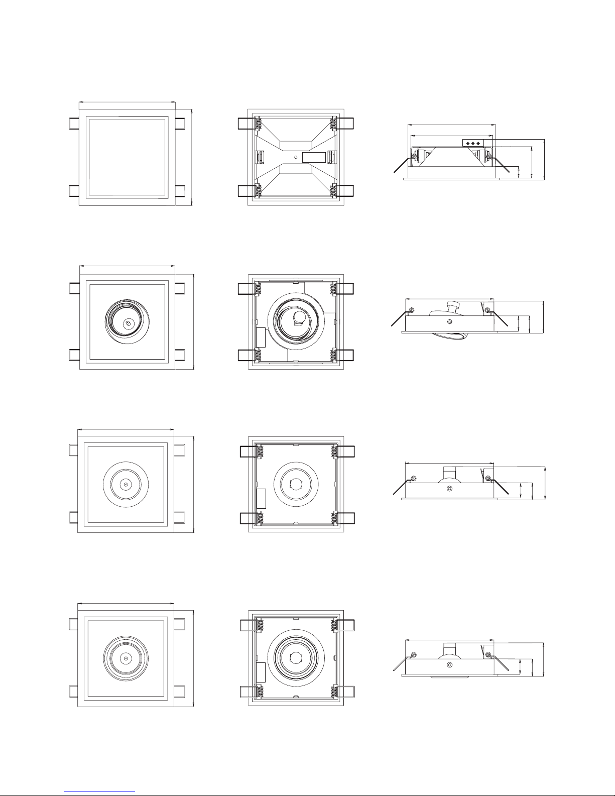
150
138
128
24
50
75
150
Œwiat³o centralne Cl1 - 100 W
150
150
138
70
27
24
Œwiat³o punktowe wywrotne SL2 - 35 W
150
150
138
70
27
24
Œwiat³o punktowe z kr¹¿kiem SL1 - 35 W
150
150
70
27
24
138
Œwiat³o punktowe sta³e SL3 - 35 W
IP 44
Wykresy rozmiarowe
-40-
Page 41

106
106
95
10
18
Zdalne sterowanie RC2 - L1
150
150
138
24
27
64
G³oœnik LS - WZB1
150
150
24
27
138
Pokrywa wentylatora
-41-
Producent zastrzega sobie prawo zmiany ceny, parametrów technicznych lub innych kwesti
bez wczeœniejszego ostrze¿enia i nie ponosi odpowiedzialnoœci za b³êdy drukarskie.
Page 42

HU
RAVAK LIVING 1 - Szerelési, és üzembe
helyezési utasítás
A jelen utasítás tartalmazza a RAVAK LIVING 1 rendszer szerelési, bekötési, és üzembe helyezési
utasításait.
Fontos
Áramütés veszélye!
Megsemmisítési intézkedések
Szerelési eljárás
Az elemek cseréje a távirányítóban
Akiégett izzó cseréje
Meghibásodások, és elhárításuk
Alkalmazott jelek:
Tartalom:
Biztonsági utasítások
Szerelés és elektromos bekötés
Arendszer üzembe helyezése
Karbantartás és szerviz
oldal
oldal
oldal
oldal
oldal
oldal
oldal
oldal
oldal
oldal
oldal
oldal
oldal
Alámpák és a ventilátor burkolatánakelhelyezése
A távirányító és a hangszóró elhelyezése
Garancia
Acsomagolóanyag kezelése, valaminta készülék megsemmisítése
az élettartama lejárata után
Használati utasítás
1. ábra: Billentyûzet
2. ábra: A lámpák elhelyezése
Bekötési vázlat
Bekötési rajz
Alapvetõ mûszaki adatok
Méretezett rajzok
Ezt az utasítást õrizze meg!
43
43
44
44
45
45
46
47
47
48
48
49
50
!
!
-42-
Page 43

Biztonsági utasítások
- A tápegység az I. osztályú elektromos készülékekre vonatkozó elõírások szerint készült, ezért ezt ennek megfelelõen
kell bekötni.
A rendszer tápellátását csak azután szabad bekapcsolni, amikor már teljesen befejezõdött az alkatrészek
beszerelése és bekötése, különbenáramütésérheti.
-
-
Az egységeket olyan helyre szerelje fel, amely szereléskor és ellenõrzéskor könnyen hozzáférhetõ,
például az állmennyezet levehetõpaneljeközelében.
- A karbantartás, illetve az eset
Szerelés és elektromos bekötés
leges szervizmunkák késõbbi elvégzéséhez a rendszert le kell tudni választani
a hálózatról. Erre a célra használható egy önálló kétpólusú kapcsoló, vagy a kétpólusú leválasztás követelményeinek
megfelelõ kombinált kismegszakító ésáram-védõkapcsoló.
- A vezérlõegységbõl egy 1,5 m hosszú kábel lóg ki, amelyet a tápegységhez kell bekötni. Avezérlõegységbõl továbbá
kilóg 2 db 2,0 méter hosszú kábel, amelyet a hangszórókhoz kell bekötni, illetve egy 2,5 méteres kábel, amely az
antenna szerepét látja el.
- A rendszer egyes alkatrészeinek az elhelyezéséhez javasoljuk, hogy rajzoljon egy egyszerû elhelyezési vázlatot,
amelyet a vásárolandó anyagokjegyzékénekaz összeállításához is használhat.
-Aközponti lámpát a mennyezetközepére, illetve a tükörhözközel szerelje fel. Amennyiben akádban olvasni is szokott,
akkor a spotlámpák fényét ide irányítsa. A spotlámpák fényét természetesen más irányba is irányíthatja, például
a mosdó felé, vagyazzala csempék domborulatának akiemelésévelkülönleges hangulatot varázsolhat stb.
-Aventilátorburkolatota fixen beépített ventilátorközelében,vagy a szellõzõnyíláshoz kellelhelyezni.
- Az egyes alkatrészeknek az álmennyezetben 140 x 140 mm-es nyílást kell kivágni, amelyben az alkatrészek rugóval
lesznek rögzítve.
- Az állmennyezet alsó részén egy kis keret takarja el a nyílás éleit. A szerelés és az ellenõrzés megkönnyítése
érdekében az alkatrészek azálmennyezetalsó felérõl kivehetõk.
- A mûködtetõ billentyûzetnek olyan helyet válasszon, ahol a rendszert kezelõ személyek azt könnyen elérhetik.
Afürdõszobában a billentyûzet felszerelését, akádban fekvõ helyzetbõl elérhetõhelyrejavasoljuk. Takarítási okokmiatt
azonban a távirányítót a kád szélétõl számítva legalább 15 cm magasra szerelje fel. A távirányítót a WC-ben, az ülõ
személy kéztávolságán belül kell elhelyezni. Javasolt, hogy az infravörös érzékelõt tartalmazó hangszóró „rálásson”
a távirányítóra, azonban ezt az építészeti megoldások nem mindig teszik lehetõvé. Az infravörös vezérlõ sugarakat
gyakran a természetes tükrözõdések is eljuttatják a közvetlenül nem látható érzékelõhöz. Az alkatrészek tényleges
szerelése elõtt azonban lekellellenõrizni a rendszer mûködõképességét.
- A távirányító hátsó felén két beépített állandó mágnes található, amelyek segítségével a mûködtetõ billentyûzetet
a fém laphoz lehet rögzíteni. A fém lapot a falhoz csavarozással, vagy kétoldalú ragasztóval lehet hozzáerõsíteni
a csempékhez, vagy más rögzítési helyhez. Amennyiben több fém lapot is felszerel, akkor a távirányító több kezelési
helyre is átrakható lesz. A távirányítót kétoldalas ragasztószalaggal közvetlenül is fel lehet ragasztani a falra. Ez
a megoldás azonban komplikációtokoza lemerült elemek cseréjekor.
-Atervekszerintaz álmennyezeten jelölje megalámpák, a hangszórók és máskiegészítõk helyét.
- Ezeken a helyekenazálmennyezetbe vágjon 140 x140mm-esnyílásokat.
-Azálmennyezet fölé szerelje felavezérlõ- és a tápegységet.
A lámpák és a ventilátor burkolatának elhelyezése:
A távirányító és a hangszóró elhelyezése:
Szerelési eljárás:
A rendszer összes elemét éghetetlen anyagból készült, jól szellõzõ álmennyezet mögé kell rejteni.Az álmennyezeten
kívülre esõ elemeket nem szabad csepegõ vagy fröccsenõ víznek kitenni. A látható oldalon az egyes elemek víznek
való ellenállását az adottelemfedésének foka (IP xx) adjameg.
- A távirányítóban található elemeket nem szabad túl magas hõ hatásának, például erõs közvetlen napsütésnek,
lángnak, vagy más hõforrásnakkitenni.
-Aterméketcsaka használati utasításban leírtcélokraszabad használni.
-Akészüléktelepítésekorbe kell tartani mindenidevonatkozószabványt és elõírást.
-Arendszertcsakmegfelelõ szakképzettséggel rendelkezõ villanyszerelõszakemberépítheti, és kötheti be.
A fal, vagy a mennyezet fúrása elõtt gyõzõdjön meg arról, hogy a falban nincs rejtett elektromos vezeték, vagy
víz- esetleg gázcsõ.
A vezérlõ egységet és a tápegységet az álmennyezet fölé a mennyezetre, esetleg az álmennyezet tartószerkezetére
kell szerelni.
-43-
Page 44

- Kösse össze a vezérlõegység konnektorát a hangszóróval. A vezérlõegység elõ van készítve egy opciós hangszóró
csatlakoztatására is.Amennyiben nem kívánja használni, akkor a bekötetlen konnektort védje a másik konnektorral és
fém tárgyakkal való érintkezéstõl. Amennyiben beköti a másik hangszórót is, akkor a másik hangszórót az elsõ
hangszóró bekötése szerint kösse be (barna vezeték a hangszóró „+” pólusára, fehér vezeték a hangszóró másik
pólusára).
- Csatlakoztassa a központi lámpát az elektromos hálózathoz. Amennyiben a meglévõ bekötést használja, akkor
a vezetéket megfelelõ mérettelmegkell hosszabbítani.
- A lámpa, a hangszóró, és az esetleges egyéb tartozékok bekötése után, a keret rugóját benyomva dugja az adott
alkatrészt a nyílásba. Akeretetszükség esetén erõsebb húzássallehetkivenni a nyílásból.
- Csavarozza le a tápegység fedelét, és bekötési rajz szerint kösse be a vezetékeket. A vezetékek hosszát kellõ
tartalékkal határozza meg.
- Amennyiben a helyzet megkívánja, illetve a helyi szabványok ezt elõírják, akkor a szabvány által specifikált
alkatrészeket a védõföldeléssel kösse össze. A védõföldeléshez, a mechanikus behatásoktól védett, sárga-zöld
szigetelésû, 2,5 mm keresztmetszetû rézvezetékethasználjon.
-Amegfelelõ védelem biztosítása érdekébenaz összekötõ vezetékekkör keresztmetszetûek legyenek. A nem használt
kimeneteket le kell szigetelni, vagy dugózni. A tápegység kábelcsatlakozásait jól meg kell húzni, a vezetékmechanikus
rögzítése, és a jóelektromosérintkezés miatt.
- A bekötések ellenõrzése, és a burkolatok felerõsítése utána rendszert kösse a hálózatra, a használatiutasítás szerint
ellenõrizzen le minden funkciót, végül az állmennyezetet mindenhol zárja le.
- Rögzítse a távirányítótakezelési helyre.
A szerelõ cég kitölti a garancialevelet, és átadja a felhasználónak a szerelési és használati utasítást. Majd
bemutatja a felhasználónak afunkciókat,és a rendszer kezelését.
A rendszer nem igényel különösebb karbantartást. A tisztításhoz karcoló tisztítószereket (kádtisztító port stb.), vagy
agresszív vegyi anyagokat (oldószert, savat, vagy lúgot tartalmazó tisztítószert) használni tilos. A rendszer
felszerelésének helyén nem szabad olyan tisztítószereket használni, amelyek a fém alkatrészekre káros hatású
gõzöket bocsátanak ki (pl. sósavat). A rendszer karbantartása elsõsorban az alkatrészek és üveg felületek enyhén
benedvesített ruhával való megtörlését jelenti. A rendszert csak kikapcsolt állapotban szabad tisztítani. Arászáradt és
makacs szennyezõdések tisztításához ajánljukaRAVAK CLEANER tisztítóanyag használatát.
Amennyiben a LED dióda (1. ábra, 8-as tétel) a távirányító gombjainak a megnyomása után nem villog, illetve
a rendszer nem reagál a távirányító gombok megnyomására, akkor az elemek lemerültek, azokat ki kell cserélni. Az
elemcseréhez használjon csavarhúzót és „AAA” típusú új elemeket. Javasoljuk, hogy használjon hosszú élettartamú
alkáli elemeket, amelyek nem folynak ki, és amelyek nem tesznek kárt a távirányító érintkezõiben és elektronikájában.
Atávirányítót vegye le afalról, csavarja kia hátlapon a kétcsavart, és vegye le az elemtartó fedelét. Ügyeljen arra, hogy
a tömítés a fedél alatt ne sérüljön meg, és legyen megfelelõen a helyén. Az elemek cseréje, és az elemtartó fedelének
a visszahelyezése után csavarjavisszaa két csavart, éspróbáljaki a távirányító funkcióit.
A távirányítóba nem kerülhet nedvesség. Amennyiben a távirányító belsejébe véletlenül nedvesség kerülne,
akkor vegye ki az elemeket, a fedelet ne szerelje vissza, a távirányítót pedig alaposan szárítsa ki (például
a központi fûtés radiátorárahelyezve).
Az egész rendszert kapcsolja le a kismegszakítóval, és várja meg, míg a lámpa teljesen le nem hûl. A tartólemez
óvatos kifelé húzásával lazítsa meg az üveglapot, enyhén hajtsa le, majd húzza ki a lámpából. A kiégett izzó
kivételéhez a kerámia foglalatot az egyik oldalon nyomja be,az izzót nyomja a másik foglalat felé, majd húzza ki.
A használati utasítás szerinti azonos típusú és teljesítményû új izzót a fentiekkel ellentétes sorrendben szerelje be.
Ahalogén izzókat puszta kézzel megfognitilos, amennyiben ez mégis megtörténne, akkor az izzóról a zsíros nyomokat
zsírtalanító készítménnyel le kell törölni. Az új izzót egy kicsit elfordítva nyomja bele az egyik foglalatba, a másik
foglalatot pedig nyomja be. Az izzót emelje a foglalat síkjába, majd a foglalatot elengedve az izzót illessze a másik
foglalatba is. Végül szerelje vissza a védõüveget. A védõüveget a keret egyik oldalán kicsit ferdén nyomja neki
a tartólemeznek, majd az üveget állítsa vízszintes helyzetbe, majd az üveg elengedése után az üveg kb. 2 mm-t
elmozdulva beugrik a keretmásikfelén is.
2
Arendszer üzembe helyezése
Karbantartás és szerviz
Az elemek cseréje a távirányítóban:
A kiégett izzó cseréje a központi lámpában:
A vezérlõegység helyzete és az antenna
megfelelõ betájolása befolyással vanarádióvétel minõségére.
!
-44-
Page 45

A kiégett izzó cseréje a spotlámpában:
Az egész rendszert kapcsolja le a kismegszakítóval, és várja meg, míg a lámpa teljesen le nem hûl. Az izzót
rögzítõ rugós drótkeretet lazítsa le, ezt követõen az izzó kivehetõ. Enyhén fordítsa el a bajonettzárban az izzót,
és azt húzza ki. Afoglalatba a használati utasításban leírtak szerinti típusú és teljesítményû izzót helyezzen be,
majd finoman fordítsa el.A foglalatba helyezett izzótbiztosítsabe a rugós drótkerettel.
ALIVING 1 elektromosberendezés, amelynek szakszerûtlenfelszerelése és alkalmazása áramütést és anyagi károkat
okozhat.Arendszerjavításátbízza villanyszerelõ szakemberre.
Amennyiben a rendszer nemmûködne,akkor a következõ ellenõrzésekethajtsavégre:
- Lemerültek az elemekatávirányítóban?
- Vantápellátása a rendszernek?
- A nem égtek ki a tápegységben a biztosítékok? A rossz biztosítékot csak azonos típusú ésértékû biztosítékkal szabad
helyettesíteni!
Amennyiben a rendszer mûködik, de a lámpa nem világít, akkor ellenõrizze le az izzót, és szükség esetén cserélje ki.
Amennyiben önerõbõl nem találja meg a hibát, akkor vegye fel a kapcsolatot a rendszer eladójával, vagy közvetlenül
a gyártó szervizével.
A rendszerre az érvényes törvényi elõírások szerint 24 hónap garanciát adunk, amely a garancialevélen feltüntetett
vétel, vagy szerelés napjával kezdõdik. A garancia csak teljesen kitöltött garancialevéllel érvényesíthetõ. A vevõ
a garanciára valóigényét a garancialevélen feltüntetetteladónál köteles bejelenteni. Agaranciaidõ a garanciális javítás
idõtartamával automatikusan meghosszabbodik, amennyibenareklamációt az elbíráló jogosultnakismeriel.
A termék hibájára vonatkozó termékfelelõsség amelyre a garancia vonatkozik elévül, amennyiben az a garanciaidõn
belül nem került bejelentésre. A gyártó elutasítja azokat a kártérítésre vonatkozó igényeket, amikor a kárt a vevõ, vagy
harmadik személy a beépítésielõkészületekre vonatkozó követelmények, agyártóelõírásai, és a használatiutasításbe
nem tartásával, valamint a dokumentációban leírt elõírásoktól eltérõ szakszerûtlenszerelésekkel és karbantartásokkal
okoztak a rendszeren.
A garancia a termék tulajdonságaira, funkcióira, kivitelére, és a felületi minõségére vonatkozik. A garancia nem
vonatkozik a szakszerûtlen szereléssel, a használati utasítástól eltérõ használattal, a helytelen karbantartással, vagy
a nem alkalmazható tisztítószerek használatával okozott károkra és sérülésekre. Továbbá a garancia nem vonatkozik
a normál használatból eredõ kopásokra, mechanikus vagy más jellegû sérülésekre, a nem megfelelõ típusú elemek
használatából keletkezõ sérülésekre, a készülék kivitelével nem összeegyeztethetõ helytelen, vagy extrém
körülmények közötti alkalmazásra visszavezethetõ meghibásodásokra. A vezérlõegység plombájának sérülése, vagy
a rendszer módosítása eseténagaranciális javításra vonatkozó kérelemellesz utasítva.
Agyártó fenntartja magának ajogot a termék folyamatos fejlesztésére.Egyéb részletes információkat azeladónál, vagy
a gyártó honlapján. www.ravak.cz, www.ravak.com, illetve a 844844 874 telefonszámon szerezhet.
A csomagolóanyag felhasználható elemeit (kartondoboz, hullámpapír, PE fólia) használja el Ön más célokra, vagy
dobja az anyagnak megfelelõ hulladékgyûjtõ konténerbe. A fel nem használható csomagolóanyagokat, illetve
a terméket azélettartamalejárta után, az idevonatkozókörnyezetvédelmi elõírások szerint semmisítsemeg, illetve adja
le újrahasznosításra.
Aterméken, vagy a terméketkísérõ dokumentáción feltüntetett jelaztjelenti, hogy az elektromosés elektronikus
hulladékot és berendezéseket aháztartási hulladékok közé kidobni tilos. Az újrahasznosítás érdekébenezeket
a termékeket a kijelöltgyûjtõhelyenadja le.
Az elektromos és elektronikus berendezések begyûjtésérõl és megsemmisítésérõl kérjen információt az
eladótól, vagy a termékforgalmazójától.
Meghibásodások, és elhárításuk
Garancia:
Acsomagolóanyag kezelése, valamint akészülékmegsemmisítése az élettartama lejárata után
Az elektromos és elektronikushulladékokkezelésére vonatkozó információk
!
-45-
Page 46

A LIVING 1 távirányítóval mûködtetni lehet az URH rádió vételét és hallgatását, a két világítási kör kapcsolását, és
a ventilátor idõzítését. A rendszer tápegységbõl, vezérlõegységbõl, infravörös érzékelõvel szerelt hangszóróból és
távirányítóból áll. A rendszerhez külön lehet vásárolni kiegészítõ hangszórót, külsõleg kapcsolt központi lámpát,
spotlámpákat, távirányítót a másodiklámpakörmûködtetéséhez, illetve ventilátor burkolatot.
A LIVING 1 rendszerrel két lámpakört lehet vezérelni. Az RC1-L1 távirányító az „A” lámpakört, az RC2-L1 távirányító
a „B” lámpakör mûködését vezérli.Az 1-es gomb rövid megnyomásával az adott lámpakört be lehet kapcsolni. Az 1-es
gomb újbóli megnyomásával a lámpakört ki lehet kapcsolni. A gomb egy másodpercnél hosszabb ideig tartó
benyomásával mindkét lámpakört egyidejûlegkilehet kapcsolni.
A 2-es gomb elsõ megnyomásával bekapcsolja a ventilátort, és azt 5 percig mûködteti. A második megnyomás
a ventilátor mûködését 10 percre, a harmadik gombnyomás 15 percre hosszabbítja meg. A negyedik gombnyomás törli
az idõbeállítást, és aventilátortkikapcsolja.
A 3-as gomb megnyomásával a rádió bekapcsol, és az utoljára beállított állomás adását játssza le. A3-as gomb újbóli
megnyomására a rádió kikapcsol.Arádió kikapcsolásakor abehangolt frekvencia ésa beállított hangerõ a memóriában
tárolódik.Amemóriaáramszünetalatt is megõrzi tartalmát.
A hangerõ a teljes kikapcsolástól a maximális értékig állítható be. A 4-es gombbal (+) a hangerõt fokozni, az 5-ös
gombbal (-) a hangerõt csökkenteni lehet. A gombok rövid megnyomásával egy fokozattal csökkenteni (), vagy növelni
(+) lehet a hangerõt. A gombok folyamatos nyomásával gyorsabban lehet csökkenteni (-), vagy növelni (+) lehet
a hangerõt.
A bekapcsolt rádiót a 6-os és 7-es gombok segítségével lehet másik állomásra áthangolni. A rádióadók keresését
kétféle módon lehet elvégezni, ezek a módok csak a gombok megnyomásának hosszában térnek el egymástól
(„hosszú” és „rövid”).
Általában az elsõ módot ajánljuk, amelya legtöbb esetbenjól mûködik. A 6-os gomb hosszú megnyomásával elindul az
automatikus hangolás a magasabb frekvenciák felé (a 7-es gomb megnyomásával az alacsonyabb frekvenciák felé).
Hangolás közben a hangerõ automatikusan kikapcsol, de a rádióállomás behangolása után visszaáll a korábban
beállított értékre. Amennyiben a hangolás során a készülék eléri a frekvenciasáv felsõ határértékét, akkor a keresést
a frekvenciasáv alsó határértékétõl felfelé folytatja tovább (ellenkezõ irányú hangolásnál az alsó határértékrõl a felsõre
ugrik át). A hangolást végzõ áramkör érzékeny, ezért elõfordulhat, hogy fals (zavaró) jelekre is behangol. Ilyenkor
a gomb hosszú benyomásával folytathatja a keresést tovább. Amennyiben az egész frekvenciasávban nem talál
kellõen erõs jelû rádióadótahangoló áramkör,akkor a keresés elõttbeállítottadót fogja ismételten lejátszani.
A másik keresési üzemmód a 6-os és 7-es gombok rövid benyomásával (lépésekkel) mûködtethetõ. A rövid
gombnyomásos keresõ léptetést másodpercenként legfeljebb 3-szor lehet megismételni, különben a készülék hosszú
gombnyomásnak fogja kiértékelni. A6-os gomb egy rövid megnyomásával a frekvencia 50 kHz-es lépéssel emelkedik
(a 7-es gomb egy rövid megnyomásával a frekvencia 50 kHz-es lépéssel csökken). Ezt a hangolási módot akkor
javasoljuk, ha két erõs jellel sugárzó adó túl közel van egymáshoz (finomhangolás), vagy ha a jelek gyengék, illetve
zavartak (kézi hangolás).
AkijelzõLED dióda a távirányítómûködõképességét,valamint a parancsjelek küldésétjelziki.
A LIVING 1 rendszert csak a távirányító mûködteti.
Ez a funkció kikapcsolja a rádiót és
a lámpaköröket, amennyiben atávirányítógomb utolsó megnyomásától 120perceltelt.
A központi lámpa a meglévõ világítási vezetékre lesz bekötve, és az ajtó közelében elhelyezett kapcsolóval lesz
mûködtetve.
ALIVING 1 rendszer mûködtetése(aszámok az 1. ábra szerintimûködtetõ elemeket jelölik).
1. Világítás ON/OFF bekapcsolva/kikapcsolva
2. Ventilátor ON/OFF bekapcsolva / kikapcsolva
3. Rádió ON/OFF bekapcsolva /kikapcsolva
4. és 5. Hangerõszabályozása Volume -, Volume + (vol.)
6. és 7. Rádióhangolása Tuner (tun.)
8. Kijelzõ LED dióda
Önmûködõ rendszerkikapcsolás
Központi lámpa
A rendszer folyamatos mûködését a távirányító elemeinek
a lemerülésekor a rendszer automatikus kikapcsolással akadályozza meg.
HU
RAVAK LIVING 1 - Használati utasítás
-46-
Page 47

2. ábra: A lámpák elhelyezése
1. ábra: Billentyûzet
8
3
4
5
6
7
1
2
Az SL és CL spotlámpák szereléséhez a mennyezet és
az álmennyezet között legalább 80 mm
távolságnak kell lennie.
fix mennyezet
gipszkarton
80 mm
-47-
Page 48

Bekötési rajz
Bekötési vázlat
CC-L1
LNZ1
TÁPEGYSÉG
VEZÉRLÕEGYSÉG
LS-WZA1
LS-WZB1
„A ” LÁMPAKÖR
VENTILÁTOR
ANTENNA
VÉDÕFÖLDELÉS
CL1
RC1-L1
RC2-L1
Az „A” lámpakört az RC1-L1
távirányítóval, a „B” lámpakört az
RC2-L1 távirányítóval lehet
mûködtetni.
Az „A” és „B” lámpakörökre az
SL1, SL2, CL1 lámpák
valamelyikét lehet rákötni, vagy
más 230 V-os lámpát, de
a lámpakör teljesítményfelvétele
nem haladhatja meg a 220
W/lámpakör értéket. A lámpák
védelmi fokozata (IP xx) feleljen
meg az adott zónára elõírt
védelemnek.
A szaggatott vonallal
megjelölt alkatrészek
opciósak, ezek nem részei az
alapkészletnek.
A teli vonallal megjelölt
alkatrészek az alapkészlet
részei.
hosszúság 2,0m
hosszúság
2,5m
hosszúság 2,0m
hosszúság 1,5m
ÁRAM-
VÉDÕKAPCSOLÓ
KÉTPÓLUSÚ
KAPCSOLÓ
I = 30mA
0
2.5 mm
2
CYKY 3Cx1.5 mm
2
TN-S
230V~50Hz
CC-L1
LNZ1
VEZÉRLÕEGYSÉG
LS-WZA1
6
7
8
9
10
11
12
13
14
15
16
17
18
1
J1
1
2
3
2
3
4
5
N
N
N
N
L
L
V
L
A
+14V
0V
()fehér
()szürke
()barna
()kék
()barna
()sárga-zöld
()sárga
()zöld
YE
GY
YEGN
YEGN
WH
GN
BN
BU
BN
ANTENNA
CYKY 3Cx1.5 mm
2
2.5 mm
2
N
L
A
()kék
YEGN
BU
BN
()barna
N
L
V
PGM
INFRA
PWR
YEGN
()barna
BN
BU
()kék
CL1
()kék
()barna
YEGN
BU
BN
N
L
LS-WZB1
()kék
()barna
YEGN
BU
BN
N
L
B
L
B
I = 30mA
0
F1T50mA L
F2 T1A L
1 HANGSZÓRÓ
2 HANGSZÓRÓ
TN-S
230V~50Hz
„B ” LÁMPAKÖR
„A ” LÁMPAKÖR
VENTILÁTOR
„B ” LÁMPAKÖR
TÁPEGYSÉG
VÉDÕFÖLDELÉS
ÁRAM-
VÉDÕKAPCSOLÓ
KÉTPÓLUSÚ
KAPCSOLÓ
-48-
Page 49

Alapvetõ mûszaki adatok
Lámpakör (A)
Lámpakör (B)
Rádió (a CC-L1 része)
Hangszóró (LS-WZA1)
Tápegység (LNZ1)
Ventilátor (nem tartozék)
Alapvetõ mûszaki adatok kiegészítõk
Központi lámpa (CL1-100W)
Fix spotlámpa közgyûrûvel (SL 1-35W)
Spotlámpa, billenthetõ (SL2-35W)
Spotlámpa, fix (SL3-35W)
Hangszóró (LS-WZB1)
Távirányító (RC2-L1)
Ventilátor burkolat
Gyártó: RAVAK a.s., Obecnická 285, Pøíbram
A rendszer maximális teljesítményfelvétele: 550 W
Feszültség : 230 V, 50 Hz
Névleges feszültség: 230 V, 50 Hz
Maximális teljesítményfelvétel: 220 W
Névleges feszültség: 230 V, 50 Hz
Maximális teljesítményfelvétel: 220 W
Specifikáció: URH rádió
Frekvenciaterjedelem: 87,5 108,0 MHz
Antenna: drót URH antenna
Névleges teljesítmény: 6 W
Névleges impedancia: 4
Feszültség : 230 V, 50 Hz
Maximális saját teljesítményfelvétel: 10 W
Egyenfeszültség: 14 V
Egy lámpakör maximális terhelhetõsége: 220 W
Maximális teljesítményfelvétel: 100 W
Feszültség : 230 V, 50 Hz
Fényforrás: Halogén izzó, J 78
Névleges feszültség: 230 V, 50 Hz
Teljesítményfelvétel: 100 W,
Védettség IP 20
Fényforrás: Halogén izzó, GU 10
Névleges feszültség: 230 V, 50 Hz
Teljesítményfelvétel: 35 W,
Védettség IP 20
Fényforrás: Halogén izzó, GU 10
Névleges feszültség: 230 V, 50 Hz
Teljesítményfelvétel: 35 W,
Védettség IP 20
Fényforrás: Halogén izzó, GU 10
Névleges feszültség: 230 V, 50 Hz
Teljesítményfelvétel: 35 W,
Védettség IP 44
Névleges teljesítmény: 6 W
Névleges impedancia: 4ÙÙ
Ugyanaz, mint a RC1-L1, a „B” lámpakört mûködteti
Nem elektromos termék
-49-
Page 50

150
138
128
24
50
75
150
Központi világítás, CL1- 100 W
150
150
138
70
27
24
Spotlámpa, billenthetõ, SL2 - 35 W
150
150
138
70
27
24
Spotlámpa, közgyûrûvel, SL1 - 35 W
150
150
70
27
24
138
Spotlámpa, fix, SL3 - 35 W
IP 44
Méretezett rajzok
-50-
Page 51

106
106
95
10
18
Távirányító RC2 - L1
150
150
138
24
27
64
Hangszóró LS - WZB1
150
150
24
27
138
Ventilátor burkolat
-51-
A gyártó fenntartja magának a jogot az ár, a mûszaki paraméterek, továbbá egyéb tulajdonságok elõzetes bejelentés nélküli megváltoztatására,
továbbá a gyártó nem vállal felelõsséget az esetlegesen elõforduló sajtóhibákért.
Page 52

RU
RAVAK LIVING 1 - Руководство по установке
и вводу в эксплуатацию
В настоящем руководстве описывается установка, подключение и ввод в эксплуатацию системы
Внимание
Осторожно напряжение!
Утилизация устройства
ñòð.
Замена батарейки в дистанционном управлении
Замена лампочки
Возможные неисправности и их отстранения
RAVAKLIVING 1.
Используемые знаки
Содержание
Правила техники безопасности
Установка и подсоединение к электроэнергии
Ввод системы в эксплуатацию
Уход и сервисное обслуживание
:
:
стр.
Установка освещения и крышки вентилятора
Установка дистанционного управления и громкоговорителя
Порядок установки
ñòð.
ñòð.
ñòð.
ñòð.
ñòð.
ñòð.
ñòð.
ñòð.
ñòð.
ñòð.
ñòð.
Гарантия
Обращение с упаковочным материалом и с продукцией по
завершению срока службы
Руководство по использованию
Рисунок 1: Клавиатура
Рисунок 2: Расположение освещения
Основная схема
Схемасоединений
Основные технические параметры
Чертежи
Настоящее руководство бережно храните!
53
53
54
54
55
55
56
57
57
58
58
59
60
!
!
-52-
Page 53

Правила техники безопасности
Установкаи подсоединение к электроэнергии
-
-
- 1,5
2,5 .
-
-
-
- 140 x 140 ,
-
-
IR
IR
-
Блок питания сконструирован при соблюдении требований, предъявляемых в приборам класса 1, и его
подсоединениедолжновыполняться в соответствиис этим.
Подключение системы к питанию возможно только после полного подсоединения и завершения
монтажных работ, в противном случае возможно поражение электрическимтоком.
Подходящее место установки выбирайте с учетом доступности выполнения
монтажа и проведения контролей, лучше всего там, где можно снимать части подвесного потолка.
С учетом ухода и возможного сервисного обслуживания оборудования, система должна отключаться от
питания. В этих целях можно использовать отдельный двухполюсный разъединительный элемент или
защитный выключатель тока в сочетании с защитным электрическим автоматом, отвечающие требованиям по
двухполюсномуотключению.
От управляющего устройства отходит кабель длиной м, предназначенный для соединения с блоком
питания. А также от управляющего устройства отходят 2 кабеля длиной 2,0 м для подключения
громкоговорителейикабельантенны длиной ì
Для установки отдельных предметов мы рекомендуем предварительно составить проект или эскиз, которые
одновременно послужат для составления списка материала и закупки деталей.
Центральное освещение находится в центре потолка, поближе к зеркалу. Если в ванне Вы будете читать, то
необходимо точечное освещение направить в эту область. Их также можно направить на умывальник или
другие места, которые хотите в ванной комнате подчеркнуть, например, рельеф наоблицовочной плитке и т.п.
Крышку вентилятора лучше поместить возле стабильно установленного вентилятора или вентиляционной
шахты.
Деталиустанавливаются в отверстия подвесногопотолка мм в которых закрепляются пружиной.
С лицевой стороны отверстие в подвесном потолке закрывает рамка. Для установки и контроля лампы
и остальные предметы можно вынимать с наружной стороныподвесного потолка.
Однако с учетом уборки в ванной оно должно находиться на
высоте минимально 15 см от края ванны. В туалете дистанционное управление размещается в зоне
досягаемости сидящего человека. Рекомендуется, чтобы громкоговоритель с сенсором находились в прямой
видимости с дистанционным управлением, однако, строительная ситуация не всегда это позволяет.
Бесперебойная передача сигналов управления очень часто получается также в результате естественного
отражения без прямой видимости. Однако необходимо перед окончательной установкой деталей проверить
полное функционирование системы.
В задней части дистанционного управления установлены два сильных магнита, при помощи которых
дистанционное управление держится на металлической пластине. Эту пластину можно привинтить к стене или
же наклеить на облицовочную плитку при помощи двухстороннего скоча и т.п. Установив несколько пластинок,
можно перемещать дистанционное управление с одного места на другое. Дистанционное управление также
можно непосредственно наклеить на облицовочную плитку припомощи двухстороннегоскоча.Однако, при этом
способе решения возникают проблемы во время заменыбатарейки.
Перед тем как сверлить стены или потолок, убедитесь в том, что под поверхностью не находятся
электропроводка, водопроводныеилигазовыетрубы.
Установка освещения и крышки вентилятора
Установка дистанционного управления и громкоговорителя::
- Все элементы системы должны быть закрыты пожаробезопасным проветриваемым подвесным потолком. На
элементы, находящиеся над уровнем подвесного потолка, не должна попадать капающаяили разбрызгиваемая
вода.С лицевой стороны водостойкость определена степенью защиты (IP xx) данного элемента.
- Батарейки, используемые в дистанционном управлении, не должны подвергаться чрезмерным
температурами,например, воздействию солнечногоизлучения,огняи т.п.
- Продукция должна использоватьсяисключительновнижеуказанных целях.
- Во время установки и эксплуатации необходимо соблюдать все соответствующие действующие нормы
и предписания.
- Установку и ввод в эксплуатацию должен выполнять специалист, имеющий соответствующую
электротехническуюквалификацию.
- Управляющее устройство и блок питания крепятся к потолку над подвесным потолком или на несущую
конструкцию подвесного потолка.
Для установки управления заранее выберите самое подходящее место , которое будет удобно как для Вас,
так и для остальных пользователей. В ванной комнате его лучше всего разместить на стене над ванной на
высоте, досягаемой из положения лежа в ванне.
-53-
Page 54

Порядок установки
Замена батарейки в дистанционном управлении
Замена лампочки в центральном освещении
:
:
:
-
- 140 x140 .
- .
- .
.
“+”
).
-.
-
-
-
-
(1 8)
“AAA”.
.
2
В соответствии с проектом разметьте на подвесном потолке места установки освещения, громкоговорителей
и других дополнений.
Вырезатьв подвесномпотолкеотверстия мм
В промежуточное пространство установить управляющее устройство и блок питания
Кабель от управляющего устройства с коннектором подсоедините к громкоговорителю Управляющее
устройство готово к любому подключению дополнительного громкоговорителя Если этим не воспользуетесь, то
неиспользованные коннекторы необходимо оградить от контакта с металлическими предметами. Если Вы
захотите подключить второй громкоговоритель, то соединение обоих громкоговорителей по цвету должно быть
одинаковым (коричневый провод к контакта громкоговорителя, а белый провод к другому контакту
громкоговорителя
Подключитецентральное освещение к осветительной проводке Если используетесуществующуюпроводку, то
кабель необходимовдостаточной степениудлинить.
После подсоединения освещения, громкоговорителя или иного дополнения придержите зажимные пружины на
рамке и вставьтедеталь в отверстие в подвесном потолке. Деталь демонтируется,потянувза рамку.
Отвинтить крышку блока питания и соедините согласно схеме подводящими кабелями с достаточным запасом
длины.
Все соединительные кабели должны иметь круглое сечение для соблюдения достаточной степени защиты. На
неиспользуемые выводы необходимо установить запасные заделки. Все кабельные выводы блока питания
необходимо тщательно подтянуть в целях механического крепления кабелей и соблюдения указанного класса
защиты.
-
.
Монтажная организация заверит гарантийный паспорт, передаст пользователю руководство по установке
и руководство по обслуживанию и ознакомит пользователя с функциями и обслуживаниемсистемы.
Если сигнальный светодиод на Рисунке обозначен цифрой на дистанционном управлении при нажатии на
кнопку не мигает либо оборудование не реагирует на нажатия на кнопки дистанционного управления, то
необходимо заменить батарейки. Для замены используйте отвертку и две новые батарейки Мы
рекомендуем использовать качественные щелочные батарейки, которые не загрязнят и не повредят контакты
держателяи электроники дистанционного управления. Снять дистанционное управление, отвинтитьдвавинта на
задней стороне, снять крышку и заменить батарейки. Проверить целостность и правильное положение
уплотнения под крышкой. Закрыв крышкой батарейки, привинтить оба винта и проверить работу дистанционного
управления
Во внутрь дистанционного управления не должна попадать вода или влажность. В случае случайного
попадания влажности, необходимо вынуть батарейки и дистанционное управление со снятой крышкой
оставить сохнуть (в слегкатепломсухом месте, например, на радиаторе центрального отопления).
Обеспечьте отключение всей системы и подождите, пока не остынут все перегоревшие лампочки.
Осторожно потянув за металлическую пластинку по направлению от края лампы разъедините стекло,
затем слегка наклонить и вынуть стекло. Демонтаж перегоревшей лампочки выполняется нажатием на
керамический держатель с одной стороны и одновременным нажатием налампочку в сторону противоположного
держателя. Новую лампочку того же типа и мощности, рекомендуемую в руководстве, установите в обратной
последовательности. К лампочке не прикасаться пальцами, а в случае, если это произойдет, очистить лампочку
обезжиривающим средством. Новую лампочку, слегла отклоненную от оси по сравнению с конечной позицией,
вдавливайтев один держательпри одновременно сжатии второго держатель. Потом лампочку выровняйте до оси
держателей и ослабьте силу, которая раздвигает держатели друг от друга. В заключении установите защитное
стекло. Надавив на металлическую пластинку, вставьте слегка наклоненное стекло в одну сторону рамки,
выровняйте его, и ненажимая на стекло примерно на мм также«въедете» со стороны металлической пластинки
в отверстие для рамки.
Ввод системы в эксплуатацию
Уходи сервисное обслуживание.
Если это необходимо с учетом местной ситуации и действующих норм, то проверьте соединение с защитными
проводами и всеми предметами, специфицированными в нормах. Для соединения используйте механически
защищенный медный провод с сечением 2,5 мм2 и желто-зеленойизоляцией.
После проверки соединения и креплениякрышек,подсоединитесистемук сети, еще раз проверьтевсехфункции
в полном объеме согласно Руководству по обслуживанию и закройте подвесной потолок Качество приема
сигнала можно улучшить, изменяя положение управляющего устройства и направление антенны.
- Окончательноприкрепите дистанционное управление.
Для оборудования не нуждается в специальном уходе. Для очистки запрещается использовать абразивные
средства (например, шлифовальные пасты и т.п.), а также агрессивные химические вещества (содержащие
растворители, кислоты и щелочи). В помещении, в котором установлено оборудование, запрещено использовать
моющие средства, испарения которых агрессивно воздействуют на металлические части (например, соляная
кислота). Текущий уход состоит только из протирания влажной тряпочкой деталей и стекла (систему необходимо
отключить). Для удаления старых, въевшихся загрязнений мы рекомендуем использовать моющее средство
RAVAKCLEANER.
!
-54-
Page 55

Замена лампочки в точечном освещении:
!
Обеспечьте отключение всей системы и подождите, пока не остынут все перегоревшие лампочки.
Разъединив упругий проволочный предохранитель под лампочкой, можно вынимать лампочку вниз.
Слегка повернув штыковой патрон, перегоревшую лампочку отсоедините. Вместо нее в патрон вставьте
и повернув закрепите новую лампочку, тип и мощность которой рекомендованы в руководстве. Лампочку
вставьте вдержательи закрепите проволочным предохранителем.
LIVING 1 - это электрическое устройство и в случае непрофессиональной манипуляции возможно поражение
электрическим током и возникновение материальных ущербов. Ремонт должен выполнять специалист,
имеющий право выполнять данные работы.
Если система не работает, то необходимо проверить:
- батарейкив дистанционном управлении;
- если в оборудование поступает электроэнергия;
- если работают оба предохранителя в блоке питания (замена предохранителей только такой же моделью
и с такой жевеличиной).
Если система реагирует, а свет не горит, то необходимо проверить и в случае необходимости заменить
лампочку. Если не удастся найти и отстранить неисправность, то, пожалуйста, обращайтесь к продавцу или
непосредственнов сервисный центр нашего производственного предприятия.
Согласно действующему законодательству на продукцию предоставляется гарантия сроком 24 месяца со дня
получения товара покупателем, указанного в гарантийном паспорте как дата продажи или дата установки
продукции. Гарантия действительна только при надлежащем оформлении гарантийного паспорта. Заказчик
обязан предъявлятьтребованияпо гарантии у продавца, указанного вгарантийномпаспорте.Гарантийныйсрок
продляется на срок, в течение которого продукция находилась на рассмотрении рекламации и рекламация
была признана правомерной.
Права по ответственностиза дефект вещи, на которую распространяются гарантийные условия, прекращаются,
если не были предъявлены в течение гарантийного срока. Производитель не признает никакие претензии по
возмещению ущерба за возможный ущерб, причиненный покупателем или третьим лицом в результате
несоблюдения строительной подготовки и всех инструкций производителя, указанных в руководстве по
обслуживанию, установке и уходе за продукцией ив остальных документах.
Гарантийраспространяется на все полезные функции, свойства продукции, ее вид икачествоповерхности.
Гарантий не распространяется на дефекты, возникшие в результате непрофессионального монтажа,
в результате использования в противоречии с руководством по обслуживанию и в результате неправильного
ухода, технического обслуживания и использования неподходящих моющих средств. А также гарантия не
распространяется на износ продукции, превышающий рамки обычного использования, механическое или иное
повреждение продукции, на повреждение, вызванное использованием неподходящих батареек,
и использование продукции в неправильных или чрезвычайных условиях. Гарантия недействительна в случае
повреждения пломбы на управляющем устройстве или жев случае вмешательствавпродукцию.
Производитель оставляет за собой право на регулярную инновацию продукции. Подробную информацию
о продукции Вы можете получить у своего продавца или по адресу: www.ravak.cz, www.ravak.com, или по
телефону:844 844 874.
Пригодными к вторичному использованию компонентами упаковки, например, картоном, бумажной лентой
с клеем или полиэтиленовой пленкой воспользуйтесь сами или предложите для дальнейшего использования
или утилизации. Непригодные к вторичному использованию компоненты упаковок и продукцию по завершению
сроку службы необходимо безопасным способом утилизировать согласно действующему закону об отходах.
Указанные знак на продукции или в сопроводительной документации означает, что отработанная
электронная или электрическаяпродукцияне утилизируетсясовместно с коммунальнымиотходами. Для
правильной утилизации продукцию необходимо сдать в специальные пунктыприема.
Для правильной утилизации электронного или электрического оборудования требуйте подробную
информацию у Вашего продавца или поставщика.
Возможныенеисправностии их отстранения
Гарантия
Обращение с упаковочным материалом и с продукцией позавершениюсрока службы
Информация для пользователейпо утилизации электрического или электронного оборудования
!
-55-
Page 56

Устройство с дистанционным управлением позволяет осуществлять прием радиосигнала ,
переключение двух цепей освещения и регулировку времени работы вентилятора. Состоит из двух блоков
питания, управляющего устройства, громкоговорителя с инфрадетектором и дистанционного управления. По
желанию можно купить дополнительный громкоговоритель, центральное освещение с наружным включением,
точечное освещение, дистанционное управление для управления второй цепью освещения, а в случае
необходимости,крышкувентилятора.
Комплект позволяет осуществлять управление двумя цепями освещения Дистанционное управление
RC1-L1 управляет цепью освещения “A”, а дистанционное управление RC2-L1 - цепью освещения При
быстром нажатии на кнопку 1 загорится соответствующая цепь освещения, а в результате повторного нажатия на
кнопку 1, цепь отключится. При нажатии на кнопку в течение одной секунды, обе цепи освещения отключатся
одновременно.
При первом нажатии на кнопку 2 вентилятор включается и настраивается его отключение через 5 минут. При
втором нажатии время работы вентилятора увеличивается на 10 минут, а при третьем нажатии на 15 минут.
Четвертымнажатиемнакнопку 2 преждевременно прекращается отсчетвремении вентилятор отключается.
Нажав на кнопку 3, радио включается на последней выбранной (настроенной) радиостанции. В результате
повторного нажатия на кнопку 3, радио выключается и автоматически сохраняется в памяти частота и громкость
радиостанции. Содержаниепамяти сохраняетсяи в случае прекращения подачи электроэнергии.
При быстром нажатии на кнопку уменьшится или увеличится
громкость на один уровень. В результате постоянного нажатия на кнопку можно плавно уменьшать/усиливать
громкость до необходимогоуровня.
Включенный приемник можно перенастроить на любую станцию при помощи кнопок и Поиск станции можно
выполнять двумя способами, при этом все зависит от продолжительности нажатия на кнопки быстрое
и продолжительное нажатие
Первый способ является рекомендуемым и в большинстве случаев достаточен. В результате продолжительного
нажатия на кнопку 6 «включается» автоматическая настройка по направлению к высшим частотам, а при
продолжительном нажатии на кнопку 7 осуществляется настройка по направлению к низким частотам. Во время
настройки звук радио приглушен, но когда будет найден довольно сильный сигнал, громкость возобновляется.
Если во время настройки будет достигнута граница полосы , то настройка продолжается с противоположного
конца в том же направлении (т.е. постоянно к низким или постоянно к высоким частотам). Цепь, которая управляет
автоматическим поиском станций является чувствительной и может остановиться на ложном сигнале помехи.
В таком случае на основе повторного продолжительного нажатия запустим дальнейший поиск. Если на всей
полосе не будетнайдетдостаточно сильный сигнал, то возобновляетсяпоследняянастроеннаячастота.
Второй способ настройки пошаговый при помощи быстрых нажатий на копки 6 и 7. Быстрые нажатия не должны
быть чаще 3-х нажатий в секунду, иначе будут восприниматься как продолжительные. В результате быстрого
нажатия на кнопку 6 принимаемая частота всегда увеличивается на кГц а при нажатии на кнопку 7, наоборот,
принимаемая частота всегда уменьшается на 50 кГц. Этот способ рекомендуется использовать, например,
в случае двух одинаковых по силе станций, находящихся близко, или удаленных слишком слабых или же
с помехами станций.
Индикаторный светодиод предназначен для контроля работы дистанционного управления и сигнализирует
передачууправляющихсигналов.
Управление системой осуществляется только при помощи дистанционного управления. Во избежание
постоянной работы в случае разрядки батареек, система имеет функцию автономного отключения. Все функции
цепь освещения и радио будутотключены через минутотпоследнегонажатиянакнопку.
Центральное освещение будет подсоединено к существующей проводке для освещения помещения и его
управление осуществляется выключателем,находящимсявозле входных дверей.
LIVING 1 FM
LIVING 1 .
“B”.
(+)
(-)
(-) (+)
67.
(“ ”
“”).
FM
,
50 ,
LIVING 1
( ) 120
Управление системой пронумерованные позиции соответствуют обозначению кнопок на экране
¹1)
Освещение включить / выключить
Вентилятор включить / выключить
Радио ON/OFF включить / выключить
4 и 5 Настройкагромкости
è Просмотр полосачастот
Индикаторный светодиод
Автономное отключениесистемы
Центральное освещение
LIVING 1 (
.
1. ON/OFF
2. ON/OFF
3.
Volume -, Volume+ (vol.)
6 7. Tuner (tun.)
8
Громкость непрерывно регулируется от минимального (приглушенного) до максимально уровня. Кнопка
4 непрерывно увеличивает громкость с настроенного до максимального уровня. Кнопка 5 громкость
уменьшается до минимального значения.
RU
RAVAK LIVING 1 - Руководство по
использованию
-56-
Page 57

Рисунок 2: Расположение освещения
Рисунок 1: Клавиатура
8
3
4
5
6
7
1
2
Минимальный размер установки подвесного
потолка от прочной конструкции потолк
для освещений SL и CL 80 мм
прочная конструкция потолка
гипсокартон
80 mm
-57-
Page 58

Схема соединений
Основная схема
CC-L1
LNZ1
БЛОК ПИТАНИЯ
УПРАВЛЯЮЩЕЕ УСТРОЙСТВО
LS-WZA1
LS-WZB1
ЦЕПЬ
ОСВЯЩЕНИЯ
“A”
ЦЕПЬ
ОСВЯЩЕНИЯ
“B”
ВЕНТИЛЯТОР
АНТЕННА
ВОЗМОЖ. СОЕД-ИЕ
CL1
RC1-L1
RC2-L1
Управление цепью освещения
возможно дистанционным
управлением RC1-L1,
а управление цепьюосвещения
дист.управлением
К цепям освещения можно
подключить любоеосвещение SL1,
или жедругое освещение
230В с общей потребляемой
мощностью, не превышающей
220Вт/цепь. Класс защиты
освещения ) долженотвечать
соответствующим зонам
и действующим предписаниям.
“A”
“B”
RC2-L1.
“A”, “B”
SL2, CL1,
(IP XX
Штрихованные компоненты по
желанию и не входят
в комплект поставки.
Полные компоненты входят
в основное оснащение
длина 2,0m
длина 2,5m
длина
2,0m
длина 1,5m
ÇÀÙ. ÂÛÊË.
ÒÎÊÀ
ДВУХПОЛ.
ÂÛÊË.
I = 30mA
0
2.5 mm
2
CYKY 3Cx1.5 mm
2
TN-S
230V~50Hz
CC-L1
LNZ1
БЛОК ПИТАНИЯ
УПРАВЛЯЮЩЕЕ УСТРОЙСТВО
LS-WZA1
6
7
8
9
10
11
12
13
14
15
16
17
18
1
J1
1
2
3
2
3
4
5
N
N
N
N
L
L
V
L
A
+14V
0V
()белый
()серый
()коричн.
()голубой
()коричн.
()желто-зел.
()æåëò.
()зеленый
YE
GY
YEGN
YEGN
WH
GN
BN
BU
BN
CYKY 3Cx1.5 mm
2
2.5 mm
2
N
L
A
()голубой
YEGN
BU
BN
()коричн.
N
L
V
PGM
INFRA
PWR
YEGN
()коричн.
BN
BU
()голубой
CL1
()голубой
()коричн.
YEGN
BU
BN
N
L
LS-WZB1
()голубой
()коричн.
YEGN
BU
BN
N
L
B
L
B
I = 30mA
0
F1T50mA L
F2 T1A L
REPRO 1
REPRO 2
TN-S
230V~50Hz
АНТЕННА
ЦЕПЬ
ОСВЯЩЕНИЯ
“A”
ЦЕПЬ
ОСВЯЩЕНИЯ
“B”
ВЕНТИЛЯТОР
ВОЗМОЖ. СОЕД-ИЕ
ÇÀÙ. ÂÛÊË.
ÒÎÊÀ
ДВУХПОЛ.
ÂÛÊË.
-58-
Page 59

Основные технические параметры
Осветительная проводка
Осветительная проводка
Тюнер (составляющая CC-L1)
Громкоговоритель (LS-WZA1)
Блок питания (LNZ1)
Вентилятор (не входит в комплект поставки):
Основные технические параметры - дополнения
Освещение центральное (CL1-100Вт)
Освещение точечноежесткоес круговым кольцом(SL1-35Вт)
Освещение точечноеоткидное(SL2-35Вт)
Освещение точечноежесткое(SL3-35Вт)
Громкоговоритель(LS-WZB1)
Дистанционное управление (RC2-L1)
Крышка вентилятора
Производитель:
Максимальная мощность всей системы: Вт
Напряжение: Â Ãö
Номинальное напряжение: Â Гц
Максимальная потребляемаямощность: Âò
Номинальное напряжение: Â Гц
Максимальная потребляемаямощность: Âò
Спецификация: тюнер Частотный
Частотныйдиапазон: 87,5 108,0MГц
Антенна: проволочная антенна
Номинальная мощность: Вт
Номинальное сопротивление: Îì
Напряжение: Â Гц
Максимальная собст.япотребляемаямощность: 10 Вт
Постоянное напряжение: 14 В
Максимальный нагрузка наотдельные цепи: Âò
Максимальная потребляемаямощность: 100 Вт
Напряжение: 230 Â, 50 Ãö
Источниксвета Галогеннаялампа
Номинальное напряжение: Â Гц
Потребляемая мощность: Вт
Класс защиты:
Источниксвета: Галогеннаялампа
Номинальное напряжение: Â Гц
Потребляемая мощность: Вт
Класс защиты:
Источниксвета: Галогеннаялампа
Номинальное напряжение: Â Гц
Потребляемая мощность: Вт
Класс защиты:
Источниксвета: Галогеннаялампа
Номинальное напряжение: Â Гц
Потребляемая мощность: Вт
Класс защиты:
Номинальная мощность: Вт
Номинальное сопротивление: Îì
RAVAKa.s.,Obecnická285,P íbram
550
230 ,50
230 ,50
220
230 ,50
220
FM
FM
6
4
230 ,50
220
:J78
230 ,50
100
IP 20
GU 10
230 ,50
35
IP 20
GU 10
230 ,50
35
IP 20
GU 10
230 ,50
35
IP 44
6
4
ø
(A)
(B)
Подобно RC1-L1, управляетосветительнойпроводкой
Речь не идет об электрооборудовании
“B”
-59-
Page 60

150
138
128
24
50
75
150
Освещение центральное ÂòCl1 - 100
150
150
138
70
27
24
Освещение точечное откидное ÂòSL2-35
150
150
138
70
27
24
Освещение точечное с круговым кольцом ÂòSL1-35
150
150
70
27
24
138
Освещение точечное жесткое ÂòSL3-35
IP 44
Чертежи
-60-
Page 61

106
106
95
10
18
Дистанционное управление RC2-L1
150
150
138
24
27
64
Громкоговоритель LS - WZB1
150
150
24
27
138
Крышка вентилятора
-61-
Производитель оставляет за собой право на изменения цен, технических параметров или других фактов
без предварительного уведомления и не несет ответственность за возможные опечатки.
Page 62

SK
RAVAK LIVING 1 - Návod na montáž
a uvedenie do prevádzky
Tento návod popisuje ako montovať, zapojiť a uviesť do prevádzky systém RAVAK LIVING 1.
Dôležité
Nebezpeèenstvo úrazu elektrickým prúdom
Nakladanie s prístrojmi pri likvidácii
Postup montáže
Výmena batérií v dia¾kovom ovládaèi
Výmena chybnej žiarovky
Možné poruchy a ich odstránenie
Montáž a elektrické pripojenie
Uvedenie systému do prevádzky
Umiestnenie svetiel a krytu ventilátora
Umiestnenie dia¾kového ovládaèa a reproduktora
Nakladanie s obalovým materiálom a s výrobkom po skonèení životnosti
Návod na použitie
Obrázok 1: Klávesnica
Obrázok 2: Umiestnenie svetiel
Základná schéma
Schéma zapojenia
Základné technické parametre
Rozmerové nákresy
Tento návodstarostlivo uschovajte!
Použité symboly:
Obsah:
Bezpeènostné pokyny
Údržba a servis
strana 63
strana 63
strana 64
strana 64
strana 65
strana 65
strana 66
strana 67
strana 67
strana 68
strana 68
strana 69
strana 70
Záruka
!
!
-62-
Page 63

Bezpeènostné pokyny
Montáž a elektrické pripojenie
- Napájací zdroj je skonštruovaný v súlade s požiadavkami na spotrebiè triedy 1 a musí byť pod¾a toho zapojený.
Napájanie systému je možné zapnúť až po úplnom pripojení a dokonèení montáže, inak hrozí
nebezpeèenstvo úrazu elektrickým prúdom.
Batér dia¾kovom ovládaè nesmú byť e r slneènému žiaren
e
Výrobok byť používaný iba na úèely popísan ïalej
r inštalác byť dodržané všetky r r
- Montáž a uvedenie do prevádzky smie vykonávať iba osoba s príslušnou elektrotechnickou kvalifikáciou.
Pred vàtaním do stien stropu sa presvedète, že pod povrchom nie sú rozvody elektriny, plynu alebo
vody.
Vhodné umiestnenie vo¾te s oh¾adom na prístupnosť pre montáž a kontrolu, najlepšie v miestach
odoberate¾ného podh¾adu.
- Z dôvodov údržby a prípadného servisu zariadenia musí byť umožnené odpojenie systému od napájania. Na
tento úèel je možné použiť samostatný dvojpólový odpájací prvok prípadne prúdový chrániè kombinovaný
s istièom spåòajúci požiadavku na dvojpólové odpojenie.
- Riadiaca jednotka má vyvedený kábel dåžky 1,5 m urèený na prepojenie s napájacím zdrojom. Ïalej sú
z riadiacej jednotky vyvedené 2 káble dåžky 2,0 m na pripojenie reproduktorov a kábel antény dåžky 2,5 m.
- Pre rozmiestenie jednotlivých dielov sa odporúèa vopred spracovať jednoduchý projekt alebo grafický návrh,
ktorý slúži súèasne na rozpis materiálu a nákup dielov.
- Centrálne svetlo sa umiestòujedo stredu stropu, bližšie kzrkadlu.Ak vo vani budete èítať,je vhodné smerovať
bodové svetlá do tohto priestoru. Môžu byť smerované tiež na umývadlo alebo na ïalšie miesta, ktorá chceme
v kúpe¾ni zdôrazniť, napr. reliéf na obkladea pod.
- Kryt ventilátora je vhodné umiestniť blízko stabilne zabudovaného ventilátora alebo vetracieho otvoru.
- Prvky sa osadzujú do otvorov v podh¾ade 140 x 140 mm, kde sú upevnené pružinou.
- Z poh¾adovej strany kryje výrez v podh¾ade rámèek. Pre montáž a kontrolu sú svetlá aj ostatné diely
vyberate¾né z vonkajšej strany podh¾adu.
- Pre umiestnenie ovládania vopred vyberte najvhodnejšie miesto, ktoré vám aj ostatným užívate¾om
bude najlepšie vyhovovať. V kúpe¾ni je najlepšie umiestnenie na stene nad vaòou dosiahnute¾né z ležiacej
polohy.
Z dôvodu upratovania kúpe¾ne by však malo byť minimálne 15 cm nad okrajom vane. Na WC sa ovládaè
umiestòuje v dosahu sediacej osoby. Je odporuèené, aby reproduktor s IR senzorom bol v priamej vidite¾nosti
s dia¾kovým ovládaèom, ale nie vždy to stavebná situácia umožòuje. Bezproblémový prenos riadiacich IR
signálov je možné èasto dosiahnuť i prirodzenými odrazmi bez priamej vidite¾nosti. Je však nutné pred
definitívnou montážou prvkov overiť plnú funkènosť systému.
- V zadnej èasti dia¾kového ovládaèa sú vstavané dva silné magnety, s ktorých pomocou sa ovládaè prichytí ku
kovovému štítku. Kovový štítok je možné priskrutkovať k stene, prípadne pripevniť obojstrannou lepiacou
páskou k dlaždièkám a pod. Pri osadení viac štítkov je možné premiestòovať ovládaè na nieko¾ko miest.
Ovládaè je tiež možné prilepiť obojstrannou lepiacou páskou priamo. Tento spôsob riešenia prináša však
komplikácie pri výmene batérií.
- Pod¾a projektovanej vybavenosti rozmerajte na stropnom podh¾ade miesta osadenia jednotlivých svetiel,
reproduktorov a ïalších doplnkov.
- Vyrežte do podh¾adu otvory 140 x 140 mm.
- Do medzistropného priestoru osaïte riadiacu jednotku a napájací zdroj.
Umiestnenie svetiel a krytu ventilátora:
Umiestnenie dia¾kového ovládaèa a reproduktora:
Postup montáže:
- Kábel z riadiacej jednotky s konektorom pripojte na reproduktor. Riadiaca jednotka je pripravená na volite¾né
pripojenie prídavného reproduktora. Ak ho nevyužijete, nezapojené konektory musia byť zaistené proti
vzájomnému dotyku a dotyku s kovovými predmetmi. Ak sa rozhodnete pre pripojenie druhého reproduktora,
musia byť obe reproduktory zapojené farebne zhodne(hnedý vodiè na “+” kontakt reproduktora a biely vodiè na
druhý kontakt reproduktora).
- všetky prvky systému musia byť kryté nehor¾avým, odvetrávaným podh¾adom. Prvky nad úrovòou podh¾adu
nesmú byť vystavené kvapkajúcej èi striekajúcej vode. Z poh¾adovej strany je odolnosť proti vode urèená
stupòom krytia (IP xx) daného prvku.
- ie použité v i vystavené nadm rnému teplu, nap . iu,
ohòu a podobn .
- smie é .
- P i iia prevádzke musia p íslušnéplatné normy a p edpisy.
èi
Riadiaca jednotka a napájací zdroj sa upevòujú na strop nad podh¾adom, prípadne na nosnú konštrukciu
podh¾adu.
-63-
Page 64

- Pripojte centrálne svetlo na svetelný prívod.Ak používate existujúcu inštaláciu, bude nutné prívod dostatoène
predåžiť.
- Po pripojení svetla, reproduktora èi iného doplnku podržte upínacie perá na rámèeku a zasuòte výrobok do
otvoru v podh¾ade. Ťahom za rámèek je možné výrobok demontovať.
- Odskrutkujte veko napájacieho zdroja a pripojte pod¾a schémy prívodné káble s dostatoènou rezervou dåžky.
- V prípade, že to miestna situácia a platné normy vyžadujú, vykonajte spojenie s ochrannými vodièmi
a všetkými predmetmi špecifikovanými normou. Na spojenie použite mechanicky chránený medený vodiè
s prierezom 2,5 mm so žltozelenou izoláciou.
- Všetky prepájacie káble musia mať gu¾atý prierez pre dodržanie dostatoèného krytia. Nepoužité vývodky
musia byť osadené náhradnou upchávkou. Všetky káblové vývodky napájacieho zdroja musia byť riadne
dotiahnuté z dôvodov mechanického zaistenia káblov a dodržania udávaného krytia.
- Po kontrole zapojenia a zaistení krytov pripojte systém na sieť, prekontrolujte všetky funkcie v plnom rozsahu
pod¾a návodu na obsluhu a uzavrite podh¾ad.
- Definitívne upevnite dia¾kový ovládaè.
Montážna organizácia potvrdí záruèný list a odovzdá užívate¾ovi montážny návod aj návod na obsluhu.
Oboznámi užívate¾a s funkciou a obsluhou systému.
Zariadenie nevyžaduje zvláštnu údržbu. Na èistenie nesmú byť používané abrazívne prostriedky (napr. brúsne
pasty a pod.) ani agresívne chemikálie (obsahujúce rozpúšťadlá, kyseliny a lúhy). V priestore, v ktorom je
zariadenie namontované, nie je dovolené používať èistiace prostriedky, ktorých výpary pôsobia agresívne na
kovové èasti (napr. kyselina chlorovodíková). Bežná údržba sa vykonáva iba pretieraním dielov a skiel vlhkou
handrièkou pri vypnutom systéme. Na odstránenie starých, zašlých neèistôt odporúèame použiť èistiaci
prostriedok RAVAK CLEANER.
Ak signalizaèné LED (v obrázku è. 1 oznaèené èíslom 8) na ovládaèi pri stlaèení tlaèidla nebliká, alebo
zariadenie nereaguje na stlaèenia tlaèidiel dia¾kového ovládaèa, je potrebné vymeniť batérie. Na výmenu
použite skrutkovaè a dve nové batérie ve¾kosti“AAA”. Odporúèame použiť kvalitné alkalické batérie, pri ktorých
je istota, že nedôjde k zneèisteniu a poškodeniu kontaktov držiaka a elektroniky dia¾kového ovládaèa. Po
odobratí ovládaèa povo¾te dve skrutky na zadnej stene, odoberte vieèko a vymeòte batérie. Skontrolujte
neporušenosť a správne umiestnenie tesnenia pod vieèkom. Po opätovnom zakrytí batériového priestoru
vieèkom primerane dotiahnite obe skrutky a odskúšajte funkènosť.
Do vnútra dia¾kového ovládaèa sa v žiadnom prípade nesmie dostať voda ani vlhkosť. Ak napriek
všetkým opatreniam dôjde k vzniku vlhkosti, vybertebatérie a nezakrytovaný ovládaè nechajte dôkladne
vyschnúť (na mierne teplom suchom mieste, napr.nad radiátorom ústredného kúrenia).
Zaistite vypnutie celého systému a vyèkajte vychladnutie chybnej žiarovky. Opatrným ťahom za pliešok
smerom od okraja svetla uvo¾nite sklo a po jeho miernom vyklopení ho vyberte. Demontáž chybnej
žiarovky vykonajte stlaèením keramického držiaka na jednej strane a súèasne tlaèením žiarovky do
proti¾ahlého držiaka. Novú žiarovku rovnakého typu a výkonu odporúèaného v návode namontujte opaèným
postupom. Žiarovky sa nesmiete dotýkať prstami a v prípade, že by k tomu aj tak došlo, oèistite ju
odmasťovacím prostriedkom. Novú žiarovku mierne vyosenú oproti koneènému umiestneniu tlaète do jedného
držiaka pri súèasnom stlaèení druhého držiaka. Potom žiarovku zrovnajte do osi držiakov a uvo¾nite sily
rozťahujúce držiaky od seba. Na záver montujte ochranné sklo. Tlakom na pliešok zatlaète mierne naklonené
sklo do jednejstrany rámèeka, zrovnajtedo roviny apo uvo¾není tlakusklo o cca2 mm zájdeaj na straneplieška
2
Uvedenie systému do prevádzky
Údržba a servis.
Výmena batérií v dia¾kovom ovládaèi:
Výmena chybnej žiarovky v centrálnom svetle:
Polohou riadiacej jednotky a vhodným smerovaním antény je
možné ovplyvniť kvalitu príjmu rádia.
!
-64-
Page 65

Výmena chybnej žiarovky v bodovom svetle:
Zaistite vypnutie celého systému a vyèkajte vychladnutie chybnej žiarovky. Uvo¾nením pružnej
drôtovej poistky pod žiarovkou umožníte vysunutie žiarovky dole. Miernym pootoèením
bajonetovej objímky chybnúžiarovku uvo¾nite. Miestonej do objímkyumiestnite a otoèenímzaistite novú
žiarovku, typu a výkonu odporúèaného v návode. Žiarovku vsuòte do držiaka a zaistite drôtovou
poistkou.
LIVING 1 je elektrické zariadenie a v prípade neodbornej manipulácie hrozí nebezpeèenstvo úrazu
elektrickým prúdom a vznik hmotných škôd. Opravu zverte pracovníkovi s odbornou spôsobilosťou na
tieto práce.
Ak systém nefunguje, je nutné skontrolovať:
- èi nie sú vybité batérie v dia¾kovom ovládaèi.
- èi je zariadenie napájané elektrickou energiou.
- èi sú v poriadku obe poistky v napájacom zdroji (poistky môžu byť nahradenéiba rovnakým typom
a hodnotou).
Ak systém reaguje, ale svetlo nesvieti, je potrebné skontrolovať a prípadne vymeniť žiarovku. Ak sa
nepodarí nájsť aodstrániť poruchu, kontaktujte, prosím, predajcualebo priamo servisné stredisko
nášho výrobného závodu.
Na výrobok jepod¾a platnej legislatívy poskytovaná zárukav dåžke 24 mesiacov odo dòaprevzatia tovaru
kupujúcim, uvedeného v záruènom liste ako dátum predaja, alebo dátum inštalácie výrobku. Záruka je
platná iba v prípade riadne vyplneného záruèného listu. Zákazník je povinný uplatniť záruku
u predávajúceho, uvedeného v záruènom liste. Trvanie záruènej lehoty sa predlžuje o èas, ktorý bol
výrobok v reklamaènom konaní a reklamácia bola uznaná za oprávnenú.
Práva zo zodpovednosti za chybu veci, pre ktoréplatia záruèné podmienky, zaniknú, ak neboli uplatnené
v záruènej lehote. Výrobca neuznáva žiadnu požiadavku náhrady škody za prípadnú škodu spôsobenú
kupujúcim alebo treťou osobou z dôvodu nedodržania stavebnej pripravenosti a všetkých pokynov
výrobcu v návode na obsluhu, inštaláciu a údržbu výrobku a ostatných dokumentoch.
Záruka sa vzťahuje na všetky úžitkové funkcie, vlastnosti výrobku, jeho vzh¾ad a kvalitu povrchu.
Záruka sa nevzťahuje na poruchy vzniknuté neodbornou inštaláciou, poruchy vzniknuté používaním
v rozpore s návodom na obsluhu a na poruchy vzniknuté nesprávnym ošetrením, údržbou výrobku
a použitím nevhodných èistiacich prostriedkov. Ïalej sa záruka nevzťahuje na opotrebenie výrobku nad
rámec bežného používania, mechanické alebo iné poškodenie výrobku, na poškodenie spôsobené
použitím nevhodných batérií a na použitie výrobku v nesprávnych alebo extrémnych podmienkach. Pri
poškodení peèate na riadiacej jednotke, prípadne pri zásahu do výrobku nie je možné záruku uplatniť.
Výrobca si vyhradzuje právo priebežnej inovácie výrobku. Všetky podrobné informácie co sa týka
výrobku získate u svojho predajcu alebo na adrese www.ravak.cz, www.ravak.com alebo na telefónnej
linke
844 844 874.
Využite¾né zložky obalu, napr. kartón, lepenku alebo PE fóliu použite sami alebo ponúknite na ïalšie
využitie èi recykláciu. Nevyužite¾né zložky obalov a výrobku po skonèení životnosti je nutné zneškodniť
bezpeèným spôsobom pod¾a platného zákona o odpadoch.
Uvedený symbol na výrobku alebo v sprievodnej dokumentácii znamená, že použité elektrické
alebo elektronické výrobky nesmú byť likvidované spoloène s komunálnym odpadom. Za úèelom
správnej likvidácie výrobku ho odovzdajte na urèených zberných miestach.
Pre správnu likvidáciu elektrických a elektronických zariadení si vyžiadajte podrobné informácie
u vášho predajcu alebo dodávate¾a.
Možné poruchy a ich odstránenie.
Záruka:
Nakladanie s obalovým materiálom a s výrobkom po skonèení životnosti
Informácie pre užívate¾a na likvidáciu elektrických a elektronických zariadení
!
!
-65-
Page 66

Dia¾kovo ovládané zariadenie LIVING 1 umožòuje príjem FM rádia, spínanie dvoch svetelných okruhov
a èasovanie ventilátora. Skladá sa z napájacieho zdroja, riadiacej jednotky, reproduktora s infradetektorom
a dia¾kového ovládaèa. Volite¾ne je možné dokúpiť prídavný reproduktor, externe spínané centrálne svetlo,
bodové svetlá, dia¾kový ovládaè na ovládanie druhého svetelného okruhu, prípadne kryt ventilátora.
Zostava LIVING 1umožòuje ovládať dva svetelné okruhy. Dia¾kové ovládanie RC1-L1 riadi svetelný okruh “A”,
dia¾kové ovládanie RC2-L1 riadi svetelný okruh “B”. Krátkym stlaèením tlaèidla è.1 sa príslušný svetelný okruh
rozsvieti, opätovným stlaèením tlaèidla è. 1 sa okruh vypne. Podržaním tlaèidla poèas jednej sekundy je možné
vypnúť oba svetelné okruhy súèasne.
Prvé stlaèenie tlaèidla è. 2 zapína ventilátor a nastaví èasované vypnutie na 5 minút. Druhé stlaèenie predåži
interval prevádzky na 10 minút, tretie stlaèenie na 15 minút. Štvrté stlaèenie tlaèidla è. 2 predèasne ukonèí
èasovanie a ventilátor vypína.
Stlaèením tlaèidla è.3 sa rádio zapne na poslednej zvolenej (naladenej) stanici. Ïalším stlaèením tlaèidla è. 3 sa
rádio vypne. Pri vypnutí rádia sa naladená frekvencia a hlasitosť rádia uložia do pamäte. Obsah pamäte je
uchovaný aj pri výpadku napájacieho napätia.
Hlasitosť je možné plynulo regulovať od minimálnej (stlmenej) do maximálnej hodnoty. Tlaèidlo (+) è. 4 zvyšuje
hlasitosť od nastavenej hodnoty do maxima, tlaèidlo (-) è. 5 znižuje hlasitosť k minimu. Krátke stlaèenie tlaèidla
zníži (-) alebo zvýši (+) hlasitosťo jeden stupeò. Držaním tlaèidlaje možné plynulo znižovať /zvyšovať hlasitosť
až k požadovanej hodnote.
Zapnutý prijímaè je možné preladiť na inú stanicu pomocou tlaèidiel è. 6 a 7. Vyh¾adanie stanice je možné
vykonať dvoma spôsobmi, prièom ich rozlišuje dåžka stlaèenia tlaèidiel (“krátke” a “dlhé” stlaèenie).
Prvý spôsob je odporúèaný a vo väèšine prípadov vyhovuje. Dlhým stlaèením tlaèidla è. 6 spustíme automatické
ladenie smerom k vyšším frekvenciám, dlhým stlaèením tlaèidla èíslo 7 ladíme k nižším frekvenciám. Poèas
ladenia je stlmený zvuk rádia a pri nájdení dostatoène silného signálu sa hlasitosť obnoví. Ak dôjde pri ladení
k dosiahnutiu hranice FM pásma, pokraèuje ladenie od opaèného konca pásma v rovnakom smere (tzn. stále
k nižším alebostále k vyšším frekvenciám). Obvod,ktorý riadi automatické vyh¾adávanie stanícje citlivý a môže
sa stať, že zastaví na falošnom signáli - rušení. V tom prípade spustíme opätovným dlhým stlaèením ïalšie
vyh¾adávanie. Ak nebude v celom pásme nájdený dostatoène silný signál, bude obnovená posledná naladená
frekvencia.
Druhý spôsob ladenia je krokovaním pomocou krátkych stlaèení tlaèidiel è. 6 a è. 7. Krátke stlaèenie sa nesmie
opakovať èastejšie než 3x za sekundu, inak by mohlo byť považované za dlhé. Krátkym stlaèením tlaèidla è. 6
dochádza k zvýšeniu prijímanej frekvencie vždy o 50 kHz, stlaèením è. 7 sa naopak prijímaná frekvencia
o 50 kHz znižuje. Tento spôsob sa odporúèa používať napríklad v prípade dvoch rovnako silných staníc blízko
seba, alebo vzdialených príliš slabých, prípadne zarušených staníc.
Indikaèné LED slúži na kontrolu funkènosti dia¾kového ovládaèa a signalizuje vysielanie riadiaceho signálu.
Systém LIVING 1 je ovládaný iba dia¾kovým ovládaèom. Aby sa zabránilotrvalej prevádzke
v prípade vybitia batérií, je systém vybavený funkciou autonómneho vypnutia. Všetky funkcie (svetelný okruh
i rádio) budú vypnuté po uplynutí èasového intervalu 120 minút od posledného stlaèenia tlaèidla.
Centrálne svetlo bude pripojené na existujúcu inštaláciu pre osvetlenie miestnosti a ovláda sa vypínaèom
umiestneným blízko vchodových dverí.
Ovládanie systému LIVING 1 (èíslované položky zodpovedajú oznaèeniu tlaèidiel na obrázku è.1).
1. Svetlo ON/OFF zapnuté /vypnuté
2. Ventilátor ON/OFF zapnuté / vypnuté
3. Rádio ON/OFF zapnuté / vypnuté
4. a 5. Regulácia hlasitosti Volume -, Volume+(vol.)
6. a 7. Preh¾adávanie frekvenèného pásma Tuner (tun.)
8. Indikaèné LED.
Autonómne vypnutie systému
Centrálne svetlo
SK
RAVAK LIVING 1 - Návod na použitie
-66-
Page 67

Obrázok 2: Umiestnenie svetiel
Obrázok 1: Klávesnica
8
3
4
5
6
7
1
2
80 mm
Minimálne odsadenie podh¾adu od pevnej
konštrukcie stropu pre svetlá SL a CL
80 mm
pevná stropná konštrukcia
sadrokartón
-67-
Page 68

Schéma zapojenia
Základní schéma
CC-L1
LNZ1
NAPÁJACÍ ZDROJ
RIADIACA JEDNOTKA
LS-WZA1
LS-WZB1
SVETELNÝ
OKRUH “A”
SVETELNÝ
OKRUH “B”
VENTILÁTOR
ANTENA
PRÍPADNÉ SPOJENIE
CL1
RC1-L1
RC2-L1
Svetelný okruh “A” je možné
ovládať dia¾kovým ovládaèom
RC1-L1, svetelný okruh “B” je
možné ovládať ovládaèom RC2L1.
Na svetelné okruhy “A”, “B” je
možné pripojiť niektoré zo svetiel
SL1, SL2, CL1, prípadne iné
svetlo 230Vs celkovým príkonom
nepresahujúcim 20W/okruh.
Krytie svetiel (IP XX) musí
vyhovovať príslušným zónam
a platnýmpredpisom.
Èiarkované komponenty
sú volite¾né a nie sú
súèasťou štandardnej
dodávky.
Plné komponenty sú
obsiahnuté v základnej
výbave.
dåžka 2,0m
dåžka 2,5m
dåžka 2,0m
dåžka 1,5m
PR DOVÝ
CHRÁNIÈ
ÚDVOJPÓLOVÝ
VYPÍNAÈ
I = 30mA
0
2.5 mm
2
CYKY 3Cx1.5 mm
2
TN-S
230V~50Hz
CC-L1
LNZ1
NAPÁJECÍ ZDROJ
RIADIACA JEDNOTKA
LS-WZA1
SVÌTELNÝ
OKRUH “A”
VENTILÁTOR
6
7
8
9
10
11
12
13
14
15
16
17
18
1
J1
1
2
3
2
3
4
5
N
N
N
N
L
L
V
L
A
+14V
0V
(biela)
(sivá)
(hnedá)
(modrá)
(hnedá)
(zeleno-žltá)
(žltá)
(zelená)
YE
GY
YEGN
YEGN
WH
GN
BN
BU
BN
ANTENA
CYKY 3Cx1.5 mm
2
2.5 mm
2
N
L
A
(modrá)
YEGN
BU
BN (hnedá)
N
L
V
PGM
INFRA
PWR
YEGN
(hnedá)
BN
BU (modrá)
PØÍPADNÉ POSPOJENÍ
CL1
(modrá)
(hnedá)
YEGN
BU
BN
N
L
LS-WZB1
SVÌTELNÝ
OKRUH “B”
(modrá)
(hnedá)
YEGN
BU
BN
N
L
B
L
B
PROUDOVÝ
CHRÁNIÈ
DVOJPÓLOVÝ
VYPÍNAÈ
I = 30mA
0
F1T50mA L
F2 T1A L
REPRO 1
REPRO 2
TN-S
230V~50Hz
-68-
Page 69

Základné technické parametre
Svetlo okruh (A)
Svetlo okruh (B)
Tuner (súèasťou CC-L1)
Reproduktor (LS-WZA1)
Napájací zdroj (LNZ1)
Ventilátor (nie je súèasťou výrobku)
Základné technické parametre - doplnky
Svetlo centrálne (CL1-100W)
Svetlo bodové pevné s medzikružím (SL1-35W)
Svetlo bodové výklopné (SL2-35W)
Svetlo bodové pevné (SL3-35W)
Reproduktor (LS WZB1)
Dia¾kové ovládanie (RC2-L1)
Výrobca: RAVAK a.s., Obecnická 285, Pøíbram
Maximálny príkon celého systému: 550 W
Napätie: 230 V, 50 Hz
Menovité napätie: 230 V, 50 Hz
Maximálny príkon: 220 W
Menovité napätie: 230 V, 50 Hz
Maximálny príkon: 220 W
Špecifikácie: FM tuner
Frekvenèný rozsah: 87,5 - 108,0 MHz
Anténa: drôtová FM anténa
Menovitý výkon: 6 W
Menovitá impedancia: 4
Napätie: 230 V, 50 Hz
Maximálny vlastný príkon: 10 W
Jednosmerné napätie: 14 V
Maximálne zaťaženie jednotlivých okruhov: 220 W
Maximálny príkon: 100 W
Napätie: 230 V, 50 Hz
Svetelný zdroj: Halogénová žiarovka J 78
Menovité napätie: 230 V, 50 Hz
Príkon: 100 W
Krytie: IP 20
Svetelný zdroj: Halogénová žiarovka GU 10
Menovité napätie: 230 V, 50 Hz
Príkon: 35 W
Krytie: IP 20
Svetelný zdroj: Halogénová žiarovka GU 10
Menovité napätie: 230 V, 50 Hz
Príkon: 35 W
Krytie: IP 20
Svetelný zdroj: Halogénová žiarovka GU 10
Menovité napätie: 230 V, 50 Hz
Príkon: 35 W
Krytie: IP 44
Menovitý výkon: 6 W
Menovitá impedancia: 4ÙÙ
Zhodné s RC1-L1, ovláda svetelný okruh “B”
Nejde o elektrický výrobokKryt ventilátora
-69-
Page 70

150
138
128
24
50
75
150
Svetlo centrálne Cl1 - 100 W
150
150
138
70
27
24
Svetlo bodové výklopné SL2 - 35 W
150
150
138
70
27
24
Svetlo bodové s medzikružím SL1 - 35 W
150
150
70
27
24
138
Svetlo bodové pevné SL3 - 35 W
IP 44
Rozmerové nákresy
-70-
Page 71

106
106
95
10
18
Dia¾kové ovládanie RC2 - L1
150
150
138
24
27
64
Reproduktor LS - WZB1
150
150
24
27
138
Kryt ventilátora
-71-
Výrobca si vyhradzuje právo zmeny ceny, technických parametrov, èi ïalších skutoèností
bez predchádzajúceho upozornenia a nenesie zodpovednosť za tlaèové chyby.
Page 72

Version 12/2007
RAVAK a.s., Obecnická 285, 261 01 Pøíbram I
tel.: +420 318 427 200, 318 427 111 fax: +420 318 427 269
e-mail: info@ravak.cz, www.ravak.com
Výrobce si vyhrazuje právo zmìny ceny, technických parametrù, èi dalších skuteèností bez pøedchozího upozornìní a nenese odpovìdnost za tiskové chyby.
OOO RAVAK ru, ul. , Moskva 125 130,
tel./fax: , e-mail: ravak@inbox.ru, www.ravak.com
Staropetrovskiy pr. 7A
007 495 710 82 83, 007 495 450 12 77
RAVAK SLOVAKIA s.r.o., Sabinovská 5, 821 02 Bratislava, obchodná kancelária: Stará Vajnorská 4, 832 55 Bratislava,
tel.: 02 444 550 01, fax: 02 444 550 02, e-mail: obchod@ravak.sk, www.ravak.sk
RAVAK POLSKA s.a., Ka³êczyn 2B, 05-825 Grodzisk Mazowiecki, POLSKA,
tel.: 22 / 755 40 30, fax: 22 / 755 43 90, e-mail: ravak@ravak.pl, e-mail: info@ravak.pl, www.ravak.pl
, ul. Radziejowicka 124,
Ravak Gesellschaft für Sanitärprodukte mbH, Alexanderstrasse 58, D - 45472 Mülheim an der Ruhr,
Tel. (0208) 37789-30 Fax. 0208 37789-55, www.ravak.de, e-mail: info@ravak.de
RAVAK - Hungary Kft., 1142 Budapes, Erzsébet Királyné útja 125, HUNGARY,
Tel.: 06(1) 223 13 15 - 16, Fax: 06(1) 223 13 14, e-mail: info@ravak.hu, www.ravak.hu
RAVAK IBERICA S.L., Pol. Ind. Catarroja, Calle 31, No 609, 46 470 CATARROJA (VALENCIA), Espa a,
tel.: 0034 961 264 357, fax.: 0034 961 264 443, e-mail: ravak@ravak.es, ravakcz@ono.com, www.ravak.es
ñ
 Loading...