

Page 1

1
7700-M002-3 - Rev. n. 3 (09/2011)
For spare parts drawings refer to the section “ LIST OF COMPONENTS” enclosed to this manual.
• For any further information please contact your local dealer.
GB
TRANSLATION FROM THE
ORIGINAL INSTRUCTIONS
PLUS91S
PLUS91N
PLUS91SE
PLUS91SA
G800A69
7700-M002-3
INSTRUCTION MANUAL
Page 2

7700-M002-3
GB
ASSEMBLING AND USE
INSTRUCTIONS
Page 2 of 22
PLUS91S - PLUS91N
PLUS91SE - PLUS91SA - G800A69
SUMMARY
1.0 GENERAL INFORMATION__________ 5
2.0 INTENDED USE ____________________ 5
2.1 Staff training __________________________ 5
3.0 GENERAL SAFETY RULES_________ 5
4.0 TRANSPORT OF THE PACKAGED
DEVICE ____________________________ 6
4.1 Packing and mobilization for transport
of device only __________________________ 6
4.2 Transport of the device delivered
packaged together with the machine ___ 6
5.0 UNPACKING _______________________ 6
6.0 INSTALLATION AREA ______________ 6
7.0 ASSEMBLY AND START-UP ________ 7
7.1 Accessories inside the packaging _______ 7
7.2 Installation procedure _________________7
7.2.1 Plus91S device installation _________ 7
7.2.2 Plus91N device installation _________ 8
7.2.3 Plus91SE device installation _______ 8
7.2.4 Plus91SA device installation _______9
7.2.5 G800A69 lifting device
installation ________________________ 9
7.3 Pneumatic connection _______________ 10
8.0 USE OF THE DEVICE _____________ 11
8.1 Work environment condition _________ 11
8.2 Precaution measures during the
assembly and the disassembly of
tyres ________________________________ 11
8.3 Control unit _________________________ 11
8.4 Using the lift _________________________ 11
8.5 Rim clamping with tyre depressed on
self-centering chucks ________________ 13
8.6 Demounting tyres ____________________ 13
8.6.1 Demounting second bead through
bead lifting roll __________________ 15
8.7 Mounting tyres ______________________ 15
9.0 ROUTINE MAINTENANCE_________ 17
10.0 TROUBLESHOOTING TABLE _____ 17
11.0 TECHNICAL DATA ________________ 17
11.1 Weight _______________________________ 17
11.2 Dimensions __________________________ 18
12.0 STORING _________________________ 20
13.0 SCRAPPING_______________________ 20
14.0 FUNCTIONAL DIAGRAMS_________ 20
Drawings A - Pneumatic diagram __________ 21
15.0 LIST OF COMPONENTS
Page 3

7700-M002-3
GB
ASSEMBLING AND USE
INSTRUCTIONS
Page 3 of 22
PLUS91S - PLUS91N
PLUS91SE - PLUS91SA - G800A69
KEY
1 – Rotary bead depressing unit
2 – Control unit
3 – Pneumatic cylinder
4 – Pressing roll - bead lifting
5 – Entrainer G1000A98 (if required)
FIG. 1 - PLUS91S DEVICE
FIG. 2 - PLUS91N DEVICE
KEY
1 – Rotary bead depressing unit
2 – Control unit
3 – Pneumatic cylinder
4 – Pressing roll - bead lifting
5 – Entrainer G1000A98 (if required)
Page 4

7700-M002-3
GB
ASSEMBLING AND USE
INSTRUCTIONS
Page 4 of 22
PLUS91S - PLUS91N
PLUS91SE - PLUS91SA - G800A69
FIG. 3 - PLUS91SE DEVICE - G800A69
KEY
1 – Rotary bead depressing unit
2 – Control unit
3 – Pneumatic cylinder
4 – Pressing roll - bead lifting
5 – Entrainer G1000A98 (if required)
6 – Lifting device (G800A69 if required)
FIG. 4 - PLUS91SA DEVICE - G800A69
KEY
1 – Rotary bead depressing unit
2 – Control unit
3 – Pneumatic cylinder
4 – Pressing roll - bead lifting
5 – Entrainer G1000A98 (if required)
6 – Lifting device (G800A69 if required)
Page 5

7700-M002-3
GB
ASSEMBLING AND USE
INSTRUCTIONS
Page 5 of 22
PLUS91S - PLUS91N
PLUS91SE - PLUS91SA - G800A69
The technical documentation supplied is an integral part
of the fitting; therefore, if the equipment is sold all the
documentation must be consigned with it.
2.0 INTENDED USE
The PLUS91S and PLUS91N devices are fittings appli-
cable on all plated demounting machines with flag tool
holder arm (“swing” series) and these devices are destined to be used as a supporting equipment during
tyres assembly and disassembly phases.
The PLUS91SE device is a fitting applicable on all the
tyre demounting machines series PC246, G7246,
PC250 and G7250 and it is destined to be used as a
supporting equipment during tyres assembly and disassembly phases.
The PLUS91SA device is a fitting applicable on all the
tyre demounting machines series G7246, G7250,
G8246, G8250 in the “A” version and it is destined to
be used as a supporting equipment during tyres assembly and disassembly phases.
The G800A69 lifting device is an accessory to be applied to PLUS91SE and PLUS91SA and it is intended
as an aid while the removal and positioning phases of
the wheel (max. 80 kg) from the chuck.
The fitting can operate on all the wheels having their
maximum dimensions included within the limits of the
tyre demounting machine on which it is assembled.
2.1 Staff training
The installation of the fitting is allowed only by suitably trained and authorized personnel.
In view of the importance of the operations needed to
install and utilize the fitting and to carry out procedures
efficiently and safely, the personnel using the machine
must be correctly trained, so that they acquire the information required for operation in line with the guidelines
provided by the manufacturer.
A careful reading of this instruction manual and a short
period of training with skilled personnel can be an enough
preventive preparation.
This accessory must be only destined to the use for
which it has been expressly conceived.
Any other use is considered improper and therefore
unacceptable.
The manufacturer may not be considered responsible for any damage caused by improper, incorrect or
unreasonable use of the accessory.
3.0 GENERAL SAFETY RULES
• Any tampering with or modification of the fitting
not authorised in advance by the manufacturer relieves the latter of liability for damage consequent
on or related to such operations.
• Use of the fitting is only permitted in places free from
explosion or fire hazard and in dry places under cover.
• Original spare parts and accessories should be used.
• Installation must be carried out by qualified staff, in
full accordance with the instructions provided below.
• Check that no dangerous situations arise during operation; if malfunctions are noted, don’t use the fitting, and contact your authorised dealer’s after-sales
service.
• The operator must wear appropriate working clothing, protective goggles, gloves and mask to avoid damage deriving from hazardous dust emissions. Dangling
objects such as bracelets must not be worn, long hair
must be suitably protected, and shoes must be suitable for the type of operation to be carried out.
• The fitting handles and operating grips must be kept
clean and free from oil.
• Never activate the inflation fitting if the wheel is not
properly locked on the self-centering chuck.
1.0 GENERAL INFORMATION
The present manual is an integral part of the product.
Read the warnings and instructions in this manual carefully, since they provide important information concerning ASSEMBLY, USE AND MAINTENANCE SAFETY
OF THE FITTING.
N.B.: since the illustrations in this manual have been
obtained from photographs of prototypes, some parts
and components of the fitting may not be as shown
herein.
KEEP THIS MANUAL IN A SAFE
PLACE FOR FUTURE CONSULTATION WHENEVER REQUIRED.
Page 6

7700-M002-3
GB
ASSEMBLING AND USE
INSTRUCTIONS
Page 6 of 22
PLUS91S - PLUS91N
PLUS91SE - PLUS91SA - G800A69
4.0 TRANSPORT OF THE PACKAGED
DEVICE
The lifting device must have a capacity at least equal to
the weight of the packaged device (see paragraph “Technical data”).
The load handling operations must be carried out only
by skilled personnel.
4.1 Packing and mobilization for transport of device only
The device is supplied packed in a cardboard box. Movement must be by pallet-lift or fork-lift trolley.
4.2 Transport of the device delivered
packaged together with the machine
1) Lower completely the pressing arm (Fig. 5 pos.1).
The device can be moved only if also the machine where
it is fixed is moved. Check that all the mobile elements of the device are locked. Follow all the instructions about the tyre changing machine described in
its use manual.
2) Follow the lifting procedure described in the manual
about the tyre changing machine where the accessory
is installed on.
Fig. 5
5.0 UNPACKING
This fitting is supplied completely assembled.
Carry out the unpacking and installation operations
described below with care.
Failure to comply with these recommendations may
cause damage to the fitting and put the operator at
risk.
The packaging components (plastic bags, expanded polystyrene, etc.) must not be left within reach of children
since they are potentially dangerous.
Dispose of all contaminating or non-biodegradable materials appropriately.
During the unpacking always wear gloves to avoid
scratches caused by the contact with the packing material (rivets and so on...).
6.0 INSTALLATION AREA
Fig. 6
The installation of the device need a useful space, on the
machine side, of 600x1000 mm (as indicated in Fig. 6)
through the representation in dash line.
The operator must be able to see the entire equipment
and the surrounding area from the control position. In
this area, he must be able to see any unauthorised people or items which might constitute a hazard.
PLUS91SE - PLUS91SA DEVICE - G800A69
Page 7

7700-M002-3
GB
ASSEMBLING AND USE
INSTRUCTIONS
Page 7 of 22
PLUS91S - PLUS91N
PLUS91SE - PLUS91SA - G800A69
7.0 ASSEMBLY AND START-UP
After removing the packaging from the fitting, check it
for damage or any anomalies and then follow the instruction provided below to put the lift into operation.
7.1 Accessories inside the packaging
Inside the packing case there are also accessories necessary for the assembly of the Device on the tyre demounting
machine.
Check that all the pieces listed below are present:
N.
4
4
4
4
8
Code
203058
228307
203038
236006
236007
TE M10x25 screw
M10 triblock nut
TE M8x25 screw
8,4 flat washer
Fe 10,5x21x2 washer
Description
7.2 Installation procedure
7.2.1 Plus91S device installation
Before carrying out any operation it’s obbligatory to
cut the voltage to the tyre demounting machine.
Fasten the Plus91S Device (Fig. 7 pos. 1) to the machine, as shown in figure, utilizing the screws (# 203058)
(Fig. 7 pos. 2), (# 203038) (Fig. 7 pos. 3), the washers
(# 236007) (Fig. 7 pos. 4), (# 236006) (Fig. 7 pos. 5)
and the nuts (# 228307) (Fig. 7 pos. 6).
PLUS91N DEVICE
N.
4
4
8
Code
228307
203058
236007
M10 triblock nut
TE M10x25 screw
Fe 10,5x21x2 washer
Description
PLUS91S DEVICE
N.
1
1
1
Code
325181
317006
325054
V8 union
6x4 black pipe
6-8 reduction
Description
Fig. 7
N.
4
4
4
4
8
Code
203058
228307
203038
236006
236007
TE M10x25 screw
M10 triblock nut
TE M8x25 screw
8,4 flat washer
Fe 10,5x21x2 washer
Description
PLUS91SE - PLUS91SA DEVICE
G800A69 LIFTING DEVICE
N.
2
2
4
Code
203058
228307
236007
TE M10x25 screw
M10 triblock nut
Fe 10,5x21x2 washer
Description
Page 8

7700-M002-3
GB
ASSEMBLING AND USE
INSTRUCTIONS
Page 8 of 22
PLUS91S - PLUS91N
PLUS91SE - PLUS91SA - G800A69
7.2.2 Plus91N device installation
Before carrying out any operation it’s obbligatory to
cut the voltage to the tyre demounting machine.
Fasten the Plus91N Device (Fig. 8 pos. 1) to the machine, as shown in figure, utilizing the screws (# 203058)
(Fig. 8 pos. 2), the nuts (# 228307) (Fig. 8 pos. 3) and
the washers (# 236007) (Fig. 8 pos. 4).
The pin (Fig. 8 pos. 5) will substitute the one already
placed on the column unit (Fig. 8 pos. 6).
Fig. 8
7.2.3 Plus91SE device installation
Before carrying out any operation it’s obbligatory to
cut the voltage to the tyre demounting machine.
Fasten the Plus91SE Device (Fig. 9 pos. 1) to the ma-
chine, as shown in figure, utilizing the screws (# 203058)
(Fig. 9 pos. 2), (# 203038) (Fig. 9 pos. 3), the washers
(# 236007) (Fig. 9 pos. 4), (# 236006) (Fig. 9 pos. 5)
and the nuts (# 228307) (Fig. 9 pos. 6).
Fig. 9
Page 9

7700-M002-3
GB
ASSEMBLING AND USE
INSTRUCTIONS
Page 9 of 22
PLUS91S - PLUS91N
PLUS91SE - PLUS91SA - G800A69
7.2.4 Plus91SA device installation
Before carrying out any operation it’s obbligatory to
cut the voltage to the tyre demounting machine.
Fasten the Plus91SA Device (Fig. 10 pos. 1) to the machine, as shown in figure, utilizing the screws (# 203058)
(Fig. 10 pos. 2), (# 203038) (Fig. 10 pos. 3), the washers (# 236007) (Fig. 10 pos. 4), (# 236006) (Fig. 10
pos. 5) and the nuts (# 228307) (Fig. 10 pos. 6).
7.2.5 G800A69 lifting device installation
Before carrying out any operation it’s obbligatory to
cut the voltage to the tyre demounting machine.
Unscrew the cylinder fastening screw (Fig. 11 pos. 2)
and the screws (Fig. 11 pos. 3) fixing the lower bracket
(Fig. 11 pos. 4) to the machine. Downwards remove the
bracket (Fig. 11 pos. 4) from the shaft (Fig. 11 pos. 5).
Fix the lifting unit (Fig. 11 pos. 1) to the device, according to the figure indications. In the end, fix again the
lower bracket: carry out the previously described operations in reverse order.
Fix on the lateral side of the demounting machine frame
the rotation stopper (Fig. 11 pos. 6), as shown in figure, using the screws (Fig. 11 pos. 7), the washers (Fig.
11 pos. 8) and the nuts (Fig. 11 pos. 9) supplied. Use
the casing-fixing screw (Fig. 11 pos. 10) to fix the lower
side of the rotation stopper (Fig. 11 pos. 6).
Fig. 10
Fig. 11
Page 10
7700-M002-3
GB
ASSEMBLING AND USE
INSTRUCTIONS
Page 10 of 22
PLUS91S - PLUS91N
PLUS91SE - PLUS91SA - G800A69
Apply the voltage again to the machine.
WHEN THE ASSEMBLY PROCEDURES ARE COMPLETE, MAKE A CHECK ON ALL MACHINE FUNCTIONS.
IN CASE OF DOUBTS DON’T UTILIZE THE MACHINE AND CALL SKILLED TRAINED PERSONNEL OR THE JOBBER.
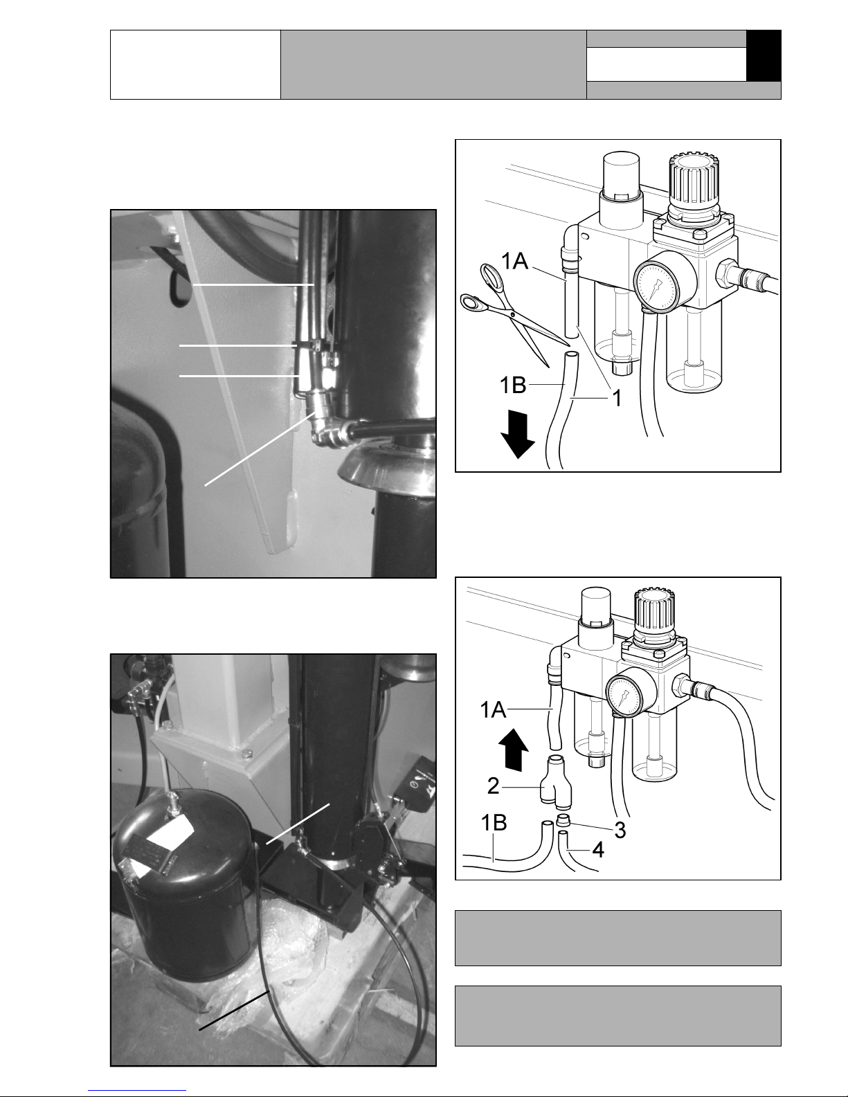
Fig. 15
d - Interpose between the two pipe sections (Fig. 15 pos.
1A - 1B) the “V”union (Fig. 15 pos. 2) (#325181).
Insert the reduction (Fig. 15 pos. 3) (#325054) and
connect the pipe (Fig. 15 pos. 4) coming from the
Plus device control valve to the “V” union (Fig. 15
pos. 2).
c - Cut off the pipe (Fig. 14 pos. 1) as shown in Fig. 14.
Fig. 14
7.3 Pneumatic connection
a - Fix with a clamp (Fig. 12 pos. 4) the union (Fig. 12
pos. 1) on the lateral duct (Fig. 12 pos. 3), exploiting
the black pipe (Fig. 12 pos. 2) that comes out from
it.
Fig. 12
b - In case of connection with tubeless inflation ma-
chine, it is advisable to introduce the black pipe (Fig.
13 pos. 1) through the hole placed on the tank support (Fig. 13 pos. 1).
Fig. 13
1
3
4
2
1
2
Page 11

7700-M002-3
GB
ASSEMBLING AND USE
INSTRUCTIONS
Page 11 of 22
PLUS91S - PLUS91N
PLUS91SE - PLUS91SA - G800A69
DO NOT USE THE BEAD LIFTING DEVICE FOR
BEAD BREAKING TYRES.
8.0 USE OF THE DEVICE
8.1 Work environment condition
The characteristics of the work environment of the fitting must be kept within the limits prescribed for the
tyre demounting machine the fitting is installed on (see
the manual concerning the tyre demounting machine).
8.2 Precaution measures during the assembly and the disassembly of tyres
A - Before carrying out the assembly of the tyres follow
these safety rules:
ALWAYS UTILIZE RIMS AND TYRES
THAT ARE DRY AND IN GOOD STATE;
IN PARTICOLAR, IF REQUIRED
CLEAN THE RIMS AFTER HAVING
REMOVED ALL THE OLD BALANCE
WEIGHTS (INCLUDED THE ADHESIVE WEIGHTS ON THE INNER SIDE)
AND CHECK THAT NEITHER THE
BEAD AND THE TREAD OF THE TYRE
ARE DAMAGED.
LUBRICATE PLENTIFULLY THE CONTACT SURFACE OF THE RIM AND
THE TYRE BEADS USING A LUBRICANT SPECIAL FOR TYRES (NOT
CONTAINING WATER, HYDROCARBONS AND SILICONE).
REPLACE THE VALVE OF THE RIM
WITH A NEW ONE, OR, IN CASE OF
METAL VALVES, REPLACE THE
GROMMET.
ALWAYS CHECK THAT TYRE AND
RIM HAVE THE CORRECT DIMENSIONS FOR THEIR COUPLING; IF
NOT, DO NOT ASSEMBLE THEM.
B - Before carrying out the disassembling of the tyres
follow these safety rules:
DEFLATE THE TYRE COMPLETELY.
Fig. 16
8.3 Control unit
It consists of a handle control (Fig. 16 pos. 1) placed on
the device. Using this handle control it’s possible to control the vertical shifting of the pressing roll (Fig. 1-2-3-4
pos. 4) and the rotary bead depressing unit (Fig. 1-2-34 pos. 1). Lift the lever (Fig. 16 pos. 2) to control the
shifting upwards; lower the lever (Fig. 16 pos. 2) to con-
trol the shifting downwards. The arms positioning of
the device in correspondence of the tyre is completely
manual-operated.
8.4 Using the lift
Make sure the locking hook (Fig. 17 pos. 1) is positioned according to Fig. 17 indications and lock Plus
device to rest position.
Fig. 17
Page 12

7700-M002-3
GB
ASSEMBLING AND USE
INSTRUCTIONS
Page 12 of 22
PLUS91S - PLUS91N
PLUS91SE - PLUS91SA - G800A69
2 - Position the wheel on the chuck.
3 - Lower the control unit lever in order to lower the lift-
ing device.
4 - Carry out all the tyre assembly and disassembly op-
eration, loose the chuck wheel.
5 - To raise the lifting device, lift the control unit lever
again.
6 - Place the wheel onto the lifting device.
7 - Lower again the control unit lever (Fig. 20 pos. 1) in
order to let the lifting device move down (use a hand
to follow its descent) (see Fig. 20).
KEEP A HAND ON THE WHEEL
DURING ALL LIFT RISING AND
DESCENT PHASES TO ENSURE
THAT THE WHEEL CANNOT
FALL FROM THE LIFTING DEVICE DUE TO IMBALANCES.
1 - After the wheel has been placed onto the lifting de-
vice (Fig. 18 pos. 1), lift the control unit lever (Fig.
18 pos. 2) and move the wheel upwards, until it can
be placed onto the mandrel (use a hand to follow its
movement) (see Fig. 19).
Fig. 18
Fig. 20
Fig. 19
Page 13
7700-M002-3
GB
ASSEMBLING AND USE
INSTRUCTIONS
Page 13 of 22
PLUS91S - PLUS91N
PLUS91SE - PLUS91SA - G800A69
8.5 Rim clamping with tyre depressed on
self-centering chucks
If it’s required to act on a depressed tyre it’s possible to
clamp the rim (Fig. 21 pos. 2) into the jaws (Fig. 21
pos. 3) through the vertical thrust of the rotary bead
depressing unit (Fig. 21 pos. 1) (after the application of
the supplied cone) placing it as shown in Fig. 21.
Fig. 21
Clamp the chuck on the rim by using the appropriate
pedal control.
Extraction of the first bead
a - Place the roll of the rotary bead depressing unit (Fig.
23 pos. 1) as shown in figure (not far from the tool
(Fig. 23 pos. 2)). Lower the tyre by using the bead
depressing roll (Fig. 23 pos. 1) (lowering the lever
on the control unit (Fig. 16 pos. A)), until an easy
positioning of the head (Fig. 23 pos. 2) is allowed.
After that lock the head.
8.6 Demounting tyres
PLUS91SE - PLUS91SA DEVICE
Make sure the locking hook (Fig. 22 pos. 1) is positioned according to Fig. 22 indications, in order to
release the cylinder (Fig. 22 pos. 2) from the lifting
device (Fig. 22 pos. 3).
Fig. 22
Page 14

7700-M002-3
GB
ASSEMBLING AND USE
INSTRUCTIONS
Page 14 of 22
PLUS91S - PLUS91N
PLUS91SE - PLUS91SA - G800A69
Fig. 26
d - Place the rotary bead depressing unit (Fig. 25 pos.
1) again at about 120° from the machine-head axis
(as in figure) and lower the tyre positioning the lever
(Fig. 25 pos. A) of the control unit downwards, until
the tyre bead is placed in correspondence of the rim
groove.
e - Load the bead of the tyre by using the appropriate
lever (Fig. 25 pos. 3) on the head (Fig. 25 pos. 2).
Fig. 25
f - Lift the Device plus and close it to its rest position as
shown in figure (Fig. 26 pos. 1).
g - Carry out the extraction of the first bead by rotating
clockwise the chuck (Fig. 26 pos. 2).
b - Insert the bead lifting lever (Fig. 24 pos. 2) between
the tyre (Fig. 24 pos. 4) and the head (Fig. 24 pos. 3).
c - Lift the roll of the rotary bead depressing unit (Fig.
24 pos. 1) of the Plus device lifting the lever (Fig. 24
pos. A).
Fig. 23
Fig. 24
Page 15

7700-M002-3
GB
ASSEMBLING AND USE
INSTRUCTIONS
Page 15 of 22
PLUS91S - PLUS91N
PLUS91SE - PLUS91SA - G800A69
Extraction of the second bead
h - Turn the bead lifting roll (Fig. 27 pos. 1) from its
position until it is placed between the plate of the
chuck and the tyre, at about 1 cm from the lower
external edge of the rim.
i - Lift the tyre by using the bead lifting roll (Fig. 27
pos. 3) by lifting the control unit lever (Fig. 27 pos.
A) upwards.
l - Load the second bead on the head by using the ap-
propriate lever (Fig. 27 pos. 4).
m - Turn the chuck clockwise (Fig. 27 pos. 2) and ex-
tract the tyre from the rim.
Fig. 27
8.6.1 Demounting second bead through
bead lifting roll
To demount the lower bead, it’s possible to use as an
alternative the bead lifting roll. Move the tool drawing it
away from the working area.
a - Lift the roll and the tyre placed in corrispondence of
the rim groove through the hand control.
b - Then, let the roll advance through the hand control
so that it can place itself between the rim groove and
the lower bead.
c - Then rotate and complete the demounting bead.
8.7 Mounting tyres
a - Assemble the first bead on the rim. For this opera-
tion the utilizing of the Device.
b - Place the bead lifting roll (Fig. 28 pos. 1) as shown
in figure.
c - Lower the bead lifting roll (Fig. 28 pos. 1), operating
the provided control (Fig. 28 pos. A), until the bead
of the tyre is placed in correspondence of rim groove.
N.B. With some combinations wheel/rim the bead de-
pressing roll, positioned on the rim edge, might start
sliding near the entrainment point. In these cases,
apply the entrainer (Fig. 28 Pos. 2) in front of the
bead depressing roll, pressing the provided release
lever (Fig. 28 Pos. 3) in the empty space between
the rim spokes.
Fig. 28
MAKE SURE THE ENTRAINER HAS
BEEN COMPLETELY INSERTED BETWEEN THE RIM SPOKES, IN A COMPLETELY LOWERED POSITION AS
SHOWN IN FIG. 29.
IF THE ENTRAINER (FIG. 29 POS. 1)
IS PLACED LIKE IN THIS PICTURE,
PUSH THE RELEASE LEVER (FIG. 29
POS. 2) AND LIFT THE ENTRAINER,
SLIDING IT INSIDE THE SLIDE. THEN
PLACE IT IN THE FIRST USEFUL
SPACE AS SHOWED IN THE ABOVE
REPORTED NOTE.
Page 16

7700-M002-3
GB
ASSEMBLING AND USE
INSTRUCTIONS
Page 16 of 22
PLUS91S - PLUS91N
PLUS91SE - PLUS91SA - G800A69
Fig. 31
h - In order to disengage the entrainer (Fig. 32 Pos. 1)
from the working area, lift it from the tyre through
the provided release lever (Fig. 32 Pos. 2) so that it
slides inside its guide to line up with the wedge tool
to reach rest position again.
Fig. 32
f - Terminate the insertion of the second bead by rotat-
ing the chuck clockwise (see Fig. 31).
g - Lift the Device plus through the relevant control (Fig.
31 pos. A) and close it in its rest position (see Fig.
31).
d - Start the clockwise rotation of the chuck (Fig. 30
pos. 1) by using the appropriate pedal control: dur-
ing this operation accompany the bead depressing
roll (Fig. 30 pos. 2) by hand. This operation, that
doesn’t required phisical stress, helps to keep the
correct position of the bead depressing roll on the
tyre.
e - Stop the chuck rotation when the bead depressing
roll (Fig. 30 pos. 2) reaches 9 o’clock position in comparison with the assembly tool.
Fig. 30
Fig. 29
Page 17

7700-M002-3
GB
ASSEMBLING AND USE
INSTRUCTIONS
Page 17 of 22
PLUS91S - PLUS91N
PLUS91SE - PLUS91SA - G800A69
9.0 ROUTINE MAINTENANCE
In order to ensure the correct operation and efficiency of
the fitting it is essential to abide by the instructions for
daily or weekly cleaning and periodic routine maintenance described in the ROUTINE MAINTENANCE section of the MANUAL OF USE AND MAINTENANCE of
the the tyre changer on which the fitting is fitted.
BEFORE ANY MAINTENANCE INTERVENTION ENSURE THAT THERE ARE NO WHEEL CLAMPED ON
THE CHCK AND THAT THE ELECTRIC AND PNEUMATIC POWER SUPPLY TO THE MACHINE IS CUT.
THE MANUFACTURER DOES NOT
ACCEPT RESPONSIBILITY FOR
ANY DAMAGE RESULTING FROM
THE FAILURE TO OBSERVE THE
ABOVE INSTRUCTIONS, AND
SAID FAILURE COULD INVALIDATE THE GUARANTEE/WARRANTY!
10.0 TROUBLESHOOTING TABLE
Problem
Possible cause
Remedy
When the lever is pressed there is
no movement.
1. Lack of power supply.
2. The supply hoses are wrongly connected.
3. The control valve is faulty.
1. Check the power supply.
2. Check the connection of the hoses.
3. Call for technical assistance.
When the lever is pressed the movement is only in one direction.
The control valve is faulty. Call for technical assistance.
11.0 TECHNICAL DATA
Rim width: .......................................................... 15”
Rim diameter: ................................. min. 8” max 30”
Force on roller: .................................... 4000 N (8 bar)
Operating pressure: ..................................... 8-10 bar
11.1 Weight
PLUS91S DEVICE.................................... max 50 Kg
PLUS91N DEVICE ................................... max 40 Kg
PLUS91SE DEVICE ................................. max 40 Kg
PLUS91SA DEVICE ................................. max 40 Kg
G800A69 LIFTING DEVICE ..................... max 10 Kg
Page 18

7700-M002-3
GB
ASSEMBLING AND USE
INSTRUCTIONS
Page 18 of 22
PLUS91S - PLUS91N
PLUS91SE - PLUS91SA - G800A69
11.2 Dimensions
PLUS91S DEVICE
PLUS91N DEVICE
Fig. 34
Fig. 33
Page 19

7700-M002-3
GB
ASSEMBLING AND USE
INSTRUCTIONS
Page 19 of 22
PLUS91S - PLUS91N
PLUS91SE - PLUS91SA - G800A69
PLUS91SE DEVICE - G800A69
Fig. 35
PLUS91SA DEVICE - G800A69
Fig. 36
Page 20

7700-M002-3
GB
ASSEMBLING AND USE
INSTRUCTIONS
Page 20 of 22
PLUS91S - PLUS91N
PLUS91SE - PLUS91SA - G800A69
12.0 STORING
If machine storing is for long periods, disconnect the
main power supply and take measures to protect the
machine from dust build-up. Lubricate parts that could
be damaged from drying out.
13.0 SCRAPPING
When the decision is taken not to make further use of
the fitting, it is advisable to make it inoperative by removing the connection pressure hoses.
The fitting is to be considered as special waste and
should be dismantled into homogeneous parts.
Dispose of it in accordance with current legislation.
14.0 FUNCTIONAL DIAGRAMS
Here follows a list of the machine functional diagrams.
Page 21

Pag. 21 di 22
PLUS91S - PLUS91N
PLUS91SE - PLUS91SA - G800A69
7700-M002-3
LISTA DEI COMPONENTI - LIST OF COMPONENTS - TEILELISTE
LISTE DES PIECES DETACHEES - LISTA DE PIEZAS
SCHEMA PNEUMATICO
PNEUMATIC DIAGRAM
PNEUMATISCHER SCHEMA
SCHEMA PNEUMATIQUE
ESQUEMA NEUMÁTICO
Tavola A - Rev. 0
Page 22

Pag. 22 di 22
PLUS91S - PLUS91N
PLUS91SE - PLUS91SA - G800A69
N° Cod. Description
1 317006 Tuyau 6x4 noir
2 325181 Raccord à V8
3 325054 Reduction 6-8
4 325224 Raccord à L D.6
7700-M002-3
Raccordo a L D.6 D.6 L union Verbindung L D.6 Enlace a L D.6
Riduzione fissa 6-8 6-8 reduction Reduktion 6-8 Reducción 6-8
Raccordo a V8 V8 union V-Verbindung 8 Enlace a V8
Tubo 6x4 nero 6x4 black pipe Schlauch 6x4 schwarz Tubo 6x4 negro
Descrizione Description Beschreibung Descripcion
LISTA DEI COMPONENTI - LIST OF COMPONENTS - TEILELISTE
LISTE DES PIECES DETACHEES - LISTA DE PIEZAS
SCHEMA PNEUMATICO
PNEUMATIC DIAGRAM
PNEUMATISCHER SCHEMA
SCHEMA PNEUMATIQUE
ESQUEMA NEUMÁTICO
Tavola A - Rev. 0
Page 23

15.0 LISTA DEI COMPONENTI
15.0 LIST OF COMPONENTS
15.0 TEILELISTE
15.0 LISTE DES PIECES DETACHEES
15.0 LISTA DE PIEZAS
GLI ESPLOSI SERVONO SOLO PER L’IDENTIFICAZIONE DELLE PARTI DA SOSTITUIRE.
LA SOSTITUZIONE DEVE ESSERE EFFETTUATA DA PERSONALE PROFESSIONALMENTE QUALIFICATO.
THE DIAGRAMS SERVE ONLY FOR THE IDENTIFICATION OF PARTS TO BE REPLACED.
THE REPLACEMENT MUST BE CARRIED OUT PROFESSIONALLY QUALIFIED PERSONNEL.
DIE ZEICHNUNGEN DIENEN NUR ZUR IDENTIFIZIERUNG DER ERSATZTEILE. DIE ERSETZUNG MUß DURCH QUALIFIZIERTES PERSONAL ERFOLGEN.
LES DESSINS NE SERVENT QU’À L’IDENTIFICATION DES PIÈCES À REMPLACER.
LE REMPLACEMENT DOIT ÊTRE EFFECTUÉ PAR UN PERSONNE PROFESSIONNELLEMENT QUALIFIÉ.
LOS DIBUJOS EN DESPIECE SIRVEN ÚNICAMENTE PARA IDENTIFICAR LAS PIEZAS
QUE DEBEN SUSTITUIRSE. LA SUSTITUCIÓN DE PIEZAS DEBE EFECTUARLA EXCLUSIVAMENTE PERSONAL PROFESIONALMENTE CUALIFICADO.
I
GB
D
F
E
• Per eventuali chiarimenti interpellare il più vicino rivenditore.
• For any further information please contact your local dealer.
• Für Rückfragen wenden Sie sich bitte an den nächsten Wiederverkäufer.
• Pour tout renseignement complémentaire s’adresser au revendeur le plus proche.
• En caso de dudas, para eventuales aclaraciones, póngase en contacto con el distribudor más próximo.
7700-R002-4
7700-R002-4 - Rev. n. 4 (09/2011)
PLUS91S
PLUS91N
PLUS91SE
PLUS91SA
G800A69
Page 24

Pag. 1 di 25
PLUS91S - PLUS91N
PLUS91SE - PLUS91SA - G800A69
BRACCIO STALLONATORE
BEAD BREAKER ARM
ABRÜCKARM
BRAS IMPRIMÉ
BRAZO DESTALONADOR
GRUPPO CILINDRO ASSEMBLATO
ASSEMBLED CYLINDER UNIT
ZUSAMMENGESETZER ZYLINDERSATZ
GROUPE CYLINDRE ASSEMBLÉ
GRUPO CILINDRO ENSEMBLADO
Tavola N°3 - Rev. 1 - PLUS91SE...…..…8
SOMMARIO-SUMMARY-INHALT
SOMMAIRE-SUMARIO
Tavola N°2 - Rev. 1 - PLUS91N……...….4
Tavola N°1 - Rev. 0 - PLUS91S……....…2
Tavola N°9 - Rev. 0 - 770790420..…….22
SUPPORTO RUOTA
WHEEL SUPPORT
REIFENHALTERUNG
SUPPORT ROUE
SOPORTE RUEDA
VALVOLA COMANDO CILINDRI
CYLINDERS CONTROL VALVE
VENTIL STEUERUNG ZYLINDEREN
VANNE COMMANDE CYLINDRES
VÁLVULA MANDO CILINDROS
Tavola N°6 - Rev. 0 - 770090060……...16
DISPOSITIVO PLUS91S
PLUS91S DEVICE
PLUS91S VORRICHTUNG
DISPOSITIF PLUS91S
DISPOSITIVO PLUS91S
GRUPPO CILINDRO ASSEMBLATO
ASSEMBLED CYLINDER UNIT
ZUSAMMENGESETZER ZYLINDERSATZ
GROUPE CYLINDRE ASSEMBLÉ
GRUPO CILINDRO ENSEMBLADO
DISPOSITIVO PLUS91N
PLUS91N DEVICE
PLUS91N VORRICHTUNG
DISPOSITIF PLUS91N
DISPOSITIVO PLUS91N
Tavola N°7 - Rev. 0 - 770090090….…..18
DISPOSITIVO PLUS91SE
PLUS91SE DEVICE
PLUS91SE VORRICHTUNG
DISPOSITIF PLUS91SE
DISPOSITIVO PLUS91SE
Tavola N°8 - Rev. 0 - 770090050….…..20
Tavola N°5 - Rev. 0 - 770090040…..….14 Tavola N°10 - Rev. 0 - PLUS91SA….….24
GRUPPO CILINDRO ASSEMBLATO
ASSEMBLED CYLINDER UNIT
ZUSAMMENGESETZER ZYLINDERSATZ
GROUPE CYLINDRE ASSEMBLÉ
GRUPO CILINDRO ENSEMBLADO
LISTA DEI COMPONENTI
LIST OF COMPONENTS
TEILELISTE
LISTE DES PIECES DETACHEES
LISTA DE PIEZAS
7700-R002-4
DISPOSITIVO PLUS91SA
PLUS91SA DEVICE
PLUS91SA VORRICHTUNG
DISPOSITIF PLUS91SA
DISPOSITIVO PLUS91SA
Tavola N°4 - Rev. 0 - G800A69..…..…..12
Page 25

Pag. 2 di 25
PLUS91S - PLUS91N
PLUS91SE - PLUS91SA - G800A69
7700-R002-4
DISPOSITIVO PLUS91S
PLUS91S DEVICE
PLUS91S VORRICHTUNG
DISPOSITIF PLUS91S
DISPOSITIVO PLUS91S
LISTA DEI COMPONENTI - LIST OF COMPONENTS - TEILELISTE
LISTE DES PIECES DETACHEES - LISTA DE PIEZAS
Tavola N°1 - Rev. 0 PLUS91S
Page 26
Pag. 4 di 25
PLUS91S - PLUS91N
PLUS91SE - PLUS91SA - G800A69
7700-R002-4
LISTA DEI COMPONENTI - LIST OF COMPONENTS - TEILELISTE
LISTE DES PIECES DETACHEES - LISTA DE PIEZAS
DISPOSITIVO PLUS91N
PLUS91N DEVICE
PLUS91N VORRICHTUNG
DISPOSITIF PLUS91N
DISPOSITIVO PLUS91N
Tavola N°2 - Rev. 1 PLUS91N
Page 27

Pag. 8 di 25
PLUS91S - PLUS91N
PLUS91SE - PLUS91SA - G800A69
7700-R002-4
LISTA DEI COMPONENTI - LIST OF COMPONENTS - TEILELISTE
LISTE DES PIECES DETACHEES - LISTA DE PIEZAS
DISPOSITIVO PLUS91SE
PLUS91SE DEVICE
PLUS91SE VORRICHTUNG
DISPOSITIF PLUS91SE
DISPOSITIVO PLUS91SE
Tavola N°3 - Rev. 1 PLUS91SE
Page 28

Pag. 12 di 25
PLUS91S - PLUS91N
PLUS91SE - PLUS91SA - G800A69
7700-R002-4
LISTA DEI COMPONENTI - LIST OF COMPONENTS - TEILELISTE
LISTE DES PIECES DETACHEES - LISTA DE PIEZAS
SUPPORTO RUOTA
WHEEL SUPPORT
REIFENHALTERUNG
SUPPORT ROUE
SOPORTE RUEDA
Tavola N°4 - Rev. 0 G800A69
Page 29

Pag. 14 di 25
PLUS91S - PLUS91N
PLUS91SE - PLUS91SA - G800A69
7700-R002-4
LISTA DEI COMPONENTI - LIST OF COMPONENTS - TEILELISTE
LISTE DES PIECES DETACHEES - LISTA DE PIEZAS
GRUPPO CILINDRO ASSEMBLATO
ASSEMBLED CYLINDER UNIT
ZUSAMMENGESETZER ZYLINDERSATZ
GROUPE CYLINDRE ASSEMBLÉ
GRUPO CILINDRO ENSEMBLADO
Tavola N°5 - Rev. 0 770090040
Page 30

Pag. 16 di 25
PLUS91S - PLUS91N
PLUS91SE - PLUS91SA - G800A69
7700-R002-4
LISTA DEI COMPONENTI - LIST OF COMPONENTS - TEILELISTE
LISTE DES PIECES DETACHEES - LISTA DE PIEZAS
GRUPPO CILINDRO ASSEMBLATO
ASSEMBLED CYLINDER UNIT
ZUSAMMENGESETZER ZYLINDERSATZ
GROUPE CYLINDRE ASSEMBLÉ
GRUPO CILINDRO ENSEMBLADO
Tavola N°6 - Rev. 0 770090060
Page 31

Pag. 18 di 25
PLUS91S - PLUS91N
PLUS91SE - PLUS91SA - G800A69
7700-R002-4
LISTA DEI COMPONENTI - LIST OF COMPONENTS - TEILELISTE
LISTE DES PIECES DETACHEES - LISTA DE PIEZAS
GRUPPO CILINDRO ASSEMBLATO
ASSEMBLED CYLINDER UNIT
ZUSAMMENGESETZER ZYLINDERSATZ
GROUPE CYLINDRE ASSEMBLÉ
GRUPO CILINDRO ENSEMBLADO
Tavola N°7 - Rev. 0 770090090
Page 32

Pag. 20 di 25
PLUS91S - PLUS91N
PLUS91SE - PLUS91SA - G800A69
7700-R002-4
LISTA DEI COMPONENTI - LIST OF COMPONENTS - TEILELISTE
LISTE DES PIECES DETACHEES - LISTA DE PIEZAS
BRACCIO STALLONATORE
BEAD BREAKER ARM
ABRÜCKARM
BRAS IMPRIMÉ
BRAZO DESTALONADOR
Tavola N°8 - Rev. 0 770090050
Page 33

Pag. 22 di 25
PLUS91S - PLUS91N
PLUS91SE - PLUS91SA - G800A69
7700-R002-4
LISTA DEI COMPONENTI - LIST OF COMPONENTS - TEILELISTE
LISTE DES PIECES DETACHEES - LISTA DE PIEZAS
VALVOLA COMANDO CILINDRI
CYLINDERS CONTROL VALVE
VENTIL STEUERUNG ZYLINDEREN
VANNE COMMANDE CYLINDRES
VÁLVULA MANDO CILINDROS
Tavola N°9 - Rev. 0 770790420
Page 34

Pag. 24 di 25
PLUS91S - PLUS91N
PLUS91SE - PLUS91SA - G800A69
7700-R002-4
LISTA DEI COMPONENTI - LIST OF COMPONENTS - TEILELISTE
LISTE DES PIECES DETACHEES - LISTA DE PIEZAS
DISPOSITIVO PLUS91SA
PLUS91SA DEVICE
PLUS91SA VORRICHTUNG
DISPOSITIF PLUS91SA
DISPOSITIVO PLUS91SA
Tavola N°10 - Rev. 0 PLUS91SA
 Loading...