

Page 1

INSTRUCTION MANUAL
• For any further information please contact your local dealer or call:
For spare parts drawings refer to the section “ LIST OF COMPONENTS” enclosed to this manual.
GB
TRANSLATION FROM THE
ORIGINAL INSTRUCTIONS
G3.140R
GP3.140R
G3.140RS
GP3.140RS
1297-M007-1_R
1297-M007-1_R
Technical services: RAVAGLIOLI S.p.A. - Via 1° Maggio, 3 - 40037 Pontecchio Marconi - Bologna Italy
Phone (+39) 051 6781511 - Telex 510697 RAV I - Fax (+39) 051 846349 - e-mail: aftersales@ravaglioli.com
- Rev. n. 1 (02/2015)
Page 2

GB
Page 2 of 60
INSTRUCTION, USE AND
MAINTENANCE MANUAL
SUMMARY
SYMBOLS USED IN THE MANUAL AND ON
THE MACHINE __________________________ 5
1.0 GENERAL INTRODUCTION _________ 7
1.1 Introduction ___________________________7
2.0 INTENDED USE ____________________ 7
2.1 Staff training __________________________ 7
3.0 SAFETY DEVICES __________________ 8
3.1 Residual risks _________________________ 8
4.0 GENERAL SAFETY RULES _________ 8
5.0 PACKING AND MOBILIZATION FOR
TRANSPORT _______________________ 9
6.0 UNPACKING _______________________ 10
7.0 MOBILIZATION ____________________ 10
8.0 WORKING ENVIRONMENT
CONDITIONS ______________________ 10
8.1 Working area ________________________ 11
8.2 Lighting _____________________________ 11
9.0 MACHINE ASSEMBLY _____________ 11
9.1 Anchoring system ___________________ 11
9.2 Fixtures contained in the packing ___ 12
9.3 Assembly procedures ________________ 13
9.3.1 Fitting the mandrel on the flange _ 13
9.3.2 Fitting and removal of the
pneumatic mandrel on the
flange ___________________________ 13
9.3.3 Fitting of external data gauge
(standard for G3.140RS -
GP3.140RS versions) (optional for
G3.140R - GP3.140R versions) ___ 15
9.3.4 Fitting of professional external
data gauge (optional)____________ 16
9.3.5 Monitor fitting __________________ 17
9.3.6 Fitting the protection guard _____ 18
10.0 ELECTRICAL CONNECTION _______ 18
10.1 Electrical checks ____________________ 19
11.0 AIR CONNECTIONS _______________ 19
12.0 FITTING THE WHEEL ON THE
MANDREL _________________________ 20
12.1 Fitting of the wheel (G3.140R -
G3.140RS) ___________________________ 20
12.2 Fitting of the wheel (GP3.140R GP3.140RS) _________________________ 21
13.0 CONTROL PANEL _________________ 23
14.0 WHEEL BALANCING ______________ 23
14.1 Switching the machine on and off ___ 23
14.2 Balancing programs setting _________ 24
14.2.1 Programs rapid setting and
measurements through distancediameter caliper arm ____________ 24
14.2.2 Programs setting through
“Measurement being acquired”
screen page _____________________ 27
14.3 Indicative display of points where to
detect measures/to fit weight ________ 28
14.3.1 Weights positioning _____________ 28
14.4 Displaying the active/modifiable
field _________________________________ 28
14.5 Wheel balancing screen page
description __________________________ 29
14.5.1 Balancing mode _________________ 30
14.6 Use of machines with disabled
automatic gauge ____________________ 32
14.6.1 Manual setting of wheel
dimensions ______________________ 32
14.7 Standard balancing programs_______ 32
14.7.1 Static____________________________ 32
14.7.2 Static-1 __________________________ 33
14.7.3 Static-2 __________________________ 33
14.7.4 Dynamic_________________________ 33
14.7.5 ALU-S ___________________________ 33
14.7.6 ALU-S1 __________________________ 34
14.7.7 ALU-S2 __________________________ 34
14.7.8 ALU-1 ____________________________ 34
14.7.9 ALU-2 ____________________________ 34
14.7.10 ALU-3 __________________________ 35
14.7.11 ALU-4 __________________________ 35
14.8 Optional balancing programs _______ 35
14.8.1 ECO-WEIGHT mode ______________ 35
14.8.2 SPLIT mode _____________________ 37
14.8.3 Weights hidden behind spokes
mode ____________________________ 39
14.8.4 Matching mode __________________ 40
14.9 Special balancing programs _________ 43
14.9.1 Pax ______________________________ 43
14.10 Recalculation Function _____________ 43
14.11 Motorbike Mode wheel balancing ___ 44
15.0 USER MENU (OPTIONS AND
CALIBRATION) ____________________ 45
15.1 Options menu ________________________ 45
15.1.1 Lower weight limit ______________ 47
15.1.2 Setting adhesive weight
dimensions and static threshold
percentage ______________________ 47
15.1.3 User management _______________ 48
15.2 Machine calibration _________________ 49
15.2.1 Mandrel “Ø” calibration _________ 49
G3.140R - GP3.140R - G3.140RS - GP3.140RS
RAVAGLIOLI S.p.A.
1297-M007-1_R
Page 3

INSTRUCTION, USE AND
MAINTENANCE MANUAL
GB
Page 3 of 60
15.2.2 Weight measurement sensors calibration ______________________________ 49
15.2.3 Gauge calibration _______________ 50
16.0 ERROR SIGNALS __________________ 54
17.0 ROUTINE MAINTENANCE _________ 55
18.0 TECHNICAL DATA _________________ 56
18.1 Dimensions __________________________ 57
19.0 STORING __________________________ 58
20.0 SCRAPPING _______________________ 58
21.0 REGISTRATION PLATE DATA _____ 58
22.0 FUNCTIONAL DIAGRAMS _________ 58
Table A - Electrical and pneumatic
connection diagram ____________ 59
23.0 LIST OF COMPONENTS
1297-M007-1_R
G3.140R - GP3.140R - G3.140RS - GP3.140RS
RAVAGLIOLI S.p.A.
Page 4

GB
Page 4 of 60
INSTRUCTION, USE AND
MAINTENANCE MANUAL
1
2
3
4
5
6
7
8
9
10
11
11
12
13
14
15
16
17
18
G3.140R - GP3.140R - G3.140RS - GP3.140RS
RAVAGLIOLI S.p.A.
1297-M007-1_R
KEY
1 – Weight holding bridge
2 – Pneumatic mandrel (only for GP3.140R - GP3.140RS models)
3 – Distance-diameter caliper
4 – Threaded mandrel (only for G3.140R - G3.140RS models)
5 – Protection guard
6 – Foot brake (only for G3.140R - G3.140RS models) / pneumatic mandrel open-close pedal (only for
GP3.140R - GP3.140RS models)
7 – Main switch
8 – External data gauge (standard for G3.140RS - GP3.140RS models ) (optional for G3.140R - GP3.140R
models)
9 – Fixed laser unit + led light (standard for G3.140RS - GP3.140RS models)
10 – Monitor
11 – Pusher ring
12 – Rapid ring nut (only for G3.140R - G3.140RS models)
13 – Locking sleeve (only for GP3.140R - GP3.140RS models)
14 – Cones
15 – Professional external data gauge (optional)
16 – Grippers for weight fitting
17 – Lateral guard
18 – Push-button panel with 7 keys
Fig. 1 - G3.140R - GP3.140R - G3.140RS - GP3.140RS
Page 5

INSTRUCTION, USE AND
MAINTENANCE MANUAL
GB
Page 5 of 60
SYMBOLS USED IN THE MANUAL AND ON THE MACHINE
Symbols Description
2167000
Read instruction manual.
FORBIDDEN!
Wear work gloves.
Wear work shoes.
2167000
Wear safety earcaps.
99990758
Shock hazard.
Caution: hanging loads.
Mandatory. Operations or jobs to
be performed compulsorily.
Danger! Be particularly careful.
Symbols Description
Move with fork lift truck or pallet
truck.
Lift from above.
1541000
General danger.
Wear safety goggles.
Technical assistance necessary.
Do not perform any intervention.
Warning. Be particularly careful
(possible material damages).
Note. Indication and/or useful
information.
Attention: never lift the machine
by means of the mandrel.
99990114
Arrow plate.
999912940
1297-M007-1_R
G3.140R - GP3.140R - G3.140RS - GP3.140RS
RAVAGLIOLI S.p.A.
Page 6

GB
Page 6 of 60
INSTRUCTION, USE AND
MAINTENANCE MANUAL
99990114
99990758
999912940
999914160
999914170
999910050
•
*
999916310
999920190
999920540
INFORMATION PLATE LOCATION TABLE
IF ONE OR MORE PLATES DISAPPEARS FROM THE MACHINE OR BECOMES DIFFICULT
TO READ, IT MUST BE REPLACED. QUOTE THE CODE NUMBER WHEN REORDERING.
99990114
99990758
999910050
999912940
999914160
999914170
999916310
999920190
999920540
•
*
Arrow plate
Electricity danger plate
Protection device use plate
Lifting plate
Voltage 230V 50/60 Hz 1 Ph plate
Voltage 115V 50/60 Hz 1 Ph plate
Skip label
New G3 logo plate
Laser point danger plate
Serial number plate
Manufacturer trademark nameplate
Code numbers of plates
G3.140R - GP3.140R - G3.140RS - GP3.140RS
RAVAGLIOLI S.p.A.
1297-M007-1_R
Page 7

INSTRUCTION, USE AND
MAINTENANCE MANUAL
GB
Page 7 of 60
SOME OF THE PICTURES PRESENT IN THIS MANUAL HAVE
BEEN OBTAINED FROM PICTURES
OF PROTOTYPES, THEREFORE
THE STANDARD PRODUCTION
MACHINES AND ACCESSORIES
CAN BE DIFFERENT IN SOME
COMPONENTS.
1.0 GENERAL INTRODUCTION
This manual is an integral part of the product and
must be retained for the whole operating life of the
machine.
Carefully study the warnings and instructions contained in this manual. It contains important instructions regarding FUNCTIONING, SAFE USE and
MAINTENANCE.
KEEP THE MANUAL IN A KNOWN,
EASILY ACCESSIBLE PLACE FOR
ALL ACCESSORY OPERATORS
TO CONSULT IT WHENEVER IN
DOUBT.
THE MANUFACTURER DISCLAIMS
ALL RESPONSIBILITY FOR ANY
DAMAGE OCCURRED WHEN THE
INDICATIONS GIVEN IN THIS
MANUAL ARE NOT RESPECTED:
AS A MATTER OF FACT, THE NONCOMPLIANCE WITH SUCH INDICATIONS MIGHT LEAD TO EVEN
SERIOUS DANGERS.
1.1 Introduction
Thank you for preferring this wheel balancer. We feel
sure you will not regret your decision.
This machine has been designed for use in professional workshops and stands out for its reliability
and easy, safe and rapid operation. With just a small
degree of maintenance and care, this wheel balancer
will give you many years of trouble-free service and
lots of satisfaction.
2.0 INTENDED USE
The machines models G3.140R - GP3.140R G3.140RS - GP3.140RS, and relative versions,
are wheel balancers for car and light transport,
projected to be used exclusively to cancel out, or at
least reduce to acceptable limits the vibrations of the
wheels, by fitting counterweights of suitable size and
in specific positions to the same wheels that are not
correctly balanced.
DANGER: THIS MACHINE MUST
BE USED STRICTLY FOR THE
INTENDED PURPOSE IT WAS DESIGNED FOR (AS INDICATED IN
THIS MANUAL).
THE MANUFACTURER CANNOT
BE HELD RESPONSIBLE FOR ANY
DAMAGE CAUSED BY IMPROPER,
ERRONEOUS, OR UNACCEPTABLE
USE.
AN INTENSIVE USE OF THE EQUIPMENT IN INDUSTRIAL ENVIRONMENT IS NOT RECOMMENDED.
2.1 Staff training
The machine may be operated only by suitably
trained and authorized personnel.
Given the complexity of the operations necessary to
manage the machine and to carry out the operations
safely and efficiently, the personnel must be trained
in such a way that they learn all the information
necessary to operate the machine as intended by the
manufacturer.
A CAREFUL READING OF THIS
INSTRUCTION MANUAL FOR
USE AND MAINTENANCE AND A
SHORT PERIOD OF TRAINING
WITH SKILLED PERSONNEL CAN
BE AN ENOUGH PREVENTIVE
PREPARATION.
1297-M007-1_R
G3.140R - GP3.140R - G3.140RS - GP3.140RS
RAVAGLIOLI S.p.A.
Page 8

GB
Page 8 of 60
INSTRUCTION, USE AND
MAINTENANCE MANUAL
3.0 SAFETY DEVICES
• Master switch positioned on the rear of the machine
Its function is to disconnect machine electric supply.
• Protection guard
Its function is to protect the operator from possible
projections of materials on the wheel during its spin.
Wheel spinning is normally prevented if the wheel
protection guard is raised (open). When the
protection guard is open, this interrupts the circuit that triggers the motor and automatic start
is prevented, including in the case of an error.
Press stop key to stop wheel rotation in
emergency conditions.
3.1 Residual risks
The machine was subjected to a complete analysis of
risks according to reference standard EN ISO 12100.
Risks are as reduced as possible in relation with technology and product functionality.
Possible residual risks have been emphasized through
pictorial representations and warnings which placing is
indicated in “ PLATE POSITIONING TABLE” at page 6.
4.0 GENERAL SAFETY RULES
• Any tampering with or modification to the machine
not previously authorized by the manufacturer exempts the latter from all responsibility for damage
caused by or derived from said actions.
• Removing of or tampering with the safety devices or
with the warning signals placed on the machine leads
to serious dangers and represents a transgression of
European safety rules.
• Use of the machine is only permitted in places free
from explosion or fire hazard and in dry places
under cover.
• Original spare parts and accessories should be used.
THE MANUFACTURER DENIES
ANY RESPONSIBILITY IN CASE
OF DAMAGES CAUSED BY UNAUTHORIZED MODIFICATIONS OR
BY THE USE OF NON ORIGINAL
COMPONENTS OR EQUIPMENT.
• Installation must be conducted only by qualified
personnel exactly according to the instructions that
are given below.
• Ensure that there are no dangerous situations during the machine operating manoeuvres. Immediately
stop the machine if it miss-functions and contact the
assistance service of an authorized dealer.
• In emergency situations and before carrying out any
maintenance or repairs, disconnect all supplies to
the machine by using the main switch, placed on the
machine itself, and unplugging the power supply.
• The machine electrical supply system must be
equipped with an appropriate earthing, to which
the yellow-green machine protection wire must be
connected.
• Ensure that the work area around the machine is free
of potentially dangerous objects and that there is no
oil since this could damage the tyre. Oil on the floor
is also a potential danger for the operator.
• UNDER NO CIRCUMSTANCES must the machine be
used to spin anything but vehicle wheels. Bad locking
can cause rotating parts to come loose, with potential
damage to the machine and anything in the vicinity
and injury to the operator.
G3.140R - GP3.140R - G3.140RS - GP3.140RS
RAVAGLIOLI S.p.A.
1297-M007-1_R
Page 9

INSTRUCTION, USE AND
MAINTENANCE MANUAL
GB
Page 9 of 60
Fig. 2
5.0 PACKING AND MOBILIZATION
FOR TRANSPORT
HAVE THE MACHINE HANDLED BY SKILLED
PERSONNEL ONLY.
THE LIFTING EQUIPMENT MUST WITHSTAND
A MINIMUM RATED LOAD EQUAL TO THE
WEIGHT OF THE PACKED MACHINE (SEE
PARAGRAPH “TECHNICAL SPECIFICATIONS”).
The machine is packed completely assembled. The
machine is inside a carton box which size is mm
1040x950x1090.
Movement must be by pallet-lift or fork-lift trolley.
The fork lifting points are indicated on the packing.
OPERATORS MUST WEAR SUITABLE WORK CLOTHES, PROTECTIVE GLASSES AND GLOVES,
AGAINST THE DANGER FROM
THE SPRAYING OF DANGEROUS
DUST, AND POSSIBLY LOWER
BACK SUPPORTS FOR THE LIFTING OF HEAVY PARTS. DANGLING
OBJECTS LIKE BRACELETS MUST
NOT BE WORN, AND LONG HAIR
MUST BE TIED UP. FOOTWEAR
SHOULD BE ADEQUATE FOR THE
TYPE OF OPERATIONS TO BE CARRIED OUT.
• The machine handles and operating grips must be
kept clean and free from oil.
• The workshop must be kept clean and dry. Make sure
that the working premises are properly lit.
The machine can be operated by a single operator.
Unauthorized personnel must remain outside the
working area, as shown in Fig. 3.
Avoid any hazardous situations. Do not use airoperated or electrical equipment when the shop is
damp or the floor slippery and do not expose such
tools to atmospheric agents.
• When operating and servicing this machine, carefully
follow all applicable safety and accident-prevention
precautions.
The machine must not be operated by professionally
unskilled persons.
WHEN USING THE MODELS WITH
WHEEL PNEUMATIC CLAMPING,
DURING MANDREL OPENING/
CLOSING OPERATIONS, BE EXTREMELY CAREFUL AND KEEP
YOUR HANDS OR OTHER PARTS
OF YOUR BODY AWAY FROM THE
MOVING MANDREL.
1297-M007-1_R
G3.140R - GP3.140R - G3.140RS - GP3.140RS
RAVAGLIOLI S.p.A.
Page 10

GB
Page 10 of 60
INSTRUCTION, USE AND
MAINTENANCE MANUAL
7.0 MOBILIZATION
THE LIFTING EQUIPMENT MUST WITHSTAND
A MINIMUM RATED LOAD EQUAL TO THE
WEIGHT OF THE MACHINE (SEE PARAGRAPH
TECHNICAL SPECIFICATIONS). DO NOT ALLOW THE LIFTED MACHINE TO SWING.
NEVER LIFT THE MACHINE BY MEANS OF THE
MANDREL.
If the machine has to be moved from its normal work
post, the movement must be conducted following the
instructions listed below.
• Protect the exposed corners with suitable material
(Pluribol/cardboard).
• Do not use metallic cables for lifting.
• Make sure the electrical supply (and, for GP3.140R
- GP3.140RS models, the pneumatic supply) of the
machine is not connected.
• Place again the machine onto the original pallet with
whom it was delivered.
• Use transpallet or fork-lift for handling.
8.0 WORKING ENVIRONMENT CONDI-
TIONS
The machine must be operated under proper conditions as follows:
• temperature: 0° + 45° C
• relative humidity: 30 - 90% (dew-free)
• atmospheric pressure: 860 - 1060 hPa (mbar).
The use of the machine in ambient conditions other
than those specified above is only allowed after prior
agreement with and approval of the manufacturer.
6.0 UNPACKING
DURING UNPACKING, ALWAYS
WEAR GLOVES TO PREVENT ANY
INJURY CAUSED BY CONTACT
WITH PACKAGING MATERIAL
(NAILS, ETC.).
The cardboard box is supported with plastic strapping.
Cut the strapping with suitable scissors. Use a small
knife to cut along the lateral axis of the box and open
it like a fan.
It is also possible to unnail the cardboard box from
the pallet it is fixed to. After removing the packing, and
in the case of the machine packed fully assembled,
check that the machine is complete and that there is
no visible damage.
If in doubt do not use the machine and refer to professionally qualified personnel (to the seller).
The packing (plastic bags, expanded polystyrene, nails,
screws, timber, etc.) should not be left within reach of
children since it is potentially dangerous. These materials should be deposited in the relevant collection
points if they are pollutants or non biodegradable.
THE BOX CONTAINING THE FIXTURES IS CONTAINED IN THE
WRAPPING. DO NOT THROW IT
AWAY WITH THE PACKING.
G3.140R - GP3.140R - G3.140RS - GP3.140RS
RAVAGLIOLI S.p.A.
1297-M007-1_R
Page 11

INSTRUCTION, USE AND
MAINTENANCE MANUAL
GB
Page 11 of 60
600
600
600
X
b
a
1
X
X
c
8.1 Working area
Fig. 4
a = 306
b = 580
c = 55
USE THE MACHINE INDOORS OR IN A ROOFED
AREA. PLACE OF INSTALLATION MUST BE
DRY, ADEQUATELY LIT AND IN COMPLIANCE
WITH APPLICABLE SAFETY REGULATIONS.
The location of the machine requires a usable space
as indicated in Fig. 3. The positioning of the machine
must be according to the distances shown. From the
control position the operator is able to observe all the
machine and surrounding area. He must prevent unauthorized personnel or objects that could be dangerous
from entering the area.
The machine must be fixed on a flat floor surface,
preferably of cement or tiled. Avoid yielding or irregular surfaces.
The base floor must be able to support the loads transmitted during operation.
This surface must have a strength of at least 500 kg/m².
The depth of the solid floor must be sufficient to guarantee that the anchoring bolts hold.
8.2 Lighting
The machine does not require its own lighting for
normal working operations. However, it must be used
in an adequately lit environment.
In case of poor lighting use lamps having total power
800/1200 Watt.
IF IT IS INSTALLED, EACH TIME
THE ROD OF THE GAUGE IS EXTRACTED FROM ITS HOUSING,
THE LED LIGHT (FIG. 1 REF. 9)
TURNS ON MAKING THE INSIDE
OF THE WHEEL WHERE THE OPERATOR MUST WORK BRIGHTER.
9.0 MACHINE ASSEMBLY
After having freed the various components from the
packing check that they are complete, and that there
are no anomalies, then comply with the following instructions for the assembly of the components making
use of the attached series of illustrations.
9.1 Anchoring system
The packed machine is fixed to a pallet by support feet.
Such feet also fix the machine to the ground through
anchor small blocks as shown in Fig. 4 ref._1.
IN CASE OF WHEEL WEIGHING
MORE THAN 30 KG, IT IS COMPULSORY TO FIX TO THE GROUND
BY MEANS OF SCREW ANCHORS.
The holes in the solid floor must be about 10 cm deep
with a diameter of 8 MA.
The bolts (Fig. 4 ref. 1) must be inserted in the prearranged holes and fully tightened (tightening torque:
about 22 Nm) until reaching the system full seal.
Fig. 3
1297-M007-1_R
G3.140R - GP3.140R - G3.140RS - GP3.140RS
RAVAGLIOLI S.p.A.
Page 12

GB
Page 12 of 60
INSTRUCTION, USE AND
MAINTENANCE MANUAL
1300A004
999072
129571492
GAR111
GAR101
GAR108
129590710
A
Fig. 5
9.2 Fixtures contained in the packing
The packing case contains also the fixtures box.
Check that all the parts listed below are there (see
Fig. 5).
For G3.140R model
Code Description N.
GAR101 Rapid ring nut + pusher ring 1
GAR111 Cones + protection cup 1
129571492 Gauge 1
1300A004 Weight pliers 1
999072 Carriages counterweight 1
For GP3.140R model
Code Description N.
GAR108 Rapid ring nut + pusher ring 1
GAR111 Cones + protection cup 1
129571492 Gauge 1
1300A004 Weight pliers 1
999072 Carriages counterweight 1
For G3.140RS model
Code Description N.
GAR101 Rapid ring nut + pusher ring 1
GAR111 Cones + protection cup 1
129571492 Gauge 1
1300A004 Weight pliers 1
999072 Carriages counterweight 1
129590710 External data gauge 1
For GP3.140RS model
Code Description N.
GAR108 Rapid ring nut + pusher ring 1
GAR111 Cones + protection cup 1
129571492 Gauge 1
1300A004 Weight pliers 1
999072 Carriages counterweight 1
129590710 External data gauge 1
THE GRIP-RING (FIG. 5 REF. A)
MUST BE MOUNTED WITH THE
TEETH OR DISCHARGE SIDE
TOWARDS THE RING-NUT OR
SLEEVE (SEE FIG. 5).
G3.140R - GP3.140R - G3.140RS - GP3.140RS
RAVAGLIOLI S.p.A.
1297-M007-1_R
Page 13

INSTRUCTION, USE AND
MAINTENANCE MANUAL
GB
Page 13 of 60
1
2
Fig. 6
Fig. 7
Fig. 8
9.3 Assembly procedures
9.3.1 Fitting the mandrel on the flange
Only for G3.140R - G3.140RS models
Screw the mandrel with an Allen wrench (Fig. 6 ref. 1)
on the flange (Fig. 6 ref. 2).
9.3.2 Fitting and removal of the pneumatic
mandrel on the flange
Only for GP3.140R - GP3.140RS models
FITTING
1. After making power and air connections switch on
the machine (the pneumatic mandrel always opens
when the machine is switched on). Switch the machine off. Fit the internal mandrel on the flange
and tighten it with the wrench provided (Fig. 7
and Fig. 8).
1297-M007-1_R
G3.140R - GP3.140R - G3.140RS - GP3.140RS
RAVAGLIOLI S.p.A.
Page 14

GB
Page 14 of 60
INSTRUCTION, USE AND
MAINTENANCE MANUAL
2. Press the brake's pedal and, at the same time, tighten
the internal mandrel as far as it will go using the
wrench provided (Fig. 9).
Fig. 9
3. Fit the external mandrel and tighten it manually
(Fig. 10).
Fig. 10
4. Close the pneumatic mandrel by means of the pedal
to access the key socket (Fig.(Fig. 11).
Fig. 11
5. Press the brake pedal and at the same time block
the external mandrel using the wrench supplied
(Fig. 12).
Fig. 12
REMOVAL
• Close the pneumatic mandrel by means of the pedal
to access the key socket (Fig. 11).
• Press the brake pedal and at the same time release
the external mandrel by using the wrench provided
(Fig. 12).
• Remove the external mandrel, open the pneumatic
mandrel by means of the pedal provided and loosen
the internal mandrel using the special wrench
(Fig. 9).
G3.140R - GP3.140R - G3.140RS - GP3.140RS
RAVAGLIOLI S.p.A.
1297-M007-1_R
Page 15

INSTRUCTION, USE AND
MAINTENANCE MANUAL
GB
Page 15 of 60
1
2
3
1
2
2
3
4
5
6
1
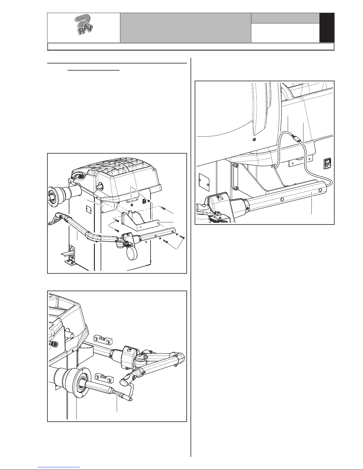
9.3.3 Fitting of external data gauge (standard
for G3.140RS - GP3.140RS versions)
(optional for G3.140R - GP3.140R versions)
1. Unscrew the fastening screws of the equalizer's
support (Fig. 13 ref. 1), being very careful about
holding the same support.
2. Unscrew the 3 screws (Fig. 13 ref. 2) to the gauge
bracket (Fig. 13 ref. 3) and in the special inserts
placed on the rear side of the frame.
Lock the gauge arm (Fig. 13 ref. 4) by screwing
the 2 screws provided (Fig. 13 ref. 5). Lock these
screws with the nuts (Fig. 13 ref. 6) so that the
mandrel and the gauge arm are levelled out (see
Fig. 14).
Fig. 13
3. Also make sure the gauge tip (Fig. 14 ref. 1) is
positioned at the centre of the mandrel.
Fig. 14
4. Connect connector (Fig. 15 ref. 1) of the cable coming from inside the machine to connector (Fig. 15
ref. 2) of the cable coming from the gauge arm. Fit
the section of the cable with the connectors inside
the arm (Fig. 15 ref. 3).
5. Fasten the cable with clamps.
6. Enable the external data gauge and carry out the
device's calibration.
Fig. 15
1297-M007-1_R
G3.140R - GP3.140R - G3.140RS - GP3.140RS
RAVAGLIOLI S.p.A.
Page 16
GB
Page 16 of 60
INSTRUCTION, USE AND
MAINTENANCE MANUAL
1
2
4
5
2
3
6
1
2
3
1
9.3.4 Fitting of professional external data
gauge (optional)
1. Unscrew the fastening screws of the equalizer's
support (Fig. 16 ref. 1), being very careful about
holding the same support.
2. Unscrew the 3 screws (Fig. 16 ref. 2) to the gauge
bracket (Fig. 16 ref. 3) and in the special inserts
placed on the rear side of the frame.
Lock the gauge arm (Fig. 16 ref. 4) by screwing
the 2 screws provided (Fig. 16 ref. 5). Lock these
screws with the nuts (Fig. 16 ref. 6) so that the
mandrel and the gauge arm are levelled out (see
Fig. 17).
Fig. 16
3. Also make sure the gauge tip (Fig. 17 ref. 1) is
positioned at the centre of the mandrel.
Fig. 17
4. Connect connector (Fig. 18 ref. 1) of the cable com-
ing from inside the machine to connector (Fig. 18
ref. 2) of the cable coming from the gauge arm. Fit
the section of the cable with the connectors inside
the arm (Fig. 18 ref. 3).
Fig. 18
5. Fasten the cable with clamps.
6. Enable the external data gauge and carry out the
device's calibration.
G3.140R - GP3.140R - G3.140RS - GP3.140RS
RAVAGLIOLI S.p.A.
1297-M007-1_R
Page 17

INSTRUCTION, USE AND
MAINTENANCE MANUAL
GB
Page 17 of 60
1
90°
3
4
5
2
1
2
3
3
4
4
1
2
3
3
4
4
9.3.5 Monitor fitting
1. Unscrew the nuts (Fig. 19 ref. 1) and the washers
(Fig. 19 ref. 2) from the screws (Fig. 19 ref. 3).
Fit the support tube (Fig. 19 ref. 4) rotated through
90°, paying attention to the monitor and keyboard
cables (Fig. 19 ref. 5) inside it. Then screw the
previously unscrewed nuts and washers again.
Fig. 19
2. Connect the plugs on the power supply sockets and
monitor signal. Connect the wiring of the keyboard.
3. Fix the monitor (Fig. 20 ref. 1) to the support
(Fig. 20 ref. 2) with the screws (Fig. 20 ref. 3)
and the washers (Fig. 20 ref. 4) supplied.
Fig. 20
4. Mount the guard (Fig. 21 ref. 1) to the support
(Fig. 21 ref. 2) with the 6 screws (Fig. 21 ref. 3)
and the washers (Fig. 21 ref. 4) supplied.
Fig. 21
1297-M007-1_R
G3.140R - GP3.140R - G3.140RS - GP3.140RS
RAVAGLIOLI S.p.A.
Page 18

GB
Page 18 of 60
INSTRUCTION, USE AND
MAINTENANCE MANUAL
1
2
3
4
4
Fig. 22
9.3.6 Fitting the protection guard
1. Mount the protection guard (Fig. 22 ref. 1) to the
support (Fig. 22 ref. 2) using the screws (Fig. 22
ref. 3), interposing the Belleville washers (Fig. 22
ref. 4).
2. Tighten the screws (Fig. 22 ref. 3) in order to make
the guard (Fig. 22 ref. 1) lift or lower without
bumping against the limit switch. Carry out the
adjustment so that it's possible to manually guide
the guard both during closing and opening.
DURING GUARD'S ASSEMBLY,
PAY ATTENTION TO THE MICRO
PLACED INSIDE THE MACHINE.
10.0 ELECTRICAL CONNECTION
EVEN THE TINIEST PROCEDURE
OF AN ELECTRICAL NATURE
MUST BE CARRIED OUT BY PROFESSIONALLY QUALIFIED STAFF.
BEFORE CONNECTING THE MACHINE MAKE SURE THAT:
• THE MAIN POWER RATING CORRESPONDS TO THE MACHINE
RATING AS SHOWN ON THE
MACHINE PLATE;
• ALL MAIN POWER COMPONENTS ARE IN GOOD CONDITION;
• THE ELECTRICAL SYSTEM
IS PROPERLY GROUNDED
(GROUND WIRE MUST BE THE
SAME CROSS-SECTION AREA
AS THE LARGEST POWER SUPPLY CABLES OR GREATER);
• MAKE SURE THAT THE ELECTRICAL SYSTEM FEATURES A
CUTOUT WITH DIFFERENTIAL
PROTECTION SET AT 30 mA.
Connect the machine up to the mains by means of the
3-pole plug provided (230 V single-phase) through the
wall socket.
If the plug provided is not suitable for the wall socket,
fit a plug that complies with local and applicable regulations. This operation must be performed by expert
and professional personnel.
FIT A TYPE-APPROVED (AS REPORTED BEFORE) PLUG TO THE
MACHINE CABLE (THE GROUND
WIRE IS YELLOW/GREEN AND
MUST NEVER BE CONNECTED TO
THE PHASE LEADS). MAKE SURE
THAT THE ELECTRICAL SYSTEM
IS COMPATIBLE WITH THE RATED
POWER ABSORPTION SPECIFIED
IN THIS MANUAL AND APT TO
ENSURE THAT VOLTAGE DROP
UNDER FULL LOAD WILL NOT
EXCEED 4% OF RATED VOLTAGE
(10% UPON START-UP).
G3.140R - GP3.140R - G3.140RS - GP3.140RS
RAVAGLIOLI S.p.A.
1297-M007-1_R
Page 19

INSTRUCTION, USE AND
MAINTENANCE MANUAL
GB
Page 19 of 60
1
Fig. 24
FAILURE TO OBSERVE THE ABOVE
INSTRUCTIONS WILL IMMEDIATELY INVALIDATE THE WARRANTY.
10.1 Electrical checks
BEFORE STARTING UP THE
WHEEL-BALANCER, BE SURE TO
BECOME FAMILIAR WITH THE LOCATION AND OPERATION OF ALL
CONTROLS AND CHECK THEIR
PROPER OPERATION (SEE PAR.
“CONTROLS”).
CARRY OUT A DAILY CHECK OF
MAINTAINED-TYPE CONTROLS
CORRECT FUNCTIONING, BEFORE
STARTING MACHINE OPERATION.
Once the plug/socket connection has been made, turn
on the machine using the master switch (Fig. 23
ref. 1).
11.0 AIR CONNECTIONS
Only for GP3.140R - GP3.140RS models
IN CASE OF A CHANCE SUPPLY FAILURE, AND/OR BEFORE
ANY PNEUMATIC CONNECTIONS,
MOVE THE CONTROLS TO THE
NEUTRAL POSITION.
Connect the wheel balancer to the centralised compressed-air system by means of the connection on the
back of the machine (see Fig. 24).
The air system supplying the machine must be able
to supply filtered and de-humidified air at a pressure
between 8 and 10 bar. It must feature an on-off valve
upstream of the machine.
Fig. 23
1297-M007-1_R
G3.140R - GP3.140R - G3.140RS - GP3.140RS
RAVAGLIOLI S.p.A.
Page 20

GB
Page 20 of 60
INSTRUCTION, USE AND
MAINTENANCE MANUAL
1
2
3
4
1
2
1
2
3
4. Fit the protection cap (Fig. 26 ref. 1) in the locknut
(Fig. 26 ref. 2) and fasten against the wheel.
Fig. 25
Fig. 26
Fig. 27
Some aluminium wheels, with very high centring, must
be fitted with the cone outside the wheel.
5. Clean the mandrel (Fig. 27 ref. 1) before fitting
the wheel.
6. Fit the wheel (Fig. 27 ref. 3) with the inside of the
rim towards the wheel balancer, until the wheel is
up against the support flange (Fig. 27 ref. 2).
12.0 FITTING THE WHEEL ON THE
MANDREL
To achieve perfect balancing, the wheel must be carefully and properly fitted on the mandrel. Imperfect
centring will inevitably cause unbalances.
MOST IMPORTANT IS THAT ORIGINAL CONES AND ACCESSORIES
ARE USED MADE SPECIFICALLY
FOR USE ON THE WHEEL BALANCER.
Wheel fitting using the cones provided is illustrated below. For alternative fittings, using optional accessories,
refer to the special instructions provided separately.
12.1 Fitting of the wheel (G3.140R - G3.140RS)
1. Remove any type of foreign body from the wheel
(Fig. 25 ref. 3): pre-existing weights, stones and
mud, and make sure the mandrel (Fig. 25 ref. 1)
and the rim centring area are clean before fitting
the wheel on the mandrel.
2. Carefully choose the cone (Fig. 25 ref. 2) most suit-
able for the wheel to be balanced. These accessories
must be selected according to the shape of the rim.
Position the wheel (Fig. 25 ref. 3), fitting the cone
(Fig. 25 ref. 2) on the mandrel (Fig. 25 ref. 1): be
careful (otherwise this could seize) until this rests
against the support flange (Fig. 25 ref. 4).
3. Fit the wheel with the inner side of the rim towards
the wheel balancer and against the cone.
G3.140R - GP3.140R - G3.140RS - GP3.140RS
RAVAGLIOLI S.p.A.
1297-M007-1_R
Page 21

INSTRUCTION, USE AND
MAINTENANCE MANUAL
GB
Page 21 of 60
3
1
2
Fig. 28
7. Fit the cone (Fig. 28 ref. 3) with the narrowest part
turned towards the wheel
8. Fit the grip-ring (Fig. 28 ref. 1) in the nut (Fig. 28
ref. 2) and fasten the cone (Fig. 28 ref. 3).
12.2 Fitting of the wheel (GP3.140R -
GP3.140RS)
1. Remove any type of foreign body from the wheel
(Fig. 30 ref. 3): pre-existing weights, stones and
mud, and make sure the mandrel (Fig. 30 ref. 1)
and the rim centring area are clean before fitting
the wheel on the mandrel.
2. Carefully choose the cone (Fig. 30 ref. 2) most suit-
able for the wheel to be balanced. These accessories
must be selected according to the shape of the rim.
Position the wheel (Fig. 30 ref. 3), fitting the cone
(Fig. 30 ref. 2) on the mandrel (Fig. 30 ref. 1): be
careful (otherwise this could seize) until this rests
against the support flange (Fig. 30 ref. 4).
3. Fit the wheel with the inner side of the rim towards
the wheel balancer and against the cone.
Fig. 29
Open/close
the pneumatic
mandrel
Brake the wheel
Open the pneumatic mandrel by means of the special
pedal, see Fig. 29.
THE GRIP-RING (FIG. 28 REF. 1)
MUST BE MOUNTED WITH THE
TEETH SIDE TOWARDS THE RINGNUT (FIG. 28 REF. 2).
1297-M007-1_R
G3.140R - GP3.140R - G3.140RS - GP3.140RS
RAVAGLIOLI S.p.A.
Page 22

GB
Page 22 of 60
INSTRUCTION, USE AND
MAINTENANCE MANUAL
1 2
3
1
2
1
2
3
1
2
3
4
Fig. 30
4. Fit the protection cap (Fig. 31 ref. 1) in the bush
(Fig. 31 ref. 2) and bring everything against the
wheel.
Lift the control pedal to close the mandrel and then
clamp the wheel.
Some aluminium wheels, with very high centring, must
be fitted with the cone outside the wheel.
5. Clean the mandrel (Fig. 32 ref. 1) before fitting
the wheel.
6. Fit the wheel (Fig. 32 ref. 3) with the inside of the
rim towards the wheel balancer, until the wheel is
up against the support flange (Fig. 32 ref. 2).
Fig. 31
Fig. 32
7. Fit the cone (Fig. 33 ref. 3) with the narrowest part
turned towards the wheel
8. Fit the grip-ring (Fig. 33 ref. 1) in the bush (Fig. 33
ref. 2) and bring everything against the wheel.
Fig. 33
THE GRIP-RING (FIG. 33 REF. 1)
MUST BE MOUNTED WITH THE
DISCHARGE SIDE TOWARDS THE
SLEEVE (FIG. 33 REF. 2).
Close the pneumatic mandrel by lifting the appropriate
control pedal.
G3.140R - GP3.140R - G3.140RS - GP3.140RS
RAVAGLIOLI S.p.A.
1297-M007-1_R
Page 23

INSTRUCTION, USE AND
MAINTENANCE MANUAL
GB
Page 23 of 60
7
2
3
4
5
6
8
9
1
Fig. 34
KEY
1 – Monitor
2 – Function push button (red)
3 – Function push button (yellow)
4 – Function push button (grey)
5 – Function push button (blue)
6 – Function push button (green)
7 – Previous page push button
8 – Next page/print push button
9 – Push-button panel (push-button panel with 7 keys)
14.0 WHEEL BALANCING
14.1 Switching the machine on and off
Press the "ON" switch (Fig. 23 ref. 1), located in the
rear part of the equipment.
IN THE CASE OF PNEUMATIC
MODELS, ON STARTING, THE
PNEUMATIC MANDREL IS ALWAYS OPENED. ALWAYS KEEP
YOUR HANDS AND OTHER PARTS
OF THE BODY AWAY FROM THE
MOVING MANDREL.
ALSO TAKE CARE IF A WHEEL
IS ALREADY FITTED ON THE
MANDREL, AS THIS COULD BE
FORCED OFF THE SHAFT DURING THE OPENING OF THE MANDREL ITSELF.
Wait a few seconds until the complete loading of the operational program. The equipment is ready to operate
when the main screen “Home” appears on the monitor..
Fig. 35
1 2 34 5A B C
DURING MANDREL OPENING/
CLOSING OPERATIONS, BE CAREFUL TO KEEP YOUR HANDS AND
OTHER PARTS OF THE BODY
AWAY FROM THE MANDREL.
13.0 CONTROL PANEL
The wheel balancers are equipped with a control panel
equipped with a keyboard to interact/operate the controls presented in graphical form on the monitor.
On the monitor are displayed all the instructions for the
correct wheel balancing, for example indicating where
the operator shall fit adhesive or clip weights and the
balancing mode and/or option used, as well as correct
wheel rotation for inner/outer weights positioning.
KEY
A – Displaying operations/information area
B – Colours for identification of the buttons to be
used
C – Function icons
1 – Programs and measurements acquisition but-
tons
2 – Wheel spin push-button
3 – Go to next page
4 – Pneumatic mandrel opening/closing (only
for GP3.140R - GP3.140RS models)
(generally used in case of emergency)
5 – User management (if enabled)
(user management is not enabled on ma-
chine delivery)
1297-M007-1_R
G3.140R - GP3.140R - G3.140RS - GP3.140RS
RAVAGLIOLI S.p.A.
Page 24

GB
Page 24 of 60
INSTRUCTION, USE AND
MAINTENANCE MANUAL
2
1
At the bottom of the main screen and each screen
described below, there will be coloured rectangles
(Fig. 35 ref. B) located above the icons of identification function (Fig. 35 ref. C). These functions are
activated by pressing the appropriate coloured button on the keypad (Fig. 34 ref. 9). Press the button
(Fig. 35 ref. 3) to display a second page where you
can access the "Technical assistance" menu and the
"Run-out" menu (see Fig. 36).
Fig. 36
KEY
1 – User menu
2 – Run-out menu (visible only if the machine is fit
or if the Run-out device is enabled)
3 – Return to previous page
Fig. 38
1 23
Fig. 37
In order to turn off the machine, simply press the "OFF"
switch (Fig. 23 ref. 1).
WHEN THE EQUIPMENT IS
TURNED OFF LOSES ALL THE
MEASUREMENTS AND THE
STORED DATA (SIZE, SPINS, USERS, ETC ...). AT RESTARTING,
PRESSING THE BUTTON (IN
THE CASE HAVE NOT YET BEEN
STORED ON THE NEW MEASURES
AFTER THE SWITCHING ON), THE
MACHINE DOES NOT PERFORM
ANY OPERATION.
14.2 Balancing programs setting
The setting of the balancing programs can be performed in two ways:
- through the gauge arm (rapid setting);
- through “Measurement being acquired” screen, ap-
pearing when the button is pressed (Fig. 35
ref. 1).
The setting modes are completely different even if
they allow to reach the same result (but with different
times).
14.2.1 Programs rapid setting and measurements through distance-diameter
caliper arm
The use of the distance-diameter caliper arm allows
the rapid automatic wheel balancing program and the
measures entry. From page “Home”:
- bring into contact the weights fitting gripper with the
inner part of the rim (1 contact only) to select the
program "STATIC" (see Fig. 37).
REPEATEDLY BRINGING THE
GAUGE'S ARM (FIG. 38 REF. 1) IN
CONTACT WITH THE MANDREL
(FIG. 38 REF. 2), THE PROGRAM
WILL CYCLE FROM "STATIC" TO
"STATIC 1" TO "2 STATIC" THEN
RETURNING TO THE BEGINNING.
G3.140R - GP3.140R - G3.140RS - GP3.140RS
RAVAGLIOLI S.p.A.
1297-M007-1_R
Page 25

INSTRUCTION, USE AND
MAINTENANCE MANUAL
GB
Page 25 of 60
Fig. 39
Width
automatic
measurement
Width
automatic
measurement
1
Fig. 40
Fig. 41
1
- After entering all the required measures, you can spin
the wheel by pressing the button and closing
the protective guard.
• Measuring procedure of electronic RUN-OUT with
the distance-diameter caliper arm.
The electronic RUN-OUT measuring device is useful
to check if the rim has some imperfections.
To access the screen to choose the rim control mode,
proceed as follows:
- from the "Home" page, press the button
(Fig. 40 re. 1) and then the button (see
Fig. 41 ref. 1).
GAR304
GAR306
- Bring into contact the weights fitting gripper with the
inner part of the rim (2 contact points) (see Fig. 37)
to select “ALU-S” program.
REPEATEDLY BRINGING THE
GAUGE'S ARM (FIG. 38 REF. 1) IN
CONTACT WITH THE MANDREL
(FIG. 38 REF. 2), THE PROGRAM
WILL CYCLE FROM "ALU-S" TO
"ALU-S1" TO "ALU-S2" THEN RETURNING TO THE BEGINNING.
WHENEVER THE DISTANCE-DIAMETER CALIPER AND/OR THE
EXTERNAL DATA GAUGE (GAR306
OR GAR304, SEE FIG. 39) (IF ANY)
IS KEPT IN POSITION FOR A FEW
SECONDS AGAINST THE RIM
(UNTIL THE MACHINE MAKES AN
APPROPRIATE SOUND NOTIFICATION), THE POSITION IS STORED
AND THE VALUES MEASURED IN
THE PRE-ARRANGED FIELDS IN
THE SELECTED WHEEL BALANCING PROGRAM ARE LOADED.
1297-M007-1_R
G3.140R - GP3.140R - G3.140RS - GP3.140RS
RAVAGLIOLI S.p.A.
Page 26

GB
Page 26 of 60
INSTRUCTION, USE AND
MAINTENANCE MANUAL
1
- On the monitor you will see the screen below where
there are buttons to select the type of flaw detection.
1 – Rim inner right lateral fault detection (ena-
bled only with GAR303)
2 – Rim inner left lateral fault detection (enabled
only with GAR303)
3 – Rim inner lateral fault detection
4 – Tyre fault detection (enabled only with
GAR303)
5 – Wheel spin push-button
1 2 3 4 5
Fig. 42
Tyre fault detection (lateral inner side).
From the screen page Fig. 42 press the button
(Fig. 42 ref. 3). The screen page below is displayed.
Place the distance-diameter caliper grippers (Fig. 43
ref. 1) on the inner side of the rim, as shown in
Fig._43.
Press the green button on the monitor
(Fig. 42 ref. 5) to start the rim analysis procedure.
The circle starts to spin at low speed (30 rpm) and
at the end of the measurement the eccentricity graph
appears, as shown in the Fig._44.
Fig. 43
Fig. 44
1 23
6
1 – Fundamental sine wave(fuchsia-coloured-
graph)
2 – Graph of detected eccentricity (red)
3 – Slider that indicates the current position of
the rim ("12 o'clock") (green)
4 – Value in mm of the highest peak of imperfec-
tion detected on the rim
5 – Value in mm of imperfection of the rim at the
current position
6 – Value in mm of the lowest peak of imperfec-
tion detected on the rim
7 – Graph deleting button
8 – Run-out mode carried out where the data is
displayed in the graph
The red graph (Fig. 44 ref. 2) represents exactly the
geometric shape of the rim. The more the circle is
round and linear, the more the graph is flat, unlike the
more the circle has deficiencies, the more the graph
is large.
You can follow the eccentricity in the graph by manually turning the rim, the green-coloured-slider (Fig. 44
ref. 3), indicates the position of the rim in "12 o'clock"
position.
4
57
8
G3.140R - GP3.140R - G3.140RS - GP3.140RS
RAVAGLIOLI S.p.A.
1297-M007-1_R
Page 27

INSTRUCTION, USE AND
MAINTENANCE MANUAL
GB
Page 27 of 60
14.2.2 Programs setting through “Measurement being acquired” screen page
From the “Home” page, press the (Fig. 35
ref. 1) button to display the "Measurement being ac-
quired" screen below:
- Press the button to display the following programs selection screen page:
PRESS THE BUTTON
(Fig. 35 ref. 1) TO DISABLE AU-
TOMATIC FUNCTION OF THE
DISTANCE-DIAMETER CALIPER
ARM WHEEL BALANCING SELECTION, DESCRIBED IN PAR. 14.2.1.
TO BE ABLE TO REUSE THE
AUTOMATIC FUNCTION TO SELECT THE WHEEL BALANCING
PROGRAM WITH GAUGE ARM, IT
IS NECESSARY TO RETURN TO
"HOME" PAGE, BY PRESSING THE
BUTTON .
The selection of the wheel balancing program is possible in 2 ways:
- with highlighted program (blue colour) by pressing the
or until you see the desired program.
With this mode only the 11 standard programs can
be selected (DYN, ALU-S, ALU-S1, ALU-S2, STAT,
STAT-1, STAT-2, ALU-1, ALU-2, ALU-3, ALU-4).
IF THE PROGRAM NAME IS NOT
HIGHLIGHTED (BLUE), PRESS
THE BUTTON REPEATEDLY
UNTIL THE ABOVE CONDITION IS
REACHED.
Use the arrows and/or to select the
wished mode (blue). In this mode you can select the
11 standard programs (listed above) and special
programs (PAX360, PAX420, PAX460, PAX700).
AFTER YOU HAVE SELECTED THE
DESIRED PROGRAM, USE THE
DISTANCE-DIAMETER CALIPER
AND/OR THE EXTERNAL DATA
GAUGE (GAR306 OR GAR304) (IF
ANY) TO DETECT THE MEASURES
REQUIRED BY THE PROGRAM.
WHENEVER THE DISTANCE-DIAMETER CALIPER AND/OR THE
EXTERNAL DATA GAUGE (GAR306
OR GAR304, SEE FIG. 39) (IF ANY)
IS KEPT IN POSITION FOR A FEW
SECONDS AGAINST THE RIM
(UNTIL THE MACHINE MAKES AN
APPROPRIATE SOUND NOTIFICATION), THE POSITION IS STORED
AND THE VALUES MEASURED IN
THE PRE-ARRANGED FIELDS IN
THE SELECTED WHEEL BALANCING PROGRAM ARE LOADED.
- After entering all the required measures, you can spin
the wheel by pressing the button and closing
the protective guard.
1297-M007-1_R
G3.140R - GP3.140R - G3.140RS - GP3.140RS
RAVAGLIOLI S.p.A.
Page 28

GB
Page 28 of 60
INSTRUCTION, USE AND
MAINTENANCE MANUAL
Fig. 45
2
516 5 34
7
KEY
1 – 1st weight fitting point distance
2 – Rim diameter
3 – Balancing mode
4 – Point at which to take the measure/adhesive
weight fitting
5 – Point at which to take the measure/clip weight
fitting
6 – Last unbalance detected by the machine
7 – Rim width
14.3 Indicative display of points where to
detect measures/to fit weight
IT IS VERY IMPORTANT TO REMEMBER THE POINTS SELECTED
FOR MEASUREMENT INSIDE THE
RIM SINCE DURING THE WEIGHTS
FITTING WITH FIXED LASER YOU
WILL NOT HAVE ANY OTHER
REFERENCE EXCEPT FOR THE
CROSS LINE ON THE RIM, GENERATED BY THE LASER ITSELF.
THE POSITIONING IN DEPTH WILL
BE AT THE DISCRETION OF THE
OPERATOR.
Depending on the type of program selected,the machine
shows on the monitor the guideline points where to
take measures and, consequently, where you must
apply weights (Fig. 45 ref. 4-5).
THE MORE THE POINTS CHOSEN
FOR THE PROBING ARE DISTANT
FROM EACH OTHER THE MORE
THE BALANCING WILL BE EFFECTIVE.
14.3.1 Weights positioning
The monitor displays when it is absolutely necessary
that the weight is applied at "12 o'clock" position. Pay
particular attention to the content of the weights iden-
tification icons since if the following words are
displayed, then the icon corresponding weight has to
be applied at "12 o'clock" position (typical of ALU-S1,
ALU-S2 programs).
IF ALL MEASURES REQUIRED BY
THE PROGRAM HAVE NOT BEEN
TAKEN/INSERTED, THE MACHINE
DOES NOT ALLOW THE WHEEL
SPIN TO DETECT THE UNBALANCE.
14.4 Displaying the active/modifiable field
During the various phases of measures detection, the
active field turns blue.
Pressing the buttons or you can change
the value and/or program inside the active field. To
change the selected active field, simply press the button
until the desired field is coloured blue.
THE SELECTION OF THE ACTIVE
FIELD IS DONE BY HIGHLIGHTING THE FIELDS IN A CLOCKWISE
DIRECTION.
G3.140R - GP3.140R - G3.140RS - GP3.140RS
RAVAGLIOLI S.p.A.
1297-M007-1_R
Page 29

INSTRUCTION, USE AND
MAINTENANCE MANUAL
GB
Page 29 of 60
14.5 Wheel balancing screen page description
After executing the spin of the wheel, the monitor displays a series of important information that helps the
operator in his operations and subsequent choices.
2P163 P2
29783
1 a b
d 5 c 4
KEY
1 – Measures used by the program to perform the
spin and detect the values in P1 - P2
P1 – Weight to be fitted on rim outer side
P2 – Weight to be fitted on rim inner side
2 – Wheel placed to fit the weight on wheel outer
side (arrows both green)
3 – Wheel not placed to fit the weight on wheel
inner side (blue/black arrows)
4 – Wheel balancing suggestions
4a – SPLIT Program (Clip weights program) or
MATCHING Program
4b – SPOKES Program (program with adhesive
weights)
4c – ECO-WEIGHT Program with weight value to
be fitted (if the value is of blue, the machine
advises not to use it)
4d – STATIC Program
5 – N° user (if selected)
6 – Arrows indicating the weight fitting point with
distance-diameter caliper arm
7 – Wheel repositioning button for weights fitting
8 – Display the actual weight
9 – By pressing the button you will see the
following page where you can select one of the
programs suggested by the machine.
Fig. 46
NORMALLY DURING THE DETECTION OF MEASUREMENTS, THE
1ST ACTIVE FIELD WILL BE THE
ONE FOR THE SELECTION OF THE
PROGRAM.
THERE IS A CASE, HOWEVER, IN
WHICH THE 1ST ACTIVE FIELD
WILL BE THE RIM WIDTH.
THIS CASE WILL OCCUR ONLY IF
FROM "HOME" PAGE IS DETECTED
ONLY ONE MEASUREMENT INSIDE THE RIM. THE PROGRAM
WILL AUTOMATICALLY SET TO
"STATIC" BUT IT WILL MAKE IT
POSSIBLE (IN CASE OF ABSENCE
OF EXTERNAL DATA GAUGE) TO
MANUALLY ENTER RIM WIDTH
AND TO QUICKLY SWITCH TO THE
PROGRAM "DYNAMIC".
1297-M007-1_R
G3.140R - GP3.140R - G3.140RS - GP3.140RS
RAVAGLIOLI S.p.A.
Page 30

GB
Page 30 of 60
INSTRUCTION, USE AND
MAINTENANCE MANUAL
SPLIT program
or MATCHING
SPOKES Program
ECO-WEIGHT
Program
14.5.1 Balancing mode
The machine has the ability to perform the wheel bal-
ancing (weights fitting) in 3 different ways:
- using the distance-diameter caliper arm with weights
fitting grippers;
- using the laser at “6 o'clock”;
- weights fitting at “6 o'clock” (without the use of lasers).
• Weights fitting with distance-diameter caliper
arm.
1. Place the adhesive weight on the arm grippers.
Fit the adhesive weight in the
pliers of the gauge rod
2. Pull out the gauge until the arrows (Fig. 46 ref._6)
both turn green.
3. Rotate the gauge arm until the weight touches
the rim.
Fit weight on the position where
pliers touches the wheel
4. Bring the distance-diameter caliper arm into rest-
ing position.
5. Press the button to change the weight fit-
ting side.
6. Proceed in the same way as described in points
1-2-3.
IF THE GUARD AND REPOSITIONING FUNCTION ARE DISABLED,
ON BUTTON 7 YOU WILL SEE
THE ICON THAT WILL ALLOW THE WHEEL SPIN WITHOUT
RETURNING TO THE PREVIOUS
PAGE. THE POSITIONING OF THE
WHEEL FOR THE APPLICATION
OF THE WEIGHTS MUST BE DONE
MANUALLY.
G3.140R - GP3.140R - G3.140RS - GP3.140RS
RAVAGLIOLI S.p.A.
1297-M007-1_R
Page 31

INSTRUCTION, USE AND
MAINTENANCE MANUAL
GB
Page 31 of 60
BEFORE REMOVING THE DIAMETER-DISTANCE CALIPER, PRESS
THE BRAKE PEDAL AND HOLD IT
DOWN UNTIL THE WEIGHT HAS
NOT BEEN APPLIED, ENSURING IN
THIS WAY THAT, DURING THESE
PHASES, THE WHEEL CAN NOT
ROTATE.
• Weights fitting with laser (at "6 hours").
ON DELIVERY THE MACHINE (IF
PRE-SET WITH FIXED LASER) IS
SET WITH THE CORRESPONDING
OPTION DESELECTED.
TO USE THIS MODE, IT IS NECESSARY THAT THE RELEVANT FUNC-
TION IS ENABLED
ON THE
MENU "OPTIONS" DESCRIBED IN
PAR. 15.1.
TO USE THIS WEIGHTS APPLICATION MODE THE OPERATOR
MUST REMEMBER THE PRECISE
POINT AT WHICH THE MEASUREMENT WAS TAKEN WITH THE DISTANCE-DIAMETER CALIPER ARM.
At the end of the spin, on the rim at "6 hours" is
displayed a laser beam (blade) indicating the axis
on which to apply the weight. The positioning of the
weight (s) in depth shall be at the discretion of the
operator, depending on where remembers taking
the measure.
BE SURE TO APPLY THE (INTERNAL OR EXTERNAL) WEIGHT AS
INDICATED BY THE 2 GREEN
ARROWS (Fig. 46 ref. 2 or 3) ON
THE CORRESPONDING MONITOR
SCREEN.
• Weights fitting at “6 o'clock” (without the use of
lasers).
TO USE THIS MODE, IT IS NECESSARY THAT THE RELEVANT FUNC-
TION IS ENABLED ON THE
MENU "OPTIONS" DESCRIBED IN
PAR. 15.1.
TO USE THIS WEIGHTS APPLICATION MODE THE OPERATOR
MUST REMEMBER THE PRECISE
POINT AT WHICH THE MEASUREMENT WAS TAKEN WITH THE DISTANCE-DIAMETER CALIPER ARM.
USING THIS MODE, THE MACHINE
ALLOWS YOU TO APPLY ANY ADHESIVE WEIGHTS THAT WOULD
BE APPLIED TO "12 HOURS" TO
"6 O'CLOCK". IF, AFTER YOU ENABLE THIS MODE, ON BALANCING
PROGRAM APPEARED AGAIN THE
ICON (ONLY IN THIS CASE)
THE ADHESIVE WEIGHT WILL BE
APPLIED TO "12 HOURS".
At the end of the spin, the wheel stops in place to
apply the weight at "6 o'clock". The positioning of
the weight (s) in depth shall be at the discretion of
the operator, depending on where remembers taking
the measure.
BE SURE TO APPLY THE WEIGHT
(INTERNAL OR EXTERNAL) AS
INDICATED BY THE 2 GREEN
ARROWS (Fig. 46 ref. 2 or 3) ON
THE CORRESPONDING MONITOR
SCREEN.
1297-M007-1_R
G3.140R - GP3.140R - G3.140RS - GP3.140RS
RAVAGLIOLI S.p.A.
Page 32

GB
Page 32 of 60
INSTRUCTION, USE AND
MAINTENANCE MANUAL
14.6 Use of machines with disabled automatic gauge
The entry of diameter, width and distance measures
of the machine rim must be performed manually. The
reading of these measures can be made as follows:
- visual readout on caliper graduated scale (distance);
- values readout on rim (diameter and width);
- width value detection with manual caliper (width)
(see Fig. 47).
Fig. 47
MANUAL
CALIPER.
Width manual
detection
14.6.1 Manual setting of wheel dimensions
In case the operator wants to edit and/or manually
enter the wheel dimensions, proceed as follows:
- from the desired measurement mode screen, press
the button until highlighting with blue the field
to modify/edit;
- press the buttons or until reaching the
desired value;
- press button to shift to the next value.
After entering all the required measures, you can spin
the wheel by pressing the button and closing
the protective guard.
NOTE: In case the distance-diameter caliper was disa-
bled, the displayed page for detected unbalance
is as follows:
In this screen page,in addition to the information of
the detected unbalance, there are measurements in
mm where you must remove the gauge arm (Fig. 48
ref._1-2) to apply the weights inside the rim.
14.7 Standard balancing programs
14.7.1 Static
The STATIC program permits balancing wheels by fitting adhesive weights on the outer and inner sides of
the rim. Enter the measurements (see Par. 14.2.1 or
14.6.1) and proceed as described in Par. 14.5.
At the end of the procedure, the wheel balancing conditions can be checked by performing a trial spin.
Fig. 48
1 2
The procedure has now been completed.
G3.140R - GP3.140R - G3.140RS - GP3.140RS
RAVAGLIOLI S.p.A.
1297-M007-1_R
Page 33

INSTRUCTION, USE AND
MAINTENANCE MANUAL
GB
Page 33 of 60
14.7.2 Static-1
The STATIC 1 function is a procedure that offsets wheel
vibrations using a single weight with clip on a single
plane positioned exactly at 12 o’ clock.
Enter the measurements (see Par. 14.2.1 or 14.6.1) and
proceed as described in Par. 14.5 "Dynamic balancing"
(only for wheel inner side).
At the end of the procedure, the wheel balancing conditions can be checked by performing a trial spin.
The procedure has now been completed.
14.7.3 Static-2
The STATIC 2 function is a procedure that offsets wheel
vibrations using a single adhesive weight on a single
plane positioned exactly at 12 o’ clock.
Enter the measurements (see Par. 14.2.1 or 14.6.1) and
proceed as described in Par. 14.5 "Dynamic balancing"
(only for wheel inner side).
At the end of the procedure, the wheel balancing conditions can be checked by performing a trial spin.
14.7.4 Dynamic
The DYNAMIC program allows the wheels balancing
by fitting two clip adhesive weights: one on the outside
and one on the inside rim. Enter the measurements
(see Par. 14.2.1 or 14.6.1) and proceed as described
in Par. 14.5.
At the end of the procedure, the wheel balancing conditions can be checked by performing a trial spin.
The procedure has now been completed.
The procedure has now been completed.
14.7.5 ALU-S
The ALU-S program permits balancing wheels by two
fitting adhesive weights on the outer and inner sides
of the rim. Enter the measurements (see Par. 14.2.1 or
14.6.1) and proceed as described in Par. 14.5.
At the end of the procedure, the wheel balancing conditions can be checked by performing a trial spin.
The procedure has now been completed.
1297-M007-1_R
G3.140R - GP3.140R - G3.140RS - GP3.140RS
RAVAGLIOLI S.p.A.
Page 34

GB
Page 34 of 60
INSTRUCTION, USE AND
MAINTENANCE MANUAL
14.7.6 ALU-S1
The ALU-S1 function permits balancing wheels with
light alloy rims by fitting adhesive weights on the outer
side and weight with clip on inner side of wheel (at 12
o’ clock).
Enter the measurements (see Par. 14.2.1 or 14.6.1)
and proceed as described in Par. 14.5 (the inner weight
is with clip).
At the end of the procedure, the wheel balancing conditions can be checked by performing a trial spin.
14.7.8 ALU-1
The ALU-1 function permits balancing wheels with light
alloy rims by fitting adhesive weights on the outer and
inner sides of the rim at 12 o’ clock.
Enter the measurements (see Par. 14.2.1 or 14.6.1)
and proceed as described in Par. 14.5.
At the end of the procedure, the wheel balancing conditions can be checked by performing a trial spin.
The procedure has now been completed.
14.7.9 ALU-2
The ALU-2 function balances wheels with light alloy
rims by fitting adhesive weights on the outside and
inside of the rim. The position of the outer weight is
not visible but hidden inside. Enter the measurements
(see Par. 14.2.1 or 14.6.1) and proceed as for dynamic
unbalance.
At the end of the procedure, the wheel balancing conditions can be checked by performing a trial spin.
The procedure has now been completed.
14.7.7 ALU-S2
The ALU-S2 function permits balancing wheels with
light alloy rims by fitting two adhesive weights: one on
the outer and one on inner sides of the rim (the inner
weight is at 12 o’ clock).
Enter the measurements (see Par. 14.2.1 or 14.6.1)
and proceed as described in Par. 14.5.
At the end of the procedure, the wheel balancing conditions can be checked by performing a trial spin.
The procedure has now been completed.
The procedure has now been completed.
G3.140R - GP3.140R - G3.140RS - GP3.140RS
RAVAGLIOLI S.p.A.
1297-M007-1_R
Page 35

INSTRUCTION, USE AND
MAINTENANCE MANUAL
GB
Page 35 of 60
14.7.10 ALU-3
The ALU-3 function is a procedure that uses mixed
weights to offset wheel unbalance: weight with clip on
inner side of wheel, adhesive weight on outer side, not
visible because inside the rim.
Enter the measurements (see Par. 14.2.1 or 14.6.1)
and proceed as for dynamic unbalance.
At the end of the procedure, the wheel balancing conditions can be checked by performing a trial spin.
The procedure has now been completed.
14.7.11 ALU-4
The ALU-4 function is a procedure that uses mixed
weights to offset wheel unbalance: weight with clip
on inner side of wheel, adhesive weight on outer side.
Enter the measurements (see Par. 14.2.1 or 14.6.1)
and proceed as for dynamic unbalance.
At the end of the procedure, the wheel balancing conditions can be checked by performing a trial spin.
The procedure has now been completed.
It is possible to fit a single weight at a predetermined
distance from the machine, so as to optimise the weight
consumption and reduce both the DYNAMIC and any
remaining STATIC unbalance as much as possible.
Unlike the standard STATIC procedure, the ECOWEIGHT procedure, though only using one weight,
also considerably reduces the DYNAMIC unbalance,
because the fitting distance of the weight on the rim
is also calculated.
From the ALU-S unbalance results page, if there is
considerable static unbalance, press the button
to display on the following monitor screen:
14.8 Optional balancing programs
14.8.1 ECO-WEIGHT mode
TO USE THE ECO-WEIGHT PROCEDURE IT IS NECESSARY THAT
THE DISTANCE-DIAMETER CALIPER ARM IS ENABLED IN THE
“OPTIONS” MENU DESCRIBED IN
PAR. 15.1.
THE ECO-WEIGHT PROCEDURE
CAN ONLY BE USED WITH THE
PROGRAM ALU-S.
This procedure represents a modern system for the
reset of the unbalance in order to reduce weights consumption. This procedure ensures a fastest execution
of the operations, thanks to a lesser number of spins
and repositioning.
After making the wheel spin in ALU-S mode, the monitor shows the total of 2 adhesive weights to precisely
correct STATIC and DYNAMIC unbalance.
1297-M007-1_R
G3.140R - GP3.140R - G3.140RS - GP3.140RS
RAVAGLIOLI S.p.A.
Page 36

GB
Page 36 of 60
INSTRUCTION, USE AND
MAINTENANCE MANUAL
Press the brake pedal and fit the adhesive weight inside
pliers as shown in Fig. 50.
Fit the adhesive weight in the
pliers of the gauge rod
Fig. 50
Pull out the gauge rod until the arrows (Fig. 49 ref. 6)
turn green.
At the end of the procedure, the wheel balancing conditions can be checked by performing a trial spin.
The ECO-WEIGHT procedure has now been completed.
Fig. 51
Fit weight on the position where
pliers touches the wheel
1
2 3 4 56
KEY
1 – Only weight to be fitted
2 – Last program and last values used for the spin
3 – Residual dynamic unbalance value (if the value
is blue it is not to carry out ECO-WEIGHT
procedure)
4 – Static unbalance value (if the value is blue it
is not to carry out ECO-WEIGHT procedure)
5 – Residual dynamic unbalance value (if the value
is blue it is not to carry out ECO-WEIGHT
procedure)
6 – Arrows indicating the weight fitting point with
distance-diameter caliper arm
Press button to select such procedure and bring
automatically the wheel into weight fitting position.
Fig. 49
G3.140R - GP3.140R - G3.140RS - GP3.140RS
RAVAGLIOLI S.p.A.
1297-M007-1_R
Page 37

INSTRUCTION, USE AND
MAINTENANCE MANUAL
GB
Page 37 of 60
14.8.2 SPLIT mode
The Split procedure proves useful when the dynamic
unbalance of a wheel is fairly high and the weight to
be fitted is not available, for instance a 100 g weight.
It's possible then to correct the unbalance dividing
the amount of weight into two weights of smaller size.
The Split procedure eliminates errors by using the
“DYNAMIC” program, as for example by manually fitting two 50 g weights close to one another, instead of
only a 100 gr one.
For example:
100 g WEIGHT
TO BE FITTED TO CORRECT UNBAL-
ANCE
TWO SMALLER WEIGHTS (50g)
FITTED MANUALLY
IMMEDIATELY AFTER HAVING
SELECTED THE ECO-WEIGHT
PROCEDURE, YOU CAN KNOW
IN ADVANCE THE TWO DYNAMIC
UNBALANCES AND THE STATIC
RESIDUE IN ORDER TO DECIDE
WHETHER IT IS CONVENIENT TO
CONTINUE (SEE FIG. 49).
IF BOTH DYNAMIC UNBALANCES
AND STATIC RESIDUE ARE SHOWN
AS WHITE VALUES ON THE MONITOR, THIS MEANS THAT THE
PROGRAM HAS DECIDED THAT IT
IS BETTER TO CONTINUE. WHILE
IF, ON THE OTHER HAND, ONE OR
MORE VALUES ARE BLUE, THE
PROGRAM SUGGESTS USING THE
STANDARD ALU-S PROCEDURE.
PRESS BUTTON ONCE. THE
TWO RESIDUAL DYNAMIC UNBALANCES WILL BE DISPLAYED ON
MONITOR.
PRESS BUTTON ONCE
MORE. THE CALCULATED REAL
STATIC WEIGHT AND THE RESIDUAL STATIC WEIGHT WILL BE
DISPLAYED ON SCREEN.
IF YOU ARE NOT WISHING TO OPERATE WITH THE ECO-WEIGHT
PROCEDURE, PRESS BUTTON
, ONCE MORE. THE ALU-S
UNBALANCE VALUES WILL BE
DISPLAYED AGAIN.
WHILE IF YOU WISH TO OPERATE
WITH THE ECO-WEIGHT PROCE-
DURE, PRESS BUTTON FOR
A LONGER TIME (OR KEY )
TO GO BACK TO THE RESIDUAL
DYNAMIC/ECO-WEIGHT WEIGHT
DISPLAY SCREENS.
1297-M007-1_R
G3.140R - GP3.140R - G3.140RS - GP3.140RS
RAVAGLIOLI S.p.A.
Page 38

GB
Page 38 of 60
INSTRUCTION, USE AND
MAINTENANCE MANUAL
TWO SMALLER WEIGHTS (55g)
USING SPLIT PROCEDURE
Proceed to “DYNAMIC” unbalance measurement displaying by performing a standard wheel spin.
Once detected the unbalance values, verify that the
machine displays the ability to use the "SPLIT" option
(Fig. 46 ref. 4a). Press button to shift to the
next screen page.
Press button to enter the “SPLIT” function.
On the monitor screen will be displayed where you
must enter the value of the weights to be fitted.
Press button to select the outer weight to edit.
Press buttons or to increase or decrease
the total weight to be fitted.
THE BLUE VALUE INDICATES
WHICH VALUE IS ACTIVE AND YOU
ARE EDITING.
THE HIGHER THE CHOSEN
WEIGHTS VALUE IS, THE MORE
THEY WILL BE SPACED.
After choosing the value of the weights to be fitted,
press button to position the wheel for the application of the 1st clip weight.
THE TWO GREEN ARROWS INDICATE THAT THE WHEEL IS PROPERLY POSITIONED FOR THE APPLICATION OF THE 1ST WEIGHT.
Fit the clip weight of the chosen value at 12 o’clock on
the outside of the wheel. Press again button to
position the wheel for the fitting of the 2nd clip weight.
G3.140R - GP3.140R - G3.140RS - GP3.140RS
RAVAGLIOLI S.p.A.
1297-M007-1_R
Page 39

INSTRUCTION, USE AND
MAINTENANCE MANUAL
GB
Page 39 of 60
Fit the clip weight of the chosen value at 12 o’clock
on the outside of the wheel. Press button to
highlight the value of the weights to be fitted on the
inside of the wheel.
Repeat the above steps for the weights to be fitted
inside the wheel.
At the end perform again a checking spin to see that
you have applied the weights correctly.
14.8.3 Weights hidden behind spokes mode
Adhesive correction weight positioning may not look attractive on some types of rims. In this case, the "weights
hidden behind spokes" mode can be used. This splits
any correction weight on the outer side into two parts
to be hidden behind the rim spokes. It can be used in
both ALU-S or STATIC modes.
Display the ALU-S or STATIC, unbalance measurements, by performing a standard wheel spin.
Press button to enter the relevant function.
On the monitor the next screen page will be displayed:
Once detected the unbalance values, verify that the
machine displays the ability to use the "spokes" options
(Fig. 46 ref. 4b).
Press button to shift to the next screen page.
1297-M007-1_R
G3.140R - GP3.140R - G3.140RS - GP3.140RS
RAVAGLIOLI S.p.A.
Page 40

GB
Page 40 of 60
INSTRUCTION, USE AND
MAINTENANCE MANUAL
Bring any spoke upwards at "12 o'clock" position and
press the button to confirm and continue.
Lead to “12 hours” the 2nd spoke. The machine will
automatically calculate the total number of spokes. If
the value shown on the screen (A) is correct, press the
button .
The machine automatically calculates weight position
in two positions hidden behind the spokes. The monitor shows the amount of weight to be applied behind
the FIRST spoke and the rim will reach the position
to apply the FIRST weight.
Extract the gauge rod, and fit the FIRST weight in
the position shown by the machine, as explained in
Pa r. 14.5.1. Press the button to confirm that
they have applied the FIRST weight and to automatically position the wheel for the fitting of the 2nd weight.
The monitor shows the amount of weight to be applied
behind the SECOND spoke.
Pull out the gauge rod and fit the SECOND weight in
the position shown by the machine, as done for the
first weight.
Press the button to confirm that you have applied the SECOND weight and get back to the initial
situation of unbalance, before performing the "weights
hidden behind the spokes" procedure
Perform another test spin. The “weights hidden behind
spokes” procedure is completed.
Complete the operation by adding an additional weight
inside the rim as required by the selected mode (ALUS or STATIC).
14.8.4 Matching mode
The “Matching” procedure offsets strong unbalance,
reducing the weight quantity to be fitted on the wheel
to achieve balancing. This procedure permits reducing
unbalance as much as possible by offsetting the tyre
unbalance with that of the rim in any used program.
Proceed to unbalance measurement displaying by
performing a standard wheel spin.
THE MATCHING PROCEDURE CAN
BE CARRIED OUT ONLY IF THE
STATIC UNBALANCE IS > 30 G.
Press button to enter the relevant function.
On the monitor the next screen page will be displayed:
Once detected the unbalance values, verify that the
machine displays the ability to use the “matching” options (Fig. 46 ref. 4a).
Press button to shift to the next screen page.
A
G3.140R - GP3.140R - G3.140RS - GP3.140RS
RAVAGLIOLI S.p.A.
1297-M007-1_R
Page 41

INSTRUCTION, USE AND
MAINTENANCE MANUAL
GB
Page 41 of 60
STEP 1. Move the slider on the flange to the "12 o'clock"
position. Make a reference mark, using chalk for instance, on the rim and tyre, in line with the arrow on
the flange, so as to be able to fit the rim back on in the
same position on the machine.
Press button to confirm that step 1 has been
completed.
On the display the next screen page will be displayed:
Make a reference mark on the rim and tyre, in line
with the arrow on the flange
Fit the wheel back on the wheel balancer, positioning
the reference mark on the rim in line with the arrow
on the flange.
Position the reference mark on the rim in line with
the arrow on the flange.
Position the tyre ref-
erence mark on the
opposite side to the
arrow on the flange.
After having fitted wheel back in position, close the
protection guard to make an automatic wheel spin.
At the end of the spin the monitor will display the following screen:
STEP 2. Remove the wheel from the wheel balancer.
Remove the tyre and turn it on the rim by 180°.
Press button to confirm that step 2 has been
completed.
On the display the next screen page will be displayed
suggesting to perform a spin of the wheel.
1297-M007-1_R
G3.140R - GP3.140R - G3.140RS - GP3.140RS
RAVAGLIOLI S.p.A.
Page 42

GB
Page 42 of 60
INSTRUCTION, USE AND
MAINTENANCE MANUAL
In this screen you will see the dynamic unbalance that
the wheel had before performing the operation (Fig. 52
ref. 1), the dynamic unbalance after having rotated
the tyre of 180 ° compared to the rim (Fig. 52 ref. 2)
and the unbalance which can be obtained following the
directions of the machine (Fig. 52 ref. 3).
STEP 3. If the value of possible unbalance reduction
is high, you can proceed as follows:
- Cancel the previously made reference marks. Put new
signs, as described below.
- Press the button to bring the wheel into position.
Fig. 52
1 2 3
Make the reference mark on RIM at 12 o' clock (see
Fig. 53).
Fig. 53
reference mark on
RIM
Fig. 54
Reference mark on
TYRE and reference
mark on RIM shall
coincide
Press button to confirm that step 4 has been
completed.
Perform another spin closing the protection guard, to
check the expected unbalance reduction and correct
any residual unbalance, as described in Chap. 14.5.1.
Mark the reference mark on the TIRE at "12 o'clock"
position.
Press button to confirm that step 3 has been
completed.
STEP 4. Remove the wheel from the wheel balancer.
Dismount and remount the tyre on the rim so as to
bring the two reference marks (rim and tyre) to coincide. Refit the wheel on the balancer (see Fig. 54) with
the two reference marks next to the arrow on the flange.
- Press the button to bring the wheel into position.
G3.140R - GP3.140R - G3.140RS - GP3.140RS
RAVAGLIOLI S.p.A.
1297-M007-1_R
Page 43

INSTRUCTION, USE AND
MAINTENANCE MANUAL
GB
Page 43 of 60
14.9 Special balancing programs
14.9.1 Pax
The PAX mode is a special procedure specially devised
to balance wheels using the “PAX System ®”. 2 adhesive
weights on different planes are used on rim inner side.
To launch a PAX measurement, proceed as follows:
- Make sure there are no stones and/or mud on the
wheel. Remove any counterweights. Fit the wheel and
make sure it is properly fastened (see Chapt. 12).
- Press button from “Home” page. On the screen
that appears, press the button to switch to
measuring mode selection screen below.
Use the arrows or to select the PAX
mode. At the end press push button . The
machine will be configured as follows to perform
the measurement and on the video screen will appear the indication of the specific measures of the
selected wheel type.
Close the protection guard to perform the automatic
wheel spin.
In just a few seconds, the wheel runs at normal speed
and the monitor shows wheel rotation.
After the spin, the wheel stops automatically, taking
into account the measured unbalance so that the fitting
position of the weight will be at 12 o' clock.
The the monitor show the weight required to correct
the unbalance.
Open the protection guard and proceed to fit the
adhesive weight as shown for the ALU-S mode (see
Pa r. 14.7.5).
14.10 Recalculation Function
After making a spin, the wheel automatically stops,
indicating the weight/s to be fitted and its/their position.
In case the operator does not want the type of wheel
balance proposed by the machine (program type,
weights size, etc ...), proceed with the re-calculation
of the wheel balancing without rerunning the spin of
the wheel.
To do this, proceed as described below:
- press the button to return to the measures
detection/program selection page;
- select a new balancing program as indicated in Par.
14.2.2;
- take with the gauge arm the measures required by
the selected program;
- press button to perform the re-calculation. The
monitor will display the weights and the positions in
which they will be applied.
If also in this case the operator should decide to further modify the balancing program, it is sufficient to
proceed as described above without having to spin
the wheel.
When the result of the recalculation does not satisfy
the operator, it is recommended to do a spin of the
wheel to confirm the findings from the operation of
recalculation itself.
After the launch of the wheel, the machine, in addition to displaying the unbalance value, draw up automatically all the programs measurement fields that
are consistent with those measures that were taken
previously and at the same time erases all measures
which are not consistent.
1297-M007-1_R
G3.140R - GP3.140R - G3.140RS - GP3.140RS
RAVAGLIOLI S.p.A.
Page 44

GB
Page 44 of 60
INSTRUCTION, USE AND
MAINTENANCE MANUAL
14.11 Motorbike Mode wheel balancing
By enabling the “motorbike wheel balancing” function, the wheel balancers can also balance motorbike
wheels.
Before detecting the wheel sizes (see Par. 14.2.2), select motorcycle wheel balancing mode proceeding as
described below:
press button and then button . On the
screen that appears, press the button to switch
to programs and measurements acquisition selection
screen below.
Use the arrows or to select the wished
mode. At the end press push button . The machine will be configured as follows to perform the
measurement in the desired mode and on the screen
will appear an indication showing the measures that
will be acquired.
The "motorcycle" mode automatically recalculates the
wheel distance measurement, increasing this by the
length of the optional extension GAR181 A1.
To fit the extension (Fig. 55 ref. 2), first press the
threaded ring nut (Fig. 55 ref. 1) in the hole provided
and then screw the plastic terminal (see Fig. 55).
THE EXTENSION WILL ONLY
HAVE TO BE SCREWED UP WHEN
BALANCING IS PERFORMED IN
"MOTORBIKE" MODE.
Balancing procedures are identical for both modes
(car/motorbike).
By selecting motorbike mode, besides DYNAMIC balancing (see Par. 14.7.4) STATIC balancing and/or ALUS (Par. 14.7.1 and/or 14.7.5) can also be performed.
Fig. 55
1
2
G3.140R - GP3.140R - G3.140RS - GP3.140RS
RAVAGLIOLI S.p.A.
1297-M007-1_R
Page 45

INSTRUCTION, USE AND
MAINTENANCE MANUAL
GB
Page 45 of 60
15.0 USER MENU (OPTIONS AND CALIBRATION)
From the main page “Home” press the button
to move to the next screen page and the button
to access the user menu. On the monitor, the following screen appears where you can enter the password.
The user login password is: 1234.
After entering the correct password you will see the
following screen:
1 2
KEY
1 – Options menu push-button
2 – Calibrations menu push-button
Fig. 56
15.1 Options menu
Press the button to display the monitor screen
to enable/disable options as shown below:
To enable / disable individual functions simply high-
light the icon using the buttons and/or
and press the button .
Pressing the button may involve, besides, the
change in the unit of measure from "mm" to "inch" and
vice versa (where applicable) or access to a sub-screen
for values settings values (see Par. 15.1.1 or 15.1.2).
After you select/deselect the desired options, exit the
menu by pressing push-button .
1297-M007-1_R
G3.140R - GP3.140R - G3.140RS - GP3.140RS
RAVAGLIOLI S.p.A.
Page 46

GB
Page 46 of 60
INSTRUCTION, USE AND
MAINTENANCE MANUAL
List of available options
Enable/disable the protection guard/
spin (enabled on machine delivery).
Enable/disable the distance/diameter
detection caliper (enabled on machine
delivery).
Enable/disable the display of static
threshold after each spin (enabled on
machine delivery).
It allows you to set the thresholds for
each of the balancing mode weights
(see Par. 15.1.1).
Enable/disable the lock function for
caliper arm in position (disabled on
machine delivery).
It allows you to change the unit of measurement of the weights from grams to
ounces and vice versa.
It allows you to enable/disable the
width function detected by GAR304
or GAR3067 (enabled when fitted as
standard on the machine).
Enable/disable the ECO-WEIGHT function (enabled on machine delivery).
Enable/disable the positioning of
weights at "6 o'clock" (disabled on machine delivery).
Enable/disable the pneumatic brake
after the spin (disabled on machine
delivery).
It allows you to change the unit of
measure of the distance of the weights
fitting point from mm to inches and
vice versa.
Enable/disable the led light (enabled if
mounted on the machine).
Enable/disable the dynamic residues
in the ECO-WEIGHT function (enabled
on machine delivery).
Enable/disable the functions of motorbike balancing (disabled on machine
delivery).
Enable/disable the encoder mounted
on the spin motor (disabled on machine delivery).
It allows you to change the unit of
measurement of the rims width from
mm to inches and vice versa.
It allows you to set the size values of
weights (see Par. 15.1.2).
Enable/disable the RUN-OUT functions
(enabled on machine delivery).
Enable/disable machine print functions
(disabled on machine delivery).
It allows the setting of the retrieval
of the measures by eye: readout of
measures printed on the rim and the
graduated scale of the distance-diameter caliper (disabled on machine
delivery).
NOTE: it is activated only if distancediameter caliper is disabled.
Enable/disable the use of the manual
caliper to measure rim width (disabled on machine delivery).
NOTE: it is activated only if distancediameter caliper is disabled.
It allows you to change the unit of measurement of the rim diameter from mm
to inches and vice versa.
Enable/disable the functions of weights
positioning laser (GAR311) (disabled
on machine delivery).
Enable/disable the repositioning of the
wheel at the end of the spin (enabled
on machine delivery).
Enable/disable the user function (disabled on machine delivery).
G3.140R - GP3.140R - G3.140RS - GP3.140RS
RAVAGLIOLI S.p.A.
1297-M007-1_R
Page 47

INSTRUCTION, USE AND
MAINTENANCE MANUAL
GB
Page 47 of 60
1
KEY
1 – Lower weight limit in the DYNAMIC program
to display "OK" (default value 5 g)
2 – Lower weight limit in the ALU-STATIC pro-
gram to display "OK" (default value 7 g)
3 – Weights display resolution (default value 5 g)
4 – Weight reduction % in the ECO-WEIGHT (0
÷ 200) (default value 100)
2
3
4
15.1.2 Setting adhesive weight dimensions
and static threshold percentage
To ensure the balancing machine precisely calculates
the dimensions and total adhesive weights, set the
height (thickness) and width of the adhesive weights
at your disposal (see Fig. 57).
Fig. 57
To carry out this setting, press the icon . You
will see the following screen:
KEY
1 – Thickness (height) weights (default value 4
mm)
2 – Weights width (default value 19 mm)
1
2
15.1.1 Lower weight limit
Correction weight below a certain limit is normally
shown equal to zero. This limit can be set from 10 g
to 1 g.
At the end of the spin however, by pressing the button
, the weight can be displayed with max resolution
of 1 g, not considering the set lower limit.
IN THE PLANT, THE LOWER LIMIT
FOR THE DYNAMIC WHEEL BALANCING MODE IS SET TO 5 g.
THE LOWER LIMIT FOR ALL THE
OTHER MODES IS SET TO 7 g.
From this screen page, change the size values of weights
using the buttons and .
THE BLUE-COLOURED-VALUE
IS THE ACTIVE FIELD AND THE
MODIFIABLE ONE.
1297-M007-1_R
G3.140R - GP3.140R - G3.140RS - GP3.140RS
RAVAGLIOLI S.p.A.
Page 48

GB
Page 48 of 60
INSTRUCTION, USE AND
MAINTENANCE MANUAL
15.1.3 User management
The "User Management" function is disabled on machine delivery. To enable it, proceed as described in
Para 15.1. After enabling, the icon will be displayed
on every page (Fig. 58 ref. 1).
The wheel balancers can be used simultaneously by
4 different users.
Fig. 58
21
Press button , shown on the monitor (Fig. 58
ref. 2) or select the field (Fig. 59 ref. 1) and subse-
quently press the button to display he screen
below:
Fig. 59
1
KEY
A – Program used in the last carried out spin
B – Acquired measurements for the last carried
out spin
A
B
Press any of the available numbers on the buttons at
the bottom of the page to select the corresponding user.
The system stores the data relating to the last performed spin according to the different operators. You
can recall the desired user each time the program displays the specific button (Fig. 58 ref. 2 and Fig. 59
ref. 1). The measurements stored for each user are
lost when the machine is switched off.
User management is valid for any wheel balancer
function.
TO ENABLE OR DISABLE THE
"USER MANAGEMENT" FUNCTION,
SEE PARAGRAPH 15.1. IF THE
FUNCTION IS DEACTIVATED, THE
BUTTON IS DISPLAYED.
G3.140R - GP3.140R - G3.140RS - GP3.140RS
RAVAGLIOLI S.p.A.
1297-M007-1_R
Page 49

INSTRUCTION, USE AND
MAINTENANCE MANUAL
GB
Page 49 of 60
15.2 Machine calibration
Press the button (Fig. 56 ref. 2) to display the
following screen page on monitor:
1 2 3
KEY
1 – Mandrel “Ø” calibration
2 – Weight measurement sensors calibration
3 – Gauge calibration
15.2.1 Mandrel “Ø” calibration
Press the button to display the following screen
page on the monitor:
After making sure that the mandrel is unloaded (no
wheel or mounted accessories) and in the case of closed
pneumatic mandrel, press the button and close
the guard. The spindle will rotate for a few minutes
until you see the screen below:
- Set the size of the rim on the mandrel using the
distance-diameter caliper arm and the external data
gauge (if present) or manual caliper.
- Press the button and close the guard to the
perform the 1st spin of the wheel without weights.
- At the end, on the monitor will appear the following
screen, saying that you should apply a weight of 100
g to the "12 o'clock" outer rim.
At this point the machine has all its measuring fields.
Press button to return to calibrations screen
page.
15.2.2 Weight measurement sensors calibration
ASSEMBLE A BALANCED WHEEL
ON THE SPINDLE AND PERFORM
THE SPINDLE Ø CALIBRATION
PROCEDURE DESCRIBED IN PAR.
15.2.1 (WITH WHEEL MOUNTED).
- Press on the button to display the following
screen page:
1297-M007-1_R
G3.140R - GP3.140R - G3.140RS - GP3.140RS
RAVAGLIOLI S.p.A.
Page 50

GB
Page 50 of 60
INSTRUCTION, USE AND
MAINTENANCE MANUAL
- Turn manually the wheel until you have the weight of
100 g on the outer side at "12 o'clock".
- Press the brake pedal and hold it down during the
whole the following operation to avoid unexpected
rotation of the spindle.
- Remove the weight from 100 g from the outside of the
wheel and apply it on the inner side at "12 o'clock".
- Close the guard to perform the 3rd spin of the wheel
(100 g weight placed on the inside wheel).
At the end of the rotation, the video screen below will
be displayed to indicate that the operation is finished.
1 2
KEY
1 – Distance-diameter caliper calibration
2 – External data gauge calibration
Distance-diameter caliper calibration
Press the button to display the following screen
page on the monitor:
APPLY THE WEIGHT AT A POINT
IN WHICH BOTH SIDES OF THE
RIM THERE IS THE POSSIBILITY
OF APPLYING A CLIP WEIGHT OF
100 g.
- Apply the weight and position it perfectly to the "12
o'clock".
- Press the button and close the guard to perform the 2nd spin of the wheel (100 g weight placed
on the outside of the wheel).
- At the end the following screen will appear on the
monitor, suggesting to remove the weight of 100 g
previously applied on the outer side and apply it on
the inside of the rim.
WHEN THE OPERATION IS CONCLUDED, REMOVE THE WHEEL
FROM THE MANDREL AND PERFORM A COMPLETE CALIBRATION
PROCEDURE Ø MANDREL AS DESCRIBED IN PAR. 15.2.1.
15.2.3 Gauge calibration
Press the button to display the following screen
page on the monitor:
G3.140R - GP3.140R - G3.140RS - GP3.140RS
RAVAGLIOLI S.p.A.
1297-M007-1_R
Page 51

INSTRUCTION, USE AND
MAINTENANCE MANUAL
GB
Page 51 of 60
Place the gauge (Fig. 60 ref. 1) on the mandrel flange
(Fig. 60 ref. 2).
Fig. 60
2
1
The following screen will appear on the monitor to
indicate the measured values:
2
1
Fig._61
- The value next to the symbol "scale" (Fig. 61 ref. 1)
must be equal to the value positioned above the gauge
(Fig. 61 ref. 2) ± 1 mm.
- Press push button .
The following screen will appear on the monitor:
- Place the gauge as shown in the following figure:
- Press push button . Wait a few seconds until
you see the following screen:
- Place the gauge against the mandrel in the lower part
of the it but on a smaller diameter than before as
indicated on the image on the monitor.
- Press push button .
On the monitor the next screen page will be displayed:
1297-M007-1_R
G3.140R - GP3.140R - G3.140RS - GP3.140RS
RAVAGLIOLI S.p.A.
Page 52

GB
Page 52 of 60
INSTRUCTION, USE AND
MAINTENANCE MANUAL
1
2
1
2
Measure the exact diameter of a rim (see Fig. 62) and
place it on the screen on the monitor by pressing the
or buttons.
Fig. 62
- Fit the measured wheel on the balancer and lock it
on the mandrel.
- Turn the gauge ferrule (Fig. 63 ref. 1) on the inner
edge of the wheel upwards (see Fig._63).
Fig. 63
1
- Press button to end the operation. On the
monitor the next screen page will be displayed:
The calibration of the distance-diameter caliper is
finished.
Calibration of external data gauge (optional)
Press the button to display the following screen
page on the monitor:
Fig. 64
SCREW MANDREL
PNEUMATIC MANDREL
GAR304
TO PERFORM THIS CALIBRATION,
THE SPINDLE MUST BE UNLOADED (NO WHEEL OR ACCESSORIES
MOUNTED ON IT) AND WITH
CLOSED PNEUMATIC MANDREL.
Move the tip of the width measuring device (Fig. 64-65
ref. 1) by the mandrel end (Fig. 64-65 ref. 2) (in case
of pneumatic mandrel, move it next to upper edge of
the closed mandrel).
G3.140R - GP3.140R - G3.140RS - GP3.140RS
RAVAGLIOLI S.p.A.
1297-M007-1_R
Page 53

INSTRUCTION, USE AND
MAINTENANCE MANUAL
GB
Page 53 of 60
2 1
2
1
2
1
2
1
Fig. 65
SCREW MANDREL
PNEUMATIC MANDREL
GAR306
Press button .
On the monitor the next screen page will be displayed:
Fig. 66
GAR306
GAR304
Move the tip of the width measuring device (Fig. 66
ref. 1) in line with the outer surface of the flange
(Fig. 66 ref. 2).
Press button . At the end of the operation, the
following screen will appear on the monitor:
The calibration of the external data gauge is finished.
1297-M007-1_R
G3.140R - GP3.140R - G3.140RS - GP3.140RS
RAVAGLIOLI S.p.A.
Page 54

GB
Page 54 of 60
INSTRUCTION, USE AND
MAINTENANCE MANUAL
16.0 ERROR SIGNALS
During wheel balancer operation, if wrong commands are given by the operator or device faults occur, an error
code may appear on the monitor screen.
Below is a troubleshooting chart.
Error code Description
2 Planned wheel speed not reached
3 Calibration overcoming
4 Wheel speed stability out of tolerance
5 Encoder calibration error
6 Encoder samples not sufficient
7 Mandrel calibration error
8 Piezo calibration values out of tolerance
9 Wheel rotations not completed
10 Pneumatic mandrel open
11 Incorrect gain calibration
12 Distance-diameter caliper value not released
13 Distance-diameter caliper value not released
14 Firmware error
15 Runout samples not sufficient
17 External data gauge enabled
27 Rotate the wheel to make a complete rotation
28 Piezo calibration error
29 Distance out of tolerance level
31 Distance-diameter caliper released
32 Parameters format incompatible
G3.140R - GP3.140R - G3.140RS - GP3.140RS
RAVAGLIOLI S.p.A.
1297-M007-1_R
Page 55

INSTRUCTION, USE AND
MAINTENANCE MANUAL
GB
Page 55 of 60
To guarantee the efficiency and correct functioning
of the machine, it is essential to carry out daily or
weekly cleaning and weekly routine maintenance, as
described below.
Cleaning and routine maintenance must be conducted
by authorized personnel and according to the instructions given below.
• Remove deposits of tyre powder and other waste
materials with a vacuum cleaner.
DO NOT BLOW IT WITH COMPRESSED AIR.
• Do not use solvents to clean the pressure regulator.
ANY DAMAGE TO THE MACHINE
DEVICES RESULTING FROM THE
USE OF LUBRICANTS OTHER
THAN THOSE RECOMMENDED
IN THIS MANUAL WILL RELEASE
THE MANUFACTURER FROM ANY
LIABILITY!!
17.0 ROUTINE MAINTENANCE
BEFORE CARRYING OUT ANY ROUTINE MAINTENANCE OR ADJUSTMENT PROCEDURE, POSITION
THE MAIN SWITCH “0”, DISCONNECT THE MACHINE FROM THE
ELECTRICITY SUPPLY USING THE
SOCKET/PLUG COMBINATION AND
CHECK THAT ALL MOBILE PARTS
ARE AT A STANDSTILL.
BEFORE EXECUTING ANY MAINTENANCE OPERATION, MAKE
SURE THERE ARE NO WHEELS
LOCKED ONTO THE MANDREL.
PNEUMATICALLY UNPLUG THE
MACHINE (ONLY FOR GP3.140R GP3.140RS).
1297-M007-1_R
G3.140R - GP3.140R - G3.140RS - GP3.140RS
RAVAGLIOLI S.p.A.
Page 56

GB
Page 56 of 60
INSTRUCTION, USE AND
MAINTENANCE MANUAL
18.0 TECHNICAL DATA
G3.140R GP3.140R G3.140RS GP3.140RS
Wheel max. weight (Kg) 70
Max. absorbed voltage (W)
200
Power supply
110 - 230V 50/60 Hz 1 ph
Balancing precision (g)
± 1
Balancing speed (rpm) < 100
Rim width setting (inches) 1.5” ÷ 22”
Rim diameter setting (inches) 10” ÷ 26” (manually up to 30”)
Max wheel diameter inside protection
(inches)
40”
Max wheel width inside protection
(mm)
560
Sound emission level (dBA) <70
Cycle time (sec) 6
Weight (Kg) 90
G3.140R - GP3.140R - G3.140RS - GP3.140RS
RAVAGLIOLI S.p.A.
1297-M007-1_R
Page 57

INSTRUCTION, USE AND
MAINTENANCE MANUAL
GB
Page 57 of 60
1819
1461
718
1160
1170
870
1443
1116
926*
1256*
90
997
1191
18.1 Dimensions
Fig. 67
* Only for G3.140RS and GP3.140RS versions
1297-M007-1_R
G3.140R - GP3.140R - G3.140RS - GP3.140RS
RAVAGLIOLI S.p.A.
Page 58

GB
Page 58 of 60
INSTRUCTION, USE AND
MAINTENANCE MANUAL
21.0 REGISTRATION PLATE DATA19.0 STORING
If storing for long periods disconnect the main power
supply and take measures to protect the machine from
dust build-up. Lubricate parts that could be damaged
from drying out.
20.0 SCRAPPING
When the decision is taken not to make further use of
the machine, it is advisable to make it inoperative by
removing the connection pressure hoses.
The machine is to be considered as special waste and
should be dismantled into homogeneous parts.
Dispose of it in accordance with current legislation.
Instructions for the correct management of
waste from electric and electronic equipment (WEEE) according to the Italian legislative decree 49/14
In order to inform the users on the correct way to
dispose the product (as required by the article 26,
paragraph 1 of the Italian legislative decree 49/14), we
communicate what follows: the meaning of the crossed
dustbin symbol reported on the equipment indicates
that the product must not be thrown among the undifferentiated rubbish (that is to say together with the
“mixed urban waste”), but it has to be managed separately, to let the WEEE go through special operations
for their reuse or treatment, in order to remove and
dispose safely the waste that could be dangerous for
the environment and to extract and recycle the raw
materials to be reused.
Fig. 68
The validity of the Conformity Declaration enclosed
to this manual is also extended to products and/or
devices the machine model object of the Conformity
Declaration can be equipped with.
ATTENTION: DO NOT TAMPER
WITH, CARVE, CHANGE OR REMOVE THE MACHINE IDENTIFICATION PLATE;DO NOT COVER
IT WITH PANELS, ETC., SINCE IT
MUST ALWAYS BE VISIBLE.
Said plate must always be kept clean from grease
residues or filth generally.
WARNING: Should the plate be accidentally damaged
(removed from the machine,damaged or even partially illegible) inform immediately the manufacturer.
22.0 FUNCTIONAL DIAGRAMS
Here follows a list of the machine functional diagrams.
G3.140R - GP3.140R - G3.140RS - GP3.140RS
RAVAGLIOLI S.p.A.
1297-M007-1_R
Page 59

GB
Page 59 of 60
ELECTRICAL AND PNEUMATIC
CONNECTION DIAGRAM
Table N°A - Rev. 0
1
2
3
4
5
6
7
8
9
10
JP6
JP7
GND
GND
GND
GND
JP17A
JP17B
JP17
JP25
JP31
JP6
JP17B
JP17A
JP27
JP7
JP28
JP1
JP3
JP8
JP4
JP5
USB
JP16
JP15A
JP15
JP23
JP22
JP21
JP18
JP19
-
+
JP11
+
-
JP12
11
12
13
14
15
16
17
18
19
20
21
22
23
25
24
26
M
SOLENOID VALVES
PNEUMATIC BRAKE
LED LIGHTS
LASER 6 O'CLOCK
REAR
PIEZO
FRONT
PIEZO
DISC
ENCODER
GAUGE
DISTANCE
EXTERNAL DATA GAUGE
RUN-OUT GAUGE
DIAMETER CALIPER POTENTIOMETER
RUN-OUT BUTTON
MICRO PEDAL
MICRO GUARD
WHITE
BLACK
GREY
LED LIGHT
PNEUMATIC BRAKE
EVO-O
EVO-C
PEDAL
GUARD
RUN-OUT BUTTON
G3.140R - GP3.140R - G3.140RS - GP3.140RS
RAVAGLIOLI S.p.A.
1297-M007-1_R
Page 60

GB
Page 60 of 60
ELECTRICAL AND PNEUMATIC
CONNECTION DIAGRAM
Table N°A - Rev. 0
KEY
1 – Monitor 19”
2 – Monitor card kit
3 – Monitor card kit
4 – Transformer
5 – Tilting switch
6 – DC motor
7 – Cable for micro pedal
8 – Push-button panel with 7 keys
9 – Led light
10 – Motor support ground cable
11 – Runout keyboard extension cable
12 – Cable from switch to transformer
13 – Fuse
14 – Keyboard cables
15 – Front piezo cables
16 – Rear piezo cables
17 – Phonic wheel encoder cables
18 – Distance-diameter caliper cables
19 – Cable for wheel micro protection
20 – Power supply cable
21 – Cable for solenoid valve EVB
22 – Cable for solenoid valve EVC
23 – Cable for solenoid valve EVO
24 – Potentiometer extension cable
25 – Ultrasound sensors extension cable
26 – Potentiometer with cable
27 – Pneumatic tightening diagram (only for
GP3.140R - GP3.140RS)
28 – Tightening drive cylinder
29 – 5/2 NC solenoid valves
30 – Separating filter
27
28
29
30
G3.140R - GP3.140R - G3.140RS - GP3.140RS
RAVAGLIOLI S.p.A.
1297-M007-1_R
Page 61

• Per eventuali chiarimenti interpellare il più vicino rivenditore oppure rivolgersi direttamente a:
• For any further information please contact your local dealer or call:
• Im Zweifelsfall ober bei Rückfragen wenden Sie sich bitte an den nächsten Wiederverkäufer oder direkt an:
• Pour tout renseignement complémentaire s’adresser au revendeur le Plus proche ou directement à:
• En caso de dudas, para eventuales aclaraciones, póngase en contacto con el distribudor más próximo ó
diríjasie directamente a:
GLI ESPLOSI SERVONO SOLO PER L’IDENTIFICAZIONE DELLE PARTI DA SOSTITUIRE.
LA SOSTITUZIONE DEVE ESSERE EFFETTUATA DA PERSONALE PROFESSIONALMENTE QUALIFICATO.
THE DIAGRAMS SERVE ONLY FOR THE IDENTIFICATION OF PARTS TO BE REPLACED.
THE REPLACEMENT MUST BE CARRIED OUT PROFESSIONALLY QUALIFIED PERSONNEL.
DIE ZEICHNUNGEN DIENEN NUR ZUR IDENTIFIZIERUNG DER ERSATZTEILE. DIE
ERSETZUNG MUSS DURCH QUALIFIZIERTES PERSONAL ERFOLGEN.
LES DESSINS NE SERVENT QU’À L’IDENTIFICATION DES PIÈCES À REMPLACER.
LE REMPLACEMENT DOIT ÊTRE EFFECTUÉ PAR UN PERSONNE PROFESSIONNELLEMENT QUALIFIÉ.
LOS DIBUJOS EN DESPIECE SIRVEN ÚNICAMENTE PARA IDENTIFICAR LAS PIEZAS
QUE DEBEN SUSTITUIRSE. LA SUSTITUCIÓN DE PIEZAS DEBE EFECTUARLA EXCLUSIVAMENTE PERSONAL PROFESIONALMENTE CUALIFICADO.
23.0 LISTA DEI COMPONENTI
23.0 LIST OF COMPONENTS
23.0 TEILELISTE
23.0 LISTE DES PIECES DETACHEES
23.0 LISTA DE PIEZAS
I
GB
D
F
E
- Rev. n. 1 (02/2015)
1297-R007-1_R
1297-R007-1_R
G3.140R
GP3.140R
G3.140RS
GP3.140RS
Technical services: RAVAGLIOLI S.p.A. - Via 1° Maggio, 3 - 40037 Pontecchio Marconi - Bologna Italy
Phone (+39) 051 6781511 - Telex 510697 RAV I - Fax (+39) 051 846349 - e-mail: aftersales@ravaglioli.com
Page 62

LISTA DEI COMPONENTI
LIST OF COMPONENTS
TEILELISTE
LISTE DES PIECES DETACHEES
LISTA DE PIEZAS
Pag. 2 di 27
SOMMARIO - SUMMARY - INHALT
SOMMAIRE - SUMARIO
Tavola N°1 - Rev. 1 ____ ............................... 4
ASSIEME GENERALE
MAIN ASSEMBLY
GENERALSATZ
ASSEMBLAGE GENERAL
JUNTO GENERAL
Tavola N°2 - Rev. 0 ____ 129690073 ............. 6
GRUPPO MOTORE
MOTOR UNIT
MOTORSATZ
GROUPE MOTEUR
GRUPO MOTOR
Tavola N°3A - Rev. 0 __ 129690090 ............. 7
GRUPPO ROTANTE COMPLETO
COMPLETE ROTARY UNIT
KOMPLETTER ROTIERENDER SATZ
GROUPE ROTATIF COMPLET
GRUPO GIRATORIO COMPLETO
Tavola N°3B - Rev. 0 __ 129690030 ............. 8
GRUPPO ROTANTE COMPLETO
COMPLETE ROTARY UNIT
KOMPLETTER ROTIERENDER SATZ
GROUPE ROTATIF COMPLET
GRUPO GIRATORIO COMPLETO
Tavola N°4 - Rev. 0 ____ 129690292 ............. 9
GRUPPO FRENO
BRAKE UNIT
BREMSATZ
GROUPE FREIN
GRUPO FRENO
Tavola N°5 - Rev. 1 ____ 129792571 ........... 10
GRUPPO TELAIO
FRAME UNIT
RAHMENSATZ
GROUPE CHASSIS
GRUPO ESTRUCTURA
Tavola N°6 - Rev. 1 ____ 129791911 ........... 11
GRUPPO PLANCIA
BOARD UNIT
BRETTSATZ
GROUPE PLANCHE
GRUPO TABLERO
Tavola N°7A - Rev. 1 __ 129690331 ........... 12
GRUPPO CALIBRO
TESTER UNIT
KALIBERSATZ
GROUPE CALIBRE
GRUPO CALIBRE
Tavola N°7B - Rev. 1 __ 129690380 ........... 13
GRUPPO CALIBRO
TESTER UNIT
KALIBERSATZ
GROUPE CALIBRE
GRUPO CALIBRE
Tavola N°8 - Rev. 0 ____ 129690152 ........... 14
GRUPPO AZIONAMENTO FRENO
BRAKE OPERATION GROUP
SATZ FÜR BREMSBETÄTIGUNG
GROUPE ACTIONNEMENT FREIN
GRUPO ACCIONAMIENTO FRENO
Tavola N°9A - Rev. 0 __ 129690610 ........... 15
GRUPPO PEDALE FRENO
BRAKE PEDAL UNIT
BREMSE PEDALSATZ
GROUPE PÉDAL FREIN
GRUPO PEDAL FRENO
Tavola N°9B - Rev. 0 __ 129690590 ........... 16
GRUPPO PEDALE FRENO
BRAKE PEDAL UNIT
BREMSE PEDALSATZ
GROUPE PÉDAL FREIN
GRUPO PEDAL FRENO
Tavola N°10 - Rev. 1 ___ 129793090 ........... 17
GRUPPO ELETTRONICA
ELECTRONICS UNIT
ELEKTRONIKSATZ
GROUPE ÉLECTRONIQUE
GRUPO ELECTRÓNICA
Tavola N°11 - Rev. 1 ___ 129792580 ........... 18
GRUPPO IMPIANTO ELETTRICO
ELECTRICAL SYSTEM UNIT
SATZ VON ELEKTROANLAGE
GROUPE INSTALLATION ÉLECTRIQUE
GRUPO INSTALACIÓN ELÉCTRICA
Tavola N°12 - Rev. 0 ___ 129390311 ........... 19
IMPIANTO SERRAGGIO PNUEMATICO
PNEUMATIC TIGHTENING SYSTEM
ANLAGE FÜR PNEUMATISCHE AUFSPANNUNG
SYSTÈME SERRAGE PNEUMATIQUE
SISTEMA APRIETE NEUMÁTICO
Tavola N°13 - Rev. 0 ___ 129791580 ........... 20
GRUPPO PROTEZIONE RUOTA
WHEEL PROTECTION UNIT
SATZ FÜR RADSCHUTZ
GROUPE PROTECTION ROUE
GRUPO PROTECCIÓN RUEDA
Tavola N°14A - Rev. 0 _ ............................. 21
DOTAZIONE A
A EQUIPMENT
AUSSTATTUNG A
DOTATION A
DOTACION A
Tavola N°14B - Rev. 0 _ ............................. 22
DOTAZIONE B
B EQUIPMENT
AUSSTATTUNG B
DOTATION B
DOTACION B
Tavola N°14C - Rev. 0 _ ............................. 23
DOTAZIONE C
C EQUIPMENT
AUSSTATTUNG C
DOTATION C
DOTACION C
Tavola N°14D - Rev. 0 _ ............................. 24
DOTAZIONE D
D EQUIPMENT
AUSSTATTUNG D
DOTATION D
DOTACION D
Tavola N°15 - Rev. 0 ___ 129791590 ........... 25
CALIBRO LARGHEZZA PROFESSIONALE
PROFESSIONAL EXTERNAL DATA GAUGE
BERUFLICHE BREITENLEHRE
CALIBRE LARGEUR PROFESSIONEL
CALIBRE ANCHO PROFESIONAL
Tavola N°16 - Rev. 0 ___ 129590710 ........... 26
CALIBRO LARGHEZZA
WIDTH CALIPER
KALIBER FÜR BREITE
CALIBRE LARGEUR
CALIBRE ANCHO
G3.140R - GP3.140R
G3.140RS - GP3.140RS
1297-R007-1_R
RAVAGLIOLI S.p.A.
Page 63

LISTA DEI COMPONENTI
LIST OF COMPONENTS
TEILELISTE
LISTE DES PIECES DETACHEES
LISTA DE PIEZAS
Pag. 3 di 27
Tavola N°17 - Rev. 0 ___ 129792710 ........... 27
GRUPPO LASER FISSO + ILLUMINATORE
FIXED LASER + LIGHTING DEVICE UNIT
FESTLASER + BELEUCHTUNG SATZ
GROUPE LASER FIXE + DISPOSITIF D’ÉCLAIRAGE
GRUPO LASER FIJO + ILUMINADOR
G3.140R - GP3.140R
G3.140RS - GP3.140RS
1297-R007-1_R
RAVAGLIOLI S.p.A.
Page 64

LISTA DEI COMPONENTI - LIST OF COMPONENTS - TEILELISTE
LISTE DES PIECES DETACHEES - LISTA DE PIEZAS
Pag. 4 di 27
ASSIEME GENERALE
MAIN ASSEMBLY
GENERALSATZ
ASSEMBLAGE GENERAL
JUNTO GENERAL
Tavola N°1 - Rev. 1
Tav.-Tab. 2
Tav.-Tab. 3
Tav.-Tab. 4
Tav.-Tab. 5
Tav.-Tab. 6
Tav.-Tab. 7
Tav.-Tab. 8
Tav.-Tab. 9
Tav.-Tab. 10
Tav.-Tab. 11
Tav.-Tab. 12
Tav.-Tab. 13
Tav.-Tab. 14
Tav.-Tab. 15
Tav.-Tab. 16
Tav.-Tab. 17
RAVAGLIOLI S.p.A.
1297-R007-1_R
G3.140R - GP3.140R
G3.140RS - GP3.140RS
Page 65

LISTA DEI COMPONENTI - LIST OF COMPONENTS - TEILELISTE
LISTE DES PIECES DETACHEES - LISTA DE PIEZAS
Pag. 5 di 27
Cod. Pos.Tav.
2 129690073
3A 129690090
3B 129690030
4 129690292
5 129792571
6 129791911
7A 129690331
7B 129690380
8 129690152
9A 129690610
9B 129690590
10 129793090
11 129792580
12 129390311
13 129791580
14A -
14B -
14C -
14D -
15 129791590 OPT OPT OPT OPT
16 129590710 OPT OPT
17 129792710
Tavola N°1 - Rev. 1
ASSIEME GENERALE
MAIN ASSEMBLY
GENERALSATZ
ASSEMBLAGE GENERAL
JUNTO GENERAL
OPT = OPTIONAL
1297-R007-1_R
G3.140R
GP3.140R
G3.140R - GP3.140R
G3.140RS - GP3.140RS
G3.140RS GP3.140RS
RAVAGLIOLI S.p.A.
Page 66

LISTA DEI COMPONENTI - LIST OF COMPONENTS - TEILELISTE
LISTE DES PIECES DETACHEES - LISTA DE PIEZAS
Pag. 6 di 27
GRUPPO MOTORE
MOTOR UNIT
MOTORSATZ
GROUPE MOTEUR
GRUPO MOTOR
Tavola N°2 - Rev. 0 129690073
1
2
3
4
5
6
6
7
8
9
9
10
10
11
12
1297-R007-1_R
G3.140R GP3.140R G3.140RS GP3.140RS
RAVAGLIOLI S.p.A.
Page 67

LISTA DEI COMPONENTI - LIST OF COMPONENTS - TEILELISTE
LISTE DES PIECES DETACHEES - LISTA DE PIEZAS
Pag. 7 di 27
Tavola N°3A - Rev. 0 129690090
GRUPPO ROTANTE COMPLETO
COMPLETE ROTARY UNIT
KOMPLETTER ROTIERENDER SATZ
GROUPE ROTATIF COMPLET
GRUPO GIRATORIO COMPLETO
4
2
2
1
3
1297-R007-1_R
G3.140R GP3.140R G3.140RS GP3.140RS
RAVAGLIOLI S.p.A.
Page 68

LISTA DEI COMPONENTI - LIST OF COMPONENTS - TEILELISTE
LISTE DES PIECES DETACHEES - LISTA DE PIEZAS
Pag. 8 di 27
GRUPPO ROTANTE COMPLETO
COMPLETE ROTARY UNIT
KOMPLETTER ROTIERENDER SATZ
GROUPE ROTATIF COMPLET
GRUPO GIRATORIO COMPLETO
Tavola N°3B - Rev. 0 129690030
4
1
1
2
3
5
1297-R007-1_R
G3.140R GP3.140R G3.140RS GP3.140RS
RAVAGLIOLI S.p.A.
Page 69

LISTA DEI COMPONENTI - LIST OF COMPONENTS - TEILELISTE
LISTE DES PIECES DETACHEES - LISTA DE PIEZAS
Pag. 9 di 27
GRUPPO FRENO
BRAKE UNIT
BREMSATZ
GROUPE FREIN
GRUPO FRENO
Tavola N°4 - Rev. 0 129690292
1
2
3
4
5
6
6
7
7
1297-R007-1_R
G3.140R GP3.140R G3.140RS GP3.140RS
RAVAGLIOLI S.p.A.
Page 70

LISTA DEI COMPONENTI - LIST OF COMPONENTS - TEILELISTE
LISTE DES PIECES DETACHEES - LISTA DE PIEZAS
Pag. 10 di 27
GRUPPO TELAIO
FRAME UNIT
RAHMENSATZ
GROUPE CHASSIS
GRUPO ESTRUCTURA
Tavola N°5 - Rev. 1 129792571
8
7
6
10
25
11
18
11
11
9
3
3
12
13
14
15
12
13
14
15
1
5
4
3
3
2
16
17
26 21 24
23 22 20
11
19
19
8
5
1297-R007-1_R
G3.140R GP3.140R G3.140RS GP3.140RS
RAVAGLIOLI S.p.A.
Page 71

LISTA DEI COMPONENTI - LIST OF COMPONENTS - TEILELISTE
LISTE DES PIECES DETACHEES - LISTA DE PIEZAS
Pag. 11 di 27
GRUPPO PLANCIA
BOARD UNIT
BRETTSATZ
GROUPE PLANCHE
GRUPO TABLERO
Tavola N°6 - Rev. 1 129791911
1
2
3
4
4
4
4
5
6
7
8
8
9
10
10
1297-R007-1_R
G3.140R GP3.140R G3.140RS GP3.140RS
RAVAGLIOLI S.p.A.
Page 72

LISTA DEI COMPONENTI - LIST OF COMPONENTS - TEILELISTE
LISTE DES PIECES DETACHEES - LISTA DE PIEZAS
Pag. 12 di 27
GRUPPO CALIBRO
TESTER UNIT
KALIBERSATZ
GROUPE CALIBRE
GRUPO CALIBRE
Tavola N°7A - Rev. 1 129690331
35
24
14
1
2
3
3
4
5
6
7
8
9
10
1112
13
15
16
17
18
20
22
23
19
21
26
25
27
28
29
30
32
32
33
31
31
34
36
38
37
33
39
1297-R007-1_R
G3.140R GP3.140R G3.140RS GP3.140RS
RAVAGLIOLI S.p.A.
Page 73

LISTA DEI COMPONENTI - LIST OF COMPONENTS - TEILELISTE
LISTE DES PIECES DETACHEES - LISTA DE PIEZAS
Pag. 13 di 27
GRUPPO CALIBRO
TESTER UNIT
KALIBERSATZ
GROUPE CALIBRE
GRUPO CALIBRE
Tavola N°7B - Rev. 1 129690380
39
2
3
4
4
5
6
7
8
9
10
11
12
13
14
15
16
17
18
19
20
21
22
23
24
25
26
27
28
29
30
31
31
32
32
33
33
34
35
36
40
1
37
38
1297-R007-1_R
G3.140R GP3.140R G3.140RS GP3.140RS
RAVAGLIOLI S.p.A.
Page 74

LISTA DEI COMPONENTI - LIST OF COMPONENTS - TEILELISTE
LISTE DES PIECES DETACHEES - LISTA DE PIEZAS
Pag. 14 di 27
GRUPPO AZIONAMENTO FRENO
BRAKE OPERATION GROUP
SATZ FÜR BREMSBETÄTIGUNG
GROUPE ACTIONNEMENT FREIN
GRUPO ACCIONAMIENTO FRENO
Tavola N°8 - Rev. 0 129690152
1
2
1297-R007-1_R
G3.140R GP3.140R G3.140RS GP3.140RS
RAVAGLIOLI S.p.A.
Page 75

LISTA DEI COMPONENTI - LIST OF COMPONENTS - TEILELISTE
LISTE DES PIECES DETACHEES - LISTA DE PIEZAS
Pag. 15 di 27
Tavola N°9A - Rev. 0 129690610
1
2
3
3
4
5
6
7
8
9
10
10
11
12
13
14
14
15
15
GRUPPO PEDALE FRENO
BRAKE PEDAL UNIT
BREMSE PEDALSATZ
GROUPE PÉDAL FREIN
GRUPO PEDAL FRENO
1297-R007-1_R
G3.140R GP3.140R G3.140RS GP3.140RS
RAVAGLIOLI S.p.A.
Page 76

LISTA DEI COMPONENTI - LIST OF COMPONENTS - TEILELISTE
LISTE DES PIECES DETACHEES - LISTA DE PIEZAS
Pag. 16 di 27
Tavola N°9B - Rev. 0 129690590
GRUPPO PEDALE FRENO
BRAKE PEDAL UNIT
BREMSE PEDALSATZ
GROUPE PÉDAL FREIN
GRUPO PEDAL FRENO
22
15
16
14
1
2
3
3
4
5
6
7
8
9
10
10
11
12
13
13
18
19
17
20
21
1297-R007-1_R
G3.140R GP3.140R G3.140RS GP3.140RS
RAVAGLIOLI S.p.A.
Page 77

LISTA DEI COMPONENTI - LIST OF COMPONENTS - TEILELISTE
LISTE DES PIECES DETACHEES - LISTA DE PIEZAS
Pag. 17 di 27
GRUPPO ELETTRONICA
ELECTRONICS UNIT
ELEKTRONIKSATZ
GROUPE ÉLECTRONIQUE
GRUPO ELECTRÓNICA
Tavola N°10 - Rev. 1 129793090
1
2
2
3
3
4
4
5
5
8
8
6
6
7
7
9
9
10
11
1297-R007-1_R
G3.140R GP3.140R G3.140RS GP3.140RS
RAVAGLIOLI S.p.A.
Page 78

LISTA DEI COMPONENTI - LIST OF COMPONENTS - TEILELISTE
LISTE DES PIECES DETACHEES - LISTA DE PIEZAS
Pag. 18 di 27
GRUPPO IMPIANTO ELETTRICO
ELECTRICAL SYSTEM UNIT
SATZ VON ELEKTROANLAGE
GROUPE INSTALLATION ÉLECTRIQUE
GRUPO INSTALACIÓN ELÉCTRICA
Tavola N°11 - Rev. 1 129792580
1
2
3
4
5
6
7
7
7
8
8
8
9
9
9
10
10
10
11
11
12
12
1297-R007-1_R
G3.140R GP3.140R G3.140RS GP3.140RS
RAVAGLIOLI S.p.A.
Page 79

LISTA DEI COMPONENTI - LIST OF COMPONENTS - TEILELISTE
LISTE DES PIECES DETACHEES - LISTA DE PIEZAS
Pag. 19 di 27
IMPIANTO SERRAGGIO PNUEMATICO
PNEUMATIC TIGHTENING SYSTEM
ANLAGE FÜR PNEUMATISCHE AUFSPANNUNG
SYSTÈME SERRAGE PNEUMATIQUE
SISTEMA APRIETE NEUMÁTICO
Tavola N°12 - Rev. 0 129390311
1
2
2
3
3
7
5
4
6
14
7
5
8
11
13 1210
9
15
16
16
19
18
17
21
20
1297-R007-1_R
G3.140R GP3.140R G3.140RS GP3.140RS
RAVAGLIOLI S.p.A.
Page 80

LISTA DEI COMPONENTI - LIST OF COMPONENTS - TEILELISTE
LISTE DES PIECES DETACHEES - LISTA DE PIEZAS
Pag. 20 di 27
GRUPPO PROTEZIONE RUOTA
WHEEL PROTECTION UNIT
SATZ FÜR RADSCHUTZ
GROUPE PROTECTION ROUE
GRUPO PROTECCIÓN RUEDA
Tavola N°13 - Rev. 0 129791580
1
1
2
3
5
4
7
9
6
6
6
6
8
8
8
1297-R007-1_R
G3.140R GP3.140R G3.140RS GP3.140RS
RAVAGLIOLI S.p.A.
Page 81

LISTA DEI COMPONENTI - LIST OF COMPONENTS - TEILELISTE
LISTE DES PIECES DETACHEES - LISTA DE PIEZAS
Pag. 21 di 27
DOTAZIONE A
A EQUIPMENT
AUSSTATTUNG A
DOTATION A
DOTACION A
Tavola N°14A - Rev. 0
5
4
3
2
1
1297-R007-1_R
G3.140R GP3.140R G3.140RS GP3.140RS
RAVAGLIOLI S.p.A.
Page 82

LISTA DEI COMPONENTI - LIST OF COMPONENTS - TEILELISTE
LISTE DES PIECES DETACHEES - LISTA DE PIEZAS
Pag. 22 di 27
DOTAZIONE B
B EQUIPMENT
AUSSTATTUNG B
DOTATION B
DOTACION B
Tavola N°14B - Rev. 0
1
5
4
3
2
1297-R007-1_R
G3.140R GP3.140R G3.140RS GP3.140RS
RAVAGLIOLI S.p.A.
Page 83

LISTA DEI COMPONENTI - LIST OF COMPONENTS - TEILELISTE
LISTE DES PIECES DETACHEES - LISTA DE PIEZAS
Pag. 23 di 27
DOTAZIONE C
C EQUIPMENT
AUSSTATTUNG C
DOTATION C
DOTACION C
Tavola N°14C - Rev. 0
6
5
4
3
2
1
1297-R007-1_R
G3.140R GP3.140R G3.140RS GP3.140RS
RAVAGLIOLI S.p.A.
Page 84

LISTA DEI COMPONENTI - LIST OF COMPONENTS - TEILELISTE
LISTE DES PIECES DETACHEES - LISTA DE PIEZAS
Pag. 24 di 27
DOTAZIONE D
D EQUIPMENT
AUSSTATTUNG D
DOTATION D
DOTACION D
Tavola N°14D - Rev. 0
1
6
5
4
3
2
1297-R007-1_R
G3.140R GP3.140R G3.140RS GP3.140RS
RAVAGLIOLI S.p.A.
Page 85

LISTA DEI COMPONENTI - LIST OF COMPONENTS - TEILELISTE
LISTE DES PIECES DETACHEES - LISTA DE PIEZAS
Pag. 25 di 27
CALIBRO LARGHEZZA PROFESSIONALE
PROFESSIONAL EXTERNAL DATA GAUGE
BERUFLICHE BREITENLEHRE
CALIBRE LARGEUR PROFESSIONEL
CALIBRE ANCHO PROFESIONAL
Tavola N°15 - Rev. 0 129791590
8
1
2
3
4
15
7
5
13
6
14
9
10
11
11
12
15
16
17
18
19
20
21
22
23
24
25
26
31
27
28
29
30
3233
33
33
34
34
34
35
36
36
36
37
38
39
40
41
41
42
43
44
44
45
46
46
47
47
48
49
50
50
51
52
53
53
54
55
56
57
58
59 60
61
55
62
63
64
65 65
65
66
66
67
68
69
69
70
70
71
71
1297-R007-1_R
G3.140R GP3.140R G3.140RS GP3.140RS
RAVAGLIOLI S.p.A.
OPT OPT OPT OPT
Page 86

LISTA DEI COMPONENTI - LIST OF COMPONENTS - TEILELISTE
LISTE DES PIECES DETACHEES - LISTA DE PIEZAS
Pag. 26 di 27
CALIBRO LARGHEZZA
WIDTH CALIPER
KALIBER FÜR BREITE
CALIBRE LARGEUR
CALIBRE ANCHO
Tavola N°16 - Rev. 0 129590710
1
2
3
4
5
67
8
9
10
11
13
18
19
20
20
21
22
23
24
24
26
27
27
28
28
29
30
31
32
33
34
38
35
36
37
37
39
39
40
40
41
33
25
17
17
12
14
14
15
15
15
16
16
1297-R007-1_R
G3.140R GP3.140R G3.140RS GP3.140RS
RAVAGLIOLI S.p.A.
OPT OPT
Page 87

LISTA DEI COMPONENTI - LIST OF COMPONENTS - TEILELISTE
LISTE DES PIECES DETACHEES - LISTA DE PIEZAS
Pag. 27 di 27
GRUPPO LASER FISSO + ILLUMINATORE
FIXED LASER + LIGHTING DEVICE UNIT
FESTLASER + BELEUCHTUNG SATZ
GROUPE LASER FIXE + DISPOSITIF D’ÉCLAIRAGE
GRUPO LASER FIJO + ILUMINADOR
Tavola N°17 - Rev. 0 129792710
1
2
3
3
3
4
4
5
6
7
8
9
9
10
10
11
11
12
13
14
14
14
1297-R007-1_R
G3.140R GP3.140R G3.140RS GP3.140RS
RAVAGLIOLI S.p.A.
 Loading...