

Rauch FS4 Instruction Manual
F
km/h
ha
2x ha
100 m
ha = 0
ALARM
START
X
1
min
FS 4
INSTRUCTION MANUAL
RAUCH FS4

2
TABLE OF CONTENTS
Description ................................................................................................................ 3
System configuration ............................................................................................... 6
C 1 Configuration of the type of seed drill .......................................................... 6
C 2 Configuring the number of actuators ........................................................... 7
C 3 Checking the screen .................................................................................... 8
C 4 Checking sensors ........................................................................................ 8
Setting the seed drill parameters ............................................................................ 9
D 1 Width setting ................................................................................................ 9
D 2 Storing travel pulses .................................................................................... 9
D 3 Setting the tramlining rhythm ..................................................................... 11
D 4 Setting nominal blower rpm ....................................................................... 29
D 5 Activating or cancelling alarms .................................................................. 30
Displays and settings while running..................................................................... 31
E 1 Daily hectare recorder display ................................................................... 31
E 2 Total hectare recorder display ................................................................... 31
E 3 Zeroing the area recorders ........................................................................ 31
E 4 Running-speed display .............................................................................. 31
E 5 Starting tramlining ...................................................................................... 32
E 6 Tramlining display ...................................................................................... 32
E 7 Stopping tramlining temporarily ................................................................. 32
E 8 Blower rpm display .................................................................................... 32
E 9 Alarm messages ........................................................................................ 33
3
A Description
1
2
3
4
5
6
7
8
9
F
km/h
ha
2x ha
100 m
ha = 0
ALARM
START
X
1
min
FS 4
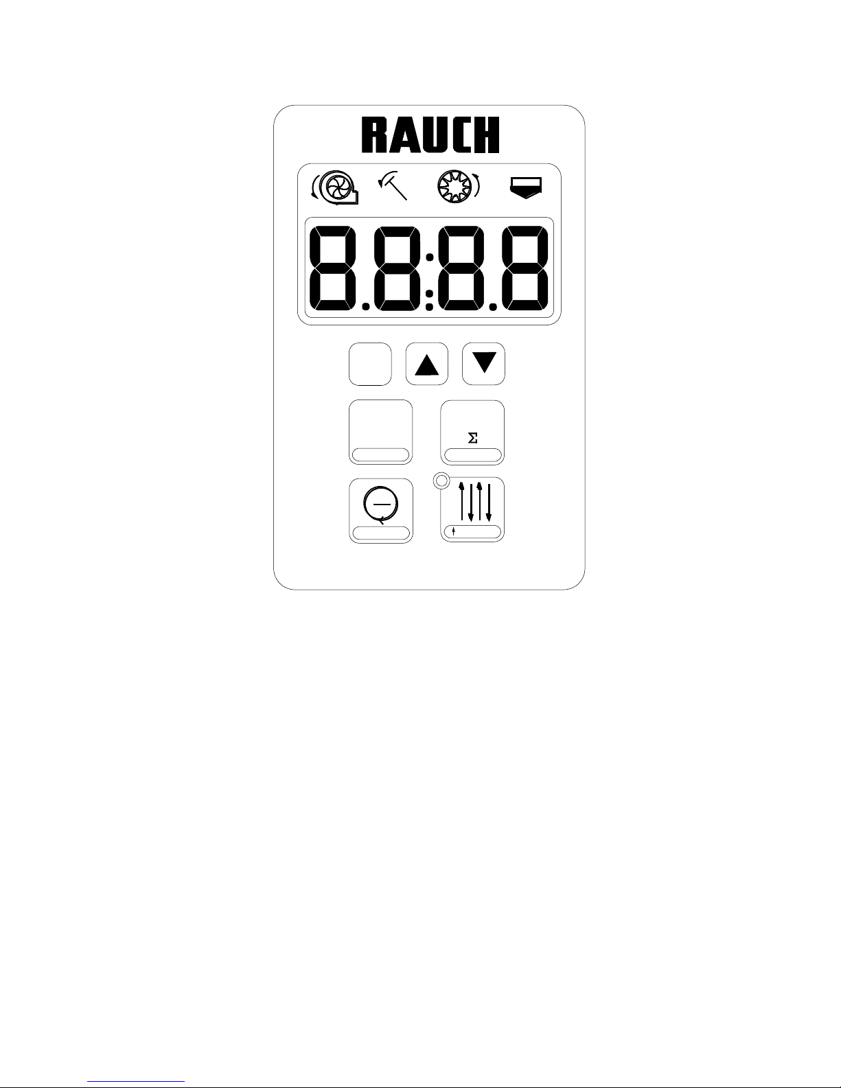
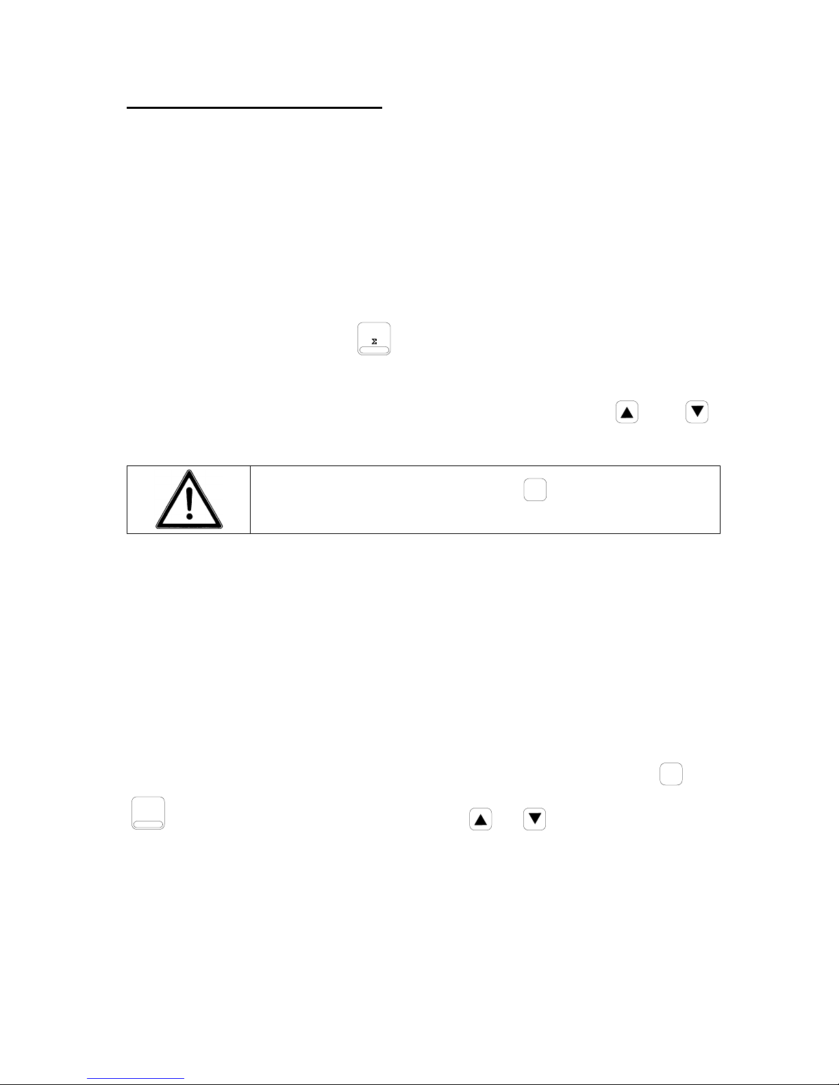
1 – Symbols
2 – Screen
3 – Arrows
4 – Functions key
5 – Area key
6 – Speed key
7 – Tramlining display
8 – Tramlining key
9 – Blower key
1 Symbols
Blower
Markers
Distribution
Seed level
3 Arrows
Option selection.
4 Functions key
Set system by activating this key when switching
on.
Second function of keys pressing this key
simultaneously.
Store the selected function by pressing and
holding.
5 Area key
Day and total recorder display.
Clear counters (Dual function).
Programme working width by pressing and
holding.
6 Speed key
Speed display.
Store speed (Dual function).
7 Marking display
LED lights while cutting rows.

4
8 Marking key
Display rhythm and current counter position.
Stop counting by pressing this key again.
Program rhythm by pressing and holding the
key.
Start marking at the start of the field (Dual
function).
9 Blower key
Blower rpm display.
Program nominal blower rpm by pressing and
holding this key.
Set alarm function (Dual function)

5
B Detailed description
B 1 Electrical power supply
The power supply to the HECTOR 3000 unit is via a
cable to the tractor 3 pin plug (DIN 9680, ISO
12369).
1
2
3
15/30
31
82
Pin
Wire colour
Function
15 / 30
Brown
+ 12 Volt
31
Blue
Earth
81
-
not used
B 2 VENTA
On the VENTA seed drills, the FS4 computer circuit
consists of the control unit (1), the junction box (2),
sensors and one or two control actuators.
The control unit connects to the junction box via the
7 pin plug (3). The connection diagrams are shown
on the following pages.
Sensor gaps (distance from metal or magnet)
1
3
Sensor
Gap
2
3
Blower
1 – 2 mm
Metering unit
0.4 – 0.8 mm
Markers
3 – 5 mm
Hopper sensor
- - -
6
C System configuration
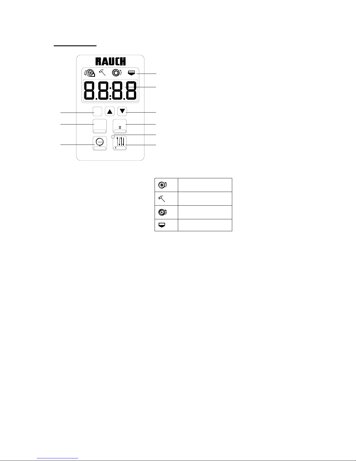
This is carried out by pressing the
F
key and switching on the 12 volt power to the
control unit simultaneously. The following settings may be changed or checked:
1) Type of seed drill (VENTA, BS, GC, Integra, etc.)
2) Number of tramlining control linear actuators
3) Checking screen
4) Checking sensors
Settings are stored by pressing the
F
key for 3 seconds until the
display flashes briefly!
The next parameter is configured by pressing the
F
key.
To exit the configuration menu, press one of the other keys.
C 1 Configuration of the type of seed drill
The and keys enable screen data to be changed:
to go to the next digit (the one selected flashes)
to alter the configuration value
Different machine configurations:
BS GC LOGISEME INTEGRA
mechanical seed drills
VENTA pneumatic seed drills
Precision seed drills PLANTER2,
MAXIMA
7
The digits displayed below the symbols mean the following:
t = Blower sensor (VENTA)
d = Distribution sensor (mechanical seed drills: BS, GC, Integra)
E = Single seed drills (Planter, Maxima)
Side markers
1 = Present
0 = Absent
Speed sensor
1 = Present
0 = Absent
Level sensor
1 = Present
0 = Absent
Settings are stored by pressing the
F
key for 3 seconds until the
display flashes briefly!
To input the next setting, press the
F
key briefly.
To exit the configuration menu, press one of the other keys.
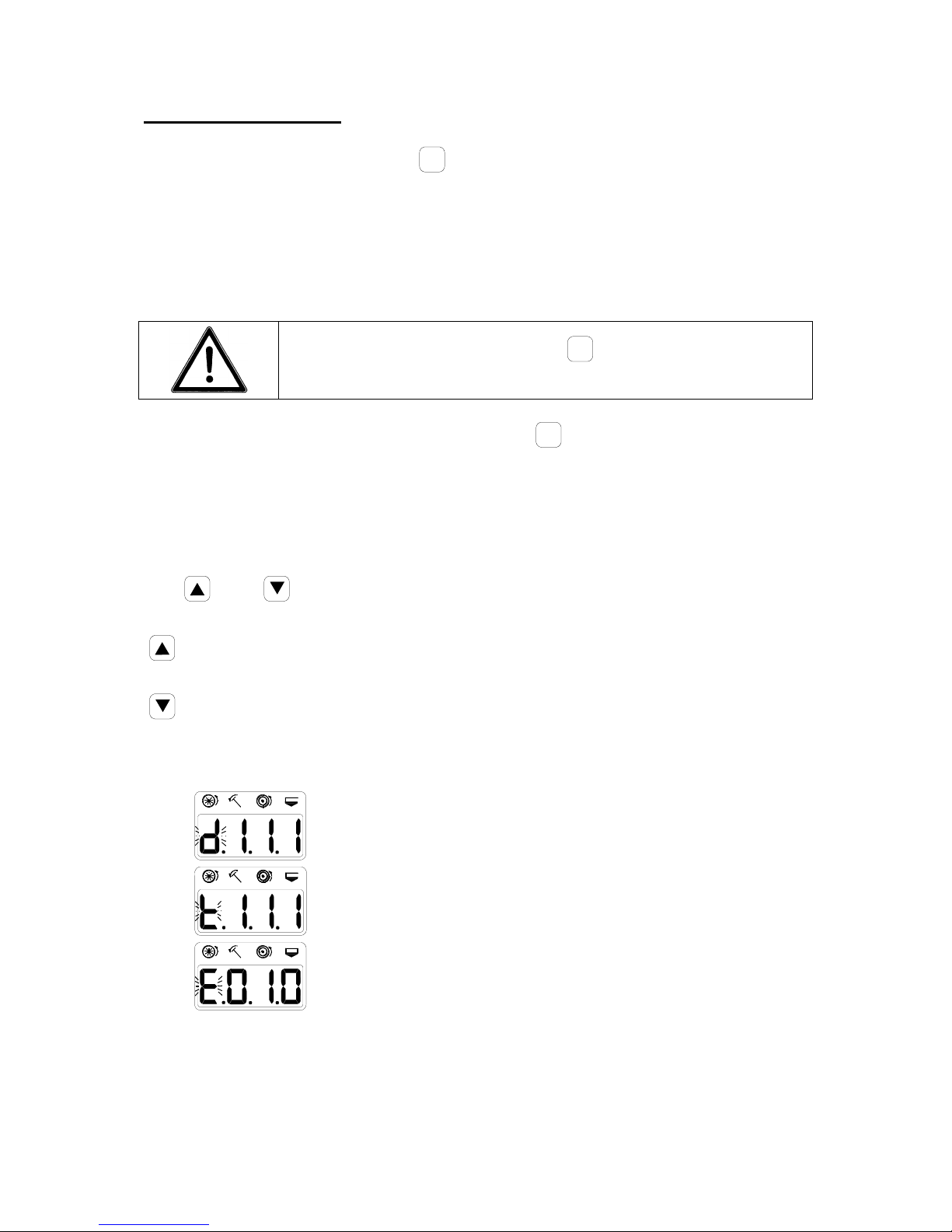
C 2 Configuring the number of actuators
The number of linear actuators required to control tramlining needs to be stored in
the memory (standard = 1; for special rhythms (option) = 2).
The screen can be tailored to the number of actuators fitted to the machine using the
and keys:
EL: 1 One actuator
EL: 2 Two actuators
Settings are stored by pressing the
F
key for 3 seconds until the
display flashes briefly!
To configure the next parameter, press the
F
key briefly.

8
To exit the configuration menu, press one of the other keys.
C 3 Checking the screen
By pressing the
F
key after configuring the actuators, the
screen can be checked for 2 seconds. The screen then changes
automatically to sensor tests.
C 4 Checking sensors
This menu appears automatically after the screen test. The various seeder functions
are to be checked and confirmed.
Machine function
Screen display
Switch on the blower
The top segment of the 1st digit
flashes.
Set the markers VENTA to
the raised position
The top segment of the 2nd digit
flashes.
Rotate the wheel
The top segment of the 3rd digit
flashes.
Cover the hopper sensor
The top segment of the 4th digit
flashes.
To configure the next parameter, press the
F
key briefly.
To exit the configuration menu, press one of the other keys.
9
D Setting the seed drill parameters
The following settings which are specific to the machine are to be carried out:
1) Working width
2) Wheel revolutions
3) Tramlining rhythm
4) Nominal blower rpm
5) Activate/cancel alarms
D 1 Width setting
In order to set the width, the
ha
2x ha
ha = 0
key should be pressed for approximately 3
seconds until the initial value stored flashes.
The desired width can be set by configuring the screen using the and
keys.
The setting is stored by pressing the
F
key for 3 seconds until
the display flashes briefly!
D 2 Storing travel pulses
In order to display the correct speed and for the hectares recorder to calculate
correctly, it is necessary to program the number of pulses for a 100 m run. Two
methods may be used: storing an average number of pulses in the memory or field
calibration. If it is performed correctly, field calibration provides increased accuracy,
since it allows for various soil types.
1) Programming the recommended number of pulses
The current stored value for a 100 m run can be displayed by pressing the
F
and
km/h
100 m
keys and may then be changed using the or arrows to set the value
to the required number as indicated in the table:
10
VENTA
Width
Value
/ 100 m
2.5 m
660
3.0 m
780
3.5 m
920
4.0 m
1050
4.5 m
1200
5.0 m
1300
6.0 m
1580
Settings are stored by pressing the
F
key for 3 seconds until the
display flashes briefly!
2) Field calibrating a 100 m run
The current stored value for a 100 m run can be displayed by pressing the
F
and
km/h
100 m
keys simultaneously. By then pressing the and keys simultaneously,
the count calibration mode (CAL) for the number of pulses for a 100 m run will be
activated.
To start the count at the marker for the start of the 100 m run, press the key
To stop the count at the marker for the end of the 100 m run, press the key
Settings are stored by pressing the
F
key for 3 seconds until the
display flashes briefly!
 Loading...