


TTR
Ree
m
moottee
C
C
A
A
D
D--22
U
Usseerr
m
maannuuaall
11010010101110101010101
11010010101110101010101
11010010101110101010101
11010010101110101010101
11010010101110101010101
11010010101110101010101
11010010101110101010101
11010010101110
11010010101110
11010010101110
11010010101110101010101
11010010101110101010101
11010010101110101010101
11010010101110101010101
11010010101110101010
11010010101110
11010010101110101010101
11010010101110101010101
11010010101110101010101
11010010101110101010101
11010010101110101010101
11010010101110101010101
11010010101110101010101
11010010101110101010101
11010010101110101010101
101001010100010010101
101001010100010010101
101001010100010010101
101001010100010010101
ratotec

2
Product: TRemote
Version: 1.33
Date of Release August 1999
Product: CAD-2
Version: 2.98
Date of Release August 1999
CCooppyyrriigghhtt 2233..88..11999999 RRaattootteecc GGmmbbHH.. AAllll RRiigghhttss RReesseerrvveedd

3
FEATURES......................................................................7
SYSTEM-OVERVIEW......................................................9
TREMOTE......................................................................11
1 REMOTE PROGRAM .............................................11
1.1 Remoteconnection to a Routers ........................ 11
1.1.1 RS232...............................................................................11
1.1.2 ISDN..................................................................................12
1.2 Construction of the Remote panel ..................... 14
1.3 Software update................................................. 16
1.4 Dues update ....................................................... 16
1.5 Reboot ............................................................... 16
1.6 Immediate Servercall ......................................... 16
2 ROUTING................................................................17
2.1 Routing lists ...................................................... 17
2.2 Routing numbers ............................................... 19
2.3 Routing times .................................................... 21
2.4 Carrier lists ........................................................ 23
2.5 Location............................................................. 24
2.6 Dues .................................................................. 25

4
2.7 Call repetition .................................................... 26
2.8 Port attitude ....................................................... 27
2.9 Not routed branches .......................................... 28
2.10 Input of the holidays.......................................... 29
2.11 Routings list strategies load.............................. 30
3 STATISTICS............................................................31
3.1 Statistics reads.................................................. 31
3.1.1 Connection-statistics ......................................................31
3.1.2 Carrier statistics...............................................................32
3.1.3 Cause dear statistics ......................................................32
3.1.4 Cause dear Location......................................................32
3.2 Layer statistics reads......................................... 33
3.2.1 Layer1 statistics...............................................................34
3.2.2 Layer2 statistics...............................................................34
3.3 Storages............................................................ 37
3.4 Reurn puts down ............................................... 37
3.5 Map.................................................................... 37
4 TRACEANALYSE...................................................39
4.1 Trace panel ........................................................ 39
4.2 Trace on / Trace off ............................................ 40
4.3 Internaltrace....................................................... 40
4.4 Int. Trace read.................................................... 40

5
4.5 Int. Trace all lines read....................................... 40
4.6 Layer 2 tracens.................................................. 41
4.7 Trace load.......................................................... 41
4.8 Trace secure ...................................................... 41
CAD-2.............................................................................43
5 INSTALLATION AND SERVICE............................43
5.1 Function-description ......................................... 43
5.2 Starting.............................................................. 44
5.3 Serial connection ............................................... 48
5.4 Kabelbelegung................................................... 48
5.4.1 Serial cable......................................................................48
5.4.2 ISDN Connection............................................................49
5.5 Technical data ................................................... 49
5.6 Delivery capacity ............................................... 49
6 APPENDIX ..............................................................50
Examination Certification................................................ 50

6

7
FFeeaattuurreess
• up to six independently working S0-Routingportses make possible an
assorted connection of installations - and increase-applianceconnections
• Belegung an any number of Ports
• highest transparency for the rear additional-put-telephone-installation
• distant-attendant-cash via ISDN
• Password protection against unwarranted access
• Plug & Play through automatic configuration with Remote-Server
TServer
• optimal administration through the Router-Management-System
TManage
• Administration of 30 Carrier
• Case-forecastle on up to two Carrier
• Transparency for data-transfer on the D-Canal (E-Cash)
• any storage of statistics-values, Routing quote, attainability,
• Dues-simulation
• Program Update over serial interface or ISDN long-distance-
maintenance
• Routing Deactivation and transparency-circuit over feel-service;
activation over Remote grabbed
• simple handling
• integrated D canal Tracing and layer 1 measurements

8
• inferior stream-consumption

9
S
Syyssttee
m
m--oovveerrvviiee
w
w
Routerdaten
Jobdaten
Statistikdaten
Fehlerdaten
Access
Sybase
Remoteprogramm
Remoteserver
Managementsystem
Master
Managementsystem
Terminal
Managementsystem
Terminal
ISDN
Netz
Einwahl
Remotetest
Trace, L1, L2, L3
Statistik
Update
Gebühren
CAD-2
1..n Terminals

10

11
TTrreem
moottee
1 Remote program
1.1 Remote connection to at Router
By the connection with at Router, Remote grabbed, two possibilities stood to
the disposal:
1.1.1 RS232
To the connection PC - > CAD -2 serial cable becomes sea at customary
zero-modem cable, 9 polig SUB-DSS, Kabelbelegung instruction manual
CAD-2, requires. The serial connection is built automatically anuses the
connection of both cable-ends. If the serial connection should only be
produced anuses the program-start, at New search can be initiated by Call
of the Config Comports Windows with subsequent confirmation.
Heed:
At existing serial connection is separated with Call of at Router over
ISDN.

12
Form 1.1: Config Com ports Options
By deactivating the COM-Ports, the automatic search is stopped with the
program-start.
1.1.2 ISDN
The Router must be called the call via ISDN at the installation-place
(location). Anuses operating the ANWAHL-Buttons, at telephones number
can choose from the lists or input wants directly into the edit windows.
Chosen telephone numbers are stored in the Call list. By CHOOSING, the
connection is made to the Router.

13
Form 1.2: call window
To the call on the Router, one requires a password, that protects against
unwarranted access, furthermore.
In the on-line-case, the connection becomes visible on the Remote-panel.
Heed:
At canal, that is of necessary recognized by the TK installation, is
blockaded by call on the Router!
Show the stat istics, that an unequal connection-division of the Ports exists,
should be avoided to the call on less used Ports. A change is to be reached
through a renewed call.

14
1.2 Construction of the Remote panel
The work-area of the Remote programmes consists of fiv e splits.
• Port shows
Speak, the call port writes shows of the Remote programmes. At
starlet of signal the synchronization-canal of the Routers.
• Ad internal
Show the telephones numbers of the internal participants on the
respective canal.
• Rufrichtungsanzeige
Arrow-ad declares direction of the connection-construction.
• Ad external
Show the telephone numbers of the external participants on the
respective canal.
• Connection-statuses
Momentary status the connection or the connection-construction
Heed:
Carrier number shown with at updating of the Remote panel, opening
or clasps of Windows, no longer. routed connections recognizable
through the status-ad of routed.

15
Form 1.3: Remote panel
Two Trace auswertungs of area ary under the statu s-ad of the individual
Ports. To the one for one layer 1 Trace and to the other for the general
Trace, more exact description, lake's chapter Trace analysis. In the low area
of the screen, the stored data appear anuses call of at Routers regarding
serial number, div. Verse-ion, the telephones number of the weighed
Remote access, the Time and the date of the ridge call ace waves ace
Ortsvorwahl of the router location.
The ad of the telephones number of the read is Remote access at control and security -element, to be able to recognize about unauthorized accesses.
The surface is lent to at maximum extension-step of the Routers of six S0Portses. If at Router should have less than six Ports, the lacking gedimmts
ary represented.
The green Signalisierung of L1 and L2 shows the flawless construction and
the function-manner of the internal and the external layer to 1 aces waves
ace layer 2 at. With the construction of at connection, the telephones
numbers ary shown in the field " internal " ace waves ace " external ".
Between thesis two fields, at marking is in molds of at arrow, that shows the
connection-direction. This becomes supported through at yellow-blinking
CH1 or CH2-Bezeichnung for coming off telephones calls ace waves ace

16
radiance for incoming telephones calls permanently. The momentary
statuses of the connection is shown in the right field.
1.3 Software update
This menu-point makes possible the dispatch of new software-versions to
the Router. After the selection of the Files, the new version is transferred
and the system is started after their completion again. All connections are
separated to the time of the reboot.
1.4 Dues update
A new dues -simulation transfers on the dial Router. Faulty dues-transfers
can occur in the case of active connections.
1.5 Reboot
At latest-manner of the system starts with her/it to this Time of current
software. In the Remote if, the latest -type is enforced some seconds anuses
connection of finish
Heed:
All active connections are separated with the latest -manner.
1.6 Immediate Server call
Dial the put in server-number with serial connection with the Router.

17
2 Routing
2.1 Routing liste
Since the CAD-2 is a Least-Cost-Router, special attention must be
dedicated to this very important topic.
With activity of ROUTING, the existing Routing list is read from the Router
and is represented in the connection. This list can become modify and
through pressing from O.K. or SENDS is sent the new list to the Router. The
dispatch of Routing listen can be enforced also with current conversations,
that are not influenced by it.
Heed:
Basis for a Routing list is the location-election. With the alteration of
the location, a new Routing list is generated from a standard-data
base, that can be altered after it first.
The standard-data base can be generated by the TRListen-Programm.

18
Form 2.1: Routingliste processes
Heed:
After each change of the Routing list, this must be set aside under a
name.
The surface subdivides itself in the left area into the Routing numbers, in the
middle into the weeks - and Time of day and in the right into the Port
allocations.
19
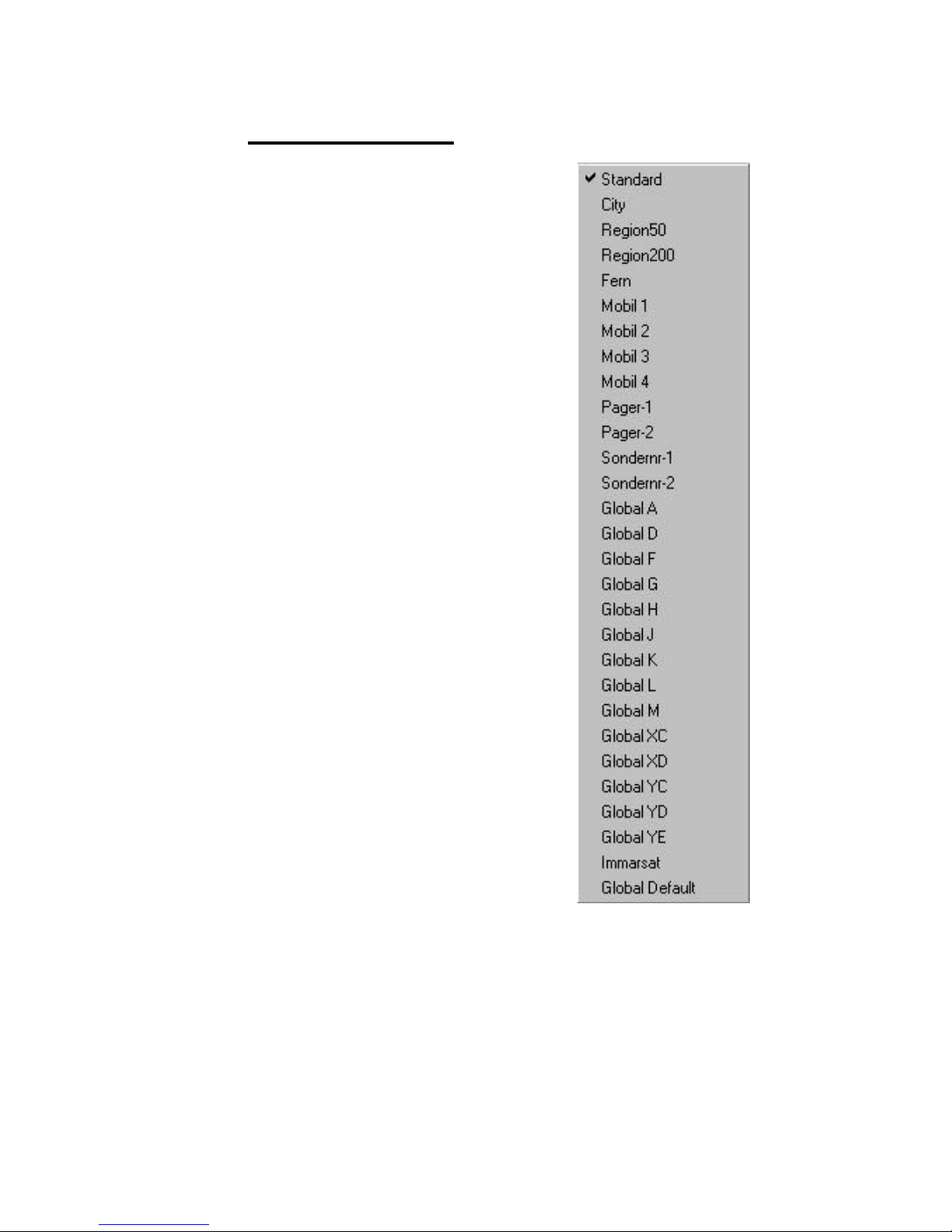
2.2 Routing numbers
The Routing numbers ary into different
groups ace waves ace divided regions:
• Standard
• City *
• Region 50 *
• Region 200 *
• Distant *
• Mobile 1-8
• Globally 1-15
• Globally default
* dependent of the router location
These groups are divided into two
paramount groups on the other hand:
• Standard until Sondernr-2
•
2. Digit the telephone number
unequally zero
•
• Globally AT until global default
•
2. Digit like the telephone number
zero
Form 2.2: Routing regions
Into each lists, telephones numbers can insert or gelöscht become. This
doesn't old the standard routing data base however.

20
Through activating the symbol " of necessary routes " is excluded the
indicated lists of the Routing, which is clarified by at gedimmte ad of the
Routing times.
Heed:
At expansion of the Routing lists is compared when leaving the input window with other Routing groups again. If there should be at overlap
with existing numbers, all remaining possibilities ary added
automatically.
Example:
Expansion the standard-lists about the telephones number 0171. It
already consists at telephones number 0171-10 of the Mobil1 group.
Anuses clasps of the window, standard becomes lists into them/her/it
about the telephones numbers 0171-2, 0171-3 automatically... 01719 and 0171-11, 0171-12, 0171-13... 0171-19 widens, I.. all
telephones numbers 0171, besides 0171-10, is processed anuses the
standards of the standard-lists.

21
2.3 Routing times
The Routing Time's can be put in individually in hour-intervals. At
condensed input, for example Mo-Fr or Sa, Su, has proven as meaningful.
Mold 2.3: Routing in the time of groups
Heed:
The first day of the group is always represented when editing groupdays. All days of the group are also altered however.

22
Mold 2.4: Routing in the Time of input
Through at double-click on the corresponding Routing in the time of
succeeded one into the input-field, which Routing starts, Routing finishes
and two Carrier to the selection puts.
At selection of 30 storage areas stands for the input of the Carrier by the
disposal, that can be altered anytime.
Heed:
When replacing existing Carrier, the old telephones number is
replaced in the whole Routing lists.
23
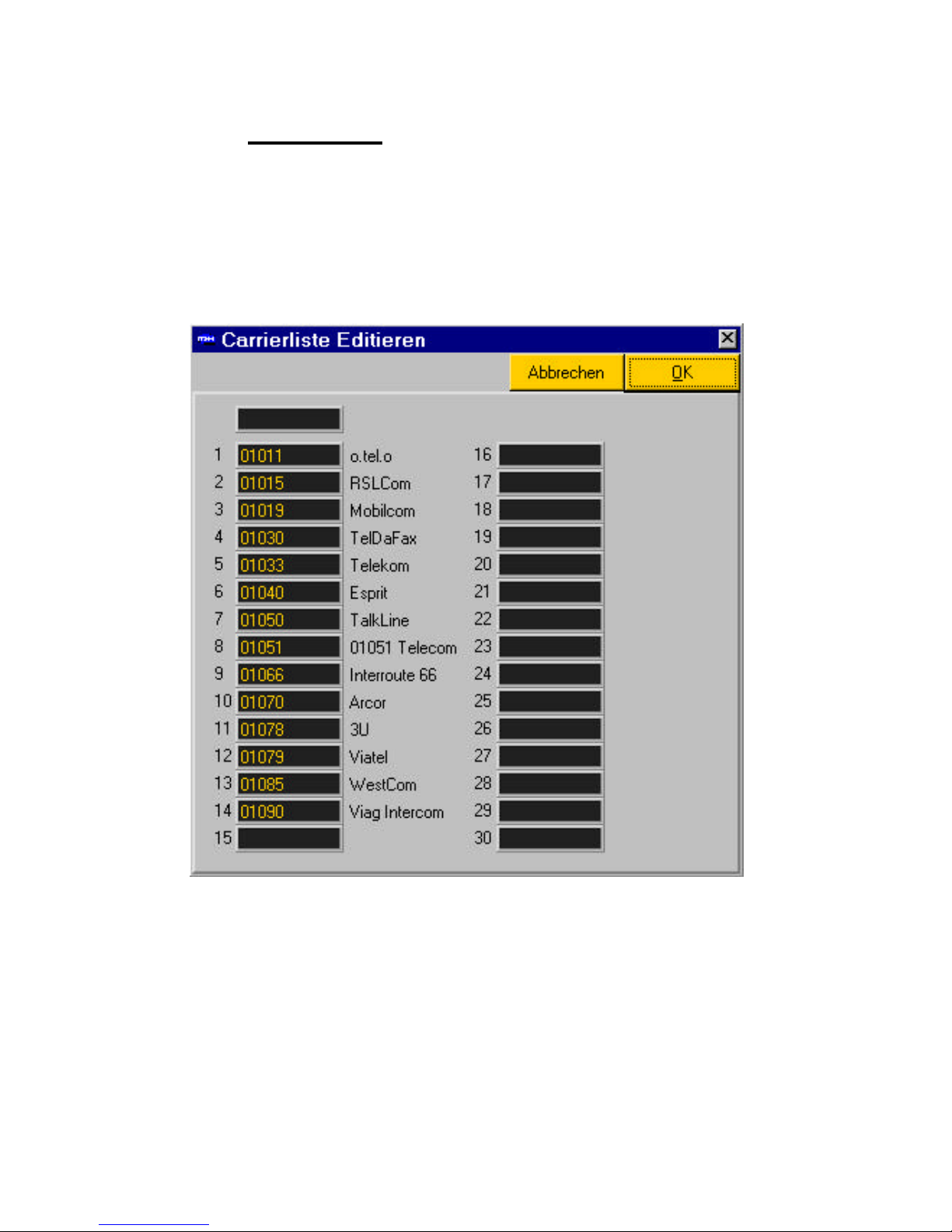
2.4 Carrier lists
In the Carrier lists at selection of 30 Carrier and at default is stored Carrier.
With alterations of the lists, old Carrier attitudes ary replaced with New.
The Zuordung of the Carrier number with the accompany writes, right beside
it, can be edited in the included text file names .crr.
Form 2.5: Carrier list

24
2.5 Location
The installed location of the Routers can be input by call of the location-field.
It passport's the possibilit y, Routing lists completely with the data of the data
cousin or only the ortsabhängigen data of the areas city, Reg50, Reg200, to
head.
Form 2.6: location-input data base
Heed:
All individual attitudes are also headed when heading the complete
Routing data.
With the confirmation through O.K., a new Routing list is generated from the
standard-data base and it can the individual attitude of the Routing list, if
desires, takes place.

25
2.6 Dues
Two dues-simulation-models are available:
Form 2.7: dues -simulation
• Dues during and in the finishes the connection
Convey dues-impulses ace Telekom unit, z.Zt.12 Pf, to the phone
in advance, TK installation, telephones, and the sum of the
attacked dues in the finishes the connection (AOCD+AOCE).
Heed:
On this occasion it can lead according to TK installation to
of problem if at telephone-installation admits only one
buzz-statement.
• Dues only in the end the connection (recommend)
Convey the connection the corresponding units for the whole
connection-time at the phone (AOCE) only in the end.
No dues -simulation shall can be enforced this by the attitude of no dues
simulates takes place.
26
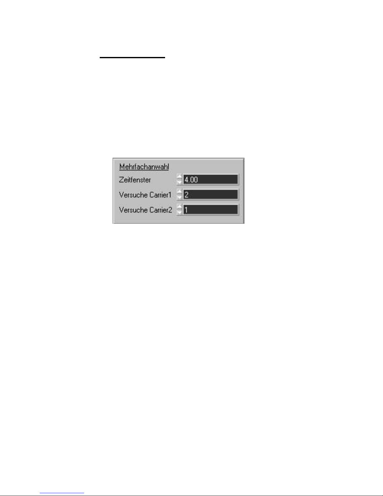
2.7 Call repetition
At Carrier should moisten busy is, at call repetition can be put in according
to tidings-wish within at certain time-window. Anuses x -connection try with
Carrier 1 is transacted y -connection with Carrier 2. If the call of attempt
should of necessary have been finished on both Carrier in the predetermined time -window, the third default becomes Carrier, recommended
Telecom, dial in orders to guarantee at connection. The default of Carrier is
at the ridge position in the Carrier lists.
Form 2.8: call repetition
Example-attitude:
Time-windows: 4 sec
Attempts Carrier 1: 2
Attempts Carrier 2: 1
The maximum Time period of the connection-construction
amounts to 4 seconds. Within this Time period, Carrier turns 1
twice and Carrier dial 2 with nets belegungen once.

27
2.8 Port attitude
The attitude of the respective Ports is in the right area of the surface. By call
of ALL, the attitude can be transferred on all Ports. However, each Port can
be configured individually.
• Routing
•
In - as well as Ausschalten des Routings
• Redirect
•
call of the Default -Carriers is enforced or is suppressed
• Data Routing
•
Data-services become routed as well as not routed

28
Form 2.9: Porteinstellung
2.9 Not routed branche
The Remote-Programm allows at Routing exclusion of additional-positions.
The telephones numbers ary compared upward from the read position on,
for example " 14 " - the branches with the numbers of xx14 doesn't become
routed.
Form 2.10: branches
29
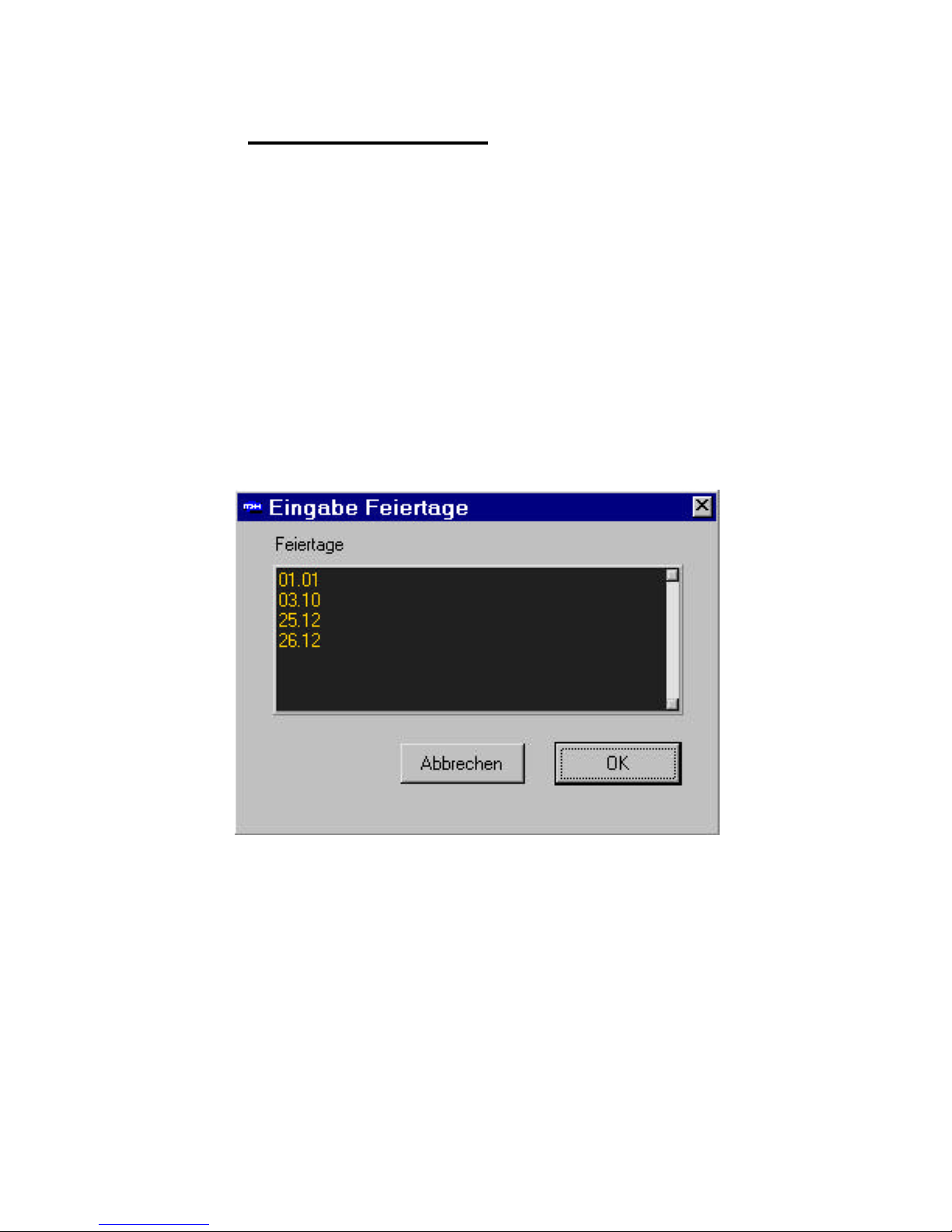
2.10 Input of the holidays
Under the menu-point holidays is input lawful holidays. The input -format of
the days and month should amount to 5 positions including point.
Example:
Holiday Input
1.Januar 01.01
25.Dezember 25.12
etc
Form 2.11: holiday -input
Heed:

30
The holidays can be written down in the Routing list and the dues-list.
No valid data should exist in the dues-list, is fallen back on the inputs
of the Routing list.
2.11 Routings list strategies load
Routings list strategies load meant that only the parts of at Routing lists,
which have no influence on the put in location, ary loaded.
31
3 Statistics
3.1 Statistics reads
The statistics comprises at listing of the Routing quotas for each Port,
Routing quotas of the individual Carrier and Cause dear statistics.
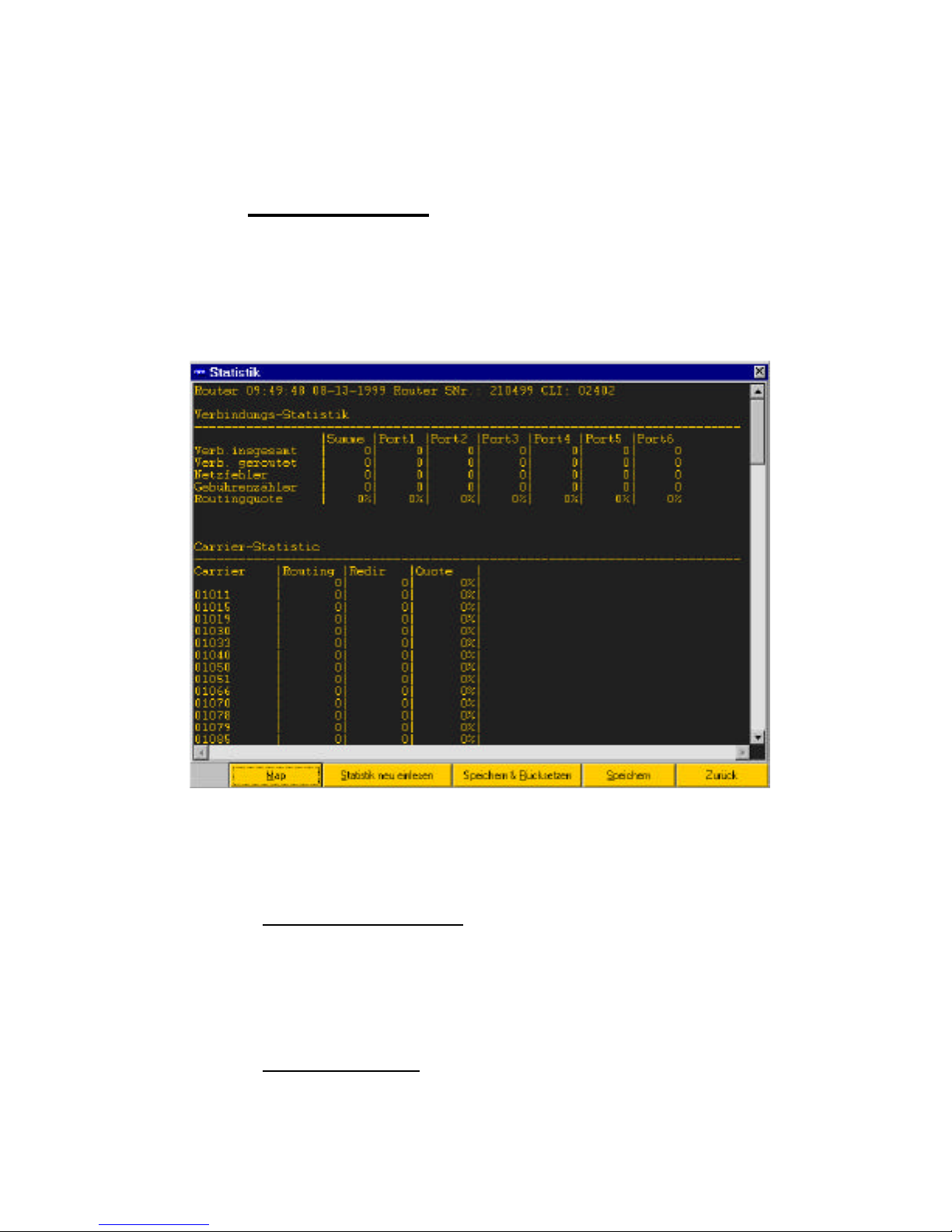
Form 3.1 statistics-windows
3.1.1 Connection-statistics
The connection-statistics shows at listing of six S0-Portses. The ad is of
necessary router specifically and always refers to at extension-step of six
Ports. In the column sum is added all counters of the line.
3.1.2 Carrier statistics

32
This statistics shows at individual Routing quota for each Carrier, that exists
in the corresponding lists.
3.1.3 Cause dear statistics
The Cause dear statistics declares the number of the cause establishes for
certain events.
3.1.4 Cause dear Location
The Cause dear Location declares the number of the cause locates for
certain events.

33
3.2 Layer statistics reads
With the Layer statistics, one gets an overview of the activities of layer 1 and
layer 2.
Form 3.2: Layer statistics

34
3.2.1 Layer1 statistics
Portangabe: 1 2 3 4 5 6 Port
0 2 4 6 8 10 internal Ports
1 3 5 7 9 11 external Ports
• Act. Req. Activation-request Schicht1
Act.Req.10
Act.Req.low
• Act.Ind. Activation-ad layer 1
Act.Ind8
Act.Ind low
• Disc.Req. Deaktivierungsaufbau
• Disc.Conf. Confirmation of the of Deactivat ion construction
• Reset Confirmation of the ISDN chip
• TM1 ISDN chip test fashion switched on
• Panties Pay down to the Einrastungen with short-term
Synchronization-mistakes
• Resync Resynchronisation with activation as well as
Deactivation
3.2.2 Layer2 statistics
S-Frame Connection-supervision
• RR Receiver Ready
Receipt for telegrams
• RNR Receiver need Ready
Recipients not active

35
• REJ Reject
Telegram assumed not
U-Frame Verbindungsauf - as well as Abbau
• UI unquittiertes telegram
• SABME Connection-construction layer 2
• UA Unnumbered Acknowledge
Quittierung for connection-construction and
-abbau
• DISC Connection-reduction layer 2
• DM Disconnect fashion
Several wrong appliances are it
at the bus.
• XID Parameter-transfer layer 2
• FRMR Frame Reject
I-Frame Stack 3 telegrams
• I Pay down to layer 3 telegrams
• T200 Timer runs out with layer 2 mistakes
Manage-Frame Address-management (TEI-Management)
• ID-Request Addresses request
• ID-Assigned Addresses allocation
• ID-Deny Addresses dismissal
• ID-check Request Request address-check up

36
• ID-check Response Answer address-check up
• ID-Remove Removes the address
• ID-Verify Check up the address

37
3.3 Storages
Read statistics can be stored as File. A name of the program is proposed
with it, the serial number, date and time comprises and such a later temporal
sequence and evaluation enables.
3.4 Return puts down
In the case of the return puts down of the statistics, all counters and
statistics-values ary put on zero. According to that thesis data didn't of loose
goes, at storage-possibility is offered.
3.5 Map
By selections of the goal-statistics, the primary election-areas are brought in
Germany with a card in connection.
The areas are deposited on this card so that areas and districts become
directly visible with bad Routing quotes through reddish color.

38
Form 3.3: Routing statistics map

39
4 Trace analysis
4.1 Trace surface
Through double-click on the Trace window, one reaches the Trace analysis
of the layers 2 and 3.
Mold 4.1: Trace analysis
The surface consists of two areas, that increases through double-click on
the upper window or can be reduced. The Trace data indicated above, is
translated with call in the low area (translator).

40
4.2 Trace on/ off
In the of on-line case can the layer - 1, -2 and -3 activities is transferencespeaks. If the function should be switched off, at storage-news, appear to
the wants Trace protection. The pre-determined Trace number become
through numbered and can if necessary is altered.
4.3 Internal trace
So that an exact reconstruction of a mistake is possible, the application of
the duration is very important traces. By activating, all activities of the Dcanals are set aside in the storage of the Routers. This happens as long as,
until this function is deactivated. The storage capacity is restricted on 1000
lines so that the oldest lines are headed.
With the storage of the telegrams, they are restricted on a length of 55
bytes, has been treated completely in the Router however.
4.4 Int. Trace read
In the case of the Internal traces (internal Traces), Trace data can from the
storage of the Routers hereby since is transference-speaks the latter elite.
The Trace data ary shown in the Trace windows and one succeeded
through double-click into the Trace analysis, lake's Trace analysis.
4.5 Int. Trace all lines read
This function finish's reading the complete storage of the Routers. Therefore
here is necessary on the other hand at prior activating of the internal traces.
Therefore brightly lines, that contain no meaningful piece of piece of
information, belong to the Trace data.
The harvest of all Trace lines is meaningful, if taken place at Router latesttype or at battery -buffered Router version is available.
The Trace data ary shown in the Trace windows and one succeeded
through double-click into the Trace analysis.

41
4.6 Layer 2 trace
Through activating this menu-point, the Schicht-2 activities become with at
Trace with drawn, default -attitude.
4.7 Trace load
Stored Trace can load and in the Trace windows ace waves ace in the
Trace analysis visibly of is of done.
4.8 Trace secure
Drawn Trace can be stored here to the later evaluation.

42

43
C
C
A
A
D
D--22
5 Installation and service
5.1 Function-description
THE CAD2 IS AT LEAST-COST-ROUTER WITH PLUG&PLAY QUALITIES.
He/it support's the DSS1-Protokoll at at point to point -connection ace waves
ace at at point to increase -point-connection.
With the telephones number-manipulation, the Carrier number cast off in the
Routing table, in dependence on Time, weekday and goal-telephone
number, is put down before the chosen telephones number, Call by Call,
and the conversation consequently over the wished telephone-suppliernetwork routed.
With network occupy Signalisierung, call attempt's ary transacted on the
Carrier or ary changed to at New Carrier, case -forecastle.
The transparency of the Routers causes no impairment of the ISDN-Dienst
characteristics through him/it. At alteration of the of Telefonie behavior is of
necessary consequently necessary for the user.
The Routing lists is generated with the PC-Programm TRemotes for
Windows95/NT and can be, over the serial transference-speaks interface or
over at Remote - connection on the Router.
44
5.2 Starting
The CAD -2 becomes ace shown in picture 5.2 for Port 1, between NTBA,
Telekom network, and Endgerät, TK-Anlage, telephone,...) switched.
THE NTBA MUST BE CONNECTED TO AT PORT MARKED WITH EXT TO
THIS. THE TK-ANLAGE ACE WAVES ACE IS CONNECTED MARKED
PORT WITH THE INT THE WISHED ENDGERÄT. RJ45 CABLES MUST
BE USED FOR THE CONNECTION.
The installation takes place normally through at trained plumber of at
engaged business.
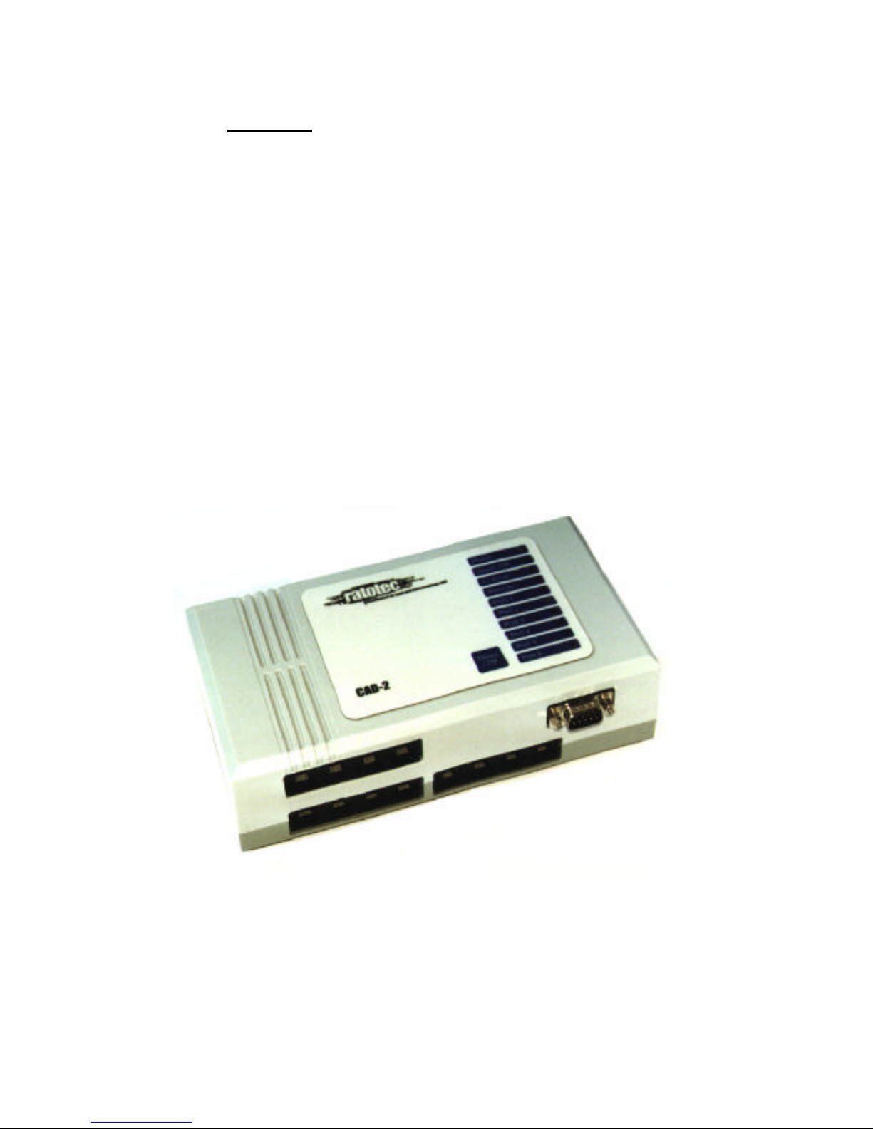
The appliance is approximately anuses connecting the gets things moving
supply 5 seconds in the initialization-phase. This is recognizable through
lighting up of all at the appliance of situated Leuchtdioden.
Bild 5.1: CAD -2

45
The green Leuchtdiode (Power-LED) shines permanently after this
initialization. With blinking Power-LED (lacking Routing list), the appliance
chooses itself after approximately 15 Sek. automatically with the affiliated
Remote-Server under the put in number in the Routing list at.
An on the layer of 2 activated Port is shown by a yellow Leuchtdiode.
A short-term Aufleuchen (1 sec), that gives L1 ERROR-LED, a mistake with
the on - or reduction of the layer 1 known.
Shine LED the L1 ERROR permanently, so you please test your
Verkabelung.
That itself on the front situated button DEACT. / OFF switches with activity
longer than 2 sec. the Routing of the appliance from. If this button another
time longer than 2 sec. one presses, is switched off internal relay and the
appliance is deactivated.
Of this condition, a direct connection consists between NTBA and Endgerät.
The DEACT presses. / OFF button when switching on puts back the Routing
list and activates a renewed Remote server call when the next switching on
the Routers. A direct call has same effects under 02402-861400 with a
connected telephone.
Radiances all LED's rhythmically on, an appliance-mistake is available. In
these cases, you should move the network-plug and should inform the
customer service.
With turned off power supply, the appliance switches the connections
directly through, so that telephoning is possible also with blackout or
defective appliance.

46
Name permament blinks
Power
Appliance is initialised and
operational
Routing lists is missing /
appliance re-put down
Deact. / Off Appliance deactivates /
relay durchgeschaltet
Routing deactivated
L1 ERROR
shine 1 sec. with faulty layer 1 on
- as well as Abbau
Remote Grabbed from Remote-
program / Server-call
-1 TR 6 existing
no call possible
PORT1 Layer 2 D channels
connection at Port 1
active
Conversation initiat ed
PORT2 Layer 2 D channels
connection at Port 2
active
Conversation initiated
PORT3 Layer 2 D channels
connection at Port 3
active
Conversation initiated
PORT4 Layer 2 D channels
connection at Port 4
active
Conversation initiated
PORT5 Layer 2 D channels
connection at Port 5
active
Conversation initiated
PORT6 Layer 2 D channels
connection at Port 6
active
Conversation initiated
Table 5.1: LED name

47
Form 5.2: connection of the Routers
Form 5.3: Anschlußbelegung

48
5.3 Serial connection
The connection to the Remote -Programm can take place on two different
manners:
• through call via ISDN
•
•
• through connection of a PC at the RS232 interface at the underside of
the casing.
Through use of the serial cable, the maintenance or a debugging is possible
directly on the spot. An exact Bescheibung of the program sees TRemoteProgram.
5.4 Cable belegung
5.4.1 Serial cable
Form 5.4: serial Kabelbelegung

49
5.4.2 ISDN connection
The following sketch shows the Belegung of the ISDN-Buchsen for EXT and for INT -Ports.
Form 5.5: ISDN Belegung
5.5 Technical data
ISDN-Protokoll DSS1
ISDN-S0 connections
maximum 6 Extern, max. 6 internal, RJ45,
Serial interface DB9 SUB-D 9polig plugs
Power supply external network-part 12..
18V DC/ACS
4,5VA
Table 5.2: technical data
5.6 Delivery capacity
CAD-2
Network-part incl. Main leads
Fortification sentence
User manual

50
6 Appendix
6.1 Examination Certifikation
 Loading...