

Page 1
USB-SPI/I2C Protocol Emulator
2013.10
Rev. 1.0
Page 2

REX-USB61 USB-SPI/I2C Protocol Emulator
1. Introduction --------------------------------------------(1-1) Specifications of the product
(1-2) Package contents
(1-3) Cable specifications
(1-4) Each mode
(1-5) Connection of a SPI device
(1-6)Connection of a I2C device
2. Setting up on Windows
(2-1) Setup on Windows 8 x32/8 x64/7 x32/7 x64/Vista x64
(2-2) Setting up on Windows Vista x32
(2-3) Setting up on Windows XP x32/XP x64
(2-4) Confirmation of setting REX-USB61
(2-5)
Uninstallation on Windows 8 x32/8 x64/7 x32/7 x64/Vista x64
(2-6) Uninstallation on Windows Vista x32/XP x32/XP x64
3. SPI/I2C Control Utility
(3-1) Functions of the Utility
(3-2) Explanation of the Utility
(3-3) Example to control by using this utility
(3-4) Grammar for script description
(3-5) Example of script
4. API Function reference
(4-1) Using on VC
(4-2) Using on VB / Visual C#
(4-3) List of API functions
(4-4) Detail of API functions
(4-5) Error Codes
(4-6) Sample applications
(4-7) How to develop application using this API functions
---------------------------------------
---------------------------------------
---------------------------------------
1- 1
1- 1
1- 3
1- 4
1- 5
1- 6
1- 9
2- 1
2- 1
2- 3
2- 5
2- 6
2- 7
2- 8
3- 1
3- 1
3- 2
3- 8
3-13
3-18
4- 1
4- 1
4- 3
4- 8
4- 9
4-24
4-25
4-27
Page 3

1.Introduction Page.1-1
(1-1) Specifications of the product
REX-USB61 enables you to easily control from a PC a variety of devices with
SPI/I2C bus.
[This product comes with SPI/I2C control utility]
This bundled utility can control SPI/I2C, GPO(General Purpose Output) and
save a setting file or log file.
For further information, please refer to Chapter 3.
[This product also comes with API library and sample program]
Making an application software with the API library enables you to control
the following:
・ Can provide a power supply of 3.3V or 5.0V([N.B.] current is under
100mA) from this product to an external device.
・ Can provide from 1.8V to 5.0V an input/output level of SPI/I2C/slave
port/parallel out port as long as a power supply terminal of this product
is provided by a external voltage.
・ Can change SPI/I2C, master/slave(SPI is a master only)
・ Can specify a frequency of SPI/I2C bus.
・ Can output a digital of 4bit at I2C mode.
And this product comes with program source codes by which you can use API
library.
(For further information on functions, please refer to (4-4) at Chapter 4.
Further information on applications, please refer to (4-6) at Chapter 4.)
[The latest firmware is available through our website]
You can update firmware in order to add or change specifications on this
products. The latest firmware and update program is available through our
website.
Page 4

1.Introduction Page.1-2
Hardware specifications
Item Specifications
Host Interface USB2.0 Full Speed Device
Connector USB mini B connector
Voltage 5V (via USB bus power)
Consumption Current 100mA
Device Interface
Input/Output level
Dimension 57(W) x 75(D) x 18(H) mm
Weight Approx.60g (except cable)
Operating
Environment
SPI Master Max. frequency 12MHz
I2C Master/Slave Frequency 47KHz~1MHz
[Output] 3.3V/5V
[Input] 1.8V - 5.0V is enabled with external P/S
Temperature:5~55℃ Humidity:20~80%
(non condensing)
Support Operating System
Windows 8/7/Vista/XP * Works both 32bit OS and 64bit OS
Software
Item File Description
Setting file
for installation
Installer USB61_Setup.exe
USB61.inf
Setting file for REX-USB61
(Windows Vista x32/XP x32/XP x64)
Installer for Windows 8 x32/8 x64/
7 x32/7 x64/Vista x64
Utility Usb61Uty.exe Utility to control SPI/I2C
Script file
Sample program
(VC6.0/VB6.0/VB
2005/C#)
Library
ActiveX control usb61api.ocx ActiveX control for REX-USB61
Uninstall utility USB61_uninst.exe
I2C_script.txt
SPI_script.txt
EEPROMRWUty
I2cSlaveSample
usb61api.dll
usb61def.h
usb61api.bas
usb61api.vb
Script file for I2C bus control
Script file for SPI bus control
Sample program to send/receive
SPI/I2C
Sample program for I2C slave
Library to control SPI/I2C devices
Header file for Visual C
Module for Visual Basic
Code file for Visual Basic
Utility to delete INF file
(Windows XP x32/XP x64)
* REX-USB61 can only use 1 device.
On the other hand, REX-USB61M can use multiple devices.
Page 5

1.Introduction Page.1-3
A
(1-2) Package contents
REX-USB61 package includes:
☑ REX-USB61
☑ CD-ROM
☑ USB A – mini B cable
☑ SPI/I2C cable
☑ Warranty Card
SPI/I2C cable
(For specifications, please see a next page)
USB mini B(Female) connector
Power LED (Power On : Green Power Off : Off)
ccess LED (Access : Orange Non-Access : Off)
Page 6

1.Introduction Page.1-4
(1-3) Cable Specifications
The below explains the specifications of the cable bundled with REX-USB61.
Pin
number
Housing
color
Cable
Signal Usage
color
1 Black Brown Power
2 Black Red Power
3 Black Orange 1MHz - SCL
4 Black Yellow 1MHz - SDA
Input/Output of power supply for a
target device
(Output 5V or 3.3V @100mA)
(Input 1.8V - 5V )
Input/Output of power supply for a
target device
(Output 5V or 3.3V @100mA)
(Input 1.8V - 5V )
Clock for I2C
(401KHz - 1MHz bus voltage 5V only)
(Pull-up resistance 10kΩ)
Data signal for I2C
(401KHz - 1MHz bus voltage 5V only)
(Pull-up resistance 10kΩ)
5 Black Green SCL
Clock for I2C (47KHz-400KHz 1.8-5V)
(Pull-up resistance 10kΩ)
Data signal for I2C
6 Black Blue SDA
(47KHz-400KHz 1.8-5V)
(Pull-up resistance 10kΩ)
Clock signal for SPI
7 Black Purple SCK
(12MHz 1.8 - 5V)
8 Black Gray SDO Data out signal SPI (12MHz 1.8 - 5V)
9 Black White SDI Data in signal SPI (12MHz 1.8 - 5V)
10 Black Black Reserve N/A(Don’t use)
* Don’t use I2C 401KHz-1MHz(Pin#3,4) and SPI(Pin#7,8,9) at the same time.
Page 7

1.Introduction Page.1-5
Pin
Housing color
number
11 White(Gray) Gray GND Ground
12 White(Gray) Red GND Ground
13 White(Gray) Orange DO0 SS0 for SPI/PORT0 for I2C (1.8 - 5V)
14 White(Gray) Yellow DO1 SS1 for SPI/PORT1 for I2C (1.8 - 5V)
15 White(Gray) Green DO2 SS2 for SPI/PORT2 for I2C (1.8 - 5V)
16 White(Gray) Blue DO3 SS3 for SPI/PORT3 for I2C (1.8 - 5V)
17 White(Gray) Purple GND Ground
18 White(Gray) Gray GND Ground
19 White(Gray) White N.C. N.C.
20 White(Gray) Black N.C. N.C.
Cable
Signal Usage
color
(1-4) Each mode
The below explains master/slave mode on SPI /I2C bus.
Bus Operation
This mode can select a slave, send data,
SPI Bus Master mode
display data received from the slave.
This mode can send data to a particular
Master mode
address, display data received from the slave.
I2C Bus
This mode can display data received to self
Slave mode
-address, send data to master.
You can select master mode or slave mode of REX-USB61 by the bundled
utility software or API library.
Page 8
1.Introduction Page.1-6
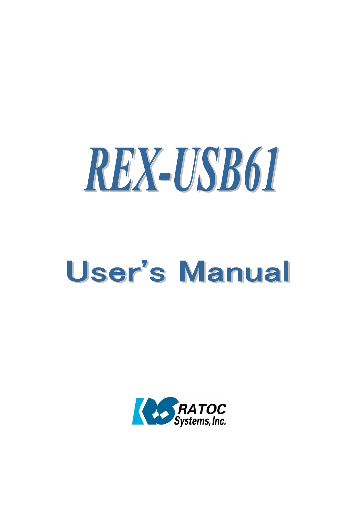
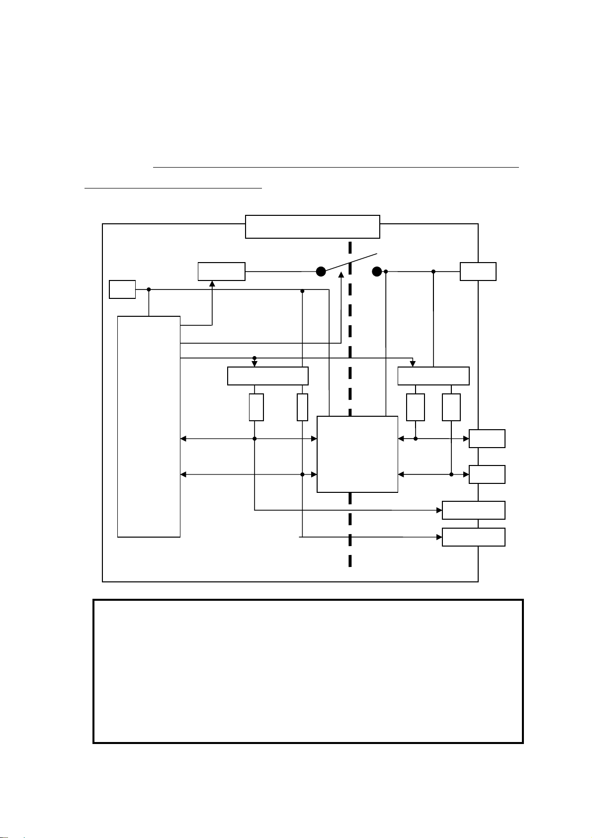
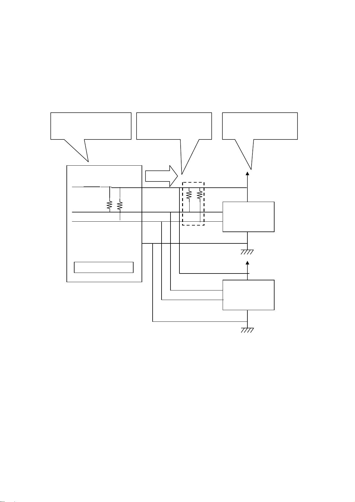
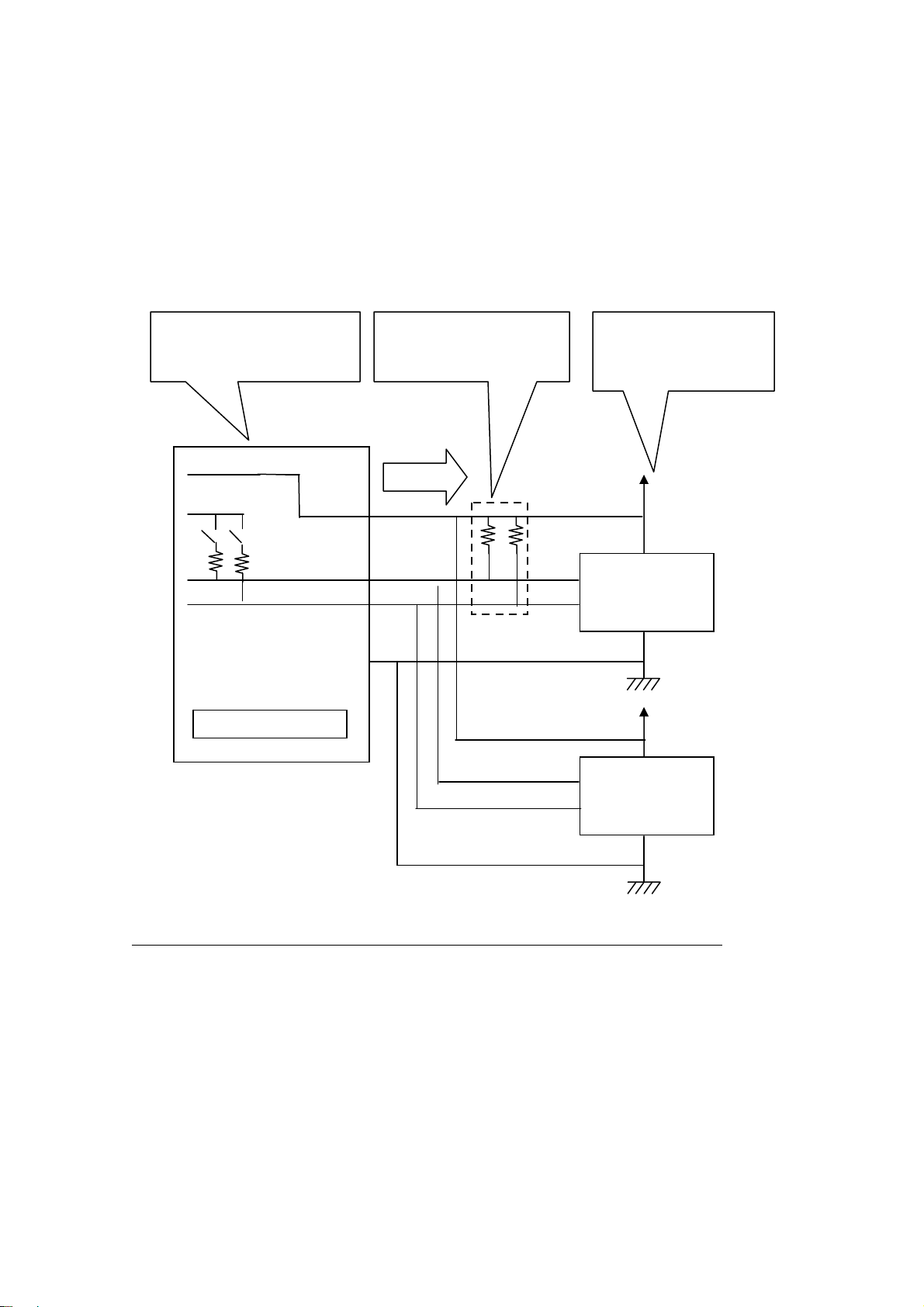
(1-5) Connection of a SPI device
The below explains how to connect an EEPROM with SPI interface.
・ Regarding power supply of REX-USB61
In order to provide power supply to a level converter IC on the
REX-USB61, it is required to connect the power pin of the REX-USB61 to
a power supply of a target device, even if the target device doesn’t have
power supply.
5V
USB PIC
Inside of REX-USB61
5Vor3.3V
Level converter IC
Power
10KΩ
10KΩ
10KΩ
SDO
SDI
SCK
DOx
[ Caution ]
When connecting/disconnecting a device, never provide power
to REX-USB61 nor the device.
(If you provide power to REX-USB61 or the device and connect
or disconnect the device, REX-USB61 will be broken.)
Page 9
1.Introduction Page.1-7
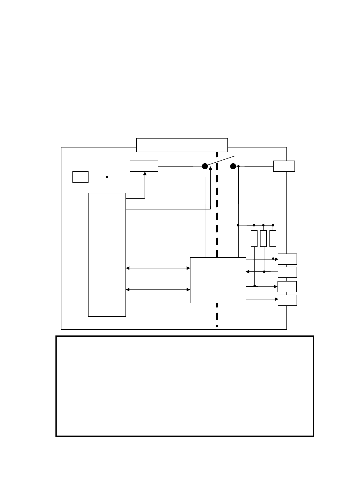
SPI Connection( If a target device has power supply)
If a target device has power supply, please disable power supply by utility
software or application which uses an API library.
( The library is called usb61_power_control(). Refer to (4-4) at Chapter 4.)
Disable output of power
supply of REX-USB61.
Power
● ● ●
●
●
SDO
●
●
SDI
●
SCK
DO0
DO1
DO2
DO3
GND
REX-USB61
Be sure to connect the
power terminal.
●
●
●
●
A target device
supply power.
Power
● ●
SI
SO
SCK
#CS
SI
SO
SCK
ATMEL:
AT25080A
●
Power
●
ATMEL:
AT25080A
#CS
●
Page 10
1.Introduction Page.1-8
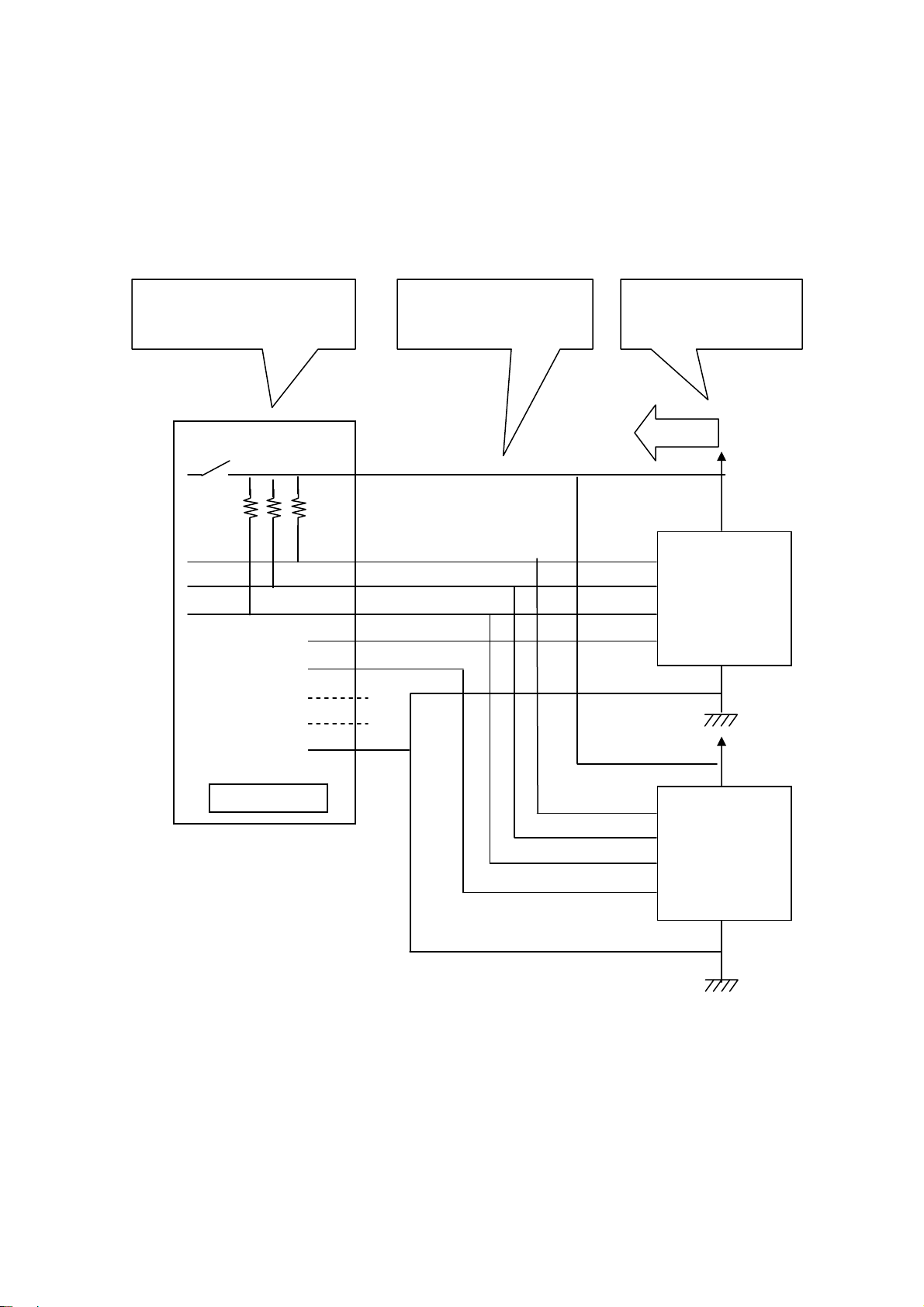
SPI Connection( If a target device doesn’t have power supply)
If REX-USB61 supply power(3.3V/5.0V) to a target device, please use utility
software or application which uses an API library.
( The library is called usb61_power_control(). Refer to (4-4) at Chapter 4.)
REX-USB61 output
power supply.
Be sure to connect the
power terminal.
A target device doesn’t
supply power.
●
●
●
●
REX-USB61
●
●
Power
●
SDO
●
SDI
SCK
DO0
DO1
DO2
DO3
GND
Power
● ●
SI
●
●
SO
SCK
●
ATMEL:
AT25080A
#CS
●
●
Power
●
SI
SO
SCK
ATMEL:
AT25080A
#CS
●
Page 11
1.Introduction Page.1-9
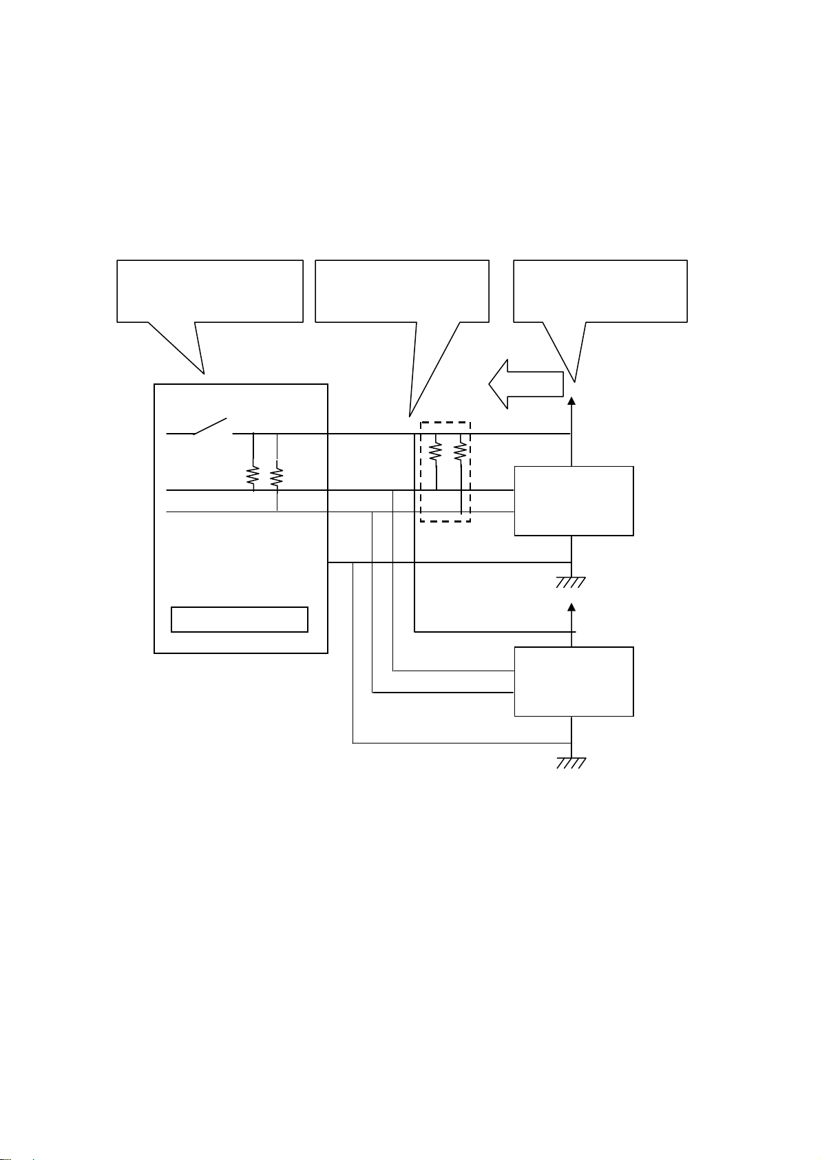
(1-6) Connection of a I2C device
The below explains how to connect an EEPROM with I2C interface.
・ Regarding power supply of REX-USB61
In order to provide power supply to a level converter IC on the
REX-USB61, it is required to connect the power pin of the REX-USB61 to a
power supply of a target device, even if the target device doesn’t have power
supply.
5V
USB PIC
5Vor3.3V
Inside of REX-USB61
Pull up control
10KΩ
10KΩ
Level converter IC
Pull up control
10KΩ
10KΩ
1MHz-SDA
Power
SDA
SCL
1MHz-SCL
[ Caution ]
When connecting/disconnecting a device, never provide power
to REX-USB61 nor the device.
(If you provide power to REX-USB61 or the device and connect
or disconnect the device, REX-USB61 will be broken.)
Page 12
1.Introduction Page.1-10
A
A
I2C connection( If a target device has power supply)
If a target device has power supply, please disable power supply by utility
software or application which uses an API library.
( The library is called usb61_power_control(). Refer to (4-4) at Chapter 4.)
Disable output of power
supply of REX-USB61.
Be sure to connect the
power terminal.
A target device supply
power.
●
●
●
●
Power
●
●
●
SDA
SCL
●
●
●
●
●
●●
●
※1
SDA
SCL
ATMEL:
AT24C02B
●
Power
ddress
50h
● ●
GND
●
REX-USB61
SDA
SCL
*1 The pull-up resistance on REX-USB61 is 10KΩ.
If necessary, add pull-up resistance.
●
Power
●
ATMEL:
AT24C02B
●
ddress
51h
Page 13
1.Introduction Page.1-11
A
A
I2C connection( If a target device doesn’t power supply)
If REX-USB61 supply power(3.3V/5.0V) to a target device, please use utility
software or application which uses an API library.
( The library is called usb61_power_control(). Refer to (4-4) at Chapter 4.)
REX-USB61 output
Be sure to connect the
power terminal. power supply
A target device doesn’t
supply power.
●
●
●
●
Power
●
●
●
SDA
SCL
●
●
●
●
●●
SDA
●
SCL
●
ATMEL:
AT24C02B
※1
●
Power
ddress
50h
● ●
GND
●
REX-USB61
*1 The pull-up resistance on REX-USB61 is 10KΩ.
If necessary, add pull-up resistance.
SDA
SCL
●
Power
●
ATMEL:
AT24C02B
●
ddress
51h
Page 14
1.Introduction Page.1-12
A
A
I2C connection [1MHz-SCL / 1MHz-SDA] ( If a target device has power supply)
If a target device has power supply, please disable power supply by utility
software or application which uses an API library.
( The library is called usb61_power_control(). Refer to (4-4) at Chapter 4.)
Disable output of power
supply of REX-USB61.
5V
5V
● ●
●
●
●
●
●
●
●
●
1MHz-SDA
1MHz-SCL
REX-USB61
Power
GND
Be sure to connect the
power terminal.
●
●
●
●
SDA
SCL
SDA
SCL
A target device
supply power.
Power
●
ATMEL:
AT24C02B
●
Power
●
ATMEL:
AT24C02B
ddress
50h
ddress
51h
●
* Only after providing power to all devices, set on pull-up resistance.
* If a target device provide power, don’t attach pull-up resistance on I2C bus.
Page 15
1.Introduction Page.1-13
A
A
I2C connection [1MHz-SCL / 1MHz-SDA] ( If a target device doesn’t have power supply)
If REX-USB61 supply power(5.0V) to a target device, please use utility
software or application which uses an API library.
( The library is called usb61_power_control(). Refer to (4-4) at Chapter 4.)
REX-USB61 output
power supply
Be sure to connect the
power terminal.
A target device
supply power.
5V
5V
●
●
●
●
● ●
●
●
●
●
Power
1MHz-SDA
1MHz-SCL
●
●
●
●
●●
●
※1
SDA
SCL
ATMEL:
AT24C02B
●
Power
ddress
50h
GND
●
●
REX-USB61
SDA
SCL
ATMEL:
AT24C02B
Power
●
ddress
51h
●
* Only after providing power to all devices, set on pull-up resistance.
*1 The pull-up resistance on REX-USB61 is 10KΩ.
If necessary, add pull-up resistance.
Page 16
2.Setting up on Windows Page.2-1
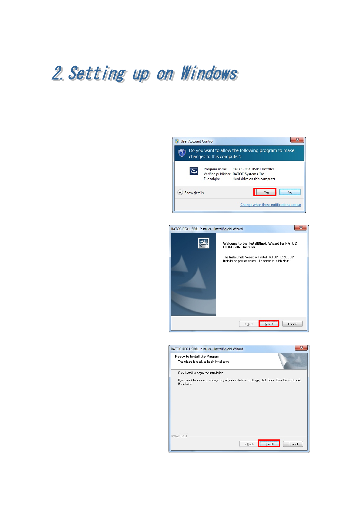
(2-1) Set up on Windows 8 x32/8 x64/7 x32/7 x64/Vista x64
Turn on the PC and proceed to the below installation before connecting
REX-USB61 to the USB port.
Start
Win8_7_VistaX64¥USB61_
Setup.exe at the bundled
CD-ROM.
If user account window appear,
click [Yes].
RATOC REX-USB61 Installer
will start. Click [Next].
Click [Install].
Page 17

2.Setting up on Windows Page.2-2
Click [Install] on the Windows
Security window.
The set up has finished.
If REX-USB61 is connected to
the PC, the installation will
automatically finish.
Proceed to (2-4) Confirmation of setting REX- USB61 to confirm the
installation has finished properly.
Page 18
2.Setting up on Windows Page.2-3
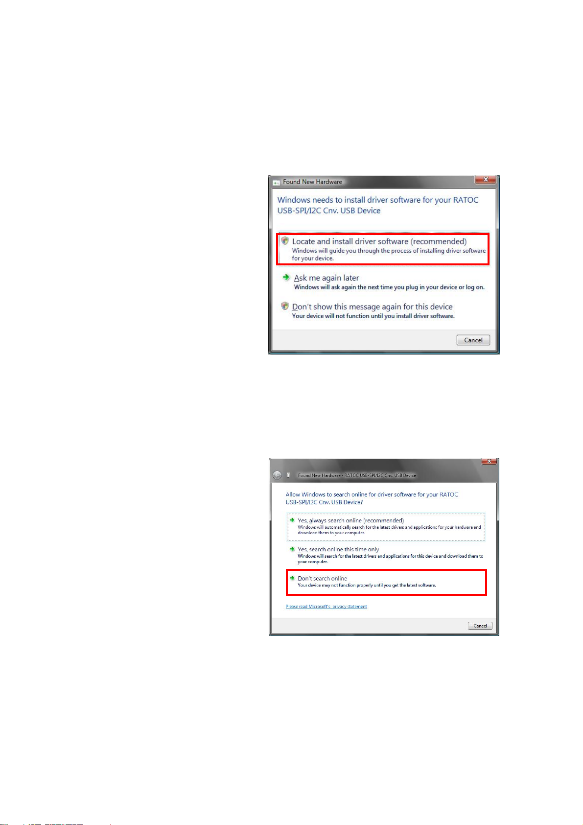
(2-2) Setting up on Windows Vista x32
Turn on the PC and connect REX-USB61 to the USB port.
The below hardware wizard will start up. Proceed to the below instruction.
Select [Locate and install driver
software (recommended)].
If user account window appear,
click [Yes].
Click [Don’t search online],
as shown right.
Page 19
2.Setting up on Windows Page.2-4
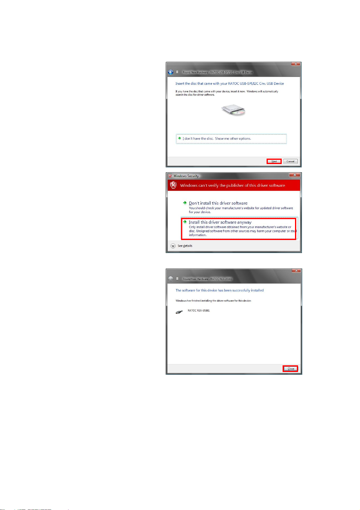
Insert the bundled CD-ROM
and click [Next].
Select [Install this driver
software anyway].
The installation of REX-USB61
has finished.
Proceed to (2-4) Confirmation of setting REX- USB61 to confirm the
installation has finished properly.
Page 20
2.Setting up on Windows Page.2-5
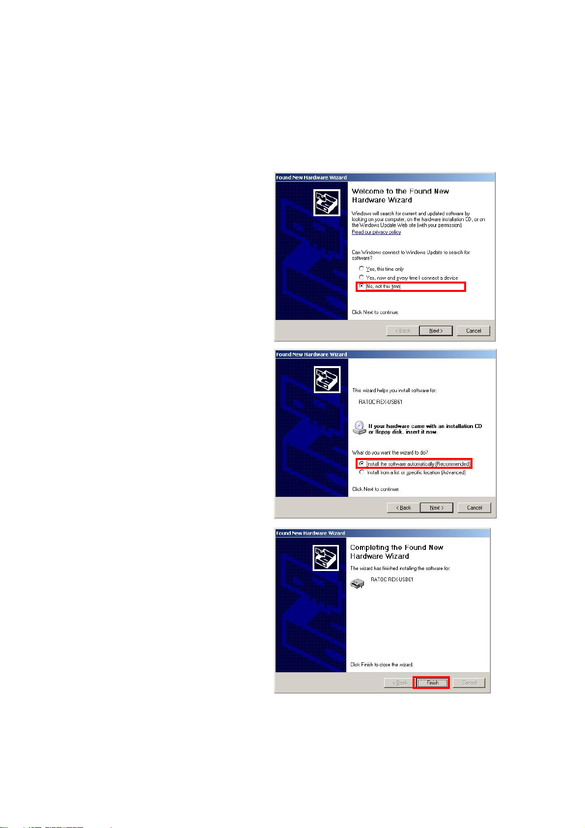
(2-3) Setting up on Windows XP x32/XP x64
Turn on the PC and connect REX-USB61 to the USB port.
The below hardware wizard will start up. Proceed to the below instruction.
Select [No, not this time] and
click [Next].
Insert the bundled CD-ROM
and select [Install the software
automatically(Recommended)]
and click [Next].
The installation of REX-USB61
has finished.
Proceed to (2-4) Confirmation of setting REX- USB61 to confirm the
installation has finished properly.
Page 21
2.Setting up on Windows Page.2-6
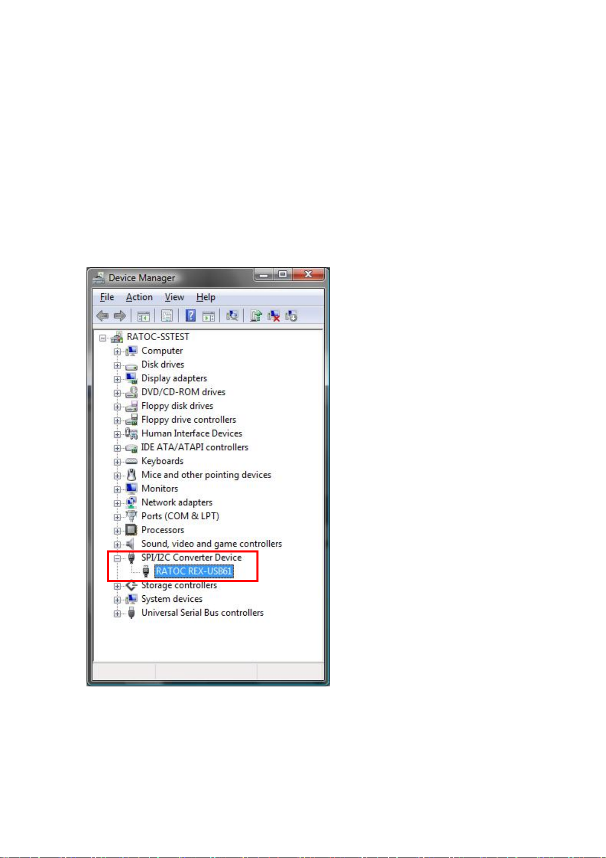
(2-4) Confirmation of setting REX- USB61
Open [Device Manager].
(※ On Windows XP x32/XP x64, open [Control Panel] and [System].
And select the [Hardware] tab and click the [Device manager] button.)
Confirm there is a string of [RATOC REX-USB61] properly under the
[SPI/I2C Converter Device].
Page 22

2.Setting up on Windows Page.2-7
(2-5)
Start [Programs and Functions].
Select [RATOC REX-USB61
Installer] and click [Uninstall].
Click [Yes].
Uninstallation on Windows 8 x32/8 x64/7 x32/7 x64/Vista x64
The uninstallation of
REX-USB61 has finished.
Page 23
2.Setting up on Windows Page.2-8
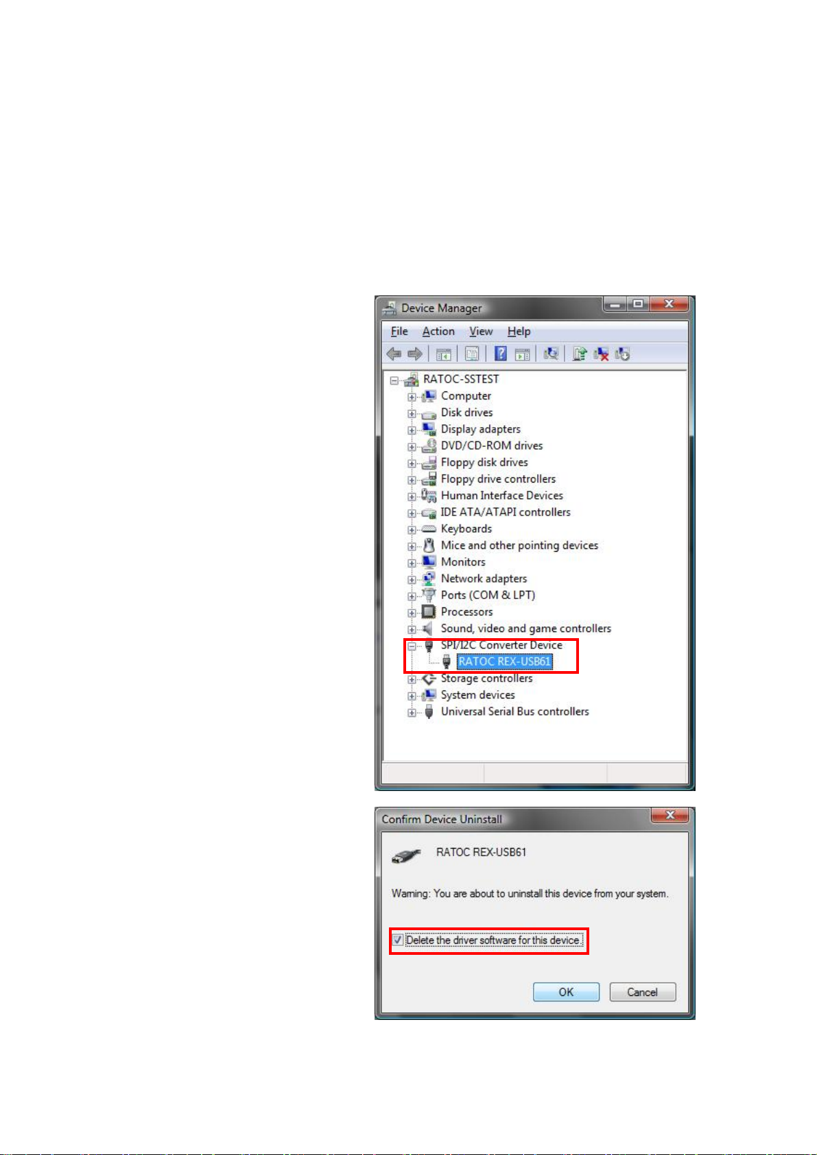
(2-6) Uninstallation on Windows Vista x32/XP x32/XP x64
To uninstall REX-USB61, you have to delete the driver and INF file.
(On Windows Vista, you have to delete the driver only.)
・Delete the driver
Open [Device Manager].
(※ On Windows XPx32/XPx64,
open [Control Panel] and
[System].
And select the [Hardware] tab
and click the [Device manager]
button.)
Right-click the [RATOC
REX-USB61] and select
[Uninstall].
On Windows Vista x32, put the
check mark, as shown right
and click [OK].
Page 24

2.Setting up on Windows Page.2-9
・Delete INF file
(Windows XPx32/XPx64)
Start [USB61_uninst.exe] at
the bundled CD-ROM.
([CD-ROM]:¥USB61_uninst
.exe)
When the dialog shown right
appear, click [OK].
When the dialog shown right
appear, click [OK].
The uninstallation of REX-USB61 has finished.
Page 25

3.SPI/I2C Control Utility Page.3-1
(3-1) Functions of the utility
The bundled Usb61Uty.exe can control a target device with SPI or I2C interface
and has the following functions:
z Switch operation modes for SPI and I2C
z Control SPI device(Master operation)
z Control I2C device(Master/Slave operation)
z Control PORT pin
z Read/Write setting values
z Save setting files(BIN file format)
z Load setting files
z Save log files(CSV file format)
Table 3-1 Utility Functions
Functions
Supply power to a target device
Common
items
SPI bus Master
I2C bus
Set an time interval between data
Save transfer log files
Switch operation modes for SPI and I2C
Set clock polarity
Set clock phase
Set precedent bit
Set frequency
Set slave select pin(Max.4)
Create transfer data
Edit transfer data
Send step-by-step transfer data
Send batch transfer data
Repeatedly send transfer data
Save transfer data file
Read transfer data saved in a file
Set frequency
Create transfer data
Edit transfer data
Send step-by-step transfer data
Master
Send batch transfer data
Repeatedly send transfer data
Save transfer data file
Read transfer data saved in a file
Issue bus reset
Output PORT pin
Set frequency
Slave
Set response data to a master
Set slave address
Page 26

3.SPI/I2C Control Utility Page.3-2
(3-2) Explanation of the utility
The below explains screens of the utility and each function.
Fig 3-1. SPI master mode
Fig 3-2. I2C master mode
Fig 3-3. I2C slave mode
Page 27

3.SPI/I2C Control Utility Page.3-3
Menu bar
File(F)
number selected now
Devices(D)
Options(O)
Help(H)
・ Create : Create a new setting file
・ Open : Open a setting file
・ Overwrite : Overwrite a current setting
・ Save a file : Save a current setting as a new name
・ End : End application
* All functions except [End] can work on master mode only.
Edit(E
・ Add : Add a new transfer data to the end of transfer list
・ Insert : Insert a new transfer data into the transfer data
・ Delete : Delete a selected transfer list
・ Erase : Erase a content of the selected transfer list
・ Copy : Copy a content of the selected transfer list
・ Paste : Paste a copied content of the transfer list onto a
selected number
・ Switch SPI/I2C : Switch modes between the SPI and I2C bus
・ Setting : Switch pull-up conditions of the I2C bus signal
・ View list/Switch scripts : View list and switch scripts
・ Version information :Display version of this application
)
* All functions can work on master only.
Set whether to supply power to devices
Set a voltage of power supply(3.3V, 5.0V)
Set a time interval for each 1 byte
Tool bar
Same as [Insert] of [Edit] at the menu bar Same as [Create] of [Files] at the menu bar
Same as [Delete] of [Edit] at the menu bar Same as [Open] of [Files] at the menu bar
Same as [Erase] of [Edit] at the menu bar Same as [Overwrite] of [Files] at the menu bar
Same as [Copy] of [Edit] at the menu bar Switch modes between SPI and I2C mode
Same as [Paste] of [Edit] at the menu bar Same as [Add] of [Edit] at the menu bar
Page 28

3.SPI/I2C Control Utility Page.3-5
Controls
SPI Option
・ SPI Option :Set SPI mode
・ Slave Select :Select slave select pin
・ Sampling Timing :Set when to sample by which part of a clock
・ Polarity :Select positive polarity or negative polarity
・ Phase :Select phase. Select sampling or setup.
・ Bit order :Select which bit is transmitted first, MSB or LSB.
* Setting of Sampling Timing, Polarity, Phase operate with each other.
GPO Option
・ Port0~3 : Set each PORT(Output only)
・ High/Low : Set/Display a value at each port
・ Set : Output to each Port
Master
・ Transfer List : Display the content of setting transfer
① Num : Number of transfer data
② Addr : Device address
③ Dir : Direction of transfer. Display Read or Write
④ Line : Display data line name. Display MOSI or MISO
⑤ Data : Display data content
⑥ Stop : Display whether to stop condition is issued.
⑦ Size : Data size
・ Send : Transfer selected data
・ Send All : Transfer all of setting items at the list view
・ Continue : Repeatedly transfer setting items at the list view
・ Bus Reset : Issue a bus reset of the I2C bus
Slave
・ Slave Address : Set slave address
N.B.) Refer to Page.4-16 for how to appoint an address
・ Response Data : Set data to be returned to a master
・ Clear : Delete returned data
・ Enable : Enable slave operation
Page 29

3.SPI/I2C Control Utility Page.3-5
Master/Slave common
・ Sampling rate : Set/display a sampling rate(frequency).
You can set a sampling rate(frequency) by 1KHz each.
For SPI, a sampling rate(frequency) will be set at an
approximate value which can be really set.
(I2C:47KHz - 1MHz / SPI: Up to 12MHz)
* For how to calculate an approximate value,
please refer to a usb61_spi_set_freq() function at
Chapter 4.
[Setting sample rate]
・ Device Mode : Display a current operating mode
(SPI Mode or I2C Mode)
・ Output Volt : Display a current output at the lower left.
・ Freq : Display a current sampling frequency at the lower left.
・ Pull-up : Display a current I2C bus pull-up conditions.
Log
・ Transfer Log : Display a log of the content of transfer
① time : Display time when a log is added(hh:mm:ss:msec)
② mode : Display transfer mode for SPI/I2C(SPI/I2C)
③ dir : Display transfer direction(read/write, miso/mosi)
④ m/s : Display master/slave mode(master/slave)
⑤ freq : Display operating frequency(in KHz)
⑥ addr : Display I2C slave address (in Hex number)
⑦ size : Display a length of data transfer(in Decimal number)
⑧ data : Display transfer data(Data after 8 bytes will be
omitted)
・ Clear : Delete the content of transfer log
・ Save Log : Save a log file(in CSV file format)
Page 30

3.SPI/I2C Control Utility Page.3-6
Edit window for transfer data
If you double-click a row at the transfer list, the below edit window will be shown.
Fig3-4. SPI mode Fig3-5. I2C mode
・ I2C setting : Set transfer setting for the I2C bus
① Slave address : Set a device address in Hex number
N.B.) Refer to Page.4-16 for how to set an slave address.
② 10bit : Put a check mark when you set 10 bit address
N.B.) Refer to Page.4-16 for how to set an slave address.
③ Transfer direction : Set transfer direction. Set it as Read or Write.
④ Stop condition : Set whether to issue stop condition.
・ Transfer data setting : Display a content of transfer data or file name
(in Hex number).
① Set as a binary : At the edit box, input data which is directly sent
② Set from a file : Set data from a binary file
③ Select a file : Select a binary file
④ Length of data transfer : Data size (in Decimal number)
(Max 65535 bytes)
Page 31

3.SPI/I2C Control Utility Page.3-7
Option setting
You can set the following by selecting [Option(O)] →[Setting].
・ Set pull-up setting on the I2C bus
・ Set to supply power to a target device
・ Set an interval between data
Fig3-6. Option setting window
・Disable/enable pull-up : Select whether to set pull-up on the I2C
bus line.
(I2C at 5V, 1MHz pin [401KHz - 1000KHz] only can be selected.)
・ Whether to supply power or not : Select whether to supply power to a
target device. Select from 3.3V or 5.0V.
N.B. : Don’t supply power while an external power supply provide power
・ Set an interval : Set a time interval for 1 byte each
when sending data.
Page 32

3.SPI/I2C Control Utility Page.3-8
(3-3) Example to control by using this utility
* The below explanation is an example used ATMEL:AT24C02B、AT25080A
・ SPI master mode
[Switch SPI/I2C]
By switching SPI/I2C, SPI Mode can
be selected.
[Set a sampling rate(frequency)]
Set a sampling rate(frequency) at the
Frequency section.
You can set a sampling
rate(frequency) by 1KHz each. For
SPI, a sampling rate(frequency) will
be set at an approximate value which
can be really set.
(I2C:47KHz - 1MHz / SPI: Up to
12MHz)
For how to calculate an approximate
value, please refer to a
usb61_spi_set_freq() function at
Chapter 4.
[Set to supply power]
Supply power by selecting [Option][Setting].
[Set an interval]
Set a time interval by 1 byte each for
sending data.
Fig3-7. Default setting of utility
Fig3-8. Setting to supply power
Page 33

3.SPI/I2C Control Utility Page.3-9
Example : Write 11 22 33 44 55 66 77 88 at 50h, and write 8bytes data from 50h.
[Data input(Write / Read)]
Double-click an inside of [Transfer
List] and input a Hex number.
Please see the below example.
(1 row)
06h --- Set Write Enable bit
(2 row)
02h --- Write command
00h 50h --- Address where data is
written
11h 22h.. --- Data to be written (8byte)
(3 row)
03h --- Read command
00h 50h --- Address to be read
00h 00h --- Dummy data for
Read(8byte)
(8byte data will be read)
[Execution(Write / Read)]
By clicking the [Send All] button, the
Fig3-9. data input
data inside of the [Transfer List] will
be sent.
The sent/received data will be
displayed at the [Transfer Log].
Fig3-10. Execution
Page 34

3.SPI/I2C Control Utility Page.3-10
・ I2C master mode
[Switch SPI/I2C]
[Set a sampling rate(frequency)]
[Set to supply power]
[Set an interval]
Like the procedure described at
Page.3-8,switch modes into I2C Mode
and set a sampling rate(frequency) /
power supply / interval. (Master tab
should be selected)
*1 Slave address
(R/W bit is not included)
[Example:In case of 50h]
0 1 0 1 0 0 0 0 R/W
Slave address
Example : Write 11 22 33 44 at the address of 00h for a device of slave address 50h,
and write 4byte data from the address of 00h for the device of address 50h.
[Data input(Write / Read)]
Double-click an inside of [Transfer
List]
and set each item.
・slave address --- Set 7bit
*1 For setting, refer to [Slave address],
as described above.
(If you set data as 10bit, put a check
mark at the [10bit])
・Transfer direction --- Select Write /
Read
・Stop condition --- Set an issue of stop
condition
・Transfer data --- Set data in Hex
number
・Length of data transfer --- When
writing, the length of data transfer
will be displayed automatically and
when reading, set data size which
will be read.(Unit:Byte)
Fig3-11. initial setting of utility
Fig3-12. Edit transfer data
Page 35

3.SPI/I2C Control Utility Page.3-11
Please see the below sample.
(1 row) <Write>
・ Slave address --- 50h(Set as 7bit)
・ Data direction --- Write
・ Stop condition ---Yes
・ Transfer data
00h --- Address to be written
11h 22h.. --- Data to be written
(2 row) <Write for Read>
・ Slave address --- 50h(Set as 7bit)
・ Data direction --- Write
・ Stop condition --- No
・ Transfer data
00h --- Address to be read
(3 row) <Read>
・ Slave address --- 50h(Set as 7bit)
・ Data direction --- Read
・ Stop condition --- Yes
・ Length of data transfer --- 4
(This won’t display)
Fig3-13. Data input
[Execution(Write / Read)]
By clicking the [Send All] button,
data inside of the [Transfer List] will
be sent.
The sent/received data will be
displayed at the [Transfer Log].
Fig3-14. Execution
Page 36

3.SPI/I2C Control Utility Page.3-12
・ I2C slave mode
Example : Read data transferred to slave address 50h
[Switch SPI/I2C]
[Set a sampling rate(frequency)]
[Set to supply power]
[Set an interval]
Like the procedure described at
Page.3-8,switch modes into I2C Mode
and set a sampling rate(frequency) /
power supply/interval. (Master tab
should be selected)
Set a slave address as 7bit at the [Slave
Address] and click the [Enable] button.
When data is sent from a master,
Read data will be displayed at the
[Response Data] and [Transfer log].
Fig3-15. I2C slave mode setting
Page 37

3.SPI/I2C Control Utility Page.3-13
(3-4) Grammar for script description
This utility can treat a script file where a description of a device access is written.
You can describe a comment at the script file. By using the script file, you can access
a device. You need to describe a script by the following rule:
Common command for SPI/I2C
The following is a common command for both SPI and I2C.
・ Definition of values
Describe values as Decimal number or Hex number.
・ The values ranges from 0~65536 and if the values is Hex number, put [h] or [H]
at the end of the values. If you describe the values consecutively, put [,] between
a value and another value.
・ Definition of characters
This script file doesn’t distinguish a small letter and a large letter of alphabet.
You may write Japanese comments.
・Grammar
Be sure to put space(one-byte) or TAB between a command and another
command, or a value and another value.
Two-byte characters are a grammatical error.
Fig.3-2 Common command table
Command #
Meaning The sentence after [#] is treated as a comment.
Parameter None
Command MODE=
Meaning Set mode for SPI, or I2C.
There is not a default value for this MODE command.
If you don’t set a mode, it is a grammatical error.
After setting, you can not change modes halfway.
Parameter SPI
I2C
Command FREQUENCY=
Meaning Set a sampling rate(frequency).
You can set a sampling rate(frequency) by 1KHz each.
For SPI, a sampling rate(frequency) will be set at an approximate value which
can be really set. (I2C:47KHz - 1MHz / SPI: Up to 12MHz)
* For how to calculate an approximate value, please refer to a
usb61_spi_set_freq()
If you don’t set Frequency, the following is a default value.
Mode Sampling rate (Frequency)
SPI 100KHz
I2C 100KHz
You can change sampling rate(frequency) any time.
Parameter You can set the below setting for SPI,I2C.
Mode Setting value
SPI 1 - 12000
I2C 47 - 1000
function at Chapter 4.
Page 38

3.SPI/I2C Control Utility Page.3-14
Command INTERVAL=
Meaning Set an interval of waiting time which is inserted into bytes of data to be
sent.(Unit: micro second)
If you don’t set this value, a default value is 0.
Parameter Set a value ranging from 0 to 65535.(0 – 65535 micro seconds)
* An actual interval time include process time, so it will be longer than the interval set here.
Command POWER=
Meaning Supply power set at a parameter.
You can change power supply any time.
If you don’t set this item, a default value is Output OFF.
Parameter
Output Setting value
Output OFF OFF
Output 3.3V ON3
Output 5.0V ON5
Command WA IT=
Meaning Set a waiting time until a next command is executed.
Unit is 100 milliseconds. (100 milliseconds - 60 seconds)
Parameter Set a value ranging from 1 to 600. (100milliseconds - 60 seconds)
Command REPEAT=nn
Meaning Repeat a command written in { } after REPEAT command by a number set in
this command.
If this { } is not written, only a next command written right after this command
will be repeated.
* For how to use this command, please refer to Page.3-17.
Parameter nn=1 - 65536{…}
Command PULLUP=
Meaning Set a pull-up setting for SDA, SCL signal line.
A default value is pull-up(ON), and as long as voltage of power
supply:5V,frequency:1MHz is set, you can set off pull-up.
Parameter ON or OFF
Command FILEn
Meaning Set a file number as n, and you can set 5 files at maximum.
From a file embraced by“”(double-quotation), data will be sent/received. Data is
treated as binary data.
To set a file, appoint a file name instead of path. Please note error happens if the
file doesn’t exist at the same directory when sending data. When receiving data,
a new file will be created.
Parameter n=1 - 5
“file name”
Command END
Meaning Execute the script until END.
The content described after END isn’t executed.
(Reading script will stop at END command)
Parameter None
Page 39

3.SPI/I2C Control Utility Page.3-15
Command for I2C only
Fig.3-3 I2C command table
Command ADDRESSMODE=
Meaning Set I2C address to 7 bit mode or 10 bit mode. (Default value is 7 bit mode)
Parameter 7 or 10
Command ADDRESS=
Meaning Set I2C address
You can change address any time, but if [READ] or [WRITE] command is
written before setting an address, it is a grammatical error.
Parameter 0 – 1023
Command READ
Meaning Read bytes set by this command.
Parameter xxH
Set bytes which will be read.
Command READF
Meaning Read bytes set by this command and save the data as a file.
Parameter xxH FILEn
Command WRITE
Meaning Write data set by this command. If more than one data need to be written,
Parameter xxH, xxH, …
Command WRITEF
Meaning Send data from a file. Data is treated by a binary data.
Parameter FILEn
Command STOP
Meaning Send stop bit.
Parameter None
Command RESET
Meaning Issue a reset to bus(send STOP bit)
Parameter None
Command GPO=
Meaning Set a port output to DO0 - DO3(#13 - #16 pin)
Parameter Set 1 for output bit.
1 - 65536
The data is saved as a file name described as FILEn.
Add the data to the existing file if a file already exist.
Set bytes to be read、 a file to be saved(Bytes:1 - 65536)
separate each data by comma.
Set data to be written by bytes.
Data to be written is read from a file specified as FILEn.
Set a file to be written
Set 0 - 15 when describing in Decimal number.
Set 0h - Fh when describing in Hex number.
Bit3 Bit2 Bit1 Bit0
DO3 DO2 DO1 DO0
Page 40

3.SPI/I2C Control Utility Page.3-16
Command for SPI only
Fig.3-4 SPI command table
Command SS=n
Meaning S et slave select pin. Default value is 0.
Parameter SSx
0 SS0
1 SS1
2 SS2
3 SS3
Parameter n=0 - 3
Command SAMPLING=n
Meaning S et bus sampling method. Default value is 0.
Parameter Sampling edge Figure
0 Rising edge
Parameter n=0 - 3
1 Falling edge
2 Falling edge
3 Rising edge
Command FB=
Meaning Set a first bit. Default value is MSB.
Parameter MSB or LSB
Command SSSET
Meaning Set Low for slave select signal set by SS command.
Parameter None
Command SSRESET
Meaning Set High for slave select signal set by SS command.
Parameter None
Other functions
For SPI, there isn’t any particular command for Read/Write, and write a described value. SPI
by its nature write and read at the same time, so to read only isn’t allowed.
Meaning Read data is saved as a file set in FILEn.(If FILEn is specified)
Add data if an existing file is set.
Parameter xxH, xxH, … FILEn
Set data to be written by bytes, and data to be read is saved as a
File.
Meaning Write data from a file set by FILEm.
Read Data is saved as a file set by FILEn.(If FILEn is specified)
Add data if an existing file is set.
Parameter FILEm FILEn
Set data to be written as a file, and save data to be read as a file.
Page 41

3.SPI/I2C Control Utility Page.3-17
How to use REPEAT command
This section explains REPEAT script and inside process of{ }and STOP.
Script code Explanation of function
REPEAT=10
READ 1 STOP
REPEAT=10
{
READ 1 STOP
}
REPEAT=10
READ 1
STOP
REPEAT=10
{
READ 1
}
STOP
REPEAT=10
{
READ 1
STOP
}
After receiving 10 bytes of data, STOP condition is sent.
Repeat the following 10 times:
[Send STOP condition by 1 byte each]
STOP condition is sent after receiving 10 bytes of data.
STOP condition is sent after receiving 10 bytes of data.
Repeat the following 10 times:
[STOP condition is sent after receiving 1 byte of data]
Page 42

3.SPI/I2C Control Utility Page.3-18
(3-5) Example of script
The below is an explanation of how to use a script file.
From [Option]-> [List View/Script
Change], show script description
mode.
The function of each button
is as follows:
[Load] --- Read a script file.
[Save] --- Save a script file.
[Clear]--- Erase a shown content.
[Execute]---Execute a script.
[Stop]--- Stop executing script.
A result of execution shows at
[Transfer Log].
Fig3-16. Example of script
* You can make and edit a script file with a text editor because script files are text
files.
Page 43

3.SPI/I2C Control Utility Page.3-19
The below describes script samples(Write/Read) to control an I2C and SPI device.
(The script files are included at the bundled CD-ROM. I2C_script.txt/ SPI_script.txt)
・Sample of I2C script:(Write 4bytes data(00h 01h 02h 03h) from the address of 08h of the
device at slave address 50h, and read the data to confirm the data is written properly. And also, write
data on the file, and read the data to a file to confirm the data is written. Sampling rate(frequency) is
100KHz/External power supply is 5V)
# Sample of I2C script
# ATMEL: AT24C01A Serial EEPROM Input/Output
MODE=I2C # I2C mode
FILE1 "write.bin" # data file to be sent
FILE2 "read.bin" # file to save received data
INTERVAL=20 # Time interval between data transmission 20μsec.
FREQUENCY=100 # Set sampling rate(frequency) at 100KHz.
POWER=ON5 # External power supply 5V
PULLUP=ON # SCL,SDA line pull-up
ADDRESSMODE=7 # Address mode 7 bit
ADDRESS=50h # Slave address 50h
#
# From here, access to a device
#
# Write 4 bytes data from address 0008h
WRITE 08h # Write address 08h
WRITE 00h,01h,02h,03h # Write data
STOP # STOP
# Confirm data is written properly
# Read 4 bytes data from address 0008h
WRITE 08h # Read address 08h
READ 4 # Read 4 bytes
STOP # STOP
# Read data of FILE1 from address 0008h
WRITE 08h # Write address 08h
WRITEF FILE1 # Write data(4 bytes of binary data at FILE1)
STOP # STOP
# Confirm data is written properly
# Copy data read from address 0008h onto FILE2
WRITE 08h # Read address 08h
READF 04h FILE2 # Copy 4 bytes read data onto FILE2
STOP # STOP
POWER=OFF # External power supply 0V
END
Page 44

3.SPI/I2C Control Utility Page.3-20
・Sample of SPI script:(Write 4bytes data(00h 01h 02h 03h) from the address of 15h, and read
the data to confirm the data is written properly. And also, write data on the file, and read the data to a
file to confirm the data is written. Sampling rate(frequency) is 3MHz/External power supply is 5V)
# Sample of SPI script
# ATMEL: AT25080 Serial EEPROM Input/Output
MODE=SPI # SPI mode
FILE1 "write.bin" # data file to be sent
FILE2 "read.bin" # file to save received data
POWER=ON5 # External power supply 5V
INTERVAL=20 # Time interval between data transmission 20μsec.
FREQUENCY=3000 # Set sampling rate(frequency) at 3MHz.
SAMPLING=0 # Specify an edge to renew data
FB=MSB # Set a bit order
SS=0 # Select slave select pin as 0
#
# From here, access to a device
#
# Write 4 bytes data from address 0015h
SSSET # Activate SS signal at the Low level
06h # Operation code WREN
SSRESET # Activate SS signal at the High level
SSSET # Activate SS signal at the Low level
02h,15h,00h # Operation code WRITE+ write address
00h,01h,02h,03h # Write data
SSRESET # Activate SS signal at the High level
# Confirm data is written properly
# Read 4 bytes data from address 0015h
SSSET # Activate SS signal at the Low level
03h,15h,00h # Operation code READ+ read address
REPEAT=4 # Repeat the next command 4 times
00h # Read 1 byte of dummy data
SSRESET # Activate SS signal at the High level
# Write data on FILE1 from address 0015h
SSSET # Activate SS signal at the Low level
06h # Operation code WREN
SSRESET # Activate SS signal as the High level
SSSET # Activate SS signal at the Low level
02h,15h,00h # Operation code WRITE+ write address
FILE1 # Write data on FILE1
SSRESET # Activate SS signal at the High level
# (Continue to the following page)
Page 45

3.SPI/I2C Control Utility Page.3-21
# (Continue from the previous page)
# Confirm data is written properly
# Copy data read from address 0015h onto FILE2
SSSET # Activate SS signal at the Low level
03h,15h,00h # Operation code READ+ read address
FILE1 FILE2 # Write dummy data from FILE1
# Save date read to FILE2
SSRESET # Activate SS signal at the High level
POWER=OFF # External power supply 0V
END
Page 46

4. API function reference Page.4-1
(4-1) Using on VC
This API functions is a library software to support software development
using REX-USB61.
By using the API functions, it will be possible to incorporate the application
program own control SPI/I2C target device.
The header file (usb61def.h) and the library file (usb61api.lib, usb61spi.dll)
are provided to use the library functions on VC++.
Add these files to your project, then call the library functions.
The declaration of importing library functions is as follows (excerpt from
usb61def.h):
* For a description of user defined types, please see the header file
usb61def.h.
#define USB61LIB_API __declspec(dllimport)
USB61LIB_API HANDLE WINAPI usb61_open( RS_STATUS *pStatus );
USB61LIB_API RS_STATUS WINAPI usb61_close( HANDLE hUsb61Device );
USB61LIB_API RS_STATUS WINAPI
usb61_power_control( HANDLE hUsb61Device, UINT fPowerState );
USB61LIB_API RS_STATUS WINAPI
usb61_mode_change( HANDLE hUsb61Device, UINT fDeviceMode,
USHORT i2cSlaveAddr );
USB61LIB_API RS_STATUS WINAPI
usb61_set_interval( HANDLE hUsb61Device, USHORT IntervalCnt );
USB61LIB_API RS_STATUS WINAPI
usb61_gpo_write( HANDLE hUsb61Device, UINT fPortVal );
USB61LIB_API RS_STATUS WINAPI
usb61_get_fw_version( HANDLE hUsb61Device, UCHAR* pFWMajorVer,
UCHAR* pFWMinorVer );
USB61LIB_API RS_STATUS WINAPI
usb61_get_dll_version( HANDLE hUsb61Device, UCHAR* pDllMajorVer,
UCHAR* pDllMinorVer );
USB61LIB_API RS_STATUS WINAPI
usb61_get_hw_info( HANDLE hUsb61Device, RS_HARDWARE_INFO pHardwareInfo );
USB61LIB_API RS_STATUS WINAPI
usb61_i2c_pullup( HANDLE hUsb61Device, RS_I2C_PULLUP fI2cPullup );
USB61LIB_API RS_STATUS WINAPI usb61_i2c_bus_reset( HANDLE hUsb61Device );
(Continue to the following page)
Page 47

4. API function reference Page.4-2
USB61LIB_API RS_STATUS WINAPI
usb61_i2c_set_freq( HANDLE hUsb61Device, RS_I2C_FREQ fI2cFreq );
USB61LIB_API RS_STATUS WINAPI
usb61_i2c_set_freq_ex( HANDLE hUsb61Device, USHORT Frequency,
USHORT *pActualFrequency );
USB61LIB_API RS_STATUS WINAPI
usb61_i2c_read_master( HANDLE hUsb61Device, USHORT SlaveAddress,
UINT fI2cOption,USHORT ReadBytes, UCHAR *pReadBuf );
USB61MLIB_API RS_STATUS WINAPI
usb61_i2c_read_master_ex(HANDLE hUsb61Device,
USHORT SlaveAddress, UINT fI2cOption,
USHORT ReadBytes, UCHAR *pReadBuf );
USB61LIB_API RS_STATUS WINAPI
usb61_i2c_write_master( HANDLE hUsb61Device,
USHORT SlaveAddress, UINT fI2cOption,
USHORT WriteBytes, UCHAR *pWriteBuf );
USB61LIB_API RS_STATUS WINAPI
usb61_i2c_read_slave( HANDLE hUsb61Device, RS_NOTIFY_TYPE nType,
void (CALLBACK EXPORT* lpfnReadEvent)
(USHORT ReadBytes, UCHAR *pReadBuf),
HWND hWnd );
USB61LIB_API RS_STATUS WINAPI
usb61_i2c_set_response_data( HANDLE hUsb61Device,
USHORT ResponseBytes, UCHAR *pResponseBuf );
USB61LIB_API RS_STATUS WINAPI
usb61_spi_set_freq( HANDLE hUsb61Device, UINT fDataMode,
USHORT Frequency, USHORT *pActualFrequency);
USB61LIB_API RS_STATUS WINAPI
usb61_spi_transmit_master( HANDLE hUsb61Device, RS_SPI_SS fSlaveSelect,
USHORT TransmitSize, UCHAR *pSendBuf, UCHAR *pRecvBuf );
USB61LIB_API RS_STATUS WINAPI
usb61_spi_transmit_master_hold_ss( HANDLE hUsb61Device,
RS_SPI_SS fSlaveSelect, USHORT TransmitSize,
UCHAR *pSendBuf, UCHAR *pRecvBuf );
Page 48

4. API function reference Page.4-3
(4-2) Using on VB / Visual C#
To use an ActiveX component that is attached to a product from application
of Visual C# and Visual BASIC, you need to register your ActiveX by
following method.
(1) Registration of ActiveX
Install the driver in Chapter 2 Windows Setup.
The DLL and ActiveX will be copied automatically.
For using the usb61api.ocx on VB, use the tool "Regsvr32.exe" that is
attached to the Visual BASIC.
The "Regsvr32.exe" is 32bit console application. Therfore you must run it
on command prompt.
When register “usb61api.ocx”, enter on command prompt as the follows:
> regsvr32 usb61api.ocx
* On Windows 7/Vista, you have to start the command which run as
administrator.
The message of registration success.
(2) Unregistration of ActiveX
When unregister it, enter on command prompt as the follows:
> regsvr32 /u usb61spi.ocx
The message of unregistration success.
Page 49

4. API function reference Page.4-4
(3)How to reference ActiveX on VB6
Create new project.
Select the component
with the Project
menu.
Check-in the
"usb61spi ActiveX
Control Module" in
the list of controls.
Click "OK" button.
Then the usb61api
Active X component
is added.
added usb61api ActiveX
Page 50

4. API function reference Page.4-5
Select the usb61api
Active X component
that was added, and
then paste the
project to the form.
To prevent appear
on the run-time, set
the "Visible" in the
property of the object
to false.
Double-click the
object, then appear
the subroutine "Sub
Usb61api1_OnEvnet
Msg(...)" that called
at when event
occurs.
See the description
of the "Detail of API
functions".
Page 51

4. API function reference Page.4-6
(4)How to reference ActiveX on VB.NET / Visual C#
Create new project.
Select the [Tool] -
[Choose Toolbox
Items…] - [COM
Components] in the
menu.
Check the
[Usb61apiControl].
Then click the "OK"
button.
Confirm the
component is
registered, then
paste to the form.
To prevent appear
on the run-time, set
the "Visible" in the
property of the object
to false.
Page 52

4. API function reference Page.4-7
Double-click the
object, then appear
the subroutine "Sub
Usb61api1_OnEvnet
Msg(...)" that called
at when event
occurs.
See the description
of the "Detail of API
functions".
Page 53

4. API function reference Page.4-8
(4-3) List of API functions
The list of API functions is as the below:
Table 4-1. API Function Names and Descriptions
Function name Description
usb61_open()
Open the REX-USB61 device
usb61_close()
usb61_power_control() Control the supply power to the device
usb61_get_fw_version()
usb61_get_dll_version() Get the version number of DLL
usb61_get_hw_info() Retrieve the hardware information for the
usb61_mode_change() Configure SPI/I2C mode
usb61_set_interval() Configure the interval time of sending byte
usb61_gpo_write() Output to the GPO pin on I2C mode
usb61_i2c_pullup() Set pullup on I2C bus
usb61_i2c_bus_reset() Reset I2C bus
usb61_i2c_set_freq() Configures I2C bus frequency
usb61_i2c_set_freq_ex() Configures the I2C bus frequency in
usb61_i2c_read_master() Read a stream of bytes from the I2C slave
usb61_i2c_read_master_ex() Read a stream of bytes from the I2C slave
usb61_i2c_write_master() Write a stream of bytes to the I2C slave
usb61_i2c_read_slave()
Close the REX-USB61 device.
Get the version number of firmware
SPI/I2C bus operation
and Master/Slave operation
data to the SPI/I2C bus
(Each pin of SDA and SCL)
kilohertz
device
device with sub-address
device
Read a stream of bytes from the I2C
master device
usb61_i2c_set_response_data() Set the data for sending to master device
on I2C slave mode
usb61_spi_set_freq() Set the SPI bus frequency in kilohertz
usb61_spi_transmit_master()
usb61_spi_transmit_master_hold_ss()
Write a stream of bytes to the downstream
SPI slave device
*After write, set SS line status to High
Write a stream of bytes to the downstream
SPI slave device
*After write, not set SS line status to High
Page 54

4. API function reference Page.4-9
(4-4) Detail of API functions
The detail of API functions is as the below.
(See the VB6 sample "EEPROMRWUty" and the VB/C# sample
"EEPROMRWUtyCS", for the calling method and the definition of
function without the use of ActiveX on VB/C#.)
General Functions
Definition
Description Open the REX-USB61 device. Start for using the REX-USB61 device.
Parameters [OUT] pStatus : RS_SUCCESS Function call succeeded.
Return
Valu es
VC
VB
VB.NET
Error code (refer. 4-5) Function call failed.
Handle of an REX-USB61 device Function call succeeded.
INVALID_HANDLE_VALUE Function call failed.
HANDLE usb61_open( RS_STATUS *pStatus );
Function Usb61Open (pStatus As Long) As Long
Function Usb61Open (ByRef pStatus As Integer) As Integer
Definition
Description Close the REX-USB61 device. Finish using the REX-USB61 device.
Parameters [IN] hUsb61Device : handle of an REX-USB61 device
Return
Valu es
VC
VB
VB.NET
RS_SUCCESS Function call succeeded.
Error code (refer. 4-5) Function call failed.
RS_STATUS usb61_close( HANDLE hUsb61Device );
Function Usb61Close (ByVal hUsb61Device As Long) As Long
Function
Usb61Close (ByVal hUsb61Device As Integer) As Integer
Page 55

4. API function reference Page.4-10
Definition
Description Control the supply power to the device
Parameters [IN] hUsb61Device : handle of an REX-USB61 device
Return
VC
VB
VB.NET
[IN] fPowerState : Enabled / Disabled supply power and the voltage of
Set the value of bit operation by using the defined symbol as the
following:
RS_PWRCTRL_ON, RS_OUTPUT_3_3V, RS_OUTPUT_5_0V
And describe the value of bit-mask as the below:
RS_PWRCTRL_OFF Disable supply power.
RS_PWRCTRL_ON | RS_OUTPUT_3_3V
RS_PWRCTRL_ON | RS_OUTPUT_5_0V
RS_SUCCESS Function call succeeded.
RS_STATUS
usb61_power_control( HANDLE hUsb61Device,
UINT fPowerState );
Function
Usb61PowerControl (ByVal hUsb61Device As Long,
ByVal fPowerState As Long) As Long
Function
Usb61PowerControl (ByVal hUsb61Device As Integer,
ByVal fPowerState As Integer) As Integer
power
Enable supply power and the voltage is 3.3V.
Enable supply power and the voltage is 5.0V.
Valu es
Error code (refer. 4-5) Function call failed.
Definition
Description Get the version number of firmware
Parameters [IN] hUsb61Device : handle of an REX-USB61 device
Return
VC
VB
VB.NET
[OUT] *pFwMajorVer : Pointer to majar version number of Firmware
[OUT] *pFwMinorVer: Pointer to minor version number of Firmware
RS_SUCCESS Function call succeeded.
RS_STATUS
usb61_get_fw_version( HANDLE hUsb61Device,
UCHAR *pFwMajorVer, UCHAR *pFwMinorVer );
Function
Usb61GetFwVersion(ByVal hUsb61Device As Long,
pFWMajorVer As Byte,
pFWMinorVer As Byte) As Long
Function
Usb61GetFwVersion(ByVal hUsb61Device As Integer,
ByRef pFWMajorVer As Byte,
ByRef pFWMinorVer As Byte) As Integer
(Hex-decimal)
(Hex-decimal)
Valu es
Error code (refer. 4-5) Function call failed.
Page 56

4. API function reference Page.4-11
Definition
VC
RS_STATUS
usb61_get_dll_version( HANDLE hUsb61Device,
UCHAR *pDllMajorVer, UCHAR *pDllMinorVer );
VB
Function
Usb61GetDllVersion(ByVal hUsb61Device As Long,
pDllMajorVer As Byte,
pDllMinorVer As Byte) As Long
VB.NET
Function
Usb61GetDllVersion(ByVal hUsb61Device As Integer,
ByRef pDllMajorVer As Byte,
ByRef pDllMinorVer As Byte) As Integer
Description Get the version number of DLL.
Parameters [IN] hUsb61Device : handle of an REX-USB61 device
[OUT] *pDllMajorVer : Pointer to majar version number of DLL
(Hex-decimal)
[OUT] *pDllMinorVer : Pointer to minor version number of DLL
(Hex-decimal)
Return
Valu es
RS_SUCCESS Function call succeeded.
Error code (refer. 4-5) Function call failed.
Page 57

4. API function reference Page.4-12
Definition
Description Retrieve the hardware information for the SPI/I2C bus operation
Parameters [IN] hUsb61Device : handle of an REX-USB61 device
VC
VB
VB.NET
[OUT] pHardwareInfo : pointer to _RS_HARDWARE_INFO structure
The _RS_HARDWARE_INFO structure is described bellow:
typedef struct _RS_HARDWARE_INFO {
UCHAR DeviceMode; // SPI/I2C mode
UCHAR MasterSlaveAct; // Master/Slave operation
USHORT Frequency; // frequency of interface
UCHAR OutputVolt; // Output voltage for target device
} RS_HARDWARE_INFO, *PRS_HARDWARE_INFO;
RS_STATUS
usb61_get_hw_info( HANDLE hUsb61Device,
PRS_HARDWARE_INFO pHardwareInfo );
Function
Usb61GetHwInfo(ByVal hUsb61Device As Long,
pHardwareInfo As Byte) As Long
Function
Usb61GetHwInfo(ByVal hUsb61Device As Integer,
ByRef pHardwareInfo As Object) As Integer
Return
Valu es
_RS_HARDWARE_INFO structure is defined in usb61def.h.
sample code for VB as the dellow:
Dim pHardWareBuf() As Byte
Dim HardWareInfo As RS_HARDWARE_INFO
ReDim pHardWareBuf(10) As Byte
rsStatus = Usb61api.Usb61GetHwInfo(m_hDeviceHandle,
pHardWareBuf)
If rsStatus <> RS_SUCCESS Then
' error process
Else
HardWareInfo.DeviceMode = pHardWareBuf(0)
HardWareInfo.MasterSlaveAct = pHardWareBuf(1)
HardWareInfo.Frequency =
pHardWareBuf(3)*256 + pHardWareBuf(2)
HardWareInfo.OutputVolt = pHardWareBuf(4)
End If
RS_SUCCESS Function call succeeded.
Error code (refer. 4-5) Function call failed.
Page 58

4. API function reference Page.4-13
Definition
Description Configure SPI/I2C mode and Master/Slave operation.
Parameters [IN] hUsb61Device : Handle of an REX-USB61 device
VC
VB
VB.NET
[IN] fDeviceMode : Device mode setting bits
Set the value of bit operation by using the defined symbol as the
following:
RS_DEVMODE_SPI SPI mode
RS_DEVMODE_I2C I2C mode
RS_DEVMODE_MASTER Master operation
RS_DEVMODE_SLAVE Slave operation
Example:
RS_STATUS
usb61_mode_change( HANDLE hUsb61Device,
UINT fDeviceMode, USHORT i2cSlaveAddr );
Function
Usb61ModeChange(ByVal hUsb61Device As Long,
ByVal fDeviceMode As Long,
ByVal i2cSlaveAddr As Integer) As Long
Function
Usb61ModeChange(ByVal hUsb61Device As Integer,
ByVal fDeviceMode As Integer,
ByVal i2cSlaveAddr As Short) As Integer
Return
Valu es
Definition
Description
Parameters
Return
RS_DEVMODE_SPI | RS_DEVMODE_MASTER (SPI master)
[IN] i2cSlaveAddr : Address of I2C target device, when set I2C slave
mode.
RS_SUCCESS Function call succeeded.
Error code (refer. 4-5) Function call failed.
VC
VB
VB.NET
Configure the interval time of sending byte data to the SPI/I2C bus.
(a micro-second unit)
* The actual interval is longer than the time set, because includes
processing time.
(If do not call this function, then actual interval is 0 micro-second)
* Need to call usb61_mode_change(), before calling this function.
[IN] hUsb61Device : handle of an REX-USB61 device
[IN] IntervalCnt : Interval for send data (micro-second: 0 - 65535)
RS_SUCCESS Function call succeeded.
RS_STATUS
usb61_set_interval( HANDLE hUsb61Device,
USHORT IntervalCnt);
Function
Usb61SetInterval(ByVal hUsb61Device As Long,
ByVal IntervalCnt As Long) As Long
Function
Usb61SetInterval(ByVal hUsb61Device As Integer,
ByVal IntervalCnt As Integer) As Integer
Valu es
Error code (refer. 4-5) Function call failed.
Page 59

4. API function reference Page.4-14
Definition
Description Set pullup on I2C bus. (Each pin of SDA and SCL)
Parameters [IN] hUsb61Device : handle of an REX-USB61 device
Return
Valu es
VC
VB
VB.NET
[IN] fI2cPullup : pullup setting
Set the value by using the defined symbol as the following:
RS_I2C_PULLUP_DISABLE Not set pull-up the pin SCL and SDA.
RS_I2C_PULLUP_ENABLE Set pull-up the pin of SCL and SDA.
* When I2C, SPI mode, always set ENABLE.(Can select only 1MHz I2C
mode)
RS_SUCCESS Function call succeeded.
Error code (refer. 4-5) Function call failed.
RS_STATUS
usb61_i2c_pullup( HANDLE hUsb61Device,
RS_I2C_PULLUP fI2cPullup);
Function
Usb61I2cPullup(ByVal hUsb61Device As Long,
ByVal fI2cPullup As Integer) As Long
Function
Usb61I2cPullup(ByVal hUsb61Device As Integer,
ByVal fI2cPullup As Short) As Integer
GPO (Only on I2C mode)
Definition
Description Output to the GPO pin on I2C mode.
Parameters [IN] hUsb61Device : handle of an REX-USB61 device
VC
VB
VB.NET
[IN] fPortVal : a bitmask specifying which outputs to GPO pin.
GPO line location of bit mask by using the defined symbol as the following:
RS_GPO_NONE Set Low(=0) to all port
RS_GPO_PORT0 Set High(=1) to PORT0
RS_GPO_PORT1 Set High(=1) to PORT1
RS_GPO_PORT2 Set High(=1) to PORT2
RS_GPO_PORT3 Set High(=1) to PORT3
RS_STATUS
usb61_gpo_write( HANDLE hUsb61Device,
UINT fPortVal );
Function
Usb61GpoWrite(ByVal hUsb61Device As Long,
ByVal fPortVal As Long) As Long
Function
Usb61GpoWrite(ByVal hUsb61Device As Integer,
ByVal fPortVal As Integer) As Integer
Return
Valu es
For setting to multiple GPO port at the same time, bit operation as the
following:
example:
RS_GPO_PORT0 | RS_GPO_PORT1 output PORT1 and PORT2
RS_SUCCESS Function call succeeded.
Error code (refer. 4-5) Function call failed.
Page 60

4. API function reference Page.4-15
General on I2C mode
Definition
Description Reset I2C bus. Set the Stop condition to the I2C bus
Parameters [IN] hUsb61Device : handle of an REX-USB61 device
Return
Valu es
VC
VB
VB.NET
RS_SUCCESS Function call succeeded.
Error code (refer. 4-5) Function call failed.
RS_STATUS usb61_i2c_bus_reset( HANDLE hUsb61Device );
Function
Usb61I2cBusReset(ByVal hUsb61Device As Long) As Long
Function
Usb61I2cBusReset(ByVal hUsb61Device As Integer)
Definition
Description Configures I2C bus frequency
VC
VB
VB.NET
RS_STATUS
usb61_i2c_set_freq( HANDLE hUsb61Device,
RS_I2C_FREQ fI2cFreq );
Function
Usb61I2cSetFreq(ByVal hUsb61Device As Long,
ByVal fI2cFreq As Integer) As Long
Function
Usb61I2cSetFreq(ByVal hUsb61Device As Integer,
ByVal fI2cFreq As Short) As Integer
As Integer
Parameters [IN] hUsb61Device : handle of an REX-USB61 device
[IN] fI2cFreq :the frequency of I2C bus
enumerated type of freqency by using the defined symbol as the following:
RS_I2C_FREQ_1M 1MHz
RS_I2C_FREQ_400K 400KHz
RS_I2C_FREQ_100K 100KHz
Return
Valu es
RS_SUCCESS Function call succeeded.
Error code (refer. 4-5) Function call failed.
Definition
Description Configures the I2C bus frequency in kilohertz.
VC
VB
VB.NET
RS_STATUS
usb61_i2c_set_freq_ex( HANDLE hUsb61Device,
USHORT Frequency, USHORT *pActualFrequency);
Function
Usb61I2cSetFreqEx(ByVal hUsb61Device As Long,
ByVal Frequency As Long,
pActualFrequency As Long) As Long
Function
Usb61I2cSetFreqEx(ByVal hUsb61Device As Integer,
ByVal Frequency As Integer,
ByRef pActualFrequency As Integer) As Integer
Can be set from 47 to 100KHz.
The actual frequency value to be set return to the pActualFrequency.
Parameters [IN] hUsb61Device : Handle of an REX-USB61 device
[IN] Frequency : The frequency to request on I2C bus
[OUT] pActualFrequency : The actual frequency value to be set
Return
Valu es
RS_SUCCESS Function call succeeded.
Error code (refer. 4-5) Function call failed.
Page 61

4. API function reference Page.4-16
I2C bus operation on I2C bus master mode
Definition
Description Read a stream of bytes from the I2C slave device.
Parameters [IN] hUsb61Device : handle of an REX-USB61 device
Return
Valu es
VC
VB
VB.NET
[IN] SlaveAddress : the slave from which to read. See the below
[IN] fI2cOption : special operation as described in "Table 4-2" and below
[IN] ReadBytes : the number of bytes to read
[OUT] pReadBuf : pointer to data to read.
RS_SUCCESS Function call succeeded.
Error code (refer. 4-5) Function call failed.
RS_STATUS
usb61_i2c_read_master( HANDLE hUsb61Device,
USHORT SlaveAddress, UINT fI2cOption,
USHORT ReadBytes, UCHAR *pReadBuf );
Function
Usb61I2cReadMaster(ByVal hUsb61Device As Long,
ByVal SlaveAddress As Integer, ByVal fI2cOption As Long,
ByVal ReadBytes As Integer, pReadBuf As Byte) As Long
Function
Usb61I2cReadMaster(ByVal hUsb61Device As Integer,
ByVal slaveAddress As Short, ByVal fI2cOption As Integer,
ByVal readBytes As Short, ByRef pReadBuf As Object)
As Integer
*Slave address:
Specify the slave address in 7bits or 10bits, not includes R/W bit.
A6 A5 A4 A3 A2 A1 A0 R/W
Slave address
[Examples : slave address = 52h ]
0 1 0 1 0 0 1 0 R/W
5 2
Page 62

4. API function reference Page.4-17
Definition
VC
RS_STATUS
usb61_i2c_read_master_ex(HANDLE hUsb61Device,
USHORT SlaveAddress, USHORT SubAddress,
UINT fI2cOption, USHORT ReadBytes,
UCHAR *pReadBuf );
VB
Function
Usb61I2cReadMasterEx(ByVal hUsb61Device As Long,
ByVal SlaveAddress As Integer,
ByVal SubAddress As Integer,
ByVal fI2cOption As Long,
ByVal ReadBytes As Integer,
pReadBuf As Byte) As Long
VB.NET
Function
Usb61I2cReadMasterEx(ByVal hUsb61Device As Integer,
ByVal slaveAddress As Short, ByVal subAddress As Short,
ByVal fI2cOption As Integer, ByVal readBytes As Short,
ByRef pReadBuf As Object) As Integer
Description Read a stream of bytes from the I2C slave device with sub-address.
It is different from the "usb61_i2c_read_master" function that write data
before for reading with the specifying the calling position (specifying
sub-address) on inside function.
Parameters [IN] hUsb61Device : handle of an REX-USB61 device
Return
Valu es
[IN] SlaveAddress : the slave from which to read.
See *Slave address in Page4-16.
[IN] SubAddress : Sub address (supports 2 bytes-address)
[IN] fI2cOption : special operation as described in "Table 4-2" and below
[IN] ReadBytes : the number of bytes to read
[OUT] pReadBuf : pointer to data to read.
RS_SUCCESS Function call succeeded.
Error code (refer. 4-5) Function call failed.
Page 63

4. API function reference Page.4-18
Definition
Description Write a stream of bytes to the I2C slave device
Parameters [IN] hUsb61Device : handle of an REX-USB61 device
VC
VB
VB.NET
[IN] SlaveAddress : the slave from which to read.
[IN] fI2cOption : special operation as described in "Table 4-2" and below
[IN] WriteBytes : the number of bytes to write
RS_STATUS
usb61_i2c_write_master( HANDLE hUsb61Device,
USHORT SlaveAddress,UINT fI2cOption,
USHORT WriteBytes,UCHAR *pWriteBuf );
Function
Usb61I2cWriteMaster(ByVal hUsb61Device As Long,
ByVal SlaveAddress As Integer,
ByVal fI2cOption As Long,
ByVal WriteBytes As Integer,
ByVal pWriteBuf As Byte) As Long
Function
Usb61I2cWriteMaster(ByVal hUsb61Device As Integer,
ByVal slaveAddress As Short,
ByVal fI2cOption As Integer,
ByVal writeBytes As Short,
ByVal pWriteBuf As Object) As Integer
See *Slave address in Page4-16.
[IN] pWriteBuf : pointer to data to write
Return
Valu es
RS_SUCCESS Function call succeeded.
Error code (refer. 4-5) Function call failed.
Table 4-2. Special operation on I2C bus
Literal Name Valu e Description
RS_I2C_FLAG_NONE 0x00 No flags.
RS_I2C_FLAG_10BIT_ADDR 0x01 For 10-bits address device
RS_I2C_FLAG_STOP
0x02
RS_I2C_FLAG_1BYTE_SA 0x04 Send 1 byte sub-address before reading data
RS_I2C_FLAG_2BYTE_SA 0x0C Send 2 bytes sub-address before reading data
Set before issue the stop condition
Page 64

4. API function reference Page.4-19
I2C bus operation on I2C bus slave mode
Definition
Description Read a stream of bytes from the I2C master device.
VC
VB
VB.NET
In background, waiting until it receives the data from master device, after call this
function.
The completion of receiving the data, it is notified to the application via callback
function.
Before calling this function, have to call the “usb61_I2c_set_response_data()”
function to set the data for sending to master device in advance.
On Visual Basic, by using ActiveX control, as user-defined-message
RS_STATUS
usb61_i2c_read_slave( HANDLE hUsb61Device,
RS_NOTIFY_TYPE nType,
void (CALLBACK EXPORT* lpfnReadEvent)
(USHORT ReadBytes, UCHAR *pReadBuf),
HWND hWnd );
Function
Usb61I2cReadSlave(ByVal hUsb61Device As Long,
ByVal nType As Integer) As Long
Function
Usb61I2cReadSlave(ByVal hUsb61Device As Integer,
ByVal nType As Short) As Integer
"WM_USB61_MSG" is notified.
Parameters [IN] hUsb61Device : handle of an REX-USB61 device
[IN] nType : notification method
enumerated type of notification method by using the defined symbol as the following:
RS_NOTIFY_CALLBACK notified by callback function (only VC)
RS_NOTIFY_USER_MSG notified by user message
[IN] lpfnReadEvent : callback function which notify to application
'lpfnReadEvent' callback function supplied by the upper application is set as the
argument.
The name of 'lpfnReadEvent' callback function does not have to be 'ReadIsComplete',
but it must be defined as follows:
void CALLBACK EXPORT ReadIsComplete(USHORT ReadBytes, UCHAR *pReadBuf);
[IN] hWnd : window handle which notify user message
if not notify user message, set NULL
Return
Valu es
RS_SUCCESS Function call succeeded.
Error code (refer. 4-5) Function call failed.
Page 65

4. API function reference Page.4-20
Definition
VC
VB
VB.NET
Description Get the data by using the “Usb61I2cReadSlave” function, when the
"WM_USB61_MSG" message is posted
Parameters [IN] wParam : the number of bytes to read
[IN] lParam : address of the data to read
[OUT] pBuf : pointer to the data to read
Example on VB:
Private Sub Usb61api_OnEventMsg(ByVal wParam As Long, ByVal lParam As Long)
' Status code
Dim rsStatus As Long
Dim pBuf() As Byte
ReDim pBuf(wParam) As Integer
rsStatus = Usb61api.Usb61GetData(wParam, lParam, pBuf)
End Sub
Return
RS_SUCCESS Function call always succeeded.
No use on VC
Function
Usb61GetData(ByVal wParam As Long,
ByVal lParam As Long, pBuf As Byte) As Long
Function
Usb61GetData(ByVal wParam As Integer,
ByVal lParam As Integer, ByRef pBuf As Object) As Integer
Valu es
Definition
VC
VB
VB.NET
Description Set the data for sending to master device on I2C slave mode
When receive data from master device, send the data pre-set for master
Parameters [IN] hUsb61Device : handle of an REX-USB61 device
[IN] ResponseBytes :the number of bytes for sending to master device
[IN] pResponseBuf :pointer to the data for sending to master device
Return
Valu es
RS_SUCCESS Function call succeeded.
Error code (refer. 4-5) Function call failed.
RS_STATUS
usb61_i2c_set_response_data( HANDLE hUsb61Device,
USHORT ResponseBytes, UCHAR *pResponseBuf);
Function
Usb61I2cSetResponseData(ByVal hUsb61Device As Long,
ByVal ResponseBytes As Integer,
ByVal pResponseBuf As Byte) As Long
Function
Usb61I2cSetResponseData(ByVal hUsb61Device As Integer,
ByVal responseBytes As Short,
ByVal pResponseBuf As Object) As Integer
Page 66

4. API function reference Page.4-21
SPI bus operation on SPI bus master mode
Definition
Description Set the SPI bus frequency in kilohertz.
VC
VB
VB.NET
Can be set from 1 to 12000KHz.
The approximate value of frequency that can be set is calculated from the
'Frequency' parameter.
The actual frequency value to be set, returns to the 'pActualFrequency' parameter.
RS_STATUS
usb61_spi_set_freq( HANDLE hUsb61Device, UINT fDataMode,
USHORT Frequency, USHORT *pActualFrequency );
Function
Usb61SpiSetFreq(ByVal hUsb61Device As Long,
ByVal fDataMode As Long, ByVal Frequency As Long,
pActualFrequency As Long) As Long
Function
Usb61SpiSetFreq(ByVal hUsb61Device As Integer,
ByVal fDataMode As Integer, ByVal frequency As Integer,
ByRef pActualFrequency As Integer) As Integer
Note: The approximate value of frequency will be calculated as the follows:
The X is the integer part of the value that 6024 divided by the 'Frequency'
parameter.
If the X is greater than or equal to 1020, [ X >= 1020]
Y = integer of (X / 16)
*pAcutualFrequency = integer of 6024 / ( Y * 16 )
The Y is the integer part of the value that X divided by 16.
The integer part of the value which 6024 divided by 16 multiple of Y, will set to
the 'pAcutualFrequency' parameter.
If the X is greater than or equal to 256 and smaller than 1020 [256 =< X < 1020]
Y = integer of (X / 4)
*pAcutualFrequency = integer of 6024 / ( Y * 4 )
The Y is the integer part of the value that X divided by 4.
The integer part of the value which 6024 divided by 4 multiple of Y, will set to the
'pAcutualFrequency' parameter.
If the X is smaller than 256 [ X < 256]
*pAcutualFrequency = integer of 6024 / X
The integer part of the value which 6024 divided by X, will set to the
'pAcutualFrequency' parameter.
When the 'Frequency' parameter is 1, 750, 300, 12000(KHz), these frequency has
special setting value.
Therefore, the same value as the Frequency is returned to the 'pActualFrequency'
parameter.
When the 'Frequency' parameter is greater than or equal to 3013(KHz),
12000(KHz) will set to the 'pAcutualFrequency' parameter.
Page 67

4. API function reference Page.4-22
Parameters
[IN] hUsb61Device : handle of an REX-USB61 device
[IN] fDataMode : a bit mask specifying which operation mode for sending on
SPI bus.
The clock polarity and the clock edge determine the value of bit mask.
The bit mask by using the defined symbol as the following:
RS_SPI_PHASE_SETUP_SAMPLE sampling on rising edge
RS_SPI_PHASE_SAMPLE_SETUP sampling on falling edge
RS_SPI_POLARITY_POSITIVE clock polarity is positive
RS_SPI_POLARITY_NEGATIVE clock polarity is negative
RS_SPI_MSB_FIRST MBS first
RS_SPI_LSB_FIRST LSB first
example:
RS_SPI_PHASE_SETUP_SAMPLE | RS_SPI_POLARITY_POSITIVE | RS_SPI_MSB_FIRST
[IN] Frequency : the frequency to request on SPI bus
[OUT] pActualFrequency: the actual frequency value to be set
Return
Valu es
RS_SUCCESS Function call succeeded.
Error code (refer. 4-5) Function call failed.
Definition
Description Write a stream of bytes to the downstream SPI slave device and read back dummy
VC
VB
VB.NET
RS_STATUS
usb61_spi_transmit_master( HANDLE hUsb61Device,
RS_SPI_SS fSlaveSelect, USHORT TransmitSize,
UCHAR *pSendBuf, UCHAR *pRecvBuf );
Function
Usb61SpiTransmitMaster(ByVal hUsb61Device As Long,
ByVal fSlaveSelect As Integer, ByVal TransmitSize As Integer,
ByVal pSendBuf As Byte, pRecvBuf As Byte) As Long
Function
Usb61SpiTransmitMaster(ByVal hUsb61Device As Integer,
ByVal fSlaveSelect As Short, ByVal transmitSize As Short,
ByVal pSendBuf As Object, ByRef pRecvBuf As Object) As Integer
data.
After write, set SS line status to High.
Parameters [IN] hUsb61Device : handle of an REX-USB61 device
[IN] fSlaveSelect : Pin number for slave select
enumerated values specifying pin number the bellow:
RS_SPI_SS0 Slave select pin number 0
RS_SPI_SS1 Slave select pin number 1
RS_SPI_SS2 Slave select pin number 2
RS_SPI_SS3 Slave select pin number 3
[IN] TransmitSize : the number of bytes to write
[IN] pSendBuf : pointer to write data
[OUT] pRecvBuf : pointer to read back data
Return
Valu es
RS_SUCCESS Function call succeeded.
Error code (refer. 4-5) Function call failed.
Page 68

4. API function reference Page.4-23
Definition
Description Write a stream of bytes to the downstream SPI slave device and read back dummy
Parameters [IN] hUsb61Device : handle of an REX-USB61 device
VC
VB
VB.NET
data.
After write, not set SS line status to High.
For setting SS line to High, call usb61_gpo_write function.
[IN] fSlaveSelect : Pin number for slave select
RS_STATUS
usb61_spi_transmit_master_hold_ss( HANDLE hUsb61Device,
RS_SPI_SS fSlaveSelect, USHORT TransmitSize,
UCHAR *pSendBuf, UCHAR *pRecvBuf );
Function
Usb61SpiTransmitMasterHoldSS( ByVal hUsb61Device As Long,
ByVal fSlaveSelect As Integer, ByVal TransmitSize As Integer,
ByVal pSendBuf As Byte, pRecvBuf As Byte) As Long
Function
Usb61SpiTransmitMasterHoldSS( ByVal hUsb61Device As Integer,
ByVal fSlaveSelect As Short, ByVal transmitSize As Short,
ByVal pSendBuf As Object, ByRef pRecvBuf As Object) As Integer
Return
Valu es
enumerated values specifying pin number the bellow:
RS_SPI_SS0 Slave select pin number 0
RS_SPI_SS1 Slave select pin number 1
RS_SPI_SS2 Slave select pin number 2
RS_SPI_SS3 Slave select pin number 3
[IN] TransmitSize : the number of bytes to write
[IN] pSendBuf : pointer to write data
[OUT] pRecvBuf : pointer to read back data
RS_SUCCESS Function call succeeded.
Error code (refer. 4-5) Function call failed.
Page 69

4. API function reference Page.4-24
(4-5) Error Codes
Table 4-3. API Error Codes
Literal Name Val ue Description
RS_SUCCESS 0 Function call succeeded
RS_OK 0 ok
RS_DEVICE_FOUND 0 device is found
RS_DEVICE_CONNECT 0 device is connected
RS_UNABLE_TO_LOAD_LIBRARY -1 unable to load library
RS_UNABLE_TO_LOAD_DRIVER
RS_UNABLE_TO_LOAD_FUNCTION -3 unable to call function
RS_INCOMPATIBLE_LIBRARY -4 incompatible library version
RS_INCOMPATIBLE_DEVICE -5 incompatible device
RS_COMMUNICATION_ERROR -6 communication error
RS_UNABLE_TO_OPEN -7 unable to open device
RS_UNABLE_TO_CLOSE -8 unable to close device
RS_INVALID_HANDLE -9 invalid device handle
RS_CONFIG_ERROR -10 configuration error
RS_TIMEOUT -11 time out
RS_OUT_OF_RANGE -12 out of range
RS_DEVICE_NOT_FOUND -20 device not found
RS_DEVICE_NOT_CONNECT -21 device not connected
RS_DEVICE_OPEN_EXIST -22 device already opened
RS_I2C_NOT_AVAILABLE -100 I2C bus not available
RS_I2C_NOT_ENABLED -101 I2C not enabled
RS_I2C_READ_ERROR -102 I2C read error
RS_I2C_WRITE_ERROR -103 I2C wrtie error
RS_I2C_BAD_CONFIG -104 I2C bad configuration
RS_I2C_TIMEOUT -105 I2C bus timeout
RS_I2C_DROPPED_EXCESS_BYTES -106 I2C dropped excess bytes
RS_I2C_BUS_ALREADY_FREE -107 I2C bus already free
RS_I2C_WRITE_COLLISION -108 I2C write collision
RS_I2C_READ_OVERFLOW -109 I2C read overflow
RS_I2C_NACK_DETECT -110 I2C no ack detected
RS_I2C_OUTRANGE -111 I2C out of range
RS_SPI_NOT_AVAILBLE -200 SPI bus not available
RS_SPI_NOT_ENABLED -201 SPI bus not enabled
RS_SPI_WRITE_ERROR -202 SPI write error
RS_SPI_READ_ERROR -203 SPI read error
RS_SPI_BAD_ CONFIG -204 SPI bad configuration
RS_SPI_TIMEOUT -205 SPI bus timeout
RS_SPI_DROPPED_EXCESS_BYTES -206 SPI dropped excess bytes
RS_SPI_WRITE_OVERFLOW -207 SPI write overflow
RS_SPI_OUTRANGE -208 SPI out of range
RS_GPO_NOT_AVAILABLE -300 GPO port not available
RS_FAILURE -400 general error
-2
* A positive value of except above is error code of Win32.
unable to load REX-USB61
driver
Page 70

4. API function reference Page.4-25
(4-6) Sample Applications
REX-USB61 includes a sample application of reference of the application
development.
The "EEPROM R / W Utility" sample application that can read and write
for the EEPROM (ATMEL AT24C02B, AT25080A) with I2C interface or SPI.
It includes in the "EEPROMRWUty" folder.
The "I2cSlaveSample" sample application can work as I2C slave for the
REX-USB61.
It includes in the "I2CSlaveSample" folder.
[Description of EEPROM R/W Utility]
Select SPI/I2C Bus .... select mode SPI or I2C
Direction .... Read or Write
Operation Frequency .... Enter the frequency for setting
Actual Frequency . ... Display the frequency that calculated from the above value.
Interval .... Configure Interval of 1 byte for sending
I2C Target address .... Enter I2C target address
EEPROM Address .... Start position for reading or writing
Transfer length .... Transfer length for reading or writing
Write Data .... Transfer data for writing
Read Data .... Display received data
Execute .... Start transfer by the above settings
[View of EEPROM R/W Utility]
See the source code for programming.
And refer to the specification of the EEPROM which the EEPROM maker
provides.
Page 71

4. API function reference Page.4-26
[Description of I2CSlaveSample]
I2C Slave address .... Set I2C slave address
Operation Frequency of I2C Master
.... Select frequency of I2C master device
Response data .... Set response data for I2C master
Execute .... Start for I2C slave
Receive data .... Display receive data from I2C master
Clear .... Erase displayed receive data
[View of I2CSlaveSample]
See the source code for programming.
Page 72

4. API function reference Page.4-27
(4-7) How to develop application using this API functions
This section describes how to create a control application using the REX-USB61 API
functions.
It is an example in C++. If you want to know in other programming language or
detail, refer to the source code of the sample programs.
Example - EEPROM R/W Utility [I2C] :
Output a byte 'FF' hex-decimal data from SDA line. (C++)
It does not include error handling.
HANDLE hDeviceHandle; // Device handle
BYTE DeviceAddr; // Device address
WORD DataLen; // Transfer length
USHORT i2cFreq; // Operating frequency
WORD ActualFreq; // Actual frequency
USHORT IntervalCnt; // Interval
BYTE Data; // Data for writing
// Get device handle
hDeviceHandle = usb61_open(&rsStatus);
// Supply 5.0V power to target device.
// Using the source power from target device without from REX-USB61,
// Set RS_PWRCTRL_OFF
usb61_power_control(hDeviceHandle, RS_PWRCTRL_ON | RS_OUTPUT_5_0V);
// Set I2C master mode
usb61_mode_change(hDeviceHandle, RS_DEVMODE_I2C | RS_DEVMODE_MASTER, NULL );
// Set Interval (After I2C mode changed)
usb61_set_interval(hDeviceHandle, IntervalCnt);
// Set I2C bus pull-up
usb61_i2c_pullup( hDeviceHandle, RS_I2C_PULLUP_ENABLE );
// Set frequency
usb61_i2c_set_freq_ex( hDeviceHandle, i2cFreq, &ActualFreq );
// Output a byte ‘FF’ hex-decimal data from SDA line
// Set target device address to the “DeviceAddr”. Do not include R/W bit,
// Set x00 to Device address.
DeviceAddr = 0x00; // Device address = 0x00
Data = 0xFF; // A byte ‘FF’ hex-decimal data
DataLen = 1; // length of data = 1
usb61_i2c_write_master( hDeviceHandle, DeviceAddr, RS_I2C_FLAG_STOP, DataLen, &Data );
// Finish using the REX-USB61 device
usb61_close(hDeviceHandle);
hDeviceHandle = NULL;
Page 73

4. API function reference Page.4-28
Example - EEPROM R/W Utility [SPI] :
Output a byte 'FF' hex-decimal data from SDO line. (C++)
It does not include error handling.
HANDLE hDeviceHandle; // Device handle
WORD DataLen; // Transfer length
USHORTspiFreq; // Operating frequency
WORD ActualFreq; // Actual frequency
BYTE pWriteBuf; // Store data for writing
BYTE pReadBuf; // Store data for reading
UINT uiFlag; // bit combination of clock leading or trailing, polarity
// Get device handle
hDeviceHandle = usb61_open(&rsStatus);
// Supply 5.0V power to target device.
// Using the source power from target device without from REX-USB61,
// Set RS_PWRCTRL_OFF
usb61_power_control(hDeviceHandle, RS_PWRCTRL_ON | RS_OUTPUT_5_0V);
// Set SPI master mode
usb61_mode_change(hDeviceHandle, RS_DEVMODE_SPI | RS_DEVMODE_MASTER, NULL );
// Set Interval (After SPI mode changed)
usb61_set_interval(hDeviceHandle, IntervalCnt);
// Set frequency
uiFlag = RS_SPI_PHASE_SAMPLE_SETUP | RS_SPI_POLARITY_POSITIVE
| RS_SPI_MSB_FIRST;
usb61_spi_set_freq( hDeviceHandle, uiFlag, spiFreq, &ActualFreq );
// Send the Write Enable command(0x06)
pWriteBuf[0] = 0x06; // WREN command
DataLen = 1 // Transfer length
usb61_spi_transmit_master( hDeviceHandle, RS_SPI_SS0, DataLen, pWriteBuf, pReadBuf );
// Output a byte ‘FF’ hex-decimal data from SDO line
// Send [Write command(0x02) + EEPROM address(0x0000) + data for writing(0xff)] 4bytes
pWriteBuf[0] = 0x02 // Write command
pWriteBuf[1] = 0x00 // EEPROM address(upper byte)
pWriteBuf[2] = 0x00 // EEPROM address(lower byte)
pWriteBuf[3] = 0xff // Data for writing
DataLen = 4 // Transfer length
usb61_spi_transmit_master( hDeviceHandle, RS_SPI_SS0, DataLen, pWriteBuf, pReadBuf );
// In reading, after the fourth of byte are data.
// Finish using the REX-USB61 device
usb61_close(hDeviceHandle);
hDeviceHandle = NULL;
Page 74

4. API function reference Page.4-29
Example – I2cSlaveSample [I2C] :
This program operates as a slave device for REX-USB61.
When reading from the I2C master device, send the response data which prepared
in advance to the I2C master device.
The transmission of data from the I2C master device is notified by the event of
receipt or the callback function.
And it is displayed on the application program. (C++)
It does not include error handling.
HANDLE hDeviceHandle; // Device handle
char csSlaveAddr[16]; // Character string for I2C slave address
ULONG ulSlaveAddr; // I2C slave address
char *stopstring;
USHORT usFreq; // Operating frequency
USHORT usActualFreq; // Actual frequency
BYTE ResponseBuf[255]; // response data
WORD ResponseBytes; // length of response data
// Get device handle
hDeviceHandle = usb61_open(&rsStatus);
// Supplies a power supply from I2C master
// REX-USB61 does not supply power
usb61_power_control(hDeviceHandle, RS_PWRCTRL_OFF);
// I2C salve address
GetDlgItemText(hwnd, IDE_SLAVE_ADDRESS, csSlaveAddr, sizeof(csSlaveAddr));
ulSlaveAddr = strtoul(csSlaveAddr, &stopstring, 16);
// Set I2C slave mode
usb61_mode_change(hDeviceHandle, RS_DEVMODE_I2C | RS_DEVMODE_SLAVE,
(USHORT)ulSlaveAddr);
// Enable pull-up
usb61_i2c_pullup(hDeviceHandle, (RS_I2C_PULLUP)fPullup );
// Set frequency
usb61_i2c_set_freq_ex(hDeviceHandle, usFreq, &usActualFreq );
// Set response data
// usb61_i2c_set_response_data(hDeviceHandle, ResponseBytes, ResponseBuf );
// Waiting for receving data as I2C slave
// Save device handle
g_hwnd = hwnd;
// By using user-message, be notified the event of receipt
usb61_i2c_read_slave(hDeviceHandle, RS_NOTIFY_USER_MSG, NULL, g_hwnd );
:
(When noitfied by event of receipt, receive user-message and display the transmission of data from the I2C
master device.)
Page 75

RATOC Systems, Inc. All rights reserved.
 Loading...