

Page 1
User's Manual
REX-FDCF
Apl.2011 Rev.1.0
Thank you for purchasing FDD emulated CF Card Reader(REX-FDCF).
Please read through these operating manual so you will know to setup REX-FDCF.
1.
Introduction
2.
Mounting instruction
-Connect FDD interface cable(3) and FDD power cable(1) to REX-FDCF. (*Refer to section 4-1)
-REX-FDCF is recognized as PC/AT Std.FDD drive automatically. You do not need to install driver software.
-CF Media compliant with Compact Flash Specification Revision4.1
-TypeI or TypeII CF media.
-Media capacity over 4MBytes.
(Media capacity recognized from OS is same size as selected FDD format style)
3-1. Supported CF Media
3-2. General Specification
3.
Specifications
Supply voltage
Output voltage
Operation temperature
Operation humidity
Storage temperature
Storage humidity
Consumption current
Weight
+5V +/-10%
+3.3V +/-5%
0 deg - 55deg
20% - 80%
0 deg - 65deg
20% - 80%
119mA idle state/169mA
262g
provided from FDD power connector.
provide to CF media from CF connector pin.
non-condensing
non-condensing
non-condensing
non-condensing
operation state(supply current to CF included)
include chassis weight
4.
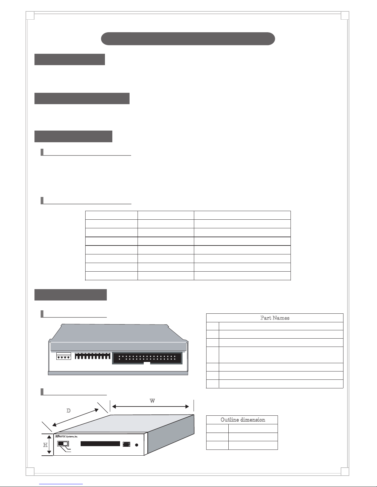
Part Names
4-2. Front part
4-1. Rear part
H
W
D
CompactFlash
REX-FDCF
Read/Write
Read Only
1 2 3 4 5 6 7 8 9 10
①
②
③
④
⑤
⑥
⑦
If the write-protect SW is turned to the "Read Only",
it returns the state "write-protect floppy media is inserted" to the host PC.
Power connector
Setting DIP-SW (Refer to section 4-4)
CF media slot
CF media eject button
CF media write-protect SW
CF media access LED
Part Names
①
②
③
④
⑤
⑥
⑦
FDD Interface connector (Refer to section 4-5)
Outline dimension
Width
Depth
Height
4.00in(101.50mm)
4.43in( 112.50mm)
0.99in( 25.30mm)
- 1 -
Page 2
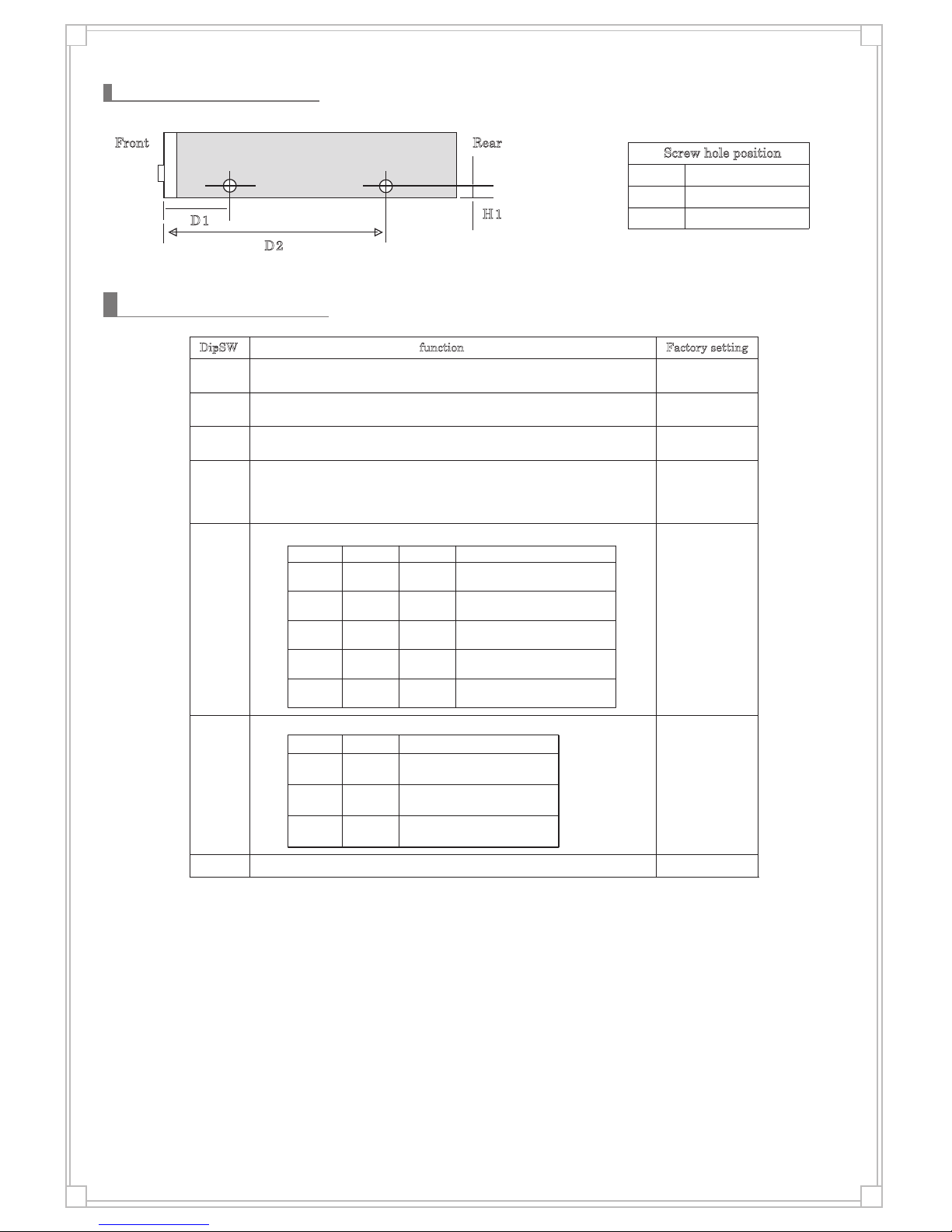
Setting DIP-SW
4-4
4-3. Screw hole position
▲
▲
▲
▲
▲
▲
D1
H1
D2
Front Rear
D1
H1
D2
Screw hole position
0.98in(25.00mm)
3.35in(85.00mm)
0.17in(4.20mm)
Dip-SW function
OFF2HD/2DD select
OFFDrive select
ON :2DD
OFF:2HD
OFFSelect drive mode
OFFMODE SELECT Logic invert
OFF
OFF
OFF
Select DISK CHANGE/READY output
2pin:HIGH DENSITY output
4pin:DISK CHANGE output
function
ON OFF
OFF ON
2pin:No output
4pin:HIGH DENSITY output
OFF OFF
2pin:No output
4pin:No output
Select HIGH DENSITY output pin
OFF
OFF
OFF
Reserved
2pin:Depend on No.8,9
34pin:DISK CHANGE output
function
OFF OFF OFF
ON ON OFF
2pin:DISK CHANGE output
34pin:No output
ON OFF ON
ON ON ON
2pin:DISK CHANGE output
34pin:READY output
ON OFF OFF
2pin:depend on No.8,9
34pin:No output
2pin:depend on No.8,9
34pin:READY output
Factory setting
No.10
No.1
No.2
No.3
No.4
No.5
No.6
No.7
No.8
No.9
No.5 No.6 No.7
No.8
No.9
ON : 2.0MB mode (Low level)
1.6MB mode (High level)
OFF: 2.0MB mode (High level)
1.6MB mode (Low level)
ON :2mode (2.0/1.0MB or 1.6/1.0MB)
OFF:3mode (2.0/1.6/1.0MB)
ON :A drive(DRIVE SELECT0 input mode)
OFF:B drive(DRIVE SELECT1input mode)
- 2 -
Page 3
RATOC Systems,Inc.
http//:www.ratocsystems.com/english/support
- 3 -
4-5
FD Interface connector
No.
4
HIGH DENSITY2
5
GND P
IPU
6
RESE RVED
7
GND P
Index hole signal
(Indicate sector start position)
OD
8
INDEX
9
GND P
drive select 1
IPU
10
DRIVE SELECT0
11
GND P
IPU
12
DRIVE SELECT1
13
GND P
IPU
14
RESE RVED
15
GND P
IPU
16
RESE RVED
17
GND P
IPU18 DIRECTION SELECT
19 GND
P
moving direction of magnetic head
20
STEP
21
GND P
IPU
22 WRITE DATA
23
GND
P
IPU
24
WRITE GATE
25
GND
P
OD
26
TRACK00
27
GND P
OD
28
WRITE PROTECT
29
GND P
OD
30
READ DATA
31
GND P
IPU
32
SIDE SELECT
33
GND P
OD
34
DISK CHANGE
READY
P
1
GND
ground KEY ※
Name explanation No. Name explanation
2
NC
3
KEY
B
IPU
P: Power /I :Input /O:Output / B : input/Output /OD :open drain/IPU :input (with PullUp )/NC : no connect
* Pin header of No.3 pin has been cut.
I/O I/O
IPU/OD
Select 2.0MB or 1.6MB mode
Indicate media removed
Select 2HD or 2DD mode
select 2HD or 2DD
IPU Unused on this equipment
magnetic head moving signal
( move 1 track by 1 pulse input)
Mode SELECT DISK
DISK CHANGE2
HIGH DENSITY
ground
ground
ground
ground
ground
ground
ground
ground
ground
ground
ground
Unused on this equipment
ground
ground
Unused on this equipment
Drive select 0
Unused on this equipment
Indicate media removed and ready state.
specify use sector side
Read data
Indicate media write protected
Indicate track head position track00
Writing data
ground
ground
ground
Writing data
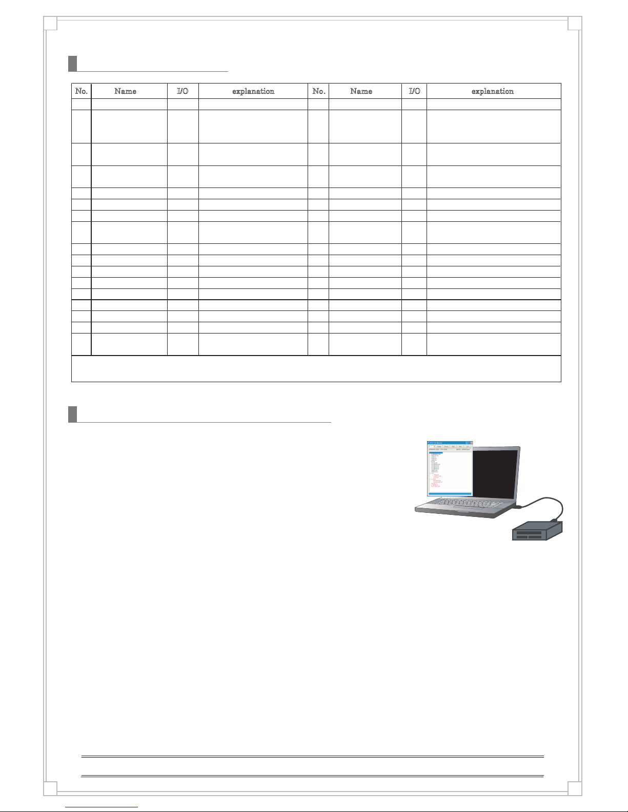
・The S/W gives you access to CF media(formatted by REX-FDCF) via USB.
・CF master disk for REX-FDCF can be created by using the S/W.
・CF media can be used with CF R/W that recognized as USB-MassStorageClass.
・Supports Windows8.1,8,7, Vista, XP (32bit/64bit)
・Supports FAT format
4-6 RSD-FDFM - File Manager (optional product)
 Loading...