

Rath 2500-12SPRVSR, 2500-16SPRVSR, 2500-28SPRVSR, 2500-36SPRVSR, 2500-56SPRVSR Installation & Operation Manual
...
Installation & Operations Manual
360° Supervision System
2500-12SPRVSR
2500-16SPRVSR
2500-28SPRVSR
2500-36SPRVSR
N56W24720 N. Corporate Circle Sussex, WI 53089
Made in the USA
2 Year Warranty
www.area-of-refuge.com www.rathmicrotech.com
2500-56SPRVSR
2500-76SPRVSR
2500-92SPRVSR
800-451-1460 262-246-4828 (fax)
RP8500SPRVSR
Ver. 3
10/17

Thank you for purchasing Rath’s 360° Supervision System. We are the largest Emergency Phone
Manufacturer in North America and have been in business for over 35 years.
We take great pride in our products, service, and support. Our Emergency Phones are of the highest
quality. Our experienced customer support teams are available to assist with site preparation, installation,
and maintenance. It is our sincere hope that your experience with us has and will continue to surpass
your expectations.
Thank you for your business,
Tom Touchett
Table of Contents
Installation . . . . . . . . . . . . . . . . . . . . . . . . Page 1-5
12-36 Zone Wiring Diagram . . . . . . . . . . Page 2
56-92 Zone Wiring Diagram . . . . . . . . . . Page 2
Typical System Wiring Diagram . . . . . . . Page 6
Installation & Wiring Instructions
1. Remove all materials from box.
2. Disconnect 2500 Supervisor Board from mounting bracket by removing the (4) screws from frame.
3. Using a 110 style punch tool, attach wiring pig-tails (supplied with Command Center) to the 2500
Supervisor Board according to wiring diagram for your system (see diagrams on page 2).
Page 1

Wiring For 12-36 Zone System:
NOTE: For 12-16 Zone Systems (1) 2500
Supervisor Board is included, for
28-36 Zone Systems (2) 2500
Supervisor Boards are included.
Wiring For 56-92 Zone System:
NOTE: For 56 Zone Systems (3) 2500 Supervisor
Boards are included, for 76 Zone Systems
(4) 2500 Supervisor Boards are included, and
for 92 Zone Systems (5) 2500 Supervisor
Boards are included.
Page 2
4. Secure the cables using provided cable ties.
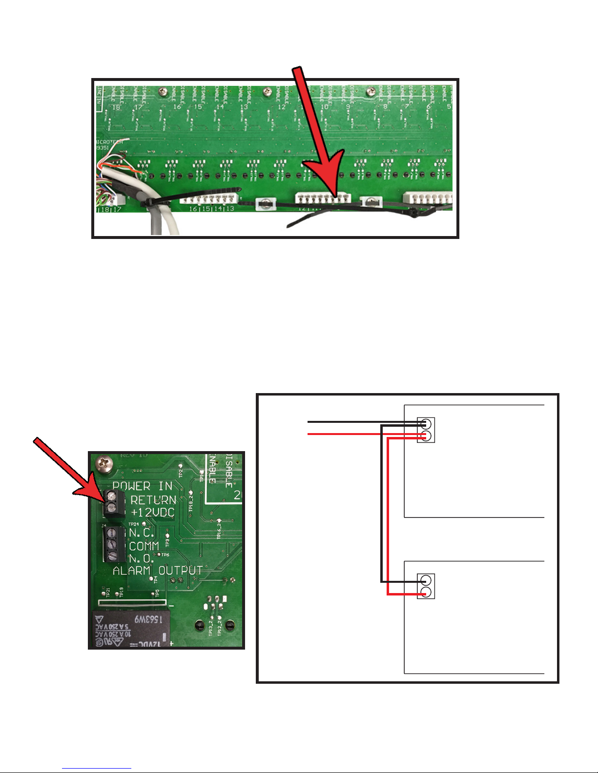
5. Attach supplied +12vdc Power Supply to appropriate terminals on 2500 Supervisor Board. Insert the
+ wire into the + connector and - wire into the RETURN connector on board and secure by screwing
down the capture clip. For systems larger than 16 zones, connect subsequent 2500 Supervisor
Boards in series by connecting an additional wire to the + and RETURN terminals for feeding power
to next board in system. Repeat as necessary to provide power to all boards.
12 VDC
POWER
SUPPLY
POWER IN
RETURN
+ 12VDC
SUPERVISORY BOARD 1
POWER IN
RETURN
+ 12VDC
SUPERVISORY BOARD 2
Page 3

6. Ensure switches for monitored ports are set to proper positions. The system comes from factory with
switches in “DISABLE” position. If port is to be monitored, slide switch to “ENABLE”. Switches on
positions 19 and 20 are for central ofce (telephone) lines, Base Station phone, or phones.
7. Ensure input switch for 19 and 20 reect the type of connection to be monitored.
8. Attach alert notication wiring (not provided) to Normally Open (NO) or Normally Closed (NC)
contacts of notication relay.
Page 4

9. Mount swing-mount bracket to wall using appropriate fasteners (skip this step if mounting
2500 Supervisor Board in 19” rack).
10. Attach 2500 Supervisor Board to mount using screws removed in step 2.
11. Plug feeder cables into Distribution Module.
12. Plug Base Station phone, phones, and telephone lines into appropriate RJ11 ports 1-20 on front
of 2500 Supervisor Board.
Note: Maximum distance from Supervisor Board to stations are 1000’ to Command Center
and 4000’ to endpoints.
13. Plug power transformer into UPS.
UPS
14. Ensure LEDs associated with Supervisor Ports 1-20 are out and green status light is lit.
Page 5

Typical System Wiring Diagram
Page 6
 Loading...