


Topaz, Stratus, Tropos,
Garnet, and Duros
PMC Graphics Boards
User’s Manual
Rastergraf
Rastergraf, Inc.
1810-J SE First St.
Redmond, OR 97756
(541) 923-5530
web: http://www.rastergraf.com
Release 3.7
May 7, 2017

Table of Contents
INTRODUCTION.......................................................................................................... 0-1
GETTING HELP .......................................................................................................................................... 0-2
BOARD REVISIONS .................................................................................................................................... 0-2
NOTICES .................................................................................................................................................... 0-3
CONVENTIONS USED IN THIS MANUAL ..................................................................................................... 0-4
CHAPTER 1 GENERAL INFORMATION .............................................................. 1-1
1.1 INTRODUCTION ................................................................................................................................... 1-2
1.2 SM731 GRAPHICS CONTROLLER ........................................................................................................ 1-9
1.2.1 Overview ................................................................................................................................. 1-9
1.2.2 Detailed Description.............................................................................................................. 1-10
1.2.3 SM731 Features..................................................................................................................... 1-11
1.3 VIDEO CAPTURE AND PLAYBACK ..................................................................................................... 1-13
1.4 BT835 NTSC/PAL/SECAM DIGITIZER ........................................................................................... 1-16
1.5 AD9882 RGBHV/DVI DIGITIZER .................................................................................................... 1-17
1.6 FLEXIBLE DISPLAY SUPPORT ............................................................................................................ 1-18
1.6.1 TV Display ............................................................................................................................ 1-19
1.6.2 Analog RGB Displays ........................................................................................................... 1-19
1.6.3 STANAG 3350 A-C (Topaz/Duros)...................................................................................... 1-19
1.6.4 Flat Panel Displays................................................................................................................ 1-20
1.7 FRONT AND REAR PANEL I/O OPTIONS............................................................................................. 1-22
1.8 SOFTWARE SUPPORT......................................................................................................................... 1-25
1.9 ADDITIONAL DETAILS ABOUT SDL .................................................................................................. 1-25
1.10 ADDITIONAL REFERENCES .............................................................................................................. 1-27
CHAPTER 2 SPECIFICATIONS ................................................................................ 2-1
2.1 GENERAL ............................................................................................................................................ 2-2
2.2 SPECIFICATIONS UNIQUE TO TOPAZ, STRATUS, AND GARNET ............................................................ 2-8
2.3 DISPLAY TIMING...............................................................................................................................2-10
2.4 MONITOR REQUIREMENTS ................................................................................................................ 2-12
2.5 VERIFIED DISPLAY AND CAPTURE MODES ....................................................................................... 2-13
2.5.1 Basic Format Evaluations...................................................................................................... 2-13
2.5.2 Maximum Display/Capture Performance.............................................................................. 2-15
2.6 CONFIGURATION INFORMATION ....................................................................................................... 2-17
2.6 SOFTWARE SUPPORT......................................................................................................................... 2-20
CHAPTER 3 CONNECTOR PINOUTS AND CABLE INFORMATION .............. 3-1
3.1 INTRODUCTION ................................................................................................................................... 3-2
3.2 VGA CONNECTOR .............................................................................................................................. 3-5
3.3 DVI-I CONNECTOR ............................................................................................................................. 3-7
3.4 MDR20 CONNECTOR.......................................................................................................................... 3-9
3.4.1 MDR20 Pinout 20A – NTSC/PAL or RGBHV In, NTSC/PAL Out....................................... 3-9
3.4.2 MDR20 Pinout 20B – DVI Input........................................................................................... 3-10
3.5 MDR26 CONNECTOR........................................................................................................................ 3-11
3.5.1 MDR26 Pinout 26A – Video In, Video Out, Ch 1 LVDS Out.............................................. 3-11
3.5.2 MDR26 Pinout 26B – DVI Input, Ch 1 LVDS Out............................................................... 3-12
3.5.3 MDR26 Pinout 26C – Ch 1 and CH 2 LVDS Out................................................................. 3-12
3.6 MDSM CONNECTOR......................................................................................................................... 3-13
3.6.1 Pinout MDSMA – NTSC/PAL or RGBHV In, NTSC/PAL Out........................................... 3-13

3.6.2 Pinout MDSMB – DVI Input ................................................................................................3-14
3.7 S-VIDEO CONNECTOR....................................................................................................................... 3-15
3.8 VGA TO VGA CABLE....................................................................................................................... 3-16
3.9 S-VIDEO ADAPTER CABLES .............................................................................................................. 3-17
3.10 DVI-I MULTIFUNCTION BREAKOUT CABLE .................................................................................... 3-19
3.10.1 C1 – Primary VGA.............................................................................................................. 3-20
3.10.2 C2 – Secondary VGA.......................................................................................................... 3-20
3.10.3 C3 – DVI ............................................................................................................................. 3-21
3.11 DVI-I TO VGA ADAPTERS.............................................................................................................. 3-22
3.12 TOPAZPMC VGA BREAKOUT CABLE............................................................................................. 3-24
3.13 TOPAZPMC VIDEO I/O BREAKOUT CABLE..................................................................................... 3-25
3.14 TOPAZPMC DVI IN ADAPTER CABLE ............................................................................................ 3-26
3.15 TOPAZPMC VIDEO I/O + LVDS BREAKOUT CABLE ...................................................................... 3-27
3.16 TOPAZPMC DVI IN + LVDS BREAKOUT CABLE............................................................................ 3-28
3.17 TOPAZPMC LVDS EXTENSION CABLE .......................................................................................... 3-29
3.18 STRATUSPMC VIDEO I/O BREAKOUT CABLE................................................................................. 3-31
3.19 STRATUSPMC DVI IN ADAPTER CABLE ........................................................................................ 3-32
3.20 CONNECTIONS TO PMC PN1, PN2, AND PN4................................................................................... 3-33
Pn4 Connectors................................................................................................................................ 3-33
3.20.1 Pn1 Connector (all boards).................................................................................................. 3-35
3.20.2 Pn2 Connector (all boards).................................................................................................. 3-36
3.20.3 Pn4 – Dual LVDS Only....................................................................................................... 3-37
3.20.4 Pn4 – Dual LVDS and DVI (In or Out)............................................................................... 3-38
3.20.5 Pn4 - Dual LVDS, DVI (In or Out), Analog Video I/O, VGA............................................ 3-39
3.20.6 Pn4 - Dual LVDS, Dual VGA, Analog Video I/O .............................................................. 3-40
3.20.7 Pn4 - Dual LVDS, VGA, DVI In, DVI Out ........................................................................ 3-41
3.20.8 Pn4 - Dual LVDS, Dual VGA, DVI In................................................................................ 3-42
3.20.9 Pn4 - Dual LVDS, Single VGA........................................................................................... 3-43
3.20.10 Pn4 – RG-101 Compatible VGA Pinout............................................................................ 3-44
CHAPTER 4 INSTALLING YOUR RASTERGRAF GRAPHICS BOARD.......... 4-1
4.1 INTRODUCTION ................................................................................................................................... 4-2
4.2 UNPACKING YOUR BOARD ................................................................................................................. 4-2
4.3 PREPARING FOR INSTALLATION .......................................................................................................... 4-3
4.3.1 Interrupt Settings ..................................................................................................................... 4-3
4.3.2 Address Settings...................................................................................................................... 4-3
4.3.3 Changing the Jumpers ............................................................................................................. 4-3
4.4 GRAPHICS BOARD INSTALLATION.................................................................................................... 4-10
4.5 INSTALLING IN A PCI BACKPLANE USING A CARRIER ....................................................................... 4-14
4.6 INSTALLING IN A COMPACTPCI BACKPLANE USING A CARRIER ....................................................... 4-17
4.7 FINISHING THE INSTALLATION .......................................................................................................... 4-21
4.7.1 Connecting to the Monitor..................................................................................................... 4-21
4.7.2 Checking your Display.......................................................................................................... 4-22
4.8 USING A RASTERGRAF BOARD IN A PC............................................................................................. 4-23
4.8.1 Single Graphics Board........................................................................................................... 4-23
4.8.2 Multiboard Operation ............................................................................................................ 4-23
4.9 USING A RASTERGRAF BOARD IN A POWERPC ................................................................................. 4-28
4.10 FINAL CHECKS................................................................................................................................ 4-28
CHAPTER 5 PROGRAMMING ON-BOARD DEVICES AND MEMORIES...... 5-1
5.1 INTRODUCTION ................................................................................................................................... 5-2
5.2 SM731 GRAPHICS ACCELERATOR ...................................................................................................... 5-3
5.3 CLOCKS............................................................................................................................................ 5-12
5.3.1 CY22150 Reference Clock.................................................................................................... 5-12
5.4 VIDEO TIMING PARAMETERS ............................................................................................................ 5-13

5.4.1 Application Note: Adjusting the Timing Parameters............................................................. 5-14
5.4.2 Pan and Scroll........................................................................................................................ 5-17
Request for Assistance in Determining Video Timing Parameters ................................................. 5-18
5.5 SYSTEM MANAGEMENT DEVICES AND FUNCTIONS........................................................................... 5-19
5.6 TALK TO ME THROUGH I2C.............................................................................................................. 5-20
5.7 TOPAZ/STRATUS/GARNET AUXILIARY REGISTER ............................................................................. 5-21
5.8 DVI DIGITAL VIDEO OUTPUT ........................................................................................................... 5-22
5.9 ADV7123 AND ADV7120 VGA DACS............................................................................................ 5-24
5.10 AD9882 HIGH SPEED DIGITIZER (STRATUS/GARNET) .................................................................... 5-25
5.11 BT835 NTSC/PAL/SECAM VIDEO DECODER ............................................................................... 5-26
5.12 FLASH EEPROM ............................................................................................................................ 5-30
5.13 SERIAL EEPROM........................................................................................................................... 5-31
5.14 INTERRUPTS .................................................................................................................................... 5-31
CHAPTER 6 TROUBLESHOOTING........................................................................ 6-1
6.1 GENERAL PROCEDURES ...................................................................................................................... 6-2
6.2 DEALING WITH THE PCI BUS .............................................................................................................. 6-3
6.3 MAINTENANCE, WARRANTY, AND SERVICE ....................................................................................... 6-3

Tables
Table 1-1 Board Feature Summary................................................................................. 1-3
Table 1-2 SDL Functional Summary............................................................................1-26
Table 2-1 Rastergraf Ruggedization Levels Chart.......................................................... 2-7
Table 2-2 BIOS Display Timing Specifications ........................................................... 2-10
Table 2-3 VGA/Windows Platform Display Timing Specifications ........................... 2-10
Table 2-4 SDL Platform Display Timing Specifications............................................. 2-11
Table 2-5 Basic Display/Capture Format Capabilities ................................................ 2-14
Table 2-6 Maximum Display/Capture Format Capabilities.........................................2-16
Table 2-7 Standard Front Panel Board Configurations and Connector Utilization..... 2-18
Table 2-8 Standard Rear Panel Board Configurations and I/O Assignments..............2-19
Table 2-9 Front Panel Board Model Compatibility ..................................................... 2-19
Table 2-10 Software...................................................................................................... 2-20
Table 3-1 Front Panel Signal Definitions ....................................................................... 3-3
Table 3-2 Front and Rear Panel Connector Usage.......................................................... 3-4
Table 3-3 Analog (VGA) Video Connector Pinout ........................................................ 3-6
Table 3-4 Tropos DVI-I Connector (Pinout D1) ............................................................ 3-7
Table 3-5 TopazPMC/2 and StratusPMC DVI-I Connector (Pinout D2)....................... 3-8
Table 3-6 Video I/O (VI/O) Front Panel Connector (Pinouts 20A & 20B).................... 3-9
Table 3-7 Video I/O (VI/O) Front Panel Connector (Pinouts 26A-26C) .....................3-11
Table 3-8 Video I/O (VI/O) Front Panel Connector (Pinouts MDSMA & MDSMB) . 3-13
Table 3-9 VGA to VGA Cable (A31-00599-1012) ...................................................... 3-16
Table 3-10 TopazPMC S-Video to BNC adapter cable (A31-00709-1003)................. 3-17
Table 3-11 StratusPMC BNC to S-Video Adapter Cable (VAD44) ............................ 3-18
Table 3-12 C1 - Primary VGA Connector....................................................................3-20
Table 3-13 C2 - Secondary VGA Connector................................................................3-20
Table 3-14 C3 - DVI-D Connector ............................................................................... 3-21
Table 3-15 DVI-I to VGA Adapter............................................................................... 3-22
Table 3-16 TopazPMC VGA Breakout Connector....................................................... 3-24
Table 3-17 TopazPMC Video I/O Breakout Cable....................................................... 3-25
Table 3-18 TopazPMC DVI In Adapter Cable ............................................................. 3-26
Table 3-19 TopazPMC Video I/O + LVDS Breakout Cable........................................3-27
Table 3-20 TopazPMC DVI In + LVDS Breakout Cable ............................................3-28
Table 3-21 TopazPMC LVDS Extension Cable (A31-00735-4012)............................ 3-30
Table 3-22 StratusPMC Video I/O Breakout Cable (A31-00735-0036) ...................... 3-31
Table 3-23 StratusPMC DVI In Adapter Cable............................................................3-32
Table 3-24 Rear Panel Signal Definitions ....................................................................3-34
Table 4-1 x86 Supported Video Modes........................................................................ 4-24
Table 5-1 Standard Graphics Display Formats.............................................................5-13

Table 5-2 Video Timing Parameter Request Form...................................................... 5-18
Table 5-3 I2C Device Addresses................................................................................... 5-20
Figures
Figure 1-1 Topaz Block Diagram ................................................................................... 1-4
Figure 1-2 Stratus Block Diagram .................................................................................. 1-5
Figure 1-3 Tropos Block Diagram..................................................................................1-6
Figure 1-4 Garnet Block Diagram .................................................................................. 1-7
Figure 1-5 Duros Block Diagram ..................................................................................1-8
Figure 1-6 SM731 Application Block Diagram.............................................................. 1-9
Figure 1-7 SM731 Detail Block Diagram..................................................................... 1-12
Figure 1-8 Video Capture and Playback Support ......................................................... 1-13
Figure 1-9 Capture Buffer and Display Memory.......................................................... 1-14
Figure 1-10 Video Processing Data Path...................................................................... 1-15
Figure 1-11 Bt835 Video Digitizer Block Diagram .....................................................1-16
Figure 1-12 AD9882 High Speed Digitizer Block Diagram ........................................1-17
Figure 1-13 Display Channels ......................................................................................1-18
Figure 1-14 DVI Flat Panel Output Block Diagram.....................................................1-20
Figure 1-15 LVDS Flat Panel Output Block Diagram.................................................. 1-21
Figure 1-16 Front and Rear Panel I/O Options for Topaz ............................................ 1-22
Figure 1-17 Front and Rear Panel I/O Options for Stratus ........................................... 1-23
Figure 1-18 Front and Rear Panel Output Options for Tropos ..................................... 1-23
Figure 1-19 Rear Panel I/O Options for Garnet............................................................ 1-24
Figure 1-20 Rear Panel Output Options for Duros ....................................................... 1-24
Figure 3-1 S-Video Connector...................................................................................... 3-15
Figure 3-2 VGA to VGA Extension Cable (A31-00599-1012)....................................3-16
Figure 3-3 S-Video to BNC Adapter (A31-00709-1003)............................................. 3-17
Figure 3-4 BNC to S-Video Adapter Cable (VAD44).................................................. 3-18
Figure 3-5 DVI-I Multifunction Breakout Cable (A31-00735-1012)........................... 3-19
Figure 3-6 Molex 88741-8700 DVI-I to VGA Adapter................................................ 3-22
Figure 3-7 DVI to VGA Adapter Cable (A31-00599-5012) ........................................3-23
Figure 3-8 TopazPMC VGA Breakput Cable (A31-00735-2012) ...............................3-24
Figure 3-9 TopazPMC LVDS Extension Cable (A31-00735-4012) ............................3-29
Figure 3-10 MDSM to BNC Breakout Cable (A31-00735-0036)................................ 3-31
Figure 4-1 Jumper Locations for the Fab Rev 0 TopazPMC Board............................... 4-5
Figure 4-2 Jumper Locations for the Fab Rev 1 TopazPMC Board............................... 4-5
Figure 4-2 Jumper Locations for the Fab Rev 1 TopazPMC Board............................... 4-6
Figure 4-3 Jumper Locations for the Fab Rev 2 TopazPMC Board............................... 4-7

Figure 4-4 Jumper Locations for the Fab Rev 1 StratusPMC and TroposPMC Boards. 4-7
Figure 4-4 Jumper Locations for the Fab Rev 1 StratusPMC and TroposPMC Boards. 4-8
Figure 4-5 Jumper Locations for the Fab Rev 1 Garnet and Duros Boards ...................4-9
Figure 4-6 Installation of a PMC Module into an Emerson MVME2604 .................... 4-12
Figure 4-7 Installation of the PMC Module into an Emerson CPV3060...................... 4-13
Figure 4-8 Installation of a PMC Module onto a PCI-PMC Carrier............................. 4-15
Figure 4-9 Installation of a PCI Module into an Emerson MTX..................................4-16
Figure 4-10 Installation of a PMC Module onto a 3U CPCI- PMC Carrier................. 4-18
Figure 4-11 Installation of a PMC Module into a 6U CPCI- PMC Carrier..................4-19
Figure 4-12 Installing a CompactPCI Board ................................................................4-20
Figure 5-1 CY22150 Block Diagram............................................................................ 5-12
Figure 5-2 Video Display Timing Fields......................................................................5-15
Figure 5-3 THC63DV164 Block Diagram ...................................................................5-22
Figure 5-4 THC63DV164 RGB to 24-bit TMDS Mapping Diagram........................... 5-23
Figure 5-5 Bt835 Detailed Block Diagram...................................................................5-27


Rastergraf
Introduction
This manual provides information about how to configure, install, and
program the Rastergraf Silicon Motion SM731-based Topaz, Stratus,
Tropos, Garnet, and Duros PMC graphics display controllers. When used
with appropriate PMC-to-host adapters, PCI and CompactPCI compatible
computers can also be supported.
This manual is broken down into six chapters:
Chapter 1: General Information
Chapter 2: Specifications
Chapter 3: Connector Pinouts and Cable Information
Chapter 4: Installing Your Graphics Board
Chapter 5: Programming Devices and Memories
Chapter 6: Troubleshooting
Chapters 1-3 provide background material about the graphics boards.
Understanding the information in the chapters, however, is not essential
for the hardware or software installation. If you want to perform the
installation as quickly as possible, start with Chapter 4. If you have
problems installing the hardware, refer to Chapter 6 for help.
Introduction - 1

Rastergraf
Getting Help
This installation manual gives specific steps to take to install your
Rastergraf board. There are, however, variables specific to your computer
configuration and monitor that this manual cannot address. Normally, the
default values given in this manual will work. If you have trouble
installing or configuring your system, first read Chapter 6,
“Troubleshooting”. If this information does not enable you to solve your
problems, do one of the following:
1) call Rastergraf technical support at: (541) 923-5530
2) send E-mail to: support@rastergraf.com
If your problem is monitor related, Rastergraf technical support will need
detailed information about your monitor.
Board Revisions
This manual applies to the following board revision levels:
Tropos/Stratus Fab Rev 1
Duros/Garnet Fab Rev 1
Topaz Fab Rev 0, 1, 2
Manual Revisions
Revision 3.1 April 2007 Rastergraf version
Revision 3.2 September 2007 Update RIO info
Revision 3.3 February 12, 2008 Fix part numbers, add
Revision 3.4 December 6, 2013 Changes for Topaz Rev 1.
Revision 3.5 January 6, 2014 clean up some text in Ch. 3
Revision 3.6 February 7, 2017 clean up and correct tables in
Revision 3.7 May 5, 2017 Changes for Topaz Rev 2.
.
LVDS info, change cable info.
Remove fax, update address, add
RG-101 pinout
Section 3.20.
Moved jumpers, added option for
VGA Ch 2 on Ch 1 on DVI-I
Introduction - 2

Notices
Rastergraf
Information contained in this manual is disclosed in confidence and may
not be duplicated in full or in part by any person without prior approval of
Rastergraf. Its sole purpose is to provide the user with adequately detailed
documentation to effectively install and operate the equipment supplied.
The use of this document for any other purpose is specifically prohibited
The information in this document is subject to change without notice. The
specifications of the graphics boards and other components described in
this manual are subject to change without notice. Although it regrets them,
Rastergraf, Inc. assumes no responsibility for any errors or omissions that
may occur in this manual. Customers are advised to verify all information
contained in this document
The electronic equipment described herein generates, uses, and may
radiate radio frequency energy, which can cause radio interference.
Rastergraf, Inc. assumes no liability for any damages caused by such
interference.
Rastergraf, Inc.’s products are not authorized for any use as critical
components in flight safety or life support equipment without the express
consent of the president of Rastergraf, Inc.
These products have been designed to operate in user-provided PMCcompatible computers. Connection of incompatible hardware is likely to
cause serious damage. Rastergraf assumes no liability for any damages
caused by such incompatibility.
Rastergraf assumes no responsibility for the use or reliability of software
or hardware that is not supplied by Rastergraf, or which has not been
installed in accordance with this manual.
The TopazPMC, StratusPMC, TroposPMC, GarnetPMC, and DurosPMC
graphics boards are manufactured and sold under license from
Curtiss-Wright Controls Embedded Computing (CWCEC). Contact
Rastergraf, Inc. for additional information.
Rastergraf is a trademark of Rastergraf, Inc.
All other trademarks and copyrights are the property of their respective
owners.
Copyright © 2017 by Rastergraf, Inc.
Introduction - 3

Rastergraf
Conventions Used In This Manual
The following list summarizes the conventions used throughout this
manual.
Code
fragments
Commands or
program names
System prompts
and commands
Keyboard usage
Note
Caution
Code fragments, file, directory or path names and
user/computer dialogs in the manual are presented
in the courier typeface.
Commands, or the names of executable programs,
except those in code fragments, are in bold.
Commands in code fragments are preceded by the
system prompt, a percentage sign (%), the standard
prompt in UNIX’s C shell, or the hash mark (#),
the standard UNIX prompt for the Super-User.
<CR> stands for the key on your keyboard labeled
“RETURN” or “ENTER”
Note boxes contain information either specific to
one or more platforms, or interesting, background
information that is not essential to the installation.
Caution boxes warn you about actions that can
cause damage to your computer or its software.
Warning!
Introduction - 4
Warning! boxes warn you about actions that can
cause bodily or emotional harm.

Chapter 1
General Information
Rastergraf
General Information 1-1

Rastergraf
1.1 Introduction
The Topaz, Stratus, Tropos, Garnet, and Duros comprise a set of closely
related designs that have been tuned to address a variety of requirements.
Originally starting with the Stratus as the fully configured version and
Tropos as the low parts count version, the line was expanded into the
analogous Garnet and Duros which are rugged, conduction cooled
versions adding 2 thermal layers and, on the Duros, the ability to produce
STANAG 3350 A-C output modes.
The final iteration is the Topaz, a non-conduction cooled design, which is
intended to subsume the Stratus and Tropos. It:
a) includes the new features added in the Garnet and Duros,
b) using an MDR26 connector, adds the optional capability to provide
LVDS on the front panel,
c) replaces the Stratus front panel MDSM Video I/O connector with an
MDR20 for easier cable construction,
d) adds a dual front panel VGA connector option,
e) adds the 3.3V local regulator option that was dropped on Garnet and
Duros.
The following page shows a table of the features of the boards in a
comparative format to ease understanding what each version provides.
Following that are block diagrams of each board, and then some
explanatory sections covering the board functions.
1-2 General Information

Table 1-1 Board Feature Summary
Rastergraf
Topaz
Stratus/
Garnet
Tropos/
Duros
Silicon Motion SM731 2D/3D engine with 16MB SDRAM yes yes yes
1600x1200 single VGA
1024x768 dual VGA
1280x1024 single/1024x768 dual LVDS
1600x1200 single DVI
yes yes yes
yes
yes
no
yes yes yes
yes yes option
S-Video/NTSC/PAL/SECAM single output yes yes Duros
Interlaced/non-interlaced, Sync-On-Green
STANAG 3350 A-C output option
DVI Input mode yes
RGBHV, RGB, and STANAG Input modes yes
S-Video/NTSC/PAL/SECAM Input modes yes
yes yes Duros
yes
no Duros
yes no
yes no
yes no
Dual front panel VGA connector option yes no no
Dual VGA via DVI b/o cable option yes
Dual VGA rear panel option yes yes
Stratus
no
no
LVDS options – front/rear yes rear only rear only
MDR26 LVDS front panel connector option yes
n/a n/a
Single DVI options – front/rear yes yes yes
Composite/S-Video output
MDSM-16 Video I/O connector no
yes yes yes
Stratus
no
MDR20 Video I/O connector yes no no
2 Kb serial EEPROM and LM75 thermal sensor
yes yes yes
3.3V & 5V PCI Bus Signaling yes yes yes
33/66 MHz PCI Bus Speed yes yes yes
CCPMC form factor compatible yes yes yes
Full CCPMC version with thermal layers no
Local 3.3V regulator yes
Garnet Duros
Stratus Tropos
Side 1 only component loading yes yes yes
Field reprogrammable VGA BIOS yes yes yes
SDL Graphics Subroutine Package
SDL-based WindML and BIT
Windows 2K/XP graphics drivers
Windows 2K/XP video input drivers
Xfree86 Version 4.3 for Linux and VxWorks
X video in extensions for Linux and VxWorks
RG-101 Rear I/O compatible version (PCB Rev 1)
yes yes yes
yes yes yes
yes yes yes
yes yes no
yes yes yes
yes yes no
yes no no
General Information 1-3

Rastergraf
Figure 1-1 Topaz Block Diagram
Front
Front
Front
Front
Panel
Panel
Panel
Panel
Version
Version
Version
Version
Rear
4
3
2
1
Panel
RGB In
Analog Devices
Out
VGA
VGA Ch 1
Connector
Out
VGA
VGA Ch 1
Connector
Out
VGA
VGA Ch 1
Connector
Out
DVI-I
VGA Ch 1
Connector
Out
Graphics
VGA Ch 1
DVI In
Select
Conexant Bt835
RGB/DVI Digitizer
AD9882 High Speed
Video In
Processor
Video Input
VGA
Connector
Graphics
VGA Ch 1 Out
Out
VGA Ch 2
Out
VGA Ch 2
Out
Graphics
VGA Ch 2
DVI Out
Analog Devices
THine THC63DV164
DVI Output Encoder
ADV7120 DAC (STANAG)
LVDS
Single
MDR-26
Channel
Connector
Dual
Channel
Connector
Dual
Graphics
LVDS
Channel
MDR-26
DVI Out
DVI
I/O Resource Manager
Video Out
VGA Ch 2 Out
ADV7123 DAC
Analog Devices
LVDS
MDR-20
Connector
LVDS Out
Video
Input/
Output/
Video
Input/
Output/
Video
Input/
Important Note
Topaz can support
or
DVI In
RGBHV
or
DVI In
RGBHV
or
Output/
DVI In
RGBHV
OR
Video Input
STANAG Out
RGB/DVI/NTSC/PAL
but not at the same time
Figure 1-1 Topaz Block Diagram
Ch 1
Ch 2
C
2
I
Controller
SM731
Motion
Silicon
Graphics
1-4 General Information
Input
Video
Processor
On-Chip
Accelerator
YUV/RGB Multiplexer
PLD for STANAG or
235 MHz
RAMDAC
Video
Display
Memory
Output
Processor
Drivers
Flat Panel
PCI Bus
32 bit
33/66 MHz
Interface
PMC (PCI) Bus
Video
NTSC/PAL
2D/3D
Drawing
Encoder
Engines
Dual
Channel
DMA
LVDS
Encoder
Engine
PLD Controller
BIOS EEPROM
BIOS
Memory
Interface
3.3V
Local
Regulator
Option

Rastergraf
Figure 1-2 Stratus Block Diagram
Front
Panel
Rear
Panel
Option
Option
RGB In
Analog Devices
AD9882 High Speed
Out
DVI-I
VGA Ch 1
Connector
Out
Graphics
VGA Ch 1
DVI In
Select
Video In
Video Input
RGB/DVI Digitizer
Conexant Bt835
Graphics
VGA Ch 1 Out
Processor
Out
VGA Ch 2
Out
Graphics
VGA Ch 2
DVI Out
THine THC63DV164
DVI Output Encoder
DVI Out
DVI
Dual
Graphics
LVDS
Channel
I/O Resource Manager
Video Out
VGA Ch 2 Out
ADV7123 DAC
Analog Devices
MDSM
Connector
LVDS Out
Video
Video
Input/
Output/
Input/
Output/
or
RGBHV
or
RGBHV
DVI In
DVI In
Ch 1
Ch 2
C
2
I
Motion
Silicon
Controller
SM731
Graphics
Accelerator
Video
Input
Multiplexer
PLD for YUV/RGB
Processor
Display
Memory
On-Chip
235 MHz
RAMDAC
Video
Output
Processor
Drivers
Flat Panel
PCI Bus
Interface
32 bit
33/66 MHz
Video
Encoder
NTSC/PAL
2D/3D
Engines
Drawing
PMC (PCI) Bus
Dual
LVDS
Channel
DMA
Encoder
Engine
PLD Controller
BIOS
Memory
Local
BIOS EEPROM
Interface
3.3V
Regulator
Figure 1-2 Stratus Block Diagram
Option
General Information 1-5

Rastergraf
Figure 1-3 Tropos Block Diagram
Front
Panel
Rear
Panel
Option
Option
DVI-I
Connector
Graphics
Out
VGA Ch 1
Out
VGA Ch 1
Graphics
VGA Ch 1 Out
Out
VGA Ch 2
Out
VGA Ch 2
Graphics
DVI Out
THine THC63DV164
DVI Output Encoder
DVI Out
DVI
Dual
Channel
Graphics
LVDS
I/O Resource Manager
Video Out
VGA Ch 2 Out
ADV7123 DAC
Analog Devices
LVDS Out
Ch 1
Ch 2
C
2
I
Controller
SM731
Motion
Silicon
Graphics
Accelerator
1-6 General Information
Video
Input
Processor
Display
Memory
On-Chip
235 MHz
RAMDAC
Video
Output
Processor
Drivers
Flat Panel
PCI Bus
32 bit
33/66 MHz
NTSC/PAL
2D/3D
Interface
PMC (PCI) Bus
Video
Encoder
Engines
Drawing
Dual
LVDS
Channel
DMA
Encoder
Engine
PLD Controller
BIOS
Memory
Local
BIOS EEPROM
Interface
3.3V
Regulator
Figure 1-3 Tropos Block Diagram
Option

Rastergraf
Figure 1-4 Garnet Block Diagram
Ch 1
Rear
Ch 2
Panel
Graphics
DVI In
RGB In
Select
Analog Devices
RGB/DVI Digitizer
AD9882 High Speed
Out
VGA Ch 1
Video In
VGA Ch 1 Out
Processor
Video Input
Conexant Bt835
YUV/RGB Multiplexer
PLD for
Graphics
VGA Ch 2
Out
DVI
Graphics
DVI Out
VGA Ch 2 Out
Analog Devices
THine THC63DV164
DVI Output Encoder
Dual
LVDS
Channel
Graphics
I/O Resource Manager
Video Out
ADV7120 DAC
LVDS Out
Video
Input/
Output/
RGBHV
PLD Controller
or
DVI In
BIOS EEPROM
Figure 1-4 Garnet Block Diagram
C
2
I
Controller
SM731
Motion
Silicon
Video
Graphics
Accelerator
Input
Processor
Display
On-Chip
235 MHz
Memory
RAMDAC
Video
Output
Processor
Drivers
Flat Panel
PCI Bus
Interface
32 bit
33/66 MHz
Video
Encoder
NTSC/PAL
2D/3D
Engines
Drawing
PMC (PCI) Bus
Dual
LVDS
Channel
DMA
Encoder
Engine
BIOS
Memory
Interface
General Information 1-7

Rastergraf
Rear
Panel
Out
Graphics
VGA Ch 1
Figure 1-5 Duros Block Diagram
Out
Graphics
VGA Ch 2
DVI
Graphics
Dual
Graphics
LVDS
Channel
I/O Resource Manager
DVI Out
VGA Ch 1 Out
VGA Ch 2 Out
or
ADV7120 DAC
Analog Devices
STANAG >> VGA Ch 1
Second VGA >> VGA Ch 2
Video Out
THine THC63DV164
DVI Output Encoder
LVDS Out
Ch 1
Ch 2
C
2
I
Motion
Silicon
Controller
SM731
Graphics
Accelerator
Video
Input
PLD for STANAG
Processor
Display
Memory
On-Chip
235 MHz
RAMDAC
Video
Output
Processor
Drivers
Flat Panel
PCI Bus
32 bit
33/66 MHz
NTSC/PAL
2D/3D
Interface
PMC (PCI) Bus
Video
Encoder
Engines
Drawing
Dual
LVDS
Channel
DMA
Encoder
Engine
PLD Controller
BIOS
Memory
BIOS EEPROM
Interface
Figure 1-5 Duros Block Diagram
1-8 General Information

ZV Port
LaserDisc
NTSC/PAL
Decoder
TV Tuner
NTSC/PAL Camera
CRT Monitor
Flat Panel
PCI/AGP2X/4X
SM731
16/32MB
VCR or
MEMORY
DDR/SGRAM
8/16/32MB
TV
Optional
ZV Port
LaserDisc
NTSC/PAL
Decoder
TV Tuner
NTSC/PAL Camera
CRT Monitor
Flat Panel
PCI/AGP2X/4XPCI/AGP2X/4X
SM731
16/32MB
SM731
16/32MB
VCR or
MEMORY
DDR/SGRAM
8/16/32MB
MEMORY
DDR/SGRAM
8/16/32MB
MEMORY
DDR/SGRAM
8/16/32MB
MEMORY
DDR/SGRAM
8/16/32MB
TV
Optional
33/66 MHz, 32-bit PCI Bus
1.2 SM731 Graphics Controller
1.2.1 Overview
The SM731 is a low power 2D/3D display controller with 90, 180, and
270 degree hardware rotation. Silicon Motion's ReduceOn™ technology
for the SM731 implements functions in hardware that were previously
performed in software, allowing easier driver development. ReduceOn
technology intelligently monitors the activity on the device and optimizes
the power as necessary to maximize performance and power consumption.
This level of power management is possible since each functional block
and engine clock can be dynamically controlled to actively reduce the
overall power consumption.
Figure 1-6 SM731 Application Block Diagram
Rastergraf
33/66 MHz, 32-bit PCI Bus
16 MB
General Information 1-9

Rastergraf
1.2.2 Detailed Description
The SM731 delivers full-featured 3D, a unique memory architecture
designed to enhance 3D/2D performance, enhanced multi-display
capabilities, and Motion Compensation for DVD. Software support is
available under Windows 2K/XP and Linux/XFree86.
A robust 128-bit Drawing Engine provides excellent 2D performance. The
Drawing Engine supports 3 ROPs, BitBLT, transparent BLT, pattern BLT,
color expansion, line draw and Alpha blending. The Host interface Unit
allows support for PCI up to 66 MHz.
The SM731 incorporates an IEEE Floating Point Setup engine as well as a
full-featured 3D rendering engine. The 3D engine pipeline was designed
to operate in a balanced manner, allowing setup of 6 million triangles per
second (125MHz core frequency) and rasterization of 125 Mpix/s. The
dual pipe Texture engine can output 250 million Texels per second.
Among other features, SM731 natively supports MIP mapping, Alpha
blend, Specular highlights and Fog, Stencil planes, W buffer and fog,
Bump Mapping, and Z engine.
The SM731 integrates 16 Mbytes of on-board SGRAM (SDR) over a 64bit memory bus operating at up to 150 MHz. The 1.2 GB/sec peak
bandwidth available allows concurrent support of large displays and other
processing functions at optimum performance.
SM731 can drive two independent digital displays or simultaneously drive
LCD, CRT and TV displays. It also incorporates two 112 MHz Max pix
clock LVDS channels that can drive two separate panels or a single
high-resolution panel (up to UXGA). Support for all ACPI power states is
provided. A high quality TV encoder, VGA Core, LCD Backend
Controller and 235 MHz RAMDAC are incorporated as well.
The SM731's Motion Compensation block, Video Processor block, and
Video Capture Unit provide superior video quality for real-time video
playback and capture. When combined with performance CPUs, the
Motion Compensation block allows full frame playback of DVD video
content without the need for additional hardware. The Video Processor
supports multiple independent full screen, full motion video windows with
overlay. Each motion video window uses hardware YUV-to-RGB
conversion, scaling, and color interpolation. When combined with multiview capabilities of the chip, these independent video streams can be
output to each of two display devices and bilinear scaled to support
applications such as full screen display of local and remote images.
1-10 General Information

1.2.3 SM731 Features
High Performance Hardware Graphics Support
• 128-bit single-cycle graphics engine
• 16MB on-chip frame buffer memory with 128-bit interface
• IEEE Floating point setup engine
• Bi-linear/Tri-linear filtering, MIP-mapping, vertex and global fog
• Multi-texture, bump mapping, texture compression
• Source/destination alpha blending, Specular highlights
• Z-buffering, dual-texture pipelines
• BitBLT, line draw, Polygon/rectangle fill
• Hardware cursor and pop-up icons
Analog RGB Display Support
• 640 x 480 to 1600 x 1200 non-interlaced at 8, 16 or 24 bits/pixel
• Integrated NTSC/PAL video formats
• Composite and S-Video (Y/C) signal interfaces
Panel Support
• Integrated Dual Channel LVDS transmitters with DualMon support
• QuickRotate feature for instantaneous rotation
On-Chip Dual Display Support
• RGB+VIDEO (NTSC/PAL). LVDS+RGB (VGA)
LVDS+LVDS, and LVDS+VIDEO
Rastergraf
Video Capture and Playback Support
• Zoom video port with live video display or single-frame capture
• Full-screen video or in a window with or without graphics overlay
• Video window may be of arbitrary size and on any pixel boundary
• Multiple independent hardware video windows
• Independent video capture and display subsystems
• Arbitrary XY scaling and up to 8x zoom on video input stream
• YUV capture data directly from host using on-chip DMA controller
• Motion compensation for full-speed DVD playback
PCI Bus
• 32-bit 33/66 MHz PCI 2.1 interface with burst-mode capability
• 264 Mbytes/sec peak data transfer rate at 66 MHz
• DMA bus-master capability
• Enhanced ReduceOn™ power management
• ACPI compliant
General Information 1-11

Rastergraf
p
YUV Data Control
33/66 MHz
32-bit
PCI bus
Video Input Port
Capture Engine
Memory
Controller
2D/3D 128-bit
Graphics Engine
16 MB
On-Chip
Memory for
Capture Buffer
and
Frame Buffer
Graphics Outputs
24-bit Digital to DAC/DVI
Video Encoder
Display Engine
R G B
RGB
to
YUV
Encoding
Matrix
Clock Generation
& Timing Control
Y
U
V
Modulators
HsyncVsync
Luma-trap
Figure 1-7 SM731 Detail Block Diagram
2 x Digital Output (LVDS)
Analog RGB Output (VGA)
NTSC/PAL
Video Out
C omposite
S-Video
uts
1-12 General Information

e
1.3 Video Capture and Playback
The Topaz, Stratus, and Garnet are ideal solutions for industrial graphics
applications. They combine a powerful hardware graphics engine with
support for multiple display devices including VGA, DVI, and LVDS
displays, and NTSC/PAL video monitors.
They also provide video capture support from NTSC/PAL rate and
RGBHV or DVI up to SXGA enabling real-time full-frame-rate display of
live video as well as “frame-grabber” functionality that can upload images
to the host.
Video input may be easily included in a wide variety of applications. The
use of video input can greatly benefit control and monitoring applications
as a fundamental component of the user interface.
Figure 1-8 Video Capture and Playback Support
Rastergraf
Video Input Sourc
(camera)
Station 1
Display
PMC Host CPU
Stratus
VMEbus or
CompactPCI
System
General Information 1-13

Rastergraf
y
Window
The display controller implements independent capture and playback
subsystems. The capture system receives digitized video data through its
16 bit Video Input Port, which is driven by a multiplexer that selects
between the on-board Bt835 NTSC/PAL video decoder (see Section 1.4
and the AD9882 RGBHV/DVI decoder (see Section 1.5
). It places it in a
)
capture buffer in display memory. The playback system retrieves the video
data from the buffer and inserts it into a window in the display stream
(screen image). The output display resolution and timing is not related to
the incoming video resolution and timing so live interlaced video input
may be incorporated into the graphics display without introducing videorelated artifacts.
Figure 1-9 Capture Buffer and Display Memory
Video Image
(Input)
Source
Rectangle
Video Playback
Once the incoming digitized video data has been placed into the capture
buffer, the playback engine can retrieve it and incorporate it into the
display output stream. The playback engine can up-scale (zoom) the
contents of the video capture buffer before incorporating the capture
image into the output stream. The image may either be made to fill the
entire screen at the current resolution, or occupy a “window” within the
larger output display. The window may be of arbitrary size and located on
any pixel boundary. Color keying may be used to create non-rectangular
windows, and/or to superimpose a graphics overlay on the video image.
Display
Memor
Crop
&
Scale
Capture
Buffer
Scale
&
Pan
Screen Display
(Output)
Video
1-14 General Information

Rastergraf
Video Processing
Digitized video images in YUV format may be transferred from the
capture buffer to host memory by the Topaz/Stratus/Garnet acting as a
DMA PCI bus master. Once in host memory, the video data may be
archived for retrieval and display at a later time. Alternatively, the host
CPU can perform a color space transform on the YUV data or extract the
luminance in order to generate an 8-bit gray-scale image. Image
enhancement algorithms may be applied in surveillance or monitoring
applications, or edge-detection algorithms in automated (robotic) process
control applications.
Figure 1-10 Video Processing Data Path
NTSC/PAL/SECAM
Video Source
(Camera, VCR, etc.)
Host Processor
Stratus
PCI bus
Video Data
Host
Storage
Processing Task
General Information 1-15

Rastergraf
1.4 Bt835 NTSC/PAL/SECAM Digitizer
The Topaz/Stratus/Garnet provides a Conexant Bt835 video-capture
processor, a single-chip decoding and filtered scaling solution for VCRs,
cameras, and other sources of composite or component (S-Video or Y/C)
video. It integrates video digitization, auto NTSC/PAL format detect and
gain control, synchronization, 2H adaptive Y/C separation (comb filter),
horizontal and vertical filtered down-scaling, user programmable peaking
filter, and VBI data pass-through functions. An internal loopback can be
enabled by software to connect the Composite Video Output to a
Composite Video Input for testing
Using mixed signal and DSP circuitry, the Bt835 converts square pixel
and CCIR601 resolution analog S-Video, NTSC, PAL, and SECAM baseband signals composite video into a scaled to YCrCb digital video stream
An input multiplexer allows the user to select between four composite
input channels or an S-Video input. Hue, saturation, brightness and
contrast controls provide added flexibility to enhance the appearance of
the decoded image. Cropping and scaling can shrink the input image to no
more than is needed for display. This reduces the bandwidth requirement
of the capture and playback engines, leaving more time for graphics
drawing and display refresh. A minimum scale factor of 0.071 allows a
full-resolution video image to be reduced to icon size.
Figure 1-11 Bt835 Video Digitizer Block Diagram
Chroma
Demod
OE
PWRDN
CIN
C
A/D
C Interface
2
I
Clock Interface
Output Interface
LVT TL
MUX0
MUX1
MUX2
MUX3
RST
SDA
C
2
I
I2CCS
SCL
CLKx1
CLKx2
Clocking
CCVALID
QCLK
HRESET
VRESET
ACTIVE
VACTI VE
FIELD
CBFLAG
Video Timing Control
VALI D
GPIO[7:0]
DIG_CLK
VD[7:0]
DIG_V
DIG_H
AGC and
Sync Detect
Input Interface
Y/C Separation and
Chroma Demodulation
Video
Video Scaling
and Cropping Adjustments
JTAG Interface
TRST
REFOUT
AGCCAP
Y
A/D
Oversampling
Low-Pass Filter
Y/C
GPIO Port
Digital Video
Input Formatting
JTAG
TDI
TCK
TMS
Separation
Contrast, Saturation,
and Brightness
Adjust
Horizontal and
Vertical Filtering
and Scaling
Digital Video
Output Formatting
TDO
VD[7:0]
VD[15:8]
1-16 General Information

1.5 AD9882 RGBHV/DVI Digitizer
The AD9882 is a complete 8-bit 140 MSPS monolithic analog interface
optimized for capturing RGB graphics signals. Its 140 MSPS encode rate
capability and full-power analog bandwidth of 300 MHz supports
resolutions up to SXGA (1280 x 1024 at 75 Hz).
The AD9882’s on-chip PLL generates a pixel clock from HSYNC. Pixel
clock output frequencies range from 12 to 140 MHz. PLL clock jitter is
500ps p-p typical at 140 MSPS. The AD9882 also offers full sync
processing for composite sync and sync-on-green (SOG) applications.
The AD9882 also contains a DVI 1.0 compatible receiver and supports
display resolutions up to SXGA (1280 x 1024 at 60 Hz). The receiver
operates with true color (24 bit) panels and also features an intrapair skew
tolerance of up to one full clock cycle.
Figure 1-12 AD9882 High Speed Digitizer Block Diagram
Rastergraf
R
AIN
G
AIN
B
AIN
SOGIN
HSYNC
FILT
VSYNC
SCL
SDA
A
R
X0+
R
X0–
R
X1+
R
X1–
R
X2+
R
X2–
R
XC+
R
XC–
R
TERM
DDCSCL
DDCSDA
MCL
MDA
ANALOG INTERFACE
CLAMP
CLAMP
CLAMP
PROCESSING AND
SERIAL REGISTER AND
0
POWER MANAGEMENT
DIGITAL INTERFACE
RECEIVER
SYNC
CLOCK
GENERATION
DVI
HDCP
AD9882A
REF
R
8
A/D
A/D
A/D
8
8
8
OUT
G
8
OUT
B
8
OUT
DATACK
HSOUT
VSOUT
SOGOUT
R
OUT
G
OUT
B
OUT
DATACK
DE
HSYNC
VSYNC
MUXES
8
8
8
REFBYPASS
R
OUT
G
OUT
B
OUT
DATACK
HSOUT
CSOUT
SOGOUT
DE
05123-001
General Information 1-17

Rastergraf
1.6 Flexible Display Support
The graphics boards support a variety of displays, including LVDS and
DVI Flat Panels, Analog RGB (VGA) Monitors and Video Monitors. This
enables it to be easily incorporated into a wide variety of applications. .
Although at a reduced display size, the graphics boards can drive two
independent displays. One path is dedicated to RGB/DVI/LVDS displays
and the other to RGB/TV/LVDS displays. Remember that performance
will be compromised because there is only one drawing engine.
Figure 1-13 Display Channels
Panel Controller
Display
Display
Processor 1
Processor 1
Panel Controller
LVDS1
LVDS1
LVDS2
LVDS2
CRT Controller
Display
Display
Processor 2
Processor 2
CRT Controller
DAC
DAC
TV
TV
Encoder
Encoder
Digital out
Digital out
RGB
RGB
TV Out
TV Out
There are two independent display controllers inside SM731: The Panel
Controller also referenced as the Primary Controller and the CRT
Controller also referred to as the Secondary Controller. Because of this,
SM731 is able to drive two screens with different images, from separate
frame buffers and at independently programmable timing and resolution.
Furthermore, the LCD panels can be programmed to display images from
either controller, with some restrictions. The Digital Interface can drive
data from either the Panel Controller or the CRT Controller, just like the
LVDS2 interface. The LVDS1 interface is hardwired to drive data from
the Panel Controller (primary display). If the digital interface (which goes
to the external DVI encoder and the external Ch 2 VGA DAC) and
LVDS2 interface are both turned on to drive the single pixel panels, their
data source has to be the same either from the Panel controller or CRT
controller. There will be no restriction if only one interface is on for single
pixel panel or LVDS2 is used for double pixel panel.
See Section 5.2
combinations. There are several pages of diagrams that illustrate the
amazing flexibility of the SM731 display modes.
1-18 General Information
for more information about the possible display

1.6.1 TV Display
The Topaz/Stratus/Garnet supports base-band TV display output in either
NTSC or PAL video formats. Both composite and S-Video (Y/C) are
available.
The SM731 TV Encoder is somewhat limited in that it only allows 480
line output in NTSC mode. If your image is different from that, then you
have to use the scaler to down- or up-size the image accordingly. Use of
the scaler will affect the overall throughput of the chip and can limit the
display size and video input pixel rates.
1.6.2 Analog RGB Displays
The boards are able to support display resolutions from 640 x 480 (VGA)
up to 1600 x 1200 at up to 24 bpp. The Topaz/Stratus/Garnet can support a
secondary VGA port, in which case both ports should be limited to 1024 x
768. The Secondary VGA output uses the spare pins on the DVI-I front
panel connector or can be specified at order time to use the rear panel DVI
output pins.
Rastergraf
The secondary VGA DAC port is driven by the “Flat Panel” display
controller section of the SM731. Displays ranging up to 1024 x 768 are
practical when both channels are active. Some screen refresh-related
artifacts may appear when a larger display format is used due to
bandwidth limitations in the SM731.
1.6.3 STANAG 3350 A-C (Topaz/Duros)
STANAG Class A 875 Line, Interlaced
STANAG Class B 625 Line, Interlaced
STANAG Class B 525 Line, Interlaced
In the case of STANAG output, the video input multiplexer PLD is
“stolen” in order to generate the special timing modes required for
STANAG. For this reason, STANAG output automatically disables video
input. In addition, the secondary VGA DAC is also “stolen”. It is wireOR’d as an additional current source into the primary VGA output to
generate the sync and blanking levels required by STANAG. Thus, you
also lose the second VGA port. However, the STANAG implementation is
extremely good, even including negative (below ground) sync. Properly
programmed (using Rastergraf software) TopazPMC/1 and Duros boards
are highly compliant to STANAG 3350 A-C in all aspects.
General Information 1-19

Rastergraf
1.6.4 Flat Panel Displays
The graphics boards support 24-bit-per-pixel Flat Panel displays with
either dual LVDS channels (1024 x 768 max) or using an external encoder
connected to the Digital Out (see figure above), a single DVI channel
(optional on Tropos and Duros). LVDS is available only via the PMC Pn4
rear panel I/O connector for all boards except Topaz, which has a front
panel connector option as well.
1.6.4.1 DVI
The Topaz/Stratus/Garnet (optional on Tropos/Duros) is supplied with a
DVI compliant transmitter. It provides high quality 24-bit true color
digital output over twisted pair cables up to 3 meters in length. This length
may be increased by using shielded twin-ax or fiber-optic cables. Displays
ranging up to 1600 x 1200 are supported when best quality cables are
used.
The DVI serializer is driven by the “Flat Panel” display controller section
of the SM731. Three TMDS data channels send data at 1.65 Gbps per
channel. Connections are made either through the front panel DVI-I
connector or the rear panel I/O (PMC Pn4) as specified at order time.
Figure 1-14 DVI Flat Panel Output Block Diagram
1.6.4.2 LVDS
The LVDS interfaces can be used to drive two independent panels, one
displaying data from the Primary controller and the other displaying data
from the Secondary controller. They can also be combined to drive a
single, two pixels per clock, high-resolution panel. Each LVDS block
compresses 24 bits of RGB data and 4 bits of LCD timing into four
differential wire pairs, up to 392 MB per second at a maximum clock rate
of 112 MHz. A fifth differential pair transmits the interface clock. This
1-20 General Information

Rastergraf
way, each LVDS block can drive one SXGA+ panel (1400x1050x24
@60Hz). The LVDS1 Interface is hardwired to Panel Controller
(Primary). It can be programmed to drive 18 or 24 bpp panels, and, if used
in conjunction with the LVDS2 Interface, it can be used to drive a two
channel, two pixels per clock panel of up to QXGA size (2048x1536).
Figure 1-15 LVDS Flat Panel Output Block Diagram
4
Data
TxOut0+
TxOut1+
TxOut2+
TxOut3+
TxCLKOu
Pairs
-
-
-
-
LVDS
+
clock
-
Rxln0+
-
Rxln1+
-
Rxln2+
-
Rxln3+
1
-
RxCLKl
+
RxCLKOu
-
RxOut
RxOut
RxOut
RxOut
RxOut
RxOut
R[7:0]
G[7:0]
B[7:0]
HYSNC
VSYNC
DE
FPSC
TFT LVDS Panel
General Information 1-21

Rastergraf
1.7 Front and Rear Panel I/O Options
The Topaz/Stratus/Garnet boards support front-panel I/O as well as rearpanel I/O via PMC Pn4. Not all hosts support rear-panel I/O. Those that
do oftentimes have poorly routed traces from the PMC Pn4 connector to
the host backplane connector, which makes them unsuitable for high
frequency applications, especially LVDS and DVI. Check the host
(carrier) documentation to determine what support is provided before
considering rear panel I/O as an option.
Depending on the board, several input and output streams and connections
are possible both to front panel connectors as well as the rear panel I/O
(Pn4) connector.
Figure 1-16 Front and Rear Panel I/O Options for Topaz
SM731
LVDS
Outputs
Bt835/
AD9882
Analog
Video In
and SM731
Video Out
THine
THC63DV164
DVI Encoder
Jumper
Networks
RP11/13/15/19
0 - ohm Network
RP10/12/14
0 - ohm Network
RP16/18 0 - ohm
Network
RP51 0 - ohm
Network
RP54 0 - ohm
Network
RP55 0 - ohm
Network
Connectors
VGA and DVI Connectors
VGA pins
P4 Pin Group 3
P4 Pin Group 1
MDR Connectors
P4 Pin Groups 4 & 5
DVI Connector
Spare pins
DVI Connector
DVI pins
P4 Pin Group 2
Jumper
Networks
RP61 0 - ohm
Network
RP62 0 - ohm
Network
RP53 0 - ohm
Network
RP52 0 - ohm
Network
RP60 0 - ohm
Network
RP57 0 - ohm
Network
RP56 0 - ohm
Network
RP63 0 - ohm
Network
SM731
RGB DAC
Primary
VGA
AD9882
DVI
Digitizer
ADV7120/3
RGB DAC
Secondary
VGA
1-22 General Information

Figure 1-17 Front and Rear Panel I/O Options for Stratus
Rastergraf
Bt835/
AD9882
Analog
Video In
and SM731
Video Out
THine
THC63DV164
DVI Encoder
Jumper
Networks
RP50 0 - ohm
Network
RP51 0 - ohm
Network
RP51 0 - ohm
Network
RP55 0 - ohm
Network
Connectors
VGA and DVI Connectors
VGA pins
Rear Panel VGA pins
MDSM Connector
Rear Panel Video I/O pins
DVI Connector
Spare pins
DVI Connector
DVI pins
Rear Panel DVI pins
Jumper
Networks
RP61 0 - ohm
Network
RP62 0 - ohm
Network
RP53 0 - ohm
Network
RP52 0 - ohm
Network
RP60 0 - ohm
Network
RP57 0 - ohm
Network
RP56 0 - ohm
Network
RP63 0 - ohm
Network
SM731
RGB DAC
Primary
VGA
AD9882
DVI
Digitizer
ADV7123
RGB DAC
Secondary
VGA
Figure 1-18 Front and Rear Panel Output Options for Tropos
Jumper
Networks
RP61 0 - ohm
Network
RP62 0 - ohm
Network
SM731
RGB DAC
Primary
THine
THC63DV164
DVI Encoder
Jumper
Networks
RP51 0 - ohm
Network
RP55 0 - ohm
Network
Connectors
VGA and DVI Connectors
VGA pins
Rear Panel VGA pins
DVI Connector
DVI pins
Rear Panel DVI pins
VGA
General Information 1-23

Rastergraf
Figure 1-19 Rear Panel I/O Options for Garnet
Jumper
Networks
RP62 0 - ohm
Network
RP52 0 - ohm
Network
RP56 0 - ohm
Network
RP63 0 - ohm
Network
Bt835/
AD9882
Analog
Video In
and SM731
Video Out
THine
THC63DV164
DVI Encoder
Jumper
Networks
RP51 0 - ohm
Network
RP55 0 - ohm
Network
Connectors
Rear Panel VGA pins
Rear Panel Video I/O pins
Rear Panel DVI pins
Figure 1-20 Rear Panel Output Options for Duros
SM731
RGB DAC
Primary
VGA
AD9882
DVI
Digitizer
ADV7120
RGB DAC
Secondary
VGA
THine
THC63DV164
DVI Encoder
Jumper
Networks
RP55 0 - ohm
Network
Connectors
Rear Panel VGA pins
Rear Panel DVI pins
Jumper
Networks
RP62 0 - ohm
Network
SM731
RGB DAC
Primary
VGA
1-24 General Information

1.8 Software Support
Rastergraf software support is available for Linux, VxWorks, and
Windows. Please consult Rastergraf for specifics, as all packages are not
available on all systems. In general, we have:
• Windows 2K/XP Graphics Drivers with DirectX 8
• X Windows X11R6 (XFree86 Version 4.3) for Linux
• VGA BIOS
• SDL Graphics Subroutine Library for VxWorks and Linux
• VxWorks WindML (layered on top of SDL)
• Built-in Test (BIT) routines callable by CPU (layered on top of SDL)
1.9 Additional Details About SDL
Rastergraf
SDL is a graphics library designed to be a device-independent
programming interface. SDL is ideally suited to demanding board level
and embedded systems applications. Drivers are available for selected host
CPU boards and operating systems. SDL is supplied in object library
format, which means that its target code size can be controlled by limiting
the number of functions used in a given application. SDL has been
General Information 1-25

Rastergraf
designed to run on any CPU and operating system that uses linear
addressing and is supported by the GNU C compiler and linker. SDL is
available in source for an additional cost – please contact Rastergraf sales.
SDL is easy to use. It includes a complete set of graphics primitives that
interface to the SM731 graphics controller’s accelerated functions. SDL
also supports Stratus’ video capture capabilities. All graphics primitives
are drawn as single pixel lines. Rectangles, polygons, circles, ellipses, and
chords can be filled with a solid color or stipple patterns.
Complete information about
Library C Reference Manual that is available for download from our
web site at http://www.rastergraf.com.
SDL Feature Summary
• Solid (thin and wide) and dashed lines, polylines, and rectangles
• Pixblits to/from the display and host memory
• Filled and hollow polygons, ellipses, circles, sectors, and chords
• Solid and Pattern Fills – Pixel Processing
• Proportional and Fixed Width Fonts
• Clipping Rectangle and Logical Origin
• Video Capture Extensions
Table 1-2 SDL Functional Summary
Feature Supported
VGA 640x480 to 1600x1200
8/16/24 bpp
DVI Output
SDL is contained in the Standard Drawing
Yes
Yes
Yes
Sync On Green
Video Capture - NTSC/PAL
Video Capture - (RGB) via AD9882
Video Capture - (mono) via AD9882
TV Out - NTSC/PAL
STANAG-A Timing
1-26 General Information
Yes
Yes
Yes
Yes
Yes
Yes

1.10 Additional References
Rastergraf documentation includes (hardware) User’s Manuals and
Standard Drawing Library (SDL) Manual. You can obtain some technical
literature from the Rastergraf web page (http://www.rastergraf.com
that web links do change, so if the links given below are broken, just go
the manufacturer’s main web page and start your way in.
Silicon Motion SM731 Graphics Accelerator:
Contact Rastergraf (support@rastergraf.com)
Conexant Bt835 Audio/Video Decoder (now called CX25835):
http://www.conexant.com/products/entry.jsp?id=54
THine THC63DV164 DVIencoder:
Contact Rastergraf (support@rastergraf.com)
Analog Devices AD9882 RGB/YUV/DVI Digitizer and ADV7123 DAC:
AD9882: http://www.analog.com/en/prod/0,,765_806_AD9882A%2C00.html
Rastergraf
). Note
ADV7123: http://www.analog.com/en/prod/0%2C2877%2CADV7123%2C00.html
1386-2001 and 1386.1-2001:
IEEE Standard for a Common Mezzanine Card Family: CMC and IEEE
Standard Physical and Environmental Layers for PCI Mezzanine Cards
http://shop.ieee.org/ieeestore/Product.aspx?product_no=WE94922
The PCI Local Bus 2.3 Specification:
http://www.pcisig.com/specifications/conventional/conventional_pci_23/
Graphics Textbooks
Fundamentals of Interactive Computer Graphics
Addison Wesley, 1993. Foley and Van Dam
Principles of Interactive Computer Graphics
McGraw-Hill, 1979 Newman and Sproull
General Information 1-27


Chapter 2
Specifications
Rastergraf
Specifications 2-1

Rastergraf
2.1 General
Graphics Processor: Silicon Motion SM731 2D/3D High Performance 128-Bit
Graphics Processors. Integrated on the same Multi-Chip
Module (MCM) are the memory, LVDS encoders, and TV
encoder.
The SM731 features an internal 235 MHz RAMDAC. It
has a 256 entry Look Up Table (LUT), which is most
commonly used for conversion of 8-bit pixels into full 24bit RGB pixels. The RAMDAC has a programmable
four-color bit-mapped 64 x 64 cursor. It supports VGA and
common non-interlaced displays ranging from 640 x 480
up to better than 1600 x 1200. Signature registers enable
display analysis for end-to-end testing.
The pixel size can be 8, 15, 16, or 24 bits. For 15 and 16
bpp, the pixel is divided into Red, Green, and Blue: 5:5:5 or
5:6:5. For 24 bpp, pixel is divided into Red, Green, and
Blue and the data is ordered as packed pixels in memory.
Scroll, Pan, and Zoom: Scroll - single line (smooth scroll).
Pan - anywhere on 16 byte boundaries
Zoom: horizontal: 2, 4, 8, 16, vertical: 2, 3 ,...,15, 16
Display Memory: Display memory is 16 MB of 64-bits/word, byte
addressable, no-wait state SDRAM provides eight pages of
1600 x 1200 using 8-bit pixels, four pages using 16-bit
pixels, or two pages using 24 bpp packed pixel mode.
EEPROM Memory: Flash EEPROM contains the VGA BIOS.
Digital Output: Digital (DVI) output uses a THine (THC63DV164 DVI
(Optional on Tropos) encoder connected to the SM731 flat panel output, which
supplies 24-bit TTL level RGB plus HV. It samples and
multiplexes the data and drives four differential pairs.
Because of the high frequency nature of the TMDS signals,
it is vital that matched length, shielded pair cable be used
for DVI connections.
2-2 Specifications

Rastergraf
DVI-I Connector: The DVI-I connector supplies both the digital DVI signals
and dual analog VGA. Rastergraf can supply an adapter
that allows a standard VGA cable to be connected to the
DVI-I connector. A breakout cable can split out the DVI
and the two VGA channels.
Composite Video Signal: A jumper can be installed to select Sync-On-Green
operation on boot-up. The signal has the following
approximate values:
1 Volt peak to peak consisting of:
660 mV Reference White +
54 mV Reference Black +
286 mV Sync Level
Power-management: With the proper software, the SM731 can power-down
unused functions.
Fuse Element: The +5V supplied to the front panel connectors is protected
by a Positive Temperature Coefficient (PTC) resistor. It
resets automatically when an overload is removed.
PCI Bus Access: Programmable Bus Address Registers (BARs) in the
SM731 map control and drawing engine registers, and
display memory through its 33/66 MHz PCI interface.
PCI Bus Usage: 32-bit, 33/66 MHz, J1/J2/Pn4
Important Note: The SM731 at 66 MHz can be marginal.
When using with the board at 66 MHZ on PMC-PCI or
PCM-CompactPCI carrier, you
version that has a local PCI-PCI bridge.
PCI bus Interrupts: The SM731 can interrupt the PCI bus on the INTA line.
PCI Bus Master: The SM731 can assume bus mastership of the PCI.
Bus Loading: One PCI 2.1 compatible load
PCI Vendor ID: Hardwired to 126Fh. Identify Silicon Motion as vendor.
PCI Device ID: Hardwired to 0730h to identify the SM731 device. .
PCI Subsystem Vendor ID: Powers up as 0x0000. Can be loaded by BIOS.
PCI Subsystem Device ID: Powers up as 0x0000. Can be loaded by BIOS.
MUST use an active
Specifications 2-3

Rastergraf
Power Requirements: All versions of REQUIRE
+3.3V, +/- 5% @Current – please see below
+5V, +/- 5% @Current – please see below
A location for a local 3.3V regulator is provided on Topaz,
Stratus, and Tropos for systems which do not supply it.
Power Measurements: The following power consumption figures have been
measured with an effort to simulate worst case, with highresolution displays and as much other simultaneous activity as
possible. .
Testing Conditions: Windows 2000, dual display format is
1280 x 1024 x 32 bpp.
Cautionary Note: “Your mileage may vary”.
It would be prudent to add +10% for a maximum power
estimate.
StratusPMC: Dual VGA out, capturing video
Also applicable to TopazPMC/2
Total power: 3.2W 5V, 0.25A
3.3V, 0.59A
GarnetPMC: Dual VGA out, capturing video
Total power: 3.17W 5V, 0.27A
3.3V, 0.55A
TroposPMC: Single VGA out
Also applicable to TopazPMC/1
Total power: 2.05W 5V, 0.02A
3.3V, 59A
DurosPMC: Dual VGA out
Total power: 2.6W 5V, 0.11A
3.3V, .62A
2-4 Specifications

Environment: Humidity: 5% to 90%, non-condensing
Temperature: -55 to +85 degrees C, storage
Topaz/Stratus/Tropos Temperature: 0° to 70° C, operating
Garnet/Duros Temperature: -40° to 85° C, operating
IMPORTANT: GOOD AIRFLOW IS REQUIRED.
You should be able to measure at least 100 Linear Feet per
Minute (LFM) at the board if you want to operate at the
upper temperature limits. You can usually get this much air
by using a 35 CFM-rated fan.
Please review the following pages for more information
about the boards’ requirements in particular and some
general cooling and fan information.
Rastergraf
PMC Compatibility: Complies with IEEE 1386-2001. Garnet and Duros also
comply with VITA-20.
Module Size: IEEE 1386-2001 compatible, 149 mm x 74 mm
CCPMC Form Factor: The Topaz, Stratus, and Tropos boards are laid out to be
Conduction Cooled PMC (CCPMC) form factor
compatible. This is primarily intended to allow the boards
to be used in applications that might require a display board
for debugging purposes in system development.
The Garnet and Duros are ruggedized versions of Stratus
and Tropos and should be specified for real CCPMC
applications.
main differences being that that there is no 3.3V regulator
option on Garnet and Duros, and STANAG is supported on
Duros but not on Tropos. STANAG is supported on Topaz,
so there is a front panel, benign version available.
Front and Rear Access: As mentioned elsewhere, the Topaz/Stratus/Garnet are
intended primarily for front panel use. However, most
features are accessible on the PMC Pn4 rear access and the
boards are available configured for this use.
The specifications are nearly identical, the
If one were to choose rear panel I/O configuration, the
Topaz/Stratus/Garnet can be supplied with no front panel
connectors. In this case, only the connector grounds are still
connected to circuit ground. All other connections are open.
Specifications 2-5

Rastergraf
The Garnet and Duros are full CCPMC versions and as
such are available ONLY with rear panel access.
Care must be exercised in the use of rear panel, especially
with LVDS and DVI, which require matched length pairs
and signal impedance of 50 ohms differential. Most carrier
and CPU boards were not designed for use with these
graphics boards and will therefore not take into account
these special needs. Please contact Rastergraf for assistance
before committing to a rear panel access system design.
Note that as of the time of writing, there are no rear panel
cables, PIM adapters, PMC carriers, or any other hardware
aids available from Rastergraf that might be used as part of
a rear panel system integration effort.
Ruggedization Option: Rastergraf is not in the militarized business, but it does
offer ”ruggedized” versions, which are the Garnet and
Duros.
As compared to a full ruggedized products supplied by
such companies as CWCEC and GE Fanuc which use mil-
grade components and provide full component level
traceability, Rastergraf board designs use standard
distribution grade
derated commercial temperature range
or industrial temperature range components . No formal
component tracking is maintained.
The board is protected with a conformal coating. It is
Miller Stephenson MS-460A spray-on, and is MIL-I46058C, Type SR and MIL-T-152B compliant. The board
is tested under extended temperature conditions:
Temperature: -40 to +85º C, operating
-55 to +125º C, storage
2-6 Specifications

Rastergraf
Ruggedization Levels: The following table shows the standard ruggedization
levels. At the time of writing, complete shock and vibration
testing has not been performed, but some boards have been
tested enough to expect full acceptance is possible. Please
contact Rastergraf Sales if you need this information.
Table 2-1 Rastergraf Ruggedization Levels Chart
Spec
Applicable
Graphics
Board(s)
Operating
Temperature
(4, 6)
Storage -40°C to 85°C -40°C to 85°C -55°C to 125°C -55°C to 125°C -55°C to 125°C -55°C to 125°C
Humidity
Operating
Humidity
Storage
Vibration
Sine (1)
Vibration
Random (2)
Shock (3) 20 g peak 20 g peak 30 g peak 30 g peak 40 g peak 40 g peak
Air-Cooled
Level 0
Argus
Gemini
Sirena
Eclipse3
Topaz
Garnet
0°C to 50°C -20°C to 65°C -40°C to 71°C -40°C to 85°C -40°C to 71°C -40°C to 85°C
0 to 95% non-
condensing
0 to 95%
condensing
2 g peak
15-2 kHz
0.01 g2/Hz
15-2 kHz
Air-Cooled
Level 50
Gemini
Sirena
Eclipse3
Topaz
Garnet
0 to 100% non-
condensing
0 to 100%
condensing
2 g peak
15-2 kHz
0.02 g2/Hz
15-2 kHz
Air-Cooled
Level 100
Gemini
Sirena
Eclipse3
Topaz
Garnet
0 to 100% non-
condensing
0 to 100%
condensing
10 g peak
15-2 kHz
0.04 g2/Hz
15-2 kHz
Air-Cooled
Level 200
Eclipse3
Topaz
Garnet
0 to 100% non-
condensing
0 to 100%
condensing
10 g peak
15-2 kHz
0.04 g2/Hz
15-2 kHz
Conduction-
cooled
Level 100
Garnet Garnet
0 to 100% non-
condensing
0 to 100%
condensing
10 g peak
15-2 kHz
0.1 g2/Hz
15-2 kHz
Conduction-
cooled
Level 200
0 to 100% non-
condensing
0 to 100%
condensing
10 g peak
15-2 kHz
0.1 g2/Hz
15 Hz-2 kHz
Conformal
Coat (5)
Order
Option (7)
Notes:
1. Sine vibration based on a sine sweep duration of 10 minutes per axis in each of three mutually
2. Random vibration 60 minutes per axis, in each of three mutually perpendicular axes.
3. Three hits in each axis, both directions, 1/2 sine and saw tooth. Total 36 hits.
4. Standard air-flow is 8 cfm at sea level. Some higher-powered products may require additional
5. Conformal coating type to be specified by customer. Consult the factory for details.
6. Temperature is measured at the card interior (not at edge).
7. Last letter in ordering option: A for Acrylic Conformal Coating, S for Silicone Conformal Coating
optional optional optional optional yes yes
/CA or /CS /A5A or /A5S /A1A or /A1S /A2A or /A2S /C1A or /C1S /C2A or /C2S
perpendicular axes. May be displacement limited from 15 to 44 Hz, depending on specific test
equipment. Shock and Vibration values not completely verified.
airflow. Consult the factory for details.
Specifications 2-7

Rastergraf
2.2 Specifications Unique to Topaz, Stratus, and Garnet
Enhanced Functionality: The Topaz, Stratus, Garnet are the fully loaded versions.
They add a Conexant Bt835 NTSC/PAL/SECAM video
digitizer, Analog Devices AD9882 high-speed
RGB/YUV/DVI digitizer, Analog Devices ADV7120 or
ADV7123 VGA DAC, THine THC63DV164 DVI encoder,
configuration EEPROM, and an LM75 thermal sensor.
Front Panel LVDS: The Topaz (only) can be ordered with Front Panel LVDS.
It uses an MDR26 connector and follows the CameraLink
(frame grabber side) pinout to make it easy to find cables.
Please see Chapter 3 for pinout information.
VGA DAC and DVI Out: The versatile 24-bit flat panel (FP) port of the SM731
drives both an Analog Devices ADV7120 (Topaz, Stratus)
or ADV7123 (Garnet) VGA DAC and a THine
THC63DV164 DVI encoder. Thus, depending on the user
requirements, the FP port can either supply a DVI encoded
single channel graphics out or the second VGA port.
When used in the secondary port mode, display resolution
is limited to about 1280 x 1024 because the SM731 can’t
supply pixels fast enough to do more. The DAC can
support RGBHV or RGB with SOG. Properly programmed,
interlaced is supported.
When used to supply DVI, the port can go up to 1600 x
1200. Best results are had when the pixel clock is limited to
150 MHz. Reduced blanking interval timing will further
improve margins.
NTSC/PAL Digitizer: The Topaz, Stratus, and Garnet have a Conexant Bt835
Video Digitizer chip. It captures NTSC/PAL/SECAM
composite video or S-Video with resolutions up to
768x576. It performs on-the-fly image scaling and clipping.
The Bt835 has a multiplexer that can select composite and
S-Video (separate chrominance and luminance).
Note: All
inputs have low pass filters. .
2-8 Specifications

Rastergraf
High Speed Digitizer: The Topaz, Stratus, and Garnet have an Analog Devices
AD9882 high speed RGB/YUV/DVI digitizer chip. It can
capture analog RGBHV, RGB with SOG, or YUV (4:2:2).
Or, when configured (by the factory) the AD9882 can
capture DVI from the MDR20 (Topaz), MDSM (Stratus),
or DVI (but then no longer out) pins.
The AD9882 is connected to the 16-bit SM731 video input
port via a PLD which rearranges the data bits according to
data type. When supplying RGB (or RGB encoded DVI)
the normally 24-bit RGB [8:8:8] component is reduced to
[5:6:5]. In YUV, the full 16-bit YUV is transmitted. When
acquiring YUV (4:2:2), the luminance component can be
forced to 0x80, yielding monochrome.
Analog Interface
140 MSPS Maximum Conversion Rate
Programmable Analog Bandwidth
0.5 V to 1.0 V Analog Input Range
500 ps p-p PLL Clock Jitter at 140 MSPS
3.3 V Power Supply
Full Sync Processing
Midscale Clamping
4:2:2 Output Format Mode
Digital Interface
DVI 1.0 Compatible Interface
112 MHz Operation
High Skew Tolerance of 1Full Input Clock
Sync Detect for “Hot Plugging”.
I2C Channels: I
2
C is a simple low-speed 2 wire serial bus that is used to
control a variety of on-board devices. The SM731 supports
2
two I
C ports.
The Primary port is connected to the VGA and DVI
connectors and is used for DDC2B display monitor
controls.
The Secondary port is connected to the THC63DV164 DVI
transmitter, LM75 thermal sensor, AT24C02 2 Kb serial
EEPROM, Bt835, and local control PLD.
Specifications 2-9

Rastergraf
2.3 Display Timing
The SM731 chip display timing is programmable. The
following tables provide the timing values provided by
Rastergraf software. Please note that the timing parameters
vary by application.
Table 2-2 BIOS Display Timing Specifications
Active
Display
640 x 400 VGA 8 60 Hz 31.55 kHz 27 MHz
Format
Bits per
Pixel
Vertical
Refresh
Horizontal
Refresh
Table 2-3 VGA/Windows Platform Display Timing Specifications
Active
Display
640 x 480
800 x 600 SVGA 8, 16, 32
1024 x 768 UVGA 8, 16, 32
VESA
Format
n/a
VGA
VGA
VGA
Bits per
Pixel
8, 16, 32
Vertical
Refresh
60 Hz
72 Hz
75 Hz
85 Hz
60 Hz
72 Hz
75 Hz
85 Hz
60 Hz
70 Hz
75 Hz
85 Hz
Horizontal
Refresh
31.5 kHz
37.9 kHz
37.5 kHz
43.4 kHz
37.9 kHz
48.1 kHz
46.9 kHz
53.7 kHz
48.4 kHz
56.5 kHz
60.0 kHz
68.7 kHz
25.175 MHz
Pixel
Clock
Pixel
Clock
31.5 MHz
31.5 MHz
36 MHz
40 MHz
50 MHz
49.5 MHz
56.25 MHz
65 MHz
75 MHz
78.75 MHz
94.5 MHz
1280 x 1024 SXGA 8, 16, 32
1600 x 1200 UXGA 8, 16, 24
2-10 Specifications
60 Hz
75 Hz
85 Hz
60 Hz
70 Hz
75 Hz
85 Hz
64 kHz
80 kHz
91.1 kHz
75 kHz
87.5 kHz
93.8 kHz
106.3 kHz
108 MHz
135 MHz
157.5 MHz
162 MHz
189 MHz
202.5 MHz
229.5 MHz

Table 2-4 SDL Platform Display Timing Specifications
Rastergraf
Active
Display
Analog/
DVI
Format
Bits per
Pixel
Vertical
Refresh
Horizontal
Refresh
Pixel
Clock
640 x 480 Both VGA 8, 16, 32 75 Hz 37.65 kHz 30.72 MHz
800 x 600 Both SVGA 8, 16, 32 75 Hz 47.03 kHz 48.90 MHz
1024 x 768 Both UVGA 8, 16, 32 75 Hz 60.15 kHz 81.80 MHz
1152 x 900 Analog Sun 8, 16, 32 72 Hz 67.54 kHz 103.74 MHz
1280 x 1024 Both SXGA 8, 16, 32 75 Hz 80.17 kHz 138.54 MHz
1600 x 1200 Analog UXGA 8, 16, 24 75 Hz 93.98 kHz 204.49 MHz
Specifications 2-11

Rastergraf
2.4 Monitor Requirements
Rastergraf boards can be used with a variety of monitors. For best
performance a monitor should have the following features:
• VGA compatible 5 Wire RGB with separate TTL horizontal and
vertical sync or 3 Wire RGB with sync on green (see note below)
• Switchable Termination (for monitor loopthrough)
• Height, pincushion, width, phase, and position controls
• Autotracking horizontal and vertical synchronization
• High bandwidth: 135 MHz at 1280 x 1024
180 MHz at 1600 x 1200
• Horizontal refresh rate: 70 kHz at 1280 x 1024
90 kHz at 1600 x 1200
• See Section 2.3 for complete display timing information
Notes
The software defaults to standard Multiscan 5-wire RGBHV (VGA
compatible) settings. If you require Sync On Green, be sure to select
SYNC ON GREEN when setting the Video Parameters.
Some versions of the graphics boards can support interlaced operation
including STANAG A, B, and/or C. Please contact Rastergraf for more
information.
Composite Video Signal: 1 Volt peak to peak consisting of:
660 mV Reference White +
54 mV Reference Black +
286 mV Sync Level
2-12 Specifications

2.5 Verified Display and Capture Modes
The SM731 Graphics Controller is a flexible chip. It supports a single
input capture channel as well as up to two independent outputs. It has
widowing capabilities and a 128-bit high-performance drawing engine.
But, the overall throughput is handicapped somewhat by a 64-bit memory
bus. This section provides some tabulated information about the practical
capabilities of the SM731. These sorts of limitations are common in
graphics chips, but it’s just unusual for a vendor to provide quantified data
to the customers.
Note that this data is empirically obtained. There may be cases where a
format that was observed to be clean might not be with high drawing
engine activity. Special test software was used, not SDL or X Windows, in
order to avoid application software dependencies.
2.5.1 Basic Format Evaluations
Notes:
Rastergraf
nn-xx where nn = 640,1024,1280 or 1600 (nn = horizontal resolution)
xx = 8, 16, 24 or 32 (xx = bpp)
Resolutions tested: 640x480, 1024x768, 1280x1024, 600x1200
All modes use 60 Hz vertical refresh rate
Mode FP in VGA column means FP timing used for VGA out
Mode VP in DVI column means VP timing used for DVI out
-TV in VGA column means scaled TV out used instead of RGB out
Window is 640x488 YUV422; values are N (no), Y (Window only) or CAP
(capture). CAP (capture) is 640x488 NTSC interlaced or 640x480 RGB @ 75Hz
Activity indicates display memory is under test to simulate application accesses
*streaks : the DVI window is VERY sensitive to VGA timing, but the VGA
window is NOT sensitive to the FP timing. *streaks in window : both capture
windows displayed caused major streaking
*Max : maximum vertical refresh rate before snow became apparent
*Max2 : same as *Max, but while capturing 1024x768@75Hz
"Max, Max2 is highest rate without snow or streaks, but capture update is
slowed, which shows on moving video
Green Background means a clean format
Red Background means that a less than clean result was observed
In general, 16bpp mode has MUCH better performance than 32bpp mode. The
DVI video window is very sensitive to the VGA refresh rate. If dual displays are
required, one with a video window, performance is better if it is the VGA video
window. Both displays can not use the same capture data for video window at
higher resolutions - it gets ugly. The highest mode pair that would cleanly display
both video windows was 1024x768x32bpp.
Specifications 2-13

Rastergraf
Table 2-5 Basic Display/Capture Format Capabilities
DVI mode VGA mode
1024-32 1024-32 N N Y Y OK OK
1024-32 1024-32 CAP N Y Y OK OK 70 61
1024-32 1024-32 N CAP Y Y OK OK 70 61
1024-32 1280-32 N N Y Y OK OK
1024-32 1280-32 CAP N Y Y light snow snow
1024-32 1280-32 N CAP Y Y light streaks streaks
1280-16 1280-16 CAP CAP Y Y light streaks OK
1280-16 1280-16 CAP N Y Y OK OK 70 64
1280-16 1280-16 N CAP Y Y OK OK 70 64
1280-16 1280-32 N N Y Y OK OK
1280-16 1280-32 CAP N Y Y light snow light snow
1280-16 1280-32 N CAP Y Y light snow light snow
1280-16 FP CAP N Y Y OK OK 75
1280-24 1280-24 N N Y Y OK OK 65
1280-24 1280-24 CAP N Y N OK OK
1280-24 1280-24 CAP N N Y light streaks light streaks
1280-24 1280-24 N CAP N N light snow OK
1280-24 1600-16 N N Y Y light snow OK
1280-32 1024-32 N N Y Y OK OK
1280-32 1024-32 N N Y Y OK OKI
1280-32 1024-32 CAP N Y Y snow OK
1280-32 1024-32 N CAP Y Y snow OK
1280-32 1280-16 N N Y Y OK OK
1280-32 1280-16 CAP N Y Y light snow light snow
1280-32 1280-16 N CAP Y Y light snow light snow
1280-32 1280-32 N CAP N N light snow
1280-32 1280-32 N N N Y light snow OK
1280-32 1280-32 N N Y N OK OK
1280-32 1280-32 N Y Y Y light snow OK
1280-32 1280-32 Y N N N *streaks OK
1280-32 1600-16 N N Y Y light snow OK
1280-32 FP CAP N Y Y OK OK 67 50
1600-16 1280-24-TV N N Y Y OK OK
1600-16 1280-32 N N Y Y OK OK 61
1600-16 1600-16 CAP CAP N N
1600-16 1600-16 CAP N N N
1600-16 1600-16 CAP N Y Y
1600-16 1600-16 N CAP N N OK OK
1600-16 1600-16 N CAP Y Y OK
1600-16 1600-16 N N Y Y OK OK 70
1600-16 1600-24 N N N N OK snow
1600-16 1600-32 N N N N OK snow
1600-16 FP CAP N Y Y OK OK 67 50
1600-16 FP N N Y Y OK OK
1600-24 FP N N N N OK OK
1600-24 FP N N Y Y light snow light snow
1600-32 1600-32 N N N N snow light snow
1600-32 640-32 N N N N snow OK
1600-32 FP CAP N N N streaks streaks
1600-32 FP N N N N OK OK
1600-32 FP N N Y N light snow light snow
1600-32 FP Y N N N light streaks light streaks
VP 1600-16 N N Y Y OK OK
VP 1600-32 N N N N snow snow
DVI
Window
VGA
Window
DVI
Activity
VGA
Activity
DVI Result VGA Result
snow in
window
*streaks in
window
light snow in
window
streaks in
window
*streaks in
window
OK
OK
light snow in
window
VFREQ
*Max
VFREQ
*Max2
2-14 Specifications

2.5.2 Maximum Display/Capture Performance
It is not practical to test all cases, or even a broad sub-set of cases. So here
are a sample of corner cases. The test show that it would be no problem to
support a single channel 1600 x 1200 16 bpp DVI display at 70 Hz with
no video capture, but if you wanted to capture a 1024 x 768 60 Hz RGB
you should drop down to 8 bpp or 1280 x 1024. Or, for another example,
dual 1280 x 1024 24 bpp displays might be touchy, but dual 1024 x 768 24
bpp displays would be easy, even if capturing video to one channel.
The format here is the DVI channel mode, the VGA channel mode, and
any video windows.
The method used was to setup a scenario, and then see how high we could
bump the refresh rate before artifacts appeared. If the display appeared
clean in a 10-15 second gaze, then they passed. We used moving video for
capture, and kept a PCI access loop running on display memory. We did
NOT have the drawing engine running during these tests. It may be that
the display could be acceptable at higher rates, because we rejected any
noticeable artifacts, even tiny amounts of snow. But, as mentioned before,
differences in usage (like activating the drawing engine) could reveal
hitherto unnoticed aberrations.
Rastergraf
Test notes:
In single channel mode the DVI and the VGA outputs are identical.
1600 x 1200 GTF timing is only supported on the VGA output in single channel
mode.
1280 x 1024 video capture is possible but iffy. Moving data is likely to breakup.
PCI access may cause snow or streaks.
There is only one capture channel. Sending the capture channel to both display
channels simultaneously degrades performance considerably.
Lower pixel depth (8 bpp instead of 32 bpp) enhance performance considerably.
There is only a small performance difference between 24 and 32 bpp.
Test Summary:
Supported modes include (see table next page):
Single 1600 x 1200, 8 or 16 bpp, 70 Hz, DVI or VGA
Single 1280 x 1024, 24 or 32 bpp, 70 Hz, DVI or VGA
Dual 1280 x 1024, 8 or 16 bpp, 70 Hz, DVI and VGA
Dual 1024 x 768, 24 or 32 bpp, 70 Hz, DVI and VGA
Video capture of up to 1024 x 768 into any 8 bpp single channel display
Specifications 2-15

Rastergraf
Notes:
DVI or VGA mode: xx-yy-zz, where
xx = format is: 1600 = 1600x1200, 1280 = 1280x1024, 1024 = 1024x768, 800 =
800x600 and 640 = 640x480
yy = bpp, 8, 16, 24, or 32
zz = vertical refresh freq
DVI or VGA Window: xx-zz, bpp always = 16
VGA=DVI for single channel mode
Max display rates test monitors accepted:
DVI: 1600 @ 62 Hz or 1280 @ 85 Hz
VGA: 1600 @ 77 Hz or 1280 @ 86 Hz
All timings are GTF
DVI / VGA refresh rates shown are the maximum possible for the configuration
before artifacts appeared. All Window tests used moving video. All tests were
with active access to memory bus but drawing engine was not active.
Table 2-6 Maximum Display/Capture Format Capabilities
DVI mode VGA mode DVI Window VGA Window
1600-8-63 VGA=DVI 1024-75 VGA=DVI
1600-8-73 VGA=DVI 640-60 VGA=DVI
1600-8-77+ VGA=DVI NONE VGA=DVI
1600-16-48 VGA=DVI 1024-75 VGA=DVI
1600-16-62 VGA=DVI 640-60 VGA=DVI
1600-16-77+ VGA=DVI NONE VGA=DVI
1280-8-85+ VGA=DVI 1024-75 VGA=DVI
1280-8-85+ VGA=DVI 640-60 VGA=DVI
1280-8-85+ VGA=DVI NONE VGA=DVI
1280-32-52 VGA=DVI 1024-75 VGA=DVI
1280-32-63 VGA=DVI 640-60 VGA=DVI
1280-32-75 VGA=DVI NONE VGA=DVI
1600-16-58 1280-32-60 NONE NONE
1280-8-73 1280-8-74 1024-75 NONE
1280-8-73 1280-8-74 NONE 1024-75
1280-8-45 1280-8-46 1024-75 1024-75
1280-8-85+ 1280-8-85+ NONE NONE
1280-32-59 1280-32-60 NONE NONE
1024-32-62 1024-32-63 640-75 640-75
1024-32-85+ 1024-32-86+ NONE NONE
2-16 Specifications

2.6 Configuration Information
The basic Topaz/Tropos/Duros graphics board includes:
• Silicon Motion SM731 Graphics Processor with 16 MB SDRAM
• 8, 15, 16, 24, or 32 bit/pixel color
• analog video output, dual LVDS (Pn4 only)
• VGA BIOS
• VGA front panel connector
Options include:
• DVI output. VGA connector changes to a DVI-I connector with
both VGA and DVI signals sets. A breakout cable is required to
obtain both signal sets simultaneously.
• Tropos and Topaz: on-board 3.3V regulator for backplanes which
do not have 3.3V
The Topaz/Stratus/Garnet graphics board includes the
Topaz/Tropos/Duros with DVI features (above), plus:
Rastergraf
• Conexant Bt835 4 input NTSC/PAL/SECAM video digitizer
• Analog Devices AD9882 high speed RGB/YUV/DVI digitizer
• Analog Devices ADV7120 or ADV7123 DAC (secondary VGA)
• THine THC63DV164 DVI encoder
• Configuration EEPROM
• LM75 thermal sensor
Options include:
• Rear Panel I/O – all signals connect to PMC Pn4. Includes custom
configurations (see next pages)
• Topaz and Stratus: on-board 3.3V regulator for backplanes which
do not have 3.3V
Specifications 2-17
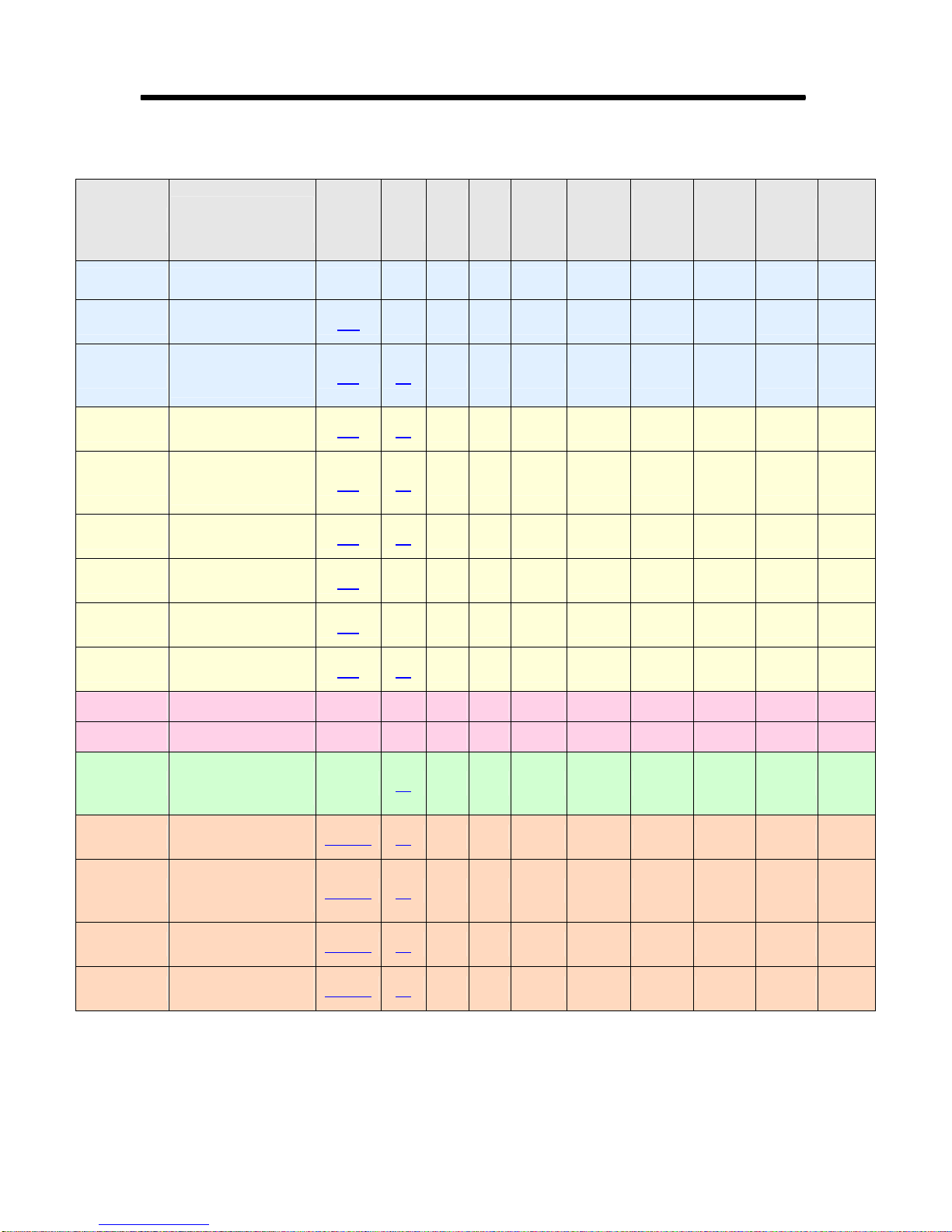
Rastergraf
Table 2-7 Standard Front Panel Board Configurations and Connector Utilization
MDSM
Board Version
TopazPMC/1V VGA 1 VGA 2 PMC Pn4 PMC Pn4
TopazPMC/1L
TopazPMC/1D
TopazPMC/2A
TopazPMC/2B
TopazPMC/2C
TopazPMC/2L
TopazPMC/2N
TopazPMC/2M
VGA: A31-00735-2012
MDR: A31-00735-4012
DVI: A31-00735-1012
MDR: A31-00735-3012
DVI: A31-00735-1012
MDR: A31-00735-3012
DVI: A31-00735-1012
MDR: A31-00735-3012
DVI: A31-00735-1012
MDR: A31-00735-5012
VGA: A31-00735-2012
MDR: A31-00735-8012
VGA: A31-00735-2012
MDR: A31-00735-7012
DVI: A31-00735-1012
MDR: A31-00735-3012
Use
Breakout Cable(s)
or
MDR20/26
Pinout
26C VGA 1 MDR26 MDR26
20A D1 DVI-I DVI-I DVI-I PMC Pn4 PMC Pn4
20A D1 DVI-I DVI-I DVI-I PMC Pn4 PMC Pn4 MDR20 MDR20
20A D2 DVI-I DVI-I PMC Pn4 PMC Pn4
20B D1 DVI-I DVI-I DVI-I PMC Pn4 PMC Pn4 MDR20
26A VGA 1
26B VGA 1
20A D1 DVI-I DVI-I DVI-I PMC Pn4 PMC Pn4 MDR20 MDR20 PMC Pn4
Pinout
DVI
VGA
out
Ch 1
VGA
out
Ch 2
DVI
Out
Ch 1
PMC
Pn4
PMC
Pn4
LVDS
Out
Ch 1
MDR26 MDR26 MDR26
MDR26 MDR26
LVDS
Out
Ch 2
NTSC/
PAL
Video I/O
VGA 1
comp out
MDR20
video out
only
MDR20
video out
only
RGBHV
In
DVI-I
DVI In
TroposPMC/1V VGA 1 PMC Pn4 PMC Pn4
TroposPMC/1D DVI: A31-00735-1012 DVI-I PMC Pn4 PMC Pn4
MDSM
video out
only
MDSM
video out
only
DVI
StratusPMC/1D
StratusPMC/2A
StratusPMC/2B
StratusPMC/2C
StratusPMC/2M
DVI: A31-00735-1012
MDSM: A31-00735-0036
DVI: A31-00735-1012
MDSM: A31-00735-0036
DVI: A31-00735-1012
MDSM: A31-00735-0036
DVI: A31-00735-1012
MDSM: A31-00735-6012
DVI: A31-00735-1012
MDSM: A31-00735-0036
D1 DVI-I DVI-I DVI-I PMC Pn4 PMC Pn4
MDSMA D1 DVI-I DVI-I DVI-I PMC Pn4 PMC Pn4 MDSM MDSM
MDSMA D2 DVI-I DVI-I PMC Pn4 PMC Pn4
MDSMB D1 DVI-I DVI-I DVI-I PMC Pn4 PMC Pn4 MDSM
MDSMA D1 DVI-I DVI-I DVI-I PMC Pn4 PMC Pn4 MDSM MDSM PMC Pn4
2-18 Specifications

Rastergraf
Table 2-8 Standard Rear Panel Board Configurations and I/O Assignments
TopazPMC/1R2
(DVI Out)
TopazPMC/1R/RT
(RG-101 Compatible VGA)
TopazPMC/2R3
(DVI Out / Analog RGB In)
TopazPMC/2R4
(DVI In or Analog RGB In)
TopazPMC/2R8
(Second VGA Out /
Analog RGB In)
TopazPMC/2R9
(Second VGA Out / DVI In)
TopazPMC/2R10
(DVI Out / DVI In)
TopazPMC/2R12
LVDS Out / VGA Out)
Dual
Pinout
table
3.20.4
3.20.10
3.20.5
3.20.5
3.20.6
3.20.8
3.20.7
3.20.9
LVDS
Out
Ch
1 & 2
Pn4 Pin
Group 1
Pn4 Pin
Group 1
Pn4 Pin
Group 1
Pn4 Pin
Group 1
Pn4 Pin
Group 1
Pn4 Pin
Group 1
Pn4 Pin
Group 1
VGA
Out
Ch 1
Pn4 Pin
Group 3
Pn4 Pin
Group 6
Pn4 Pin
Group 3
Pn4 Pin
Group 3
Pn4 Pin
Group 3
Pn4 Pin
Group 3
Pn4 Pin
Group 3
Pn4 Pin
Group 3
Composite/
VGA
Out
Ch 2
Pn4 Pin
Group 2
Pn4 Pin
Group 2
DVI
Out
Ch 1
Pn4 Pin
Group 2
Pn4 Pin
Group 2
Pn4 Pin
Group 2
DVI
Pn4 Pin
Group 2
Pn4 Pin
Groups
4 and 5
Pn4 Pin
Groups
4 and 5
In
S-Video/
NTSC/PAL
or
Analog RGB
In
Pn4 Pin
Group 4
Pn4 Pin
Group 4
Pn4 Pin
Group 4
Composite/
S-Video/
NTSC/PAL
Out
Pn4 Pin
Group 5
Pn4 Pin
Group 5
Pn4 Pin
Group 5
GarnetPMC/RIO9
GarnetPMC/RIO10
Compatibility
TroposPMC/RIO2
DurosPMC
StratusPMC/RIO3
GarnetPMC/RIO6
StratusPMC/RIO4
GarnetPMC/RIO7
StratusPMC/RIO5
GarnetPMC/RIO8
See Section 3.20 for more information about connection to Pn4
Table 2-9 Front Panel Board Model Compatibility
TopazPMC/1V
TopazPMC/1D
TopazPMC/1D
TopazPMC/2A-C, L, N
TopazPMC/2 L, N N/A
TopazPMC/2M 3.20.4
3.20.3
Pn4 Pin
Group 1
Pn4 Pin
Group 1
Pn4 Pin
Group 2
TroposPMC/1V
TroposPMC/1D
StratusPMC/1D
Specifications 2-19

Rastergraf
2.6 Software Support
Rastergraf provides a broad range of software support. The following table
shows the current availability. Please contact Rastergraf Sales for special
requirements.
Table 2-10 Software
Operating System
Software
X Window System
Video Input Extension
BIOS
(supports analog RGBHV,
sync-on-green, and DVI)
SDL
(Graphics Subroutine Library)
WindML
(runs under SDL)
BIST
(runs under SDL)
Linux VxWorks
XFree86
4.3
bttv bttv btwincap bttv
VGA
(x86)
yes yes yes
yes yes
yes yes
XFree86
4.3
VGA n/a
Windows
2000, XP
LynxOS 4
XFree86
4.3
2-20 Specifications

Rastergraf
Chapter 3
Connector Pinouts and Cable
Information
Connector Pinouts and Cable Information 3-1

Rastergraf
3.1 Introduction
A variety of front panel connectors and both standard and breakout cables
are required for the Topaz, Stratus, and Tropos boards and are covered in
the following sections. See Table 3-1 (two pages on) for a guide to the
chapter’s contents. Also, see Section 2.5
related information.
The Topaz/Stratus/Tropos DVI-I breakout cable splits out DVI, primary
VGA, and with the unused DVI dual link pins, secondary VGA. The
Topaz/Stratus MDSM or MDR20 Video I/O breakout cable splits out
video in and out into BNC and/or S-Video connections.
The Garnet and Duros use only PMC Pn4 rear panel connectors. At this
time, there are no cables, breakouts, or PIMs for use with PMC Pn4.
The Topaz, Stratus, and Tropos can also be ordered in rear panel
configurations.
Rastergraf can supply you with the breakout and extension cables that are
described in this chapter. Please contact Rastergraf sales for any assistance
you may need.
for board part numbers and
Cable Sources
Rastergraf uses an outside contractor to build its production cables:
Lynn Products, Inc. http://www.lynnprod.com
3-2 Connector Pinouts and Cable Information

Table 3-1 Front Panel Signal Definitions
Pn4/Schematic Name Function
Rastergraf
LVDSA_TX3P,
LVDSB_TX3P, etc.
LVDS Ch A and Ch B (respectively) signals.
LVDSA_TX3P/ LVDSA _TX3N would make up a
high-speed differential pair.
DVID_TXCP, etc.
DVIB_TXCP, etc.
DVI In signals. DVID_TXCP/DVID_TXCN would
make up a high-speed differential pair.
DVI Out signals. DVIB_TXCP/DVIB_TXCN
would make up a high-speed differential pair.
Note that all lines must be the same length and each
pair must use twisted pair with shield cabling. Each
shield must be separately tied to ground, not all
shields together and then to ground.
VIN3/HS_HSYNC, etc. This is a signal pin shared between the Bt835
NTSC/PAL/SECAM decoder and the high-speed
AD9882 RGBHV decoder.
VIN indicates a Bt835 video input multiplexer
input. Numeral indicates which physical port. VIN3
would be the fourth (0-3) input.
HS_ means high-speed signal. HSYNC is, of
course, horizontal sync input.
GREEN, etc. or
Primary Green, etc.
SO_GREEN, etc. or
Secondary Green, etc.
Part of the Primary VGA output.
Part of the Secondary VGA output.
RED, GREEN, and BLUE must use 75-ohm coax.
Each shield must be separately tied to ground, not
all shields together and then to ground.
HSYNC and VSYNC should each be twisted pair
with a ground. SDC and SDA can be straight or
twisted pairs.
COUT, etc. Part of the component or composite video output
signal set.
Connector Pinouts and Cable Information 3-3

Rastergraf
Table 3-2 Front and Rear Panel Connector Usage
Section
3.2 VGA
3.3 DVI-I D1, D2
3.4 MDR20 MDR20A, B TopazPMC/2A-C, M Board side connector
3.5 MDR26 MDR26A-C TopazPMC/1L, 2L, 2N Board side connector
3.6 MSDM-15 MDSMA, B StratusPMC/2x Board side connector
3.7 S-Video
3.8 VGA A31-00599-1012 TroposPMC/1V VGA to VGA Cable
3.9
3.10 DVI-I, VGA A31-00735-1012 D2 Topaz/ Stratus/Tropos
3.11 DVI, VGA
3.12 VGA A31-00735-2012 Topaz VGA Topaz PMC/1L, 2L, 2N VGA Breakout Cable
3.13 MDR20 A31-00735-3012 MDR20A TopazPMC/2A, B, M Video I/O Breakout Cable
3.14 MDR20 A31-00735-5012 MDR20B TopazPMC/2C DVI In Breakout Cable
3.15 MDR26 A31-00735-8012 MDR26A Topaz PMC/2L
3.16 MDR26 A31-00735-7012 MDR26B Topaz PMC/2N
3.17 MDR26 A31-00735-4012 MDR26C Topaz PMC/1L LVDS Extension Cable
3.18 MSDM-15 A31-00735-0036 MDSMA StratusPMC/2A, 2M Video I/O Breakout Cable
3.19 MSDM-15 A31-00735-6012 MDSMB StratusPMC/2C DVI In Breakout Cable
3.20
Connector
Type
S-Video,
BNC
2 row x 64
PMC
Cable P/N Pinout(s) Board Version(s) Where Used
A31-00709-1003,
VAD44
88741-8700,
A31-00599-5012
D1
Pn1, Pn2,
Pn4
TopazPMC/1V
TroposPMC/1V
TopazPMC/1D
TopazPMC/2x
StratusPMC/1D
StratusPMC/2x
TroposPMC/1D
TopazPMC/2A, B, M
StratusPMC/2A, 2M
TopazPMC/2A, B, M
StratusPMC/2A, 2M
TopazPMC/1D
StratusPMC/1D
StratusPMC/2x
TroposPMC/1D
All
Board side connector
Board side connector
Breakout Cables
S-Video Adapters
Multifunction Breakout
Cable
DVI to VGA Adapters
Video I/O + LVDS Out
Breakout Cable
DVI In + LVDS Out
Breakout Cable
PMC bus to host
rear panel I/O
3-4 Connector Pinouts and Cable Information

3.2 VGA Connector
Analog graphics output is provided on a standard VGA style compressed
15 pin D-Sub and is used with an “Autoscan” type monitor. You must use
the correct initialization, since a VGA monitor depends on the sync
polarities to determine operating frequency. The polarities of the
Vertical/Composite Sync and Horizontal Sync are controlled by the
SM731 graphics controller chip (see Section 5.2
4.7 concerning composite sync on green and RGBHV video out modes.
If you have problems, please contact Rastergraf for assistance.
The R, G, and B video outputs are driven by the SM731 graphics
controller chip which is capable of driving terminated cable (75 ohms) to
standard RS-330/IRE levels. Cable length should be limited to 50 feet
unless you use low loss RG-59.
If you really want to roll you own, the PMC board side VGA connector is
an AMP 788574-1. Be sure to use 75-ohm coax for the R, G, B. You can
use TP or coax on H, and V. A cable that would work is Mogami W32068 (http://www.mars-cam.com/ccd/mogami/digital3.html
Rastergraf
). See the Note in Section
).
Important Note
Because two VGA connectors are a tight fit on the TopazPMC/1V, some
VGA connector moldings are too wide to allow two cables to be plugged
in simultaneously. Rastergraf can supply cables that are known to fit. The
cable part number is A31-00599-1012. See Section 3.8.
Connector Pinouts and Cable Information 3-5

Rastergraf
Table 3-3 Analog (VGA) Video Connector Pinout
VGA
Pin
1 Red 75 ohm Coax with pin 6 Ground
2 Green 75 ohm Coax with pin 7 Ground
3 Blue 75 ohm Coax with pin 8 Ground
4 VOUT * 75 ohm Coax with pin 5 Ground
5 DDC Ground Circuit Ground
6 Red Ground Circuit Ground
7 Green Ground Circuit Ground
8 Blue Ground Circuit Ground
9 Fused +5 Volts, .25A max
10 Sync Ground Circuit Ground
11 Ground Circuit Ground
12 DDCDA
13 HSYNC Twisted Pair with pin 5 Ground
14 VSYNC
Description Ground Type Cable Type
Twisted Pair with pin 10
Ground
Twisted Pair with pin 10
Ground
15 DDCCK Twisted Pair with pin 5 Ground
- Connector Shell Chassis Ground
- Outer Shield (Cable Jacket) Chassis Ground
*Note that Pin 4 is only used only on TopazPMC
Warning:
The Chassis Ground MUST NOT BE CONNECTED to Circuit Ground.
3-6 Connector Pinouts and Cable Information

3.3 DVI-I Connector
Topaz, Stratus, and Tropos boards that support DVI use the industry
standard DVI-I (analog/digital) connector which carries both the DVI
digital and the traditional RGBHV analog graphics signals. See
http://www.ddwg.org/
StratusPMC bring out the second VGA channel on some DVI spare pins
(see next page).
The DVI protocol uses the TMDS encoded data format. Each of the three
differential data pairs encodes nine digital video (TTL) signals. A separate
pair carries the clock. DVI requires all pairs be closely matched in length..
Note that there is only one DVI channel, It is driven by an external DVI
encoder connected the SM731 24-bit FP channel output. The encoder is a
THine THC63DV164 DVI transmitter (http://www.thine.co.jp
best quality, we strongly urge you to obtain commercially manufactured
cables and/or adapters that are available from Rastergraf, Molex, and other
well-known suppliers.
Rastergraf
for more information. The TopazPMC/2 and
). To ensure
Table 3-4 Tropos DVI-I Connector (Pinout D1)
DVI-I Pin Description
1 DVI_TX2L
2 DVI_TX2H
3 DVI_TX2 Shield/Ground
6 DDCCK
7 DDCDA
8 Vertical Sync
9 DVI_TX1L
10 DVI_TX1H
11 DVI_TX1 Shield/Ground
14 Fused +5 Volts, .25A max
15 Ground
17 DVI_TX0L
18 DVI_TX0H
19 DVI_TX0 Shield/Ground
22 DVI_TXC Shield/Ground
23 DVI_TXCH
24 DVI_TXCL
4, 5, 12, 13, 16, 20, 21 n/c
C1 Red
C2 Green
C3 Blue
C4 Horizontal Sync
C5 Analog Ground
Connector Pinouts and Cable Information 3-7

Rastergraf
TopazPMC/2 and StratusPMC Modified DVI-I Connector
The TopazPMC/2 and StratusPMC use the standard DVI-I connector on
the front panel. However, in order to get access to the second VGA port,
they use the DVI pins reserved for super-high-resolution dual-link DVI.
Dual link will never be supported on TopazPMC/2 and StratusPMC.
Note that there is only one DVI channel, It is driven by an external DVI
encoder connected the SM731 24-bit FP channel output.
A breakout cable (A31-00749-1012) is available. See Section 3.10
more information.
The table below shows the usage of the DVI-I pins for the TopazPMC/2
and StratusPMC. Non-standard usages are shown in
bold italic.
Table 3-5 TopazPMC/2 and StratusPMC DVI-I Connector (Pinout D2)
DVI-I Pin Description
1 DVI_TX2L
2 DVI_TX2H
3 DVI_TX2 Shield/Ground
4 Secondary VGA Red
5 Secondary VGA Vertical Sync
6 DVI/ Primary VGA DDCCK
7 DVI/ Primary VGA DDCDA
8 Primary VGA Vertical Sync
9 DVI_TX1L
10 DVI_TX1H
11 DVI_TX1 Shield/Ground
12 Secondary VGA Green
13 Secondary VGA DDCCK
14 Fused +5 Volts, .25A max
15 Ground
16 Secondary VGA DDCDA
17 DVI_TX0L
18 DVI_TX0H
19 DVI_TX0 Shield/Ground
20 Secondary VGA Blue
21 Secondary VGA Horizontal Sync
22 DVI_TXC Shield/Ground
23 DVI_TXCH
24 DVI_TXCL
C1 Primary VGA Red
C2 Primary VGA Green
C3 Primary VGA Blue
C4 Primary VGA Horizontal Sync
C5 Analog Ground
for
3-8 Connector Pinouts and Cable Information

3.4 MDR20 Connector
The TopazPMC/2 uses a 20-pin 3M# 10220-1210VE female MDR
connector for Video I/O (VI/O). Rastergraf can supply a breakout cable
that provides a set of BNCs and S-Video connectors. No BNC to S-Video
adapters are required.
Table 3-6 Video I/O (VI/O) Front Panel Connector (Pinouts 20A & 20B)
MDR Pin MDR20 MDR20
Number Pinout 20A Pinout 20B
1, 11 Ground Ground
2 YOUT DVI_IN_ TXCLKN
12 VOUT DVI_IN_ TXCLKP
3 YIN_VIN0/HS_RED DVI_IN_ TX1P
13 VIN1/HS_GREEN DVI_IN_ TX1N
4, 14 Ground Ground
5 COUT DVI_IN_TX2N
15 CIN/HS_VSYNC DVI_IN_TX2P
6 VIN2/HS_BLUE DVI_IN_ TX0P
16 VIN3HS_HSYNC DVI_IN_ TX0N
7 Ground Ground
17
8-10, 18-20 n/c n/c
Rastergraf
F5V F5V
3.4.1 MDR20 Pinout 20A – NTSC/PAL or RGBHV In, NTSC/PAL Out
The MDR20 Pinout 20A supports dual use pins. The NTSC/PAL and
high-speed RGB input signals are connected together on the board. They
are shown in the table to illustrate the different capabilities of the board.
NTSC/PAL Input
VIN0-VIN3 are composite NTSC/PAL Inputs and CIN is an input
dedicated to Chrominance. VIN 0 can be used with the CIN for S-Video
input applications. Each input is connected to the digitizing chips by a .1
uF input capacitor and presents a (DC) 75-ohm impedance to the driving
source. No low pass filtering is done on the signals. The Bt835 multiplexer
is
not break-before-make, so inputs will be momentarily connected
together when switching from one input to another. YOUT (luminance or
brightness), VOUT, and COUT (chrominance or color) are the outputs of
the SM731 VGA to NTSC/PAL encoder.
Connector Pinouts and Cable Information 3-9

Rastergraf
Loopback Mode
Note that as a test feature, a control bit can make the VOUT loopback to
VIN1. The only time the loopback should be enabled is when VIN1 is not
otherwise connected.
RGBHV Input
The MDR20 connector can be used to connect to the high-speed (HS)
digitizer, which acquires RGBHV or RGB + SOG, up to 1280 x 1024 at
120 MHz. The table above shows the
MDR20 Pinout 20A pin definitions
share pins between the NTSC/PAL digitizer and the high-speed digitizer.
The connections are wired in parallel except for that the 75-ohm
terminations on VIN3 and CIN are removed in HS mode.
3.4.2 MDR20 Pinout 20B – DVI Input
The MDR20 connector can also be used to connect to the DVI inputs of
the high-speed AD9882 digitizer at up to 1024 x 768. The table above
shows the
definitely a second choice to using the DVI-I connector’s (usually) DVI
output function for digitizing. However, if you still need DVI out, then
MDR20 is the best way to provide DVI In.
MDR20 Pinout 20B pin definitions. Using this mode is
3-10 Connector Pinouts and Cable Information

3.5 MDR26 Connector
The TopazPMC/1L uses a 26-pin 3M #10226-1210VE female MDR26
connector to provide single high resolution (1600x1200) or dual medium
resolution (1024x768) LVDS output(s) on the PMC front panel. The
TopazPMC/2L and /2N can provide a single medium resolution
(1024x768) LVDS output plus a variety of NTSC/PAL, high-speed RGB,
or DVI input functions.
Table 3-7 Video I/O (VI/O) Front Panel Connector (Pinouts 26A-26C)
MDR26 Pin MDR26 MDR26 MDR26
Number
1, 14 Ground Ground Ground
2 YOUT DVI_IN_ TXCLKN FLVDSB_TX3P
15 VOUT DVI_IN_ TXCLKP FLVDSB_TX3N
3 YIN_VIN0/HS_RED DVI_IN_ TX1P FLVDSB_TXCP
16 VIN1/HS_GREEN DVI_IN_ TX1N FLVDSB_TXCN
4 Ground Ground FLVDSB_TX2P
17 Ground Ground FLVDSB_TX2N
5 COUT DVI_IN_TX2N FLVDSB_TX1P
18 CIN /HS_VSYNC DVI_IN_TX2P FLVDSB_TX1N
6 VIN2/HS_BLUE DVI_IN_ TX0P FLVDSB_TX0P
19 VIN3/HS_HSYNC DVI_IN_ TX0N FLVDSB_TX0N
7 Ground Ground Ground
20 F5V F5V F5V
8 FLVDSA_TX3P FLVDSA_TX3P FLVDSA_TX3P
21 FLVDSA_TX3N FLVDSA_TX3N FLVDSA_TX3N
9 FLVDSA_TXCP FLVDSA_TXCP FLVDSA_TXCP
22 FLVDSA_TXCN FLVDSA_TXCN FLVDSA_TXCN
10 FLVDSA_TX2P FLVDSA_TX2P FLVDSA_TX2P
23 FLVDSA_TX2N FLVDSA_TX2N FLVDSA_TX2N
11 FLVDSA_TX1P FLVDSA_TX1P FLVDSA_TX1P
24 FLVDSA_TX1N FLVDSA_TX1N FLVDSA_TX1N
12 FLVDSA_TX0P FLVDSA_TX0P FLVDSA_TX0P
25 FLVDSA_TX0N FLVDSA_TX0N FLVDSA_TX0N
13, 26 Ground Ground Ground
Pinout 26A Pinout 26B Pinout 26C
Rastergraf
3.5.1 MDR26 Pinout 26A – Video In, Video Out, Ch 1 LVDS Out
The MDR26 Pinout 26A supports dual use pins. The NTSC/PAL and
high-speed RGB video input signals are connected together on the board.
They are shown in the table to illustrate the different capabilities of the
board.
NTSC/PAL Input
VIN0-VIN3 are composite NTSC/PAL Inputs and CIN is an input
dedicated to Chrominance. VIN 0 can be used with the CIN for S-Video
Connector Pinouts and Cable Information 3-11

Rastergraf
input applications. Each input is connected to the digitizing chips by a .1
uF input capacitor and presents a (DC) 75-ohm impedance to the driving
source. No low pass filtering is done on the signals. The Bt835 multiplexer
is
not break-before-make, so inputs will be momentarily connected
together when switching from one input to another. YOUT (luminance or
brightness), VOUT, and COUT (chrominance or color) are the outputs of
the SM731 VGA to NTSC/PAL encoder.
Loopback Mode
Note that as a test feature, a control bit can make the VOUT loopback to
VIN1. The only time the loopback should be enabled is when VIN1 is not
otherwise connected.
RGBHV Input
The MDR26 connector can be used to connect to the high-speed (HS)
digitizer, which acquires RGBHV or RGB + SOG, up to 1280 x 1024 at
120 MHz. The table above shows the
MDR26 Pinout 26A pin definitions
share pins between the NTSC/PAL digitizer and the high-speed digitizer.
The connections are wired in parallel except for that the 75-ohm
terminations on VIN3 and CIN are removed in HS mode.
3.5.2 MDR26 Pinout 26B – DVI Input, Ch 1 LVDS Out
The table above shows the MDR26 Pinout 26B pin definitions which
enable the DVI inputs of the high-speed AD9882 digitizer at up to 1024 x
768. Using this mode is definitely a second choice to using the DVI-I
connector’s (usually) DVI output function for digitizing.
3.5.3 MDR26 Pinout 26C – Ch 1 and CH 2 LVDS Out
The table above shows the MDR26 Pinout 26C pin definitions which
enable the both LVDS ports to be connected. This can support dual 1024 x
768 or a single dual-link 1600x1200 display. For convenience of cabling,
the pinout follows the CameraLink frame grabber side basic configuration.
Not that there is no actual CameraLink support on any board.
3-12 Connector Pinouts and Cable Information

Rastergraf
3.6 MDSM Connector
The Stratus uses a 15-pin ITT Cannon MDSM (MDSM-15PE-Z10)
connector for the Video I/O (VI/O) front panel connector. Rastergraf can
supply a breakout cable that provides a set of 8 BNC connectors.
A BNC (YOUT/COUT) to S-Video DIN can be used to drive S-Video
compatible devices. (http://www.a2zcables.com/
The Cannon cable connector part number is MDSM-15SC-Z11-VS1.
Cannon also has a 3 foot pigtail cable (CA111972-11) which has the
MDSM on one end and uses twisted pair wires. Coax is recommended for
video, so this cable will not give you the best results.
Table 3-8 Video I/O (VI/O) Front Panel Connector (Pinouts MDSMA & MDSMB)
MDSM15 MDSM MDSM15
Pin Number MDSMA MDSMB
1 YOUT DVI_IN_ TXCLKN
2 VOUT DVI_IN_ TXCLKP
3 COUT DVI_IN_TX2N
4 CIN/HS_VSYNC DVI_IN_TX2P
5 YIN_VIN0/HS_RED DVI_IN_ TX1P
6 VIN1/HS_GREEN DVI_IN_ TX1N
7 VIN2/HS_BLUE DVI_IN_ TX0P
8 VIN3HS_HSYNC DVI_IN_ TX0N
9 Ground* Ground*
10-14 Ground Ground
, part number VY6-1).
* Factory option allows this pin to be wired to fused 5V (F5V)
3.6.1 Pinout MDSMA – NTSC/PAL or RGBHV In, NTSC/PAL Out
The Pinout MDSMA supports dual use pins. The NTSC/PAL and high-
speed RGB input signals are connected together on the board. They are
shown in the table to illustrate the different capabilities of the board.
NTSC/PAL Input
VIN0-VIN3 are composite NTSC/PAL Inputs and CIN is an input
dedicated to Chrominance. VIN 0 can be used with the CIN for S-Video
input applications. Each input is connected to the digitizing chips by a .1
uF input capacitor and presents a (DC) 75-ohm impedance to the driving
source. No low pass filtering is done on the signals. The Bt835 multiplexer
is
not break-before-make, so inputs will be momentarily connected
together when switching from one input to another. YOUT (luminance or
Connector Pinouts and Cable Information 3-13

Rastergraf
brightness), VOUT, and COUT (chrominance or color) are the outputs of
the SM731 VGA to NTSC/PAL encoder.
Loopback Mode
Note that as a test feature, a control bit can make the VOUT loopback to
VIN1. The only time the loopback should be enabled is when VIN1 is not
otherwise connected.
RGBHV Input
The MDSM15 connector can be used to connect to the high-speed (HS)
digitizer, which acquires RGBHV or RGB + SOG, up to 1280 x 1024 at
120 MHz. The table above shows the
share pins between the NTSC/PAL digitizer and the high-speed digitizer.
The connections are wired in parallel except for that the 75-ohm
terminations on VIN3 and CIN are removed in HS mode.
3.6.2 Pinout MDSMB – DVI Input
The MDSM15 connector can also be used to connect to the DVI inputs of
the high-speed AD9882 digitizer at up to 1024 x 768. The table above
shows the
second choice to using the DVI-I connector’s (usually) DVI output
function for digitizing.
Pinout MDSMB pin definitions. Using this mode is definitely a
Pinout MDSMA pin definitions
.
3-14 Connector Pinouts and Cable Information

3.7 S-Video Connector
We use the S-Video connector for high quality video-in because it is the
most common type and is also widely used on PCs and personal video
equipment. This makes it easy to get cables and connectors.
Figure 3-1 S-Video Connector
Rastergraf
Pin Description
1 Ground (Y)
Male connector
solder side view
2 Ground (C)
Y (Luminance = intensity + Sync.)
3
4 C (Chrominance = color)
or Composite Video In
Connector Pinouts and Cable Information 3-15

Rastergraf
3.8 VGA to VGA Cable
Because two VGA connectors are a tight fit on a PMC board, some VGA
connector moldings are too wide to allow two cables to be plugged in
simultaneously. Rastergraf can supply cables that are known to fit.
Table 3-9 VGA to VGA Cable (A31-00599-1012)
VGA (P1) VGA (C2) Wire Description
Pin Pin Type Function Name
2 2 75 coax #G VGA Green
7 7 75 coax #G VGA Green Ground
3 3 75 coax #B VGA Blue
8 8 75 coax #B VGA Blue Ground
1 1 75 coax #R VGA Red
6 6 75 coax #R VGA Red Ground
14 14 TP+S #V VGA VS
10 10 TP+S #V VGA Sync Ground
13 13 TP+S #H VGA HS
11 11 TP+S #H VGA Ground
12 12 straight DVI/VGA SDA
15 15 straight DVI/VGA SCL
5 5 straight DVI/VGA DDC Ground
9 9 straight
F5V
Figure 3-2 VGA to VGA Extension Cable (A31-00599-1012)
P1 C1
3-16 Connector Pinouts and Cable Information
12 in

3.9 S-Video Adapter Cables
The TopazPMC/2 VIO breakout cable has two S-Video connectors, one
for input and one for output (see Section 3.8
S-Video cable can be used as a standard composite input. The
A31-00709-1003 S-Video to BNC adapter cable is supplied for that
purpose.
Table 3-10 TopazPMC S-Video to BNC adapter cable (A31-00709-1003)
Rastergraf
). One pin on the input
BNC
(P2)
Pin Pin Type Function Name
2 3 75 coax #BLK Video In Composite Video In
1 1 75 coax # BLK Video In Ground
S-Video Wire
Description
Figure 3-3 S-Video to BNC Adapter (A31-00709-1003)
Connector Pinouts and Cable Information 3-17

Rastergraf
The StratusPMC/2 has eight BNCs, of which 2 pairs, VOUT+COUT and
YIN_VIN0+CIN, can be used for S-Video. The VAD44 cable
(http://store.a2zcable.com/vad44.html
) BNC (YOUT/COUT) to S-Video
adapter can be used to provide S-Video Input and Output connections.
Table 3-11 StratusPMC BNC to S-Video Adapter Cable (VAD44)
BNC BNC S-Video Wire Description
Pin Connector Pin Type Function Name
Center Y 3 75 coax #BLK Video Out Y
Shell Y 1 75 coax # BLK Video Out Ground
Center C 4 75 coax # BLK Video Out C
Shell C 2 75 coax # BLK Video Out Ground
Figure 3-4 BNC to S-Video Adapter Cable (VAD44)
3-18 Connector Pinouts and Cable Information

3.10 DVI-I Multifunction Breakout Cable
The DVI-I Multifunction cable addresses the common PMC problem of
insufficient front panel space to allow access to all of its functions. Using
spare pins on the DVI-I connector, it provides extra signal sets, including
DVI and Primary and Secondary VGA.
Note that there is only one DVI channel, It is driven by an external DVI
encoder connected the SM731 24-bit FP channel output.
The connectors are shown in the same order as is in the diagram, C1 – C3.
Note that P1 is documented in Section 3.3
Figure 3-5 DVI-I Multifunction Breakout Cable (A31-00735-1012)
.
Rastergraf
P1
C1
C2
C3
Connector Pinouts and Cable Information 3-19

Rastergraf
3.10.1 C1 – Primary VGA
Table 3-12 C1 - Primary VGA Connector
DVI-I VGA Wire Description
Pin Pin Type Function Name
26 (C2) 2 75 coax #G VGA Green
30 (C5) 7 75 coax #G VGA Green Ground
27 (C3) 3 75 coax #B VGA Blue
29 (C5) 8 75 coax #B VGA Blue Ground
25 (C1) 1 75 coax #R VGA Red
29 (C5) 6 75 coax #R VGA Red Ground
8 14 TP+S #V VGA VS
22 10 TP+S #V VGA Sync Ground
28 (C4) 13 TP+S #H VGA HS
11 11 TP+S #H VGA Ground
7 12 straight DVI/VGA SDA
6 15 straight DVI/VGA SCL
11 5 straight DVI/VGA DDC Ground
14 9 straight F5V
3.10.2 C2 – Secondary VGA
Table 3-13 C2 - Secondary VGA Connector
DVI-I VGA Wire Description
Pin Pin Type Function Name
12 2 75 coax #G VGA Green
15 7 75 coax #G VGA Green Ground
20 3 75 coax #B VGA Blue
15 8 75 coax #B VGA Blue Ground
4 1 75 coax #R VGA Red
15 6 75 coax #R VGA Red Ground
5 14 TP+S #V VGA VS
19 10 TP+S #V VGA Sync Ground
21 13 TP+S #H VGA HS
3 11 TP+S #H VGA Ground
16 12 straight Sec VGA SDA
13 15 straight Sec VGA SCL
3 5 straight Sec VGA DDC Ground
14 9 straight F5V
3-20 Connector Pinouts and Cable Information

3.10.3 C3 – DVI
Rastergraf
Table 3-14 C3 - DVI-D Connector
DVI-I DVI-D Wire
Pin Pin Type
15 15 straight DVI/VGA Sync/DDC Ground
7 7 straight DVI/VGA SDA
6 6 straight DVI/VGA SCL
14 14 straight F5V
23 23 TP+S #C DVI
24 24 TP+S #C DVI
22 22 TP+S #C DVI
18 18 TP+S #0 DVI
17 17 TP+S #0 DVI
19 19 TP+S #0 DVI
10 10 TP+S #1 DVI
9 9 TP+S #1 DVI
11 11 TP+S #1 DVI
2 2 TP+S #2 DVI
1 1 TP+S #2 DVI
3 3 TP+S #2 DVI
Function Name
Description
DVIC_TXCLKP
DVIC_TXCLKN
Pair DCK Ground
DVIC_TX0P
DVIC_TX0N
Pair D0 Ground
DVIC_TX1P
DVIC_TX1N
Pair D1 Ground
DVIC_TX2P
DVIC_TX2N
Pair D2 Ground
Connector Pinouts and Cable Information 3-21

Rastergraf
3.11 DVI-I to VGA Adapters
On the DVI-optioned boards, a DVI-I connector is used. If you need
ONLY the VGA output, a cable-based or modular adapter can be used to
supply analog video to a standard VGA
diagrams on this and the following page.
Table 3-15 DVI-I to VGA Adapter
DVI-I VGA Connector Wire Description
Pin Pin Type Type Function Name
2 2 female VGA 75 coax #G VGA Green
7 7 female VGA 75 coax #G VGA Green Ground
3 3 female VGA 75 coax #B VGA Blue
8 8 female VGA 75 coax #B VGA Blue Ground
1 1 female VGA 75 coax #R VGA Red
6 6 female VGA 75 coax #R VGA Red Ground
14 14 female VGA TP+S #V VGA VS
10 10 female VGA TP+S #V VGA Sync Ground
13 13 female VGA TP+S #H VGA HS
11 11 female VGA TP+S #H VGA Ground
12 12 female VGA straight DVI/VGA SDA
15 15 female VGA straight DVI/VGA SCL
5 5 female VGA straight DVI/VGA DDC Ground
9 9 female VGA straight F5V
computer side connector. See the
Figure 3-6 Molex 88741-8700 DVI-I to VGA Adapter
3-22 Connector Pinouts and Cable Information

Figure 3-7 DVI to VGA Adapter Cable (A31-00599-5012)
Rastergraf
305 mm +/- 12 mm
Connector Pinouts and Cable Information 3-23

Rastergraf
3.12 TopazPMC VGA Breakout Cable
The TopazPMC VGA breakout cable uses a spare pin on the VGA
connector to bring out composite video out. It is used on the
TopazPMC/1L version, which has VGA out and dual LVDS out. Note that
P1 is documented in Section 3.3
Figure 3-8 TopazPMC VGA Breakput Cable (A31-00735-2012)
.
P1
Table 3-16 TopazPMC VGA Breakout Connector
P1 C1 C2 Connector Wire Description
Pin Pin Pin Type Type Function Name
2 2 female VGA 75 coax #G VGA Green
7 7 female VGA 75 coax #G VGA Green Ground
3 3 female VGA 75 coax #B VGA Blue
8 8 female VGA 75 coax #B VGA Blue Ground
1 1 female VGA 75 coax #R VGA Red
6 6 female VGA 75 coax #R VGA Red Ground
4 Center female BNC 75 coax #V Comp Out Comp Out
5 Shell female BNC 75 coax #V Comp Out Ground
14 14 female VGA TP+S #V VGA VS
10 10 female VGA TP+S #V VGA Sync Ground
13 13 female VGA TP+S #H VGA HS
11 11 female VGA TP+S #H VGA Ground
12 12 female VGA straight DVI/VGA SDA
15 15 female VGA straight DVI/VGA SCL
5 5 female VGA straight DVI/VGA DDC Ground
9 9 female VGA straight F5V
C1
C2
3-24 Connector Pinouts and Cable Information

Rastergraf
3.13 TopazPMC Video I/O Breakout Cable
The TopazPMC Video I/O Breakout Cable uses the MDR20 connector to
bring in NTSC/PAL/S-Video and high speed RGBHV video inputs and
provide composite and S-Video out. It is used on the TopazPMC/2A, B,
C, and M versions which have the MDR20 connector documented in
Section 3.4
Table 3-17 TopazPMC Video I/O Breakout Cable
MDR20 Connector Connector Connector Wire Description
Pin Number Pin Type Type Function Name
13 C6 center female BNC 75 coax #GRN Video In VIN1/HS_GREEN
11 C6 shell female BNC 75 coax # GRN Video In Ground
6 C7 center female BNC 75 coax #BLU Video In VIN2/HS_BLUE
4 C7 shell female BNC 75 coax # BLU Video In Ground
16 C8 center female BNC 75 coax #VIO Video In VIN3/HS_HSYNC
14 C8 shell female BNC 75 coax # VIO Video In Ground
12 C2 center female BNC 75 coax #BRN Video Out VOUT
11 C2 shell female BNC 75 coax # BRN Video Out Ground
3 C54 3 female S-Video In 75 coax #YEL Video In YIN_VIN0/HS_RED
1 C54 1 female S-Video In 75 coax # YEL Video In Ground
15 C54 4 female S-Video In 75 coax #ORG Video In CIN/HS_VSYNC
14 C54 2 female S-Video In 75 coax # ORG Video In Ground
2 C13 3 female S-Video Out 75 coax #BLK Video Out YOUT
1 C13 1 female S-Video Out 75 coax # BLK Video Out Ground
5 C13 4 female S-Video Out 75 coax #RED Video Out COUT
4 C13 2 female S-Video Out 75 coax # RED Video Out Ground
. See Section 3.9 for the S-Video to BNC Adapter.
Connector Pinouts and Cable Information 3-25
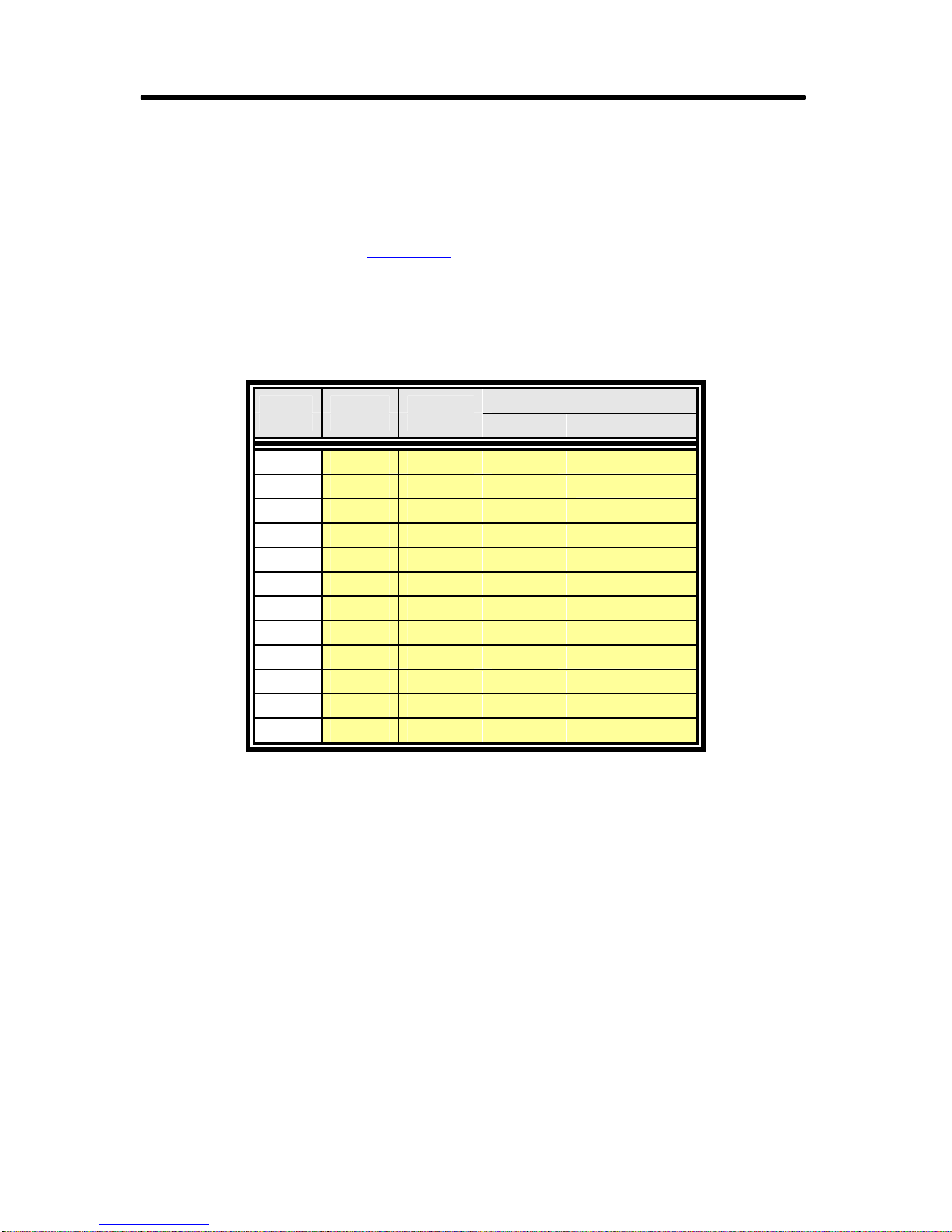
Rastergraf
3.14 TopazPMC DVI In Adapter Cable
The TopazPMC DVI In MDR20 to Female DVI-D Adapter Cable uses the
MDR20 connector to bring in high speed DVI In. It is used on the
TopazPMC/2A, B, C, and M versions which have the MDR20 connector
documented in Section 3.4
Table 3-18 TopazPMC DVI In Adapter Cable
.
MDR20 DVI-D Wire
Pin Pin Type
12 23 TP+S #C DVI
2 24 TP+S #C DVI
1 22 TP+S #C DVI
6 18 TP+S #0 DVI
16 17 TP+S #0 DVI
7 19 TP+S #0 DVI
3 10 TP+S #1 DVI
13 9 TP+S #1 DVI
14 11 TP+S #1 DVI
15 2 TP+S #2 DVI
5 1 TP+S #2 DVI
4 3 TP+S #2 DVI
Description
Function Name
DVID_TXCLKP
DVID_TXCLKN
Pair DCK Ground
DVID_TX0P
DVID_TX0N
Pair D0 Ground
DVID_TX1P
DVID_TX1N
Pair D1 Ground
DVID_TX2P
DVID_TX2N
Pair D2 Ground
3-26 Connector Pinouts and Cable Information

Rastergraf
3.15 TopazPMC Video I/O + LVDS Breakout Cable
The TopazPMC Video I/O + LVDS Breakout Cable uses the MDR26
connector to bring in NTSC/PAL/S-Video and high speed RGBHV video
inputs and provide composite and S-Video out and single-link LVDS out.
It is used on the TopazPMC/2L and N versions which have the MDR26
connector documented in Section 3.5
BNC Adapter.
Table 3-19 TopazPMC Video I/O + LVDS Breakout Cable
MDR20 Connector Connector Connector Wire Description
Pin Number Pin Type Type Function Name
16 C6 center female BNC 75 coax #GRN Video In VIN1/HS_GREEN
14 C6 shell female BNC 75 coax # GRN Video In Ground
6 C7 center female BNC 75 coax #BLU Video In VIN2/HS_BLUE
4 C7 shell female BNC 75 coax # BLU Video In Ground
19 C8 center female BNC 75 coax #VIO Video In VIN3HS_HSYNC
17 C8 shell female BNC 75 coax # VIO Video In Ground
15 C2 center female BNC 75 coax #BRN Video Out VOUT
14 C2 shell female BNC 75 coax # BRN Video Out Ground
3 C54 3 female S-Video In 75 coax #YEL Video In YIN_VIN0/HS_RED
1 C54 1 female S-Video In 75 coax # YEL Video In Ground
18 C54 4 female S-Video In 75 coax #ORG Video In CIN/HS_VSYNC
17 C54 2 female S-Video In 75 coax # ORG Video In Ground
2 C13 3 female S-Video Out 75 coax #BLK Video Out YOUT
1 C13 1 female S-Video Out 75 coax # BLK Video Out Ground
5 C13 4 female S-Video Out 75 coax #RED Video Out COUT
4 C13 2 female S-Video Out 75 coax # RED Video Out Ground
8 C9 8 Male MDR26 TP+S #3 LVDS Out FLVDSA_TX3P
21 C9 21 Male MDR26 TP+S #3 LVDS Out FLVDSA_TX3N
1 C9 1 Male MDR26 TP+S #3 LVDS Out Ground
9 C9 9 Male MDR26 TP+S #C LVDS Out FLVDSA_TXCP
22 C9 22 Male MDR26 TP+S #C LVDS Out FLVDSA_TXCN
14 C9 14 Male MDR26 TP+S #C LVDS Out Ground
10 C9 10 Male MDR26 TP+S #2 LVDS Out FLVDSA_TX2P
23 C9 23 Male MDR26 TP+S #2 LVDS Out FLVDSA_TX2N
13 C9 13 Male MDR26 TP+S #2 LVDS Out Ground
11 C9 11 Male MDR26 TP+S #1 LVDS Out FLVDSA_TX1P
24 C9 24 Male MDR26 TP+S #1 LVDS Out FLVDSA_TX1N
26 C9 26 Male MDR26 TP+S #1 LVDS Out Ground
12 C9 12 Male MDR26 TP+S #0 LVDS Out FLVDSA_TX0P
25 C9 25 Male MDR26 TP+S #0 LVDS Out FLVDSA_TX0N
13 C9 13 Male MDR26 TP+S #0 LVDS Out Ground
. See Section 3.9 for the S-Video to
Connector Pinouts and Cable Information 3-27

Rastergraf
3.16 TopazPMC DVI In + LVDS Breakout Cable
The TopazPMC DVI In + LVDS Breakout Cable uses the MDR26
connector to bring in DVI and single-link LVDS out. It is used on the
TopazPMC/2L and N versions which have the MDR26 connector
documented in Section 3.5
Table 3-20 TopazPMC DVI In + LVDS Breakout Cable
MDR20 Connector Connector Connector Wire Description
Pin Number Pin Type Type Function Name
.
15
2
1
6
19
7
3
16
14
5
18
4 C1
8 C2 8 Male MDR26 TP+S #3 LVDS Out FLVDSA_TX3P
21 C2 21 Male MDR26 TP+S #3 LVDS Out FLVDSA_TX3N
1 C2 1 Male MDR26 TP+S #3 LVDS Out Pair L3 Ground
9 C2 9 Male MDR26 TP+S #C LVDS Out FLVDSA_TXCP
22 C2 22 Male MDR26 TP+S #C LVDS Out FLVDSA_TXCN
14 C2 14 Male MDR26 TP+S #C LVDS Out Pair LCK Ground
10 C2 10 Male MDR26 TP+S #2 LVDS Out FLVDSA_TX2P
23 C2 23 Male MDR26 TP+S #2 LVDS Out FLVDSA_TX2N
13 C2 13 Male MDR26 TP+S #2 LVDS Out Pair L2 Ground
11 C2 11 Male MDR26 TP+S #1 LVDS Out FLVDSA_TX1P
24 C2 24 Male MDR26 TP+S #1 LVDS Out FLVDSA_TX1N
26 C2 26 Male MDR26 TP+S #1 LVDS Out Pair L1 Ground
12 C2 12 Male MDR26 TP+S #0 LVDS Out FLVDSA_TX0P
25 C2 25 Male MDR26 TP+S #0 LVDS Out FLVDSA_TX0N
13 C2 13 Male MDR26 TP+S #0 LVDS Out Pair L0 Ground
C1
C1
C1
C1
C1
C1
C1
C1
C1
C1
C1
23
24
22
18
17
19
10
9
11
2
1
3
female DVI-D
female DVI-D
female DVI-D
female DVI-D
female DVI-D
female DVI-D
female DVI-D
female DVI-D
female DVI-D
female DVI-D
female DVI-D
female DVI-D
TP+S #C DVI DVID_TXCLKP
TP+S #C DVI DVID_TXCLKN
TP+S #C DVI Pair DCK Ground
TP+S #0 DVI DVID_TX0P
TP+S #0 DVI DVID_TX0N
TP+S #0 DVI Pair D0 Ground
TP+S #1 DVI DVID_TX1P
TP+S #1 DVI DVID_TX1N
TP+S #1 DVI Pair D1 Ground
TP+S #2 DVI DVID_TX2P
TP+S #2 DVI DVID_TX2N
TP+S #2 DVI Pair D2 Ground
3-28 Connector Pinouts and Cable Information

3.17 TopazPMC LVDS Extension Cable
The TopazPMC LVDS Extension Cable has two male MDR26 connectors.
It supports dual-link high resolution or two single-link medium resolution
LVDS panels. It is used on the TopazPMC/1L version which has the
MDR26 connector documented in Section 3.5
The cable is the same as the 3M #14B26-SZLB-300-0LC (3 meter with
thumbscrews) cable. Note that the connections are not the same at each
connector, but rather are cross-wired according to the chart on the next
page. By convention, the TopazPMC/1L follows the “Frame Grabber”
end, although, of course, it is a display device, not a frame grabber.
Figure 3-9 TopazPMC LVDS Extension Cable (A31-00735-4012)
.
Rastergraf
3m
Connector Pinouts and Cable Information 3-29
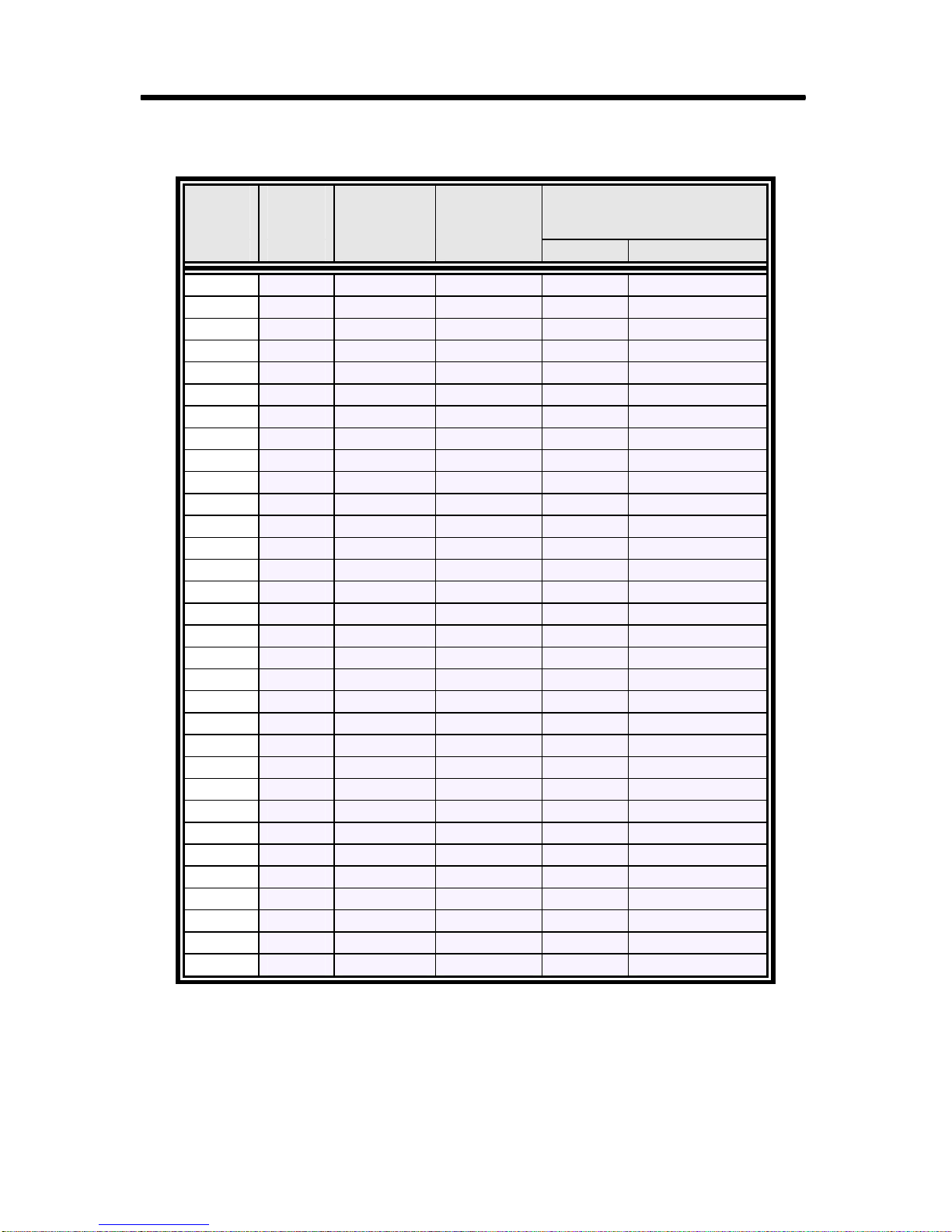
Rastergraf
Table 3-21 TopazPMC LVDS Extension Cable (A31-00735-4012)
Topaz
side
MDR26
Pin Pin Type Type Function Name
2 25 Male MDR26 TP+S #B3 LVDS Out FLVDSB_TX3P
15 12 Male MDR26 TP+S #B3 LVDS Out FLVDSB_TX3N
13 14 Male MDR26 TP+S #B3 LVDS Out Pair BL3 Ground
3 24 Male MDR26 TP+S #BC LVDS Out FLVDSB_TXCP
16 11 Male MDR26 TP+S #BC LVDS Out FLVDSB_TXCN
26 1 Male MDR26 TP+S #BC LVDS Out Pair BLCK Ground
4 23 Male MDR26 TP+S #B2 LVDS Out FLVDSB_TX2P
17 10 Male MDR26 TP+S #B2 LVDS Out FLVDSB_TX2N
13 14 Male MDR26 TP+S #B2 LVDS Out Pair BL2 Ground
5 22 Male MDR26 TP+S #B1 LVDS Out FLVDSB_TX1P
18 9 Male MDR26 TP+S #B1 LVDS Out FLVDSB_TX1N
26 1 Male MDR26 TP+S #B1 LVDS Out Pair BL1 Ground
6 21 Male MDR26 TP+S #B0 LVDS Out FLVDSB_TX0P
19 8 Male MDR26 TP+S #B0 LVDS Out FLVDSB_TX0N
13 14 Male MDR26 TP+S #B0 LVDS Out Pair BL0 Ground
7 20 Male MDR26 TP+S #C0 Term 100 ohm term P
20 7 Male MDR26 TP+S #C0 Term 100 ohm term N
8 19 Male MDR26 TP+S #A3 LVDS Out FLVDSA_TX3P
21 6 Male MDR26 TP+S #A3 LVDS Out FLVDSA_TX3N
14 13 Male MDR26 TP+S #A3 LVDS Out Pair AL3 Ground
9 18 Male MDR26 TP+S #AC LVDS Out FLVDSA_TXCP
22 5 Male MDR26 TP+S #AC LVDS Out FLVDSA_TXCN
1 26 Male MDR26 TP+S #AC LVDS Out Pair ALCK Ground
10 17 Male MDR26 TP+S #A2 LVDS Out FLVDSA_TX2P
23 4 Male MDR26 TP+S #A2 LVDS Out FLVDSA_TX2N
14 13 Male MDR26 TP+S #A2 LVDS Out Pair AL2 Ground
11 16 Male MDR26 TP+S #A1 LVDS Out FLVDSA_TX1P
24 3 Male MDR26 TP+S #A1 LVDS Out FLVDSA_TX1N
1 26 Male MDR26 TP+S #A1 LVDS Out Pair AL1 Ground
12 15 Male MDR26 TP+S #A0 LVDS Out FLVDSA_TX0P
25 2 Male MDR26 TP+S #A0 LVDS Out FLVDSA_TX0N
14 13 Male MDR26 TP+S #A0 LVDS Out Pair AL0 Ground
Far
end
MDR26
Connector Wire Description
3-30 Connector Pinouts and Cable Information

3.18 StratusPMC Video I/O Breakout Cable
The StratusPMC Video I/O Breakout Cable uses the MDSM15 connector
to bring in NTSC/PAL/S-Video and high speed RGBHV video inputs and
provide composite and S-Video out. It is used on the StratusPMC
versions which have the MDSM connector documented in Section 3.6
Section 3.9 for the BNC to S-Video Adapter.
Figure 3-10 MDSM to BNC Breakout Cable (A31-00735-0036)
Rastergraf
. See
C1
C2
C3
C4
C5
C6
C7
C8
Table 3-22 StratusPMC Video I/O Breakout Cable (A31-00735-0036)
MDSM Connector Connector Connector Wire Description
Pin Number Pin Type Type Function Name
1 C1 center male BNC 75 coax #BLK Video Out YOUT
9 C1 shell male BNC 75 coax # BLK Video Out Ground
2 C2 center male BNC 75 coax #BRN Video Out VOUT
9 C2 shell male BNC 75 coax # BRN Video Out Ground
3 C3 center male BNC 75 coax #RED Video Out COUT
10 C3 shell male BNC 75 coax # RED Video Out Ground
4 C4 center male BNC 75 coax #ORG Video In CIN/HS_VSYNC
11 C4 shell male BNC 75 coax # ORG Video In Ground
5 C5 center male BNC 75 coax #YEL Video In YIN_VIN0/HS_RED
12 C5 shell male BNC 75 coax # YEL Video In Ground
6 C6 center male BNC 75 coax #GRN Video In VIN1/HS_GREEN
13 C6 shell male BNC 75 coax # GRN Video In Ground
7 C7 center male BNC 75 coax #BLU Video In VIN2/HS_BLUE
14 C7 shell male BNC 75 coax # BLU Video In Ground
8 C8 center male BNC 75 coax #VIO Video In VIN3HS_HSYNC
15 C8 shell male BNC 75 coax # VIO Video In Ground
Connector Pinouts and Cable Information 3-31

Rastergraf
3.19 StratusPMC DVI In Adapter Cable
The StratusPMC DVI In MDSM15 to Female DVI-D Adapter Cable uses
the MDSM connector to bring in high speed DVI In. It is used on the
StratusPMC which have the MDSM connector documented in Section 3.6
.
Table 3-23 StratusPMC DVI In Adapter Cable
MDSM DVI-D Connector Wire Description
Pin Pin Type Type Function Name
1 24 female DVI-D 75 coax #BLK Video Out DVID_TXCLKN
2 23 female DVI-D 75 coax #BRN Video Out DVID_TXCLKP
9 22 female DVI-D 75 coax # BRN Video Out Ground
3 1 female DVI-D 75 coax #RED Video Out DVID_TX2N
4 2 female DVI-D 75 coax #ORG Video In DVID_TX2P
11 3 female DVI-D 75 coax # ORG Video In Ground
5 10 female DVI-D 75 coax #YEL Video In DVID_TX1P
6 9 female DVI-D 75 coax #GRN Video In DVID_TX1N
13 11 female DVI-D 75 coax # GRN Video In Ground
7 18 female DVI-D 75 coax #BLU Video In DVID_TX0P
8 17 female DVI-D 75 coax #VIO Video In DVID_TX0N
15 19 female DVI-D 75 coax # VIO Video In Ground
.
3-32 Connector Pinouts and Cable Information

3.20 Connections to PMC Pn1, Pn2, and Pn4
All boards are connected to the host CPU via the standard 32-bit PMC Pn1
and Pn2 connectors. Most of the connections go only to the SM731. A few
lines go elsewhere on the board for reset, interrupt, and busmode.
See
Table 2-6 in Section 2.5 for a hyperlinked listing of boards versus
pinouts.
Pn4 Connectors
The Topaz, Stratus, and Tropos versions can be ordered with graphics and
video on the PMC Pn4 connector for cases in which no connections to the
front panel are allowed. Garnet and Duros use
I/O. The signal sets presented on the rear panel are the same as the front
panel versions. At this time, Rastergraf does not have any Pn4 adapter
cards or cables for any board.
All boards except the TopazPMC have dual LVDS digital outputs that are
only available on the Pn4 connector and are always wired to those pins.
Thus, even if you order a standard Tropos or Stratus (i.e., without the rear
panel I/O option), LVDS will still be on Pn4.
only the Pn4 connector for
Rastergraf
While using Pn4 I/O is very attractive for some applications, there can be
some serious difficulties in successfully deploying it. Due to the very high
frequency differential signals generated by the DVI and LVDS outputs,
great care must be taken in ensuring cleanly routed, equal length traces on
the host board between the Pn4 connector and the VME or CPCI
backplane connector.
Unless the carrier or host board vendor knew they were routing for the
graphics board, this kind of signal routing will not have been done. For
best results, Pn4 connections must be inner-layer matched length for DVI
and LVDS signals. Other I/Os require inner-layer signal+ground pairs.
Problems with Pn4 I/O are endemic to PMCs, and are not unique either to
the boards in this manual in particular or to graphics boards in general.
Before committing to Pn4 solution, it is a good idea to contact the carrier
or host board vendor so as to obtain the necessary information to make a
good decision. Please contact Rastergraf for assistance.
The following table defines the names and uses for the signals on the Pn4
connector.
Connector Pinouts and Cable Information 3-33

Rastergraf
Table 3-24 Rear Panel Signal Definitions
Pn4/Schematic Name Function
LVDSA_TX3P,
LVDSB_TX3P, etc.
DVID_TXCP, etc.
DVIB_TXCP, etc.
REAR_ VIN3/HS_HSYNC,
etc.
LVDS Ch A and Ch B (respectively) signals.
LVDSA_TX3P/ LVDSA _TX3N would make up a
high-speed differential pair.
DVI In signals. DVID_TXCP/DVID_TXCN would
make up a high-speed differential pair.
DVI Out signals. DVIB_TXCP/DVIB_TXCN
would make up a high-speed differential pair.
Note that all lines must be the same length and each
pair must use twisted pair with shield cabling. Each
shield must be separately tied to ground, not all
shields together and then to ground.
This is a signal pin shared between the Bt835
NTSC/PAL/SECAM decoder and the high-speed
AD9882 RGBHV decoder.
VIN indicates a Bt835 video input multiplexer
input. Numeral indicates which physical port. VIN3
would be the fourth (0-3) input.
HS_ means high-speed signal. HSYNC is, of
course, horizontal sync input.
REAR_GREEN, etc.
SO_GREEN, etc.
Part of the Primary VGA output.
Part of the Secondary VGA output.
RED, GREEN, and BLUE must use 75-ohm coax.
Each shield must be separately tied to ground, not
all shields together and then to ground.
HSYNC and VSYNC should each be twisted pair
with a ground. SDC and SDA can be straight or
twisted pairs.
REAR_COUT, etc. Part of the component or composite video output
signal set.
3-34 Connector Pinouts and Cable Information

3.20.1 Pn1 Connector (all boards)
Pin Signal Name Signal Name Pin
1
3
5
7
9
11
13
15
17
19
21
23
25
27
29
31
33
35
37
39
41
43
45
47
49
51
53
55
57
59
61
63
JTAGTCK
Ground
PINTBL
BUSMODE1L
n/c
Ground
PCICLK
Ground
PMCREQL
byp (Vio)
AD28H
AD25H
Ground
AD22H
AD19H
byp (Vio)
FRAMEL
Ground
DEVSELL
Ground
n/c
PAR
byp (Vio)
AD12H
AD09H
Ground
AD06H
AD04H
byp (Vio)
AD02H
AD00H
Ground
Rastergraf
-12V
PINTAL
n/c
VCC (5V)
n/c
n/c
Ground
PMCGNTL
VCC (5V)
AD31H
AD27H
Ground
C/BE3L
AD21H
VCC (5V)
AD17H
Ground
IRDYL
VCC (5V)
n/c
n/c
Ground
AD15H
AD11H
VCC (5V)
C/BE0L
AD05
Ground
AD03H
AD01H
VCC (5V)
n/c
2
4
6
8
10
12
14
16
18
20
22
24
26
28
30
32
34
36
38
40
42
44
46
48
50
52
54
56
58
60
62
64
Notes: byp means the pin is connected to a bypass capacitor on the graphics board but is
otherwise not used. n/c means no connect – user should not connect to the pin.
Connector Pinouts and Cable Information 3-35

Rastergraf
3.20.2 Pn2 Connector (all boards)
Pin Signal Name Signal Name Pin
1
3
5
7
9
11
13
15
17
19
21
23
25
27
29
31
33
35
37
39
41
43
45
47
49
51
53
55
57
59
61
63
n/c
JTAGTMS
JTAGTDI
Ground
n/c
BUSMODE2L
PCIRSTL
VDD (3.3V)
n/c
AD30H
Ground
AD24H
IDSEL
VDD (3.3V)
AD18H
AD16H
Ground
TRDYL
Ground
n/c
VDD (3.3V)
C/BE1L
AD14
M66EN
AD08H
AD07H
VDD (3.3V)
n/c
n/c
Ground
n/c
Ground
JTAGRST
JTAGTDO
Ground
JTAGENL (rev 0)
n/c
VDD (3.3V)
BUSMODE3L
BUSMODE4L
Ground
AD29H
AD26H
VDD (3.3V)
AD23H
AD20H
Ground
C/BE2L
n/c
VDD (3.3V)
STOPL
Ground
n/c
Ground
AD13H
AD10H
VDD (3.3V)
n/c
n/c
Ground
n/c
n/c
VDD (3.3V)
n/c
2
4
6
8
10
12
14
16
18
20
22
24
26
28
30
32
34
36
38
40
42
44
46
48
50
52
54
56
58
60
62
64
Note: n/c means no connect – user should not connect to the pin.
3-36 Connector Pinouts and Cable Information

3.20.3 Pn4 – Dual LVDS Only
Pin Signal Name Signal Name Pin
1 LVDSA_TX3P Ground 2
3 LVDSA_TX3N n/c 4
5 LVDSA_TX2P Ground 6
7 LVDSA_TX2N n/c 8
9 LVDSA_TX1P Ground 10
11 LVDSA_TX1N n/c 12
13 LVDSA_TX0P Ground 14
15 LVDSA_TX0N n/c 16
17 LVDSA_TXCP Ground 18
19 LVDSA_TXCN n/c 20
21 LVDSB_TX3P Ground 22
23 LVDSB_TX3N n/c 24
25 LVDSB_TX2P Ground 26
27 LVDSB_TX2N n/c 28
29 LVDSB_TX1P Ground 30
31 LVDSB_TX1N n/c 32
33 LVDSB_TX0P Ground 34
35 LVDSB_TX0N n/c 36
37 LVDSB_TXCP Ground 38
39 LVDSB_TXCN n/c 40
41 Ground Ground 42
43 n/c n/c 44
45 n/c n/c 46
47 Ground Ground 48
49 n/c n/c 50
51 n/c Ground 52
53 Ground n/c 54
55 n/c Ground 56
57 n/c n/c 58
59 Ground Ground 60
61 n/c n/c 62
63 n/c Ground 64
Rastergraf
Note: n/c means no connect – user should not connect to the pin.
Connector Pinouts and Cable Information 3-37

Rastergraf
3.20.4 Pn4 – Dual LVDS and DVI (In or Out)
Pin Signal Name Signal Name Pin
1 LVDSA_TX3P Ground 2
3 LVDSA_TX3N n/c 4
5 LVDSA_TX2P Ground 6
7 LVDSA_TX2N n/c 8
9 LVDSA_TX1P Ground 10
11 LVDSA_TX1N n/c 12
13 LVDSA_TX0P Ground 14
15 LVDSA_TX0N n/c 16
17 LVDSA_TXCP Ground 18
19 LVDSA_TXCN n/c 20
21 LVDSB_TX3P Ground 22
23 LVDSB_TX3N n/c 24
25 LVDSB_TX2P Ground 26
27 LVDSB_TX2N n/c 28
29 LVDSB_TX1P Ground 30
31 LVDSB_TX1N n/c 32
33 LVDSB_TX0P Ground 34
35 LVDSB_TX0N n/c 36
37 LVDSB_TXCP Ground 38
39 LVDSB_TXCN n/c 40
41 Ground Ground 42
43 DVI_TXCP n/c 44
45 DVI_TXCN n/c 46
47 Ground Ground 48
49 DVI_TX2P n/c 50
51 DVI_TX2N Ground 52
53 Ground n/c 54
55 DVI_TX1P Ground 56
57 DVI_TX1N n/c 58
59 Ground Ground 60
61 DVI_TX0P n/c 62
63 DVI_TX0N Ground 64
Note: n/c means no connect – user should not connect to the pin.
DVI = DVID signal set for DVI In, DVIB signal set for DVI Out
3-38 Connector Pinouts and Cable Information

Rastergraf
3.20.5 Pn4 - Dual LVDS, DVI (In or Out), Analog Video I/O, VGA
Pin Signal Name Signal Name Pin
1 LVDSA_TX3P Ground 2
3 LVDSA_TX3N REAR_ VIN3/HS_HSYNC 4
5 LVDSA_TX2P Ground 6
7 LVDSA_TX2N REAR_ VIN2/HS_BLUE 8
9 LVDSA_TX1P Ground 10
11 LVDSA_TX1N REAR_ VIN1/HS_GREEN 12
13 LVDSA_TX0P Ground 14
15 LVDSA_TX0N REAR_ YIN_VIN0/HS_RED 16
17 LVDSA_TXCP Ground 18
19 LVDSA_TXCN REAR_ CIN/HS_VSYNC 20
21 LVDSB_TX3P Ground 22
23 LVDSB_TX3N REAR_COUT 24
25 LVDSB_TX2P Ground 26
27 LVDSB_TX2N REAR_VOUT 28
29 LVDSB_TX1P Ground 30
31 LVDSB_TX1N REAR_YOUT 32
33 LVDSB_TX0P Ground 34
35 LVDSB_TX0N REAR_SDA 36
37 LVDSB_TXCP Ground 38
39 LVDSB_TXCN REAR_SCL 40
41 Ground Ground 42
43 DVI_TXCP REAR_PTC_5V 44
45 DVI_TXCN REAR_HSYNC 46
47 Ground Ground 48
49 DVI_TX2P REAR_VSYNC 50
51 DVI_TX2N Ground 52
53 Ground REAR_BLUE 54
55 DVI_TX1P Ground 56
57 DVI_TX1N REAR_GREEN 58
59 Ground Ground 60
61 DVI_TX0P REAR_RED 62
63 DVI_TX0N Ground 64
Note: n/c means no connect – user should not connect to the pin.
DVI = DVID signal set for DVI In, DVIB signal set for DVI Out
Connector Pinouts and Cable Information 3-39

Rastergraf
3.20.6 Pn4 - Dual LVDS, Dual VGA, Analog Video I/O
Pin Signal Name Signal Name Pin
1 LVDSA_TX3P Ground 2
3 LVDSA_TX3N REAR_ VIN3HS_HSYNC 4
5 LVDSA_TX2P Ground 6
7 LVDSA_TX2N REAR_ VIN2/HS_BLUE 8
9 LVDSA_TX1P Ground 10
11 LVDSA_TX1N REAR_ VIN1/HS_GREEN 12
13 LVDSA_TX0P Ground 14
15 LVDSA_TX0N REAR_ YIN_VIN0/HS_RED 16
17 LVDSA_TXCP Ground 18
19 LVDSA_TXCN REAR_ CIN/HS_VSYNC 20
21 LVDSB_TX3P Ground 22
23 LVDSB_TX3N REAR_COUT 24
25 LVDSB_TX2P Ground 26
27 LVDSB_TX2N REAR_VOUT 28
29 LVDSB_TX1P Ground 30
31 LVDSB_TX1N REAR_YOUT 32
33 LVDSB_TX0P Ground 34
35 LVDSB_TX0N REAR_SDA 36
37 LVDSB_TXCP Ground 38
39 LVDSB_TXCN REAR_SCL 40
41 Ground Ground 42
43 LOCAL_SDA REAR_PTC_5V 44
45 n/c REAR_HSYNC 46
47 Ground Ground 48
49 SO_RED REAR_VSYNC 50
51 SO_GREEN Ground 52
53 Ground REAR_BLUE 54
55 SO_BLUE Ground 56
57 SO_HSYNC REAR_GREEN 58
59 Ground Ground 60
61 SO_VSYNC REAR_RED 62
63 LOCAL_SCL Ground 64
Note: n/c means no connect – user should not connect to the pin.
3-40 Connector Pinouts and Cable Information
 Loading...