

Page 1

Pi Cruiser Assembly Instructions
Tools needed
• A PH #1 screwdriver is required for most assembly. Included in the kit
• A small plier to hold the nuts
• A smaller screwdriver (PH #00) is required for attaching the ultrasonic sensor to the
mounting plate
Page 2

Caster Wheel Assembly
• Identify the bottom plate
o Attach the two caster wheels to the bottom plate using eight M3 x 8 screws and
nuts. You may have to hold the nuts using a plier while using the screw driver.
o Attach two 20-mm hexagonal standoffs (female-female) for the line sensor array
using two M3 x 8 screws.
Page 3

Line Sensor Assembly
o Connect five wires to the line sensor as shown. One for power, one for ground
and three are signal wires from each sensor.
o Notice the line sensor assembly can be mounted in one of the two sides (servo
wheel side or caster wheel side) depending upon your need.
o Attach the line sensor array using two screw M3 x 8 screws.
Route the wires through the slot.
Set aside this subassembly for now.
Page 4

Servos
• Locate the chassis
o Position a servo motor on the slot as shown. Notice how the servo wires are
oriented. Make sure servo motor tab is outside the chassis.
o Secure the servo using four M3 x 10 screws and nuts. To make assembly easy,
start with the lower screw and then go to the upper screw. Do not tighten the
screws until all the screws are in place and the servo is secured properly. Once all
the screws are in, tighten it. If the nuts spin, you may need to use a plier to hold
the nut as you tighten the screw.
o Secure the second servo exactly as the first servo. Do not flip the servo. Make
sure the wires are oriented in the same direction as the first servo.
Page 5

o Attach the wheels to the servo using two small black screws that come with
servos.
Page 6

Brackets
• Locate the two brackets. They are in a bag with rotating flanges.
o Keep the brackets on top of the chassis lining up with the holes and using two M3
x 8 screws secure the brackets
Page 7

Install the Battery
• Place two weather strips or similar material in the slot designed for battery.
• Route the battery power wire through the slot (along with the servo wires). The battery
charger cable can be secured to the underside of the chassis.
Page 8

• Place the battery in the compartment in a way that the battery wires come out of the open
side of the compartment and are close to the slot on the right. Refer to the photo.
• Close underside of the chassis using the plate. Make sure the eight holes on the plate are
aligned with the screw posts on the chassis. Place all the screws. Don’t tighten them
until all the screws are in place.
Page 9

• Turn your chassis and place it on a flat surface. Your chassis supported by two servo
wheel and casters must be stand even and sturdy.
Page 10
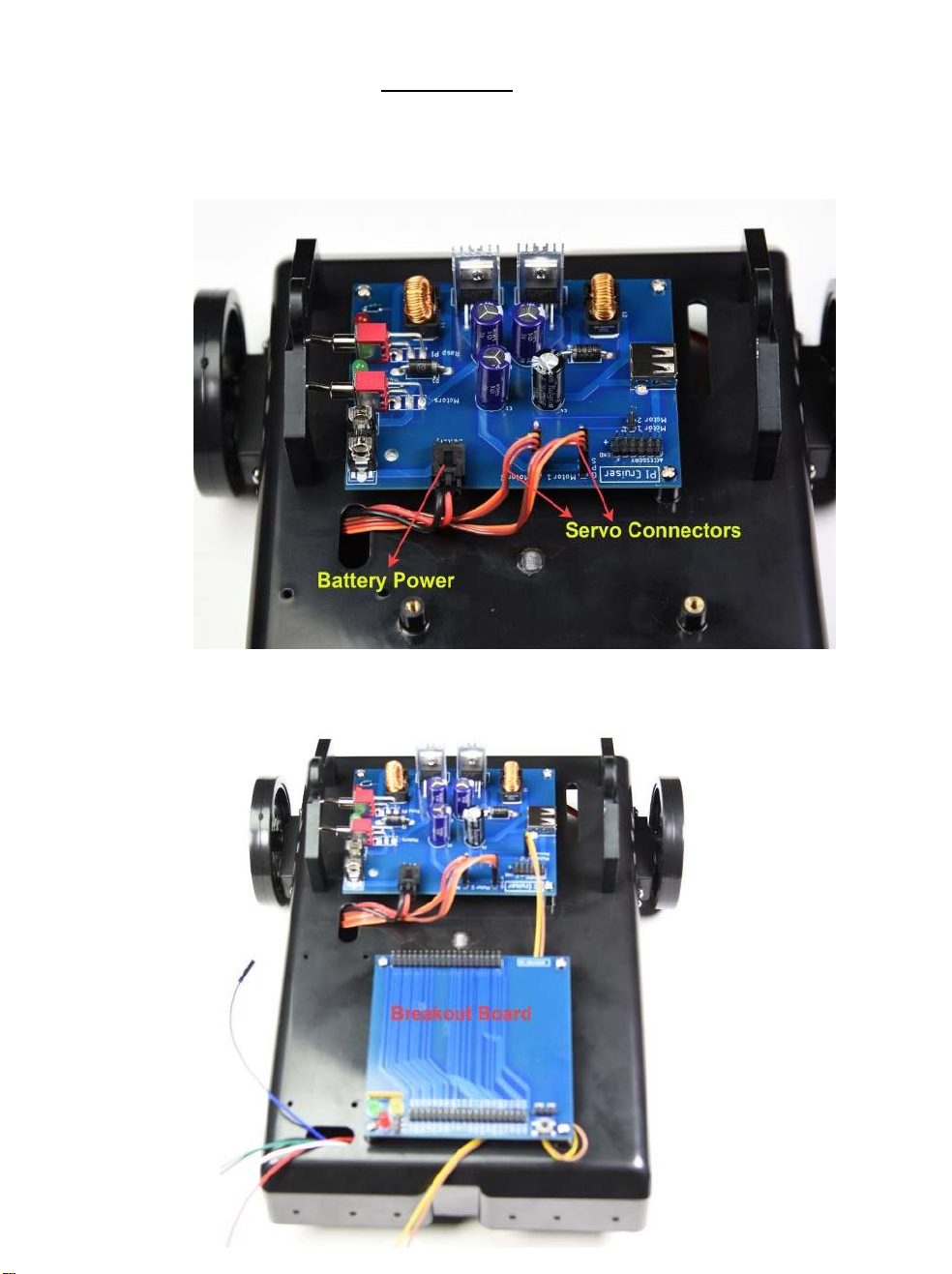
Electronics
• Mount the power board using three or four M3 x 8 screws on the top of the chassis as
shown. Be careful not to damage the electronic components while tightening the screws.
• Connect the servos to the Motor 1 ad Motor 2 ports.
• Connect battery power to the board
• Mount the break out board using four M3 x 8 screws on the top of the chassis as shown.
• Connect two female-female jumper wires to the power board
Page 11

• The servo motors can be attached to any of the two motor ports on the power board. We
will use M1 and M2 corresponding GPIO 13 and GPIO 18.
• Attach the mini-bread breakout board on the available space on the break bard.
Page 12

LCD Screen assembly
• Open the LCD screen and Raspberry Pi from their boxes. Keep the ribbon cable, the
acrylic LCD mount, and the SD card handy. Raspberry Pi not included in the kit.
o Turn over the LCD screen
Page 13
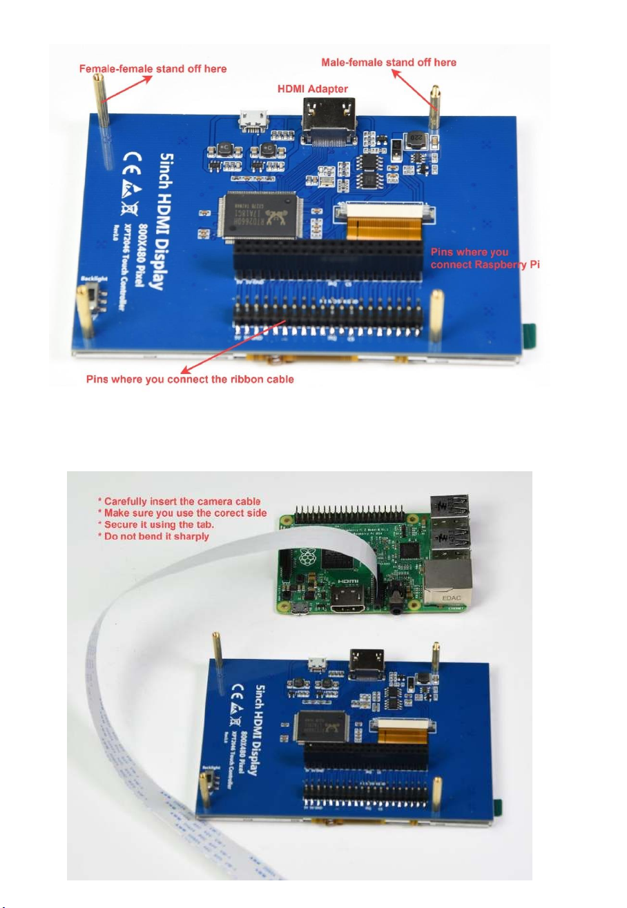
o Attach the three female-female standoffs and one female-male standoff
o Secure the camera cable on your Raspberry Pi properly. Make sure you use the
correct side.
o Route the camera cable as shown (to the left). Do not sharply bend the cable.
Page 14

o Carefully insert the 40-pins of Raspberry Pi onto the LCD screen. Make sure you
are doing it properly, so the HDMI adapter of the Pi and the LCD monitor are
aligned, and the standoff goes through the hole in the board.
o Attach the HDMI adapter connecting the monitor and the Pi.
o Secure the 5 mm standoff.
o Insert the SD card. Make sure you are inserting in the right direction. Forcing he
SD card may damage it.
o Attach the ribbon cable to the male headers on the LCD screen carefully as
shown. If you bend the pins, your screen won’t work.
Page 15

o Route the cable through the slot in the acrylic monitor mount.
o Secure the acrylic mount to the monitor using four M2 x 5 screws.
o Attach the rotating flanges to the brackets using two large thump screws.
o Secure the monitor assembly to the rotating mount using four M3 x 8 screws.
Page 16

Complete the assembly
o Attach the ribbon cable to the male headers on the breakout board. Make sure pins
are aligned before applying pressure. Insert the pins fully.
o Connect the power cable. DO NOT USE ANY OTHER CABLE. This is
a specially designed cable to provide power for Raspberry Pi and the LCD
monitor. Other power cables won’t work. Power cable goes from the USB port on
the power board the micro USB port on the Raspberry Pi board.
The assembly of your basic robot is now complete. If you haven’t already, attach
the two wires coming out of Motor 1 and Motor 2 ports from the power board to
GPIO 13 and GPIO 18 on the breakout board. You can now program your robot to
move. You can use the breadboard area to create your circuits.
Page 17

Ultrasonic sensor and LEDs Assembly
• Find the ultrasonic sensor, sensor plate, LED holders, two LEDs and keep them ready.
o Install the ultrasonic sensor in the mount using our M1.6 x 6 screws and nuts as
shown. These screws and nuts are very tiny so you can easily lose them. You
need the smaller screw driver for this step. You can accidentally drop the nut
or a screw and may never find it so watch out. Be careful not to damage the
electronic components on the back side of the ultrasonic sensor. This can happen
when you use a plier to hold the nut in pace.
o Attach two LEDs using the LED holder to the ultrasonic sensor mount. First insert
the LED holder from the front of the mount. Insert the LED from the back of the
mount with a slight push.
o Secure the ultrasonic sensor-LED assembly to the chassis using two M3 x 10
screws and nuts. You can mount this assembly in any of the three location on the
front side or back side. Depending upon where you mount, you may need to use
longer wires for the sensor and the LEDs.
Page 18

Camera Assembly (Camera not included in the kit)
• Raspberry Pi camera is very sensitive to static electricity. Make sure you ground yourself
before handling the camera.
o Mount the camera unit on the plate using four M2 x 5 screws and nuts. Handle
the camera gently and don’t apply too much pressure when you are securing.
Make sure the camera cable slot is facing down.
Page 19

o Secure the camera assembly to the chassis using two M3 x 10 screws and nuts.
Your robot is now ready for programming fun.
Page 20

Ultrasonic sensor - wiring diagram
Wiring line sensor array - wiring diagram
 Loading...