

Page 1

Raspberry Pi Compute Quick Start Guide
Introduction
Please read this quick start guide carefully before unpacking the boards from their antistatic bags
or using the kit, as it contains important information on how to avoid damage to the Compute
Module and/or IO Board.
Static Sensitivity
Both the Compute Module and Compute Module IO Board can be damaged by static electricity
(electrostatic discharge or ESD). Please take adequate precautions against static discharge during
handling.
Development Kit Contents
The Raspberry Pi Compute Module Development Kit should contain the following:
1 x Quick start sheet (you’re reading it!)
1 x Raspberry Pi Compute Module (CM)
1 x Raspberry Pi Compute Module IO Board (CMIO)
1 x Raspberry Pi CMIO to Raspberry Pi Camera adaptor board
1 x Raspberry Pi CMIO to Raspberry Pi Display adaptor board
2 x 22 way 0.5mm FFC cables (for use with camera and display adaptor boards)
1 x 5V @ 2A power supply
1 x USB A to micro B data cable
Initial Setup and Checks
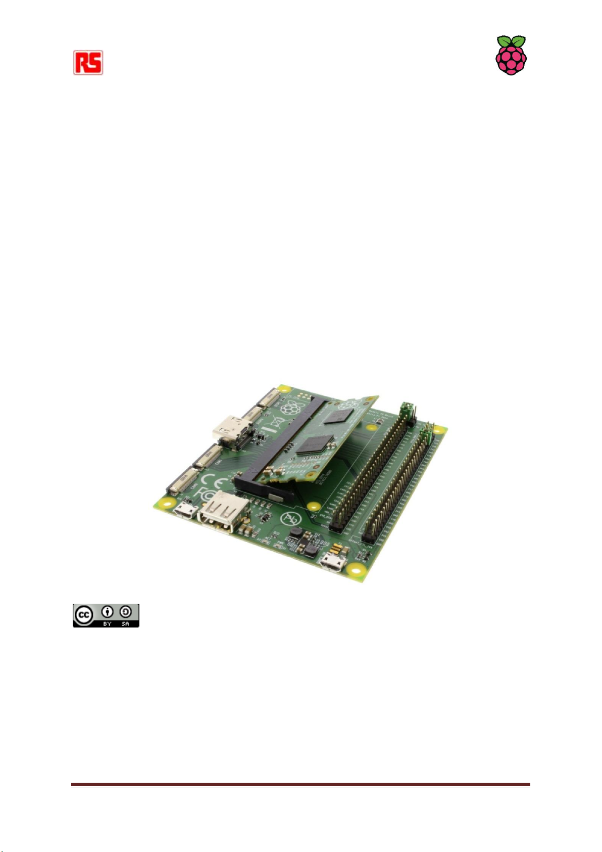
Inserting the Compute Module into the IO Board
Insert the CM at an angle to the IO board (see picture), then gently press down on both top corners
of the module (where the holes are) until the module clicks into place.
I/O Bank Voltage Select Jumper Links
Make sure the two jumper links that select the GPIO bank 0 and 1 voltages are present on header J3
(and set to the voltage you wish to use). Do not power up the board if these jumpers are not in
place (and hence the GPIO bank(s) are unpowered) as this may damage the module.
Raspberry Pi Compute Quick Start Guide Rev 1.0
Page 2
Powering Up
Check the Compute Module is inserted correctly into socket J1. Make sure the GPIO Banks are
powered (Check J3 has jumpers present and set correctly). Attach the micro USB power supply cable
to socket J2 (POWER IN) to power up the board.
At this point the red POWER and green ACT LEDs should light up. Nothing further should happen as
the Compute Module Flash memory [eMMC] is supplied blank and awaits an Operating System of
your choice.
Loading an OS Image and Further Documentation
The next step is to write an Operating System (OS) image to the on-board eMMC Flash memory.
Once this is done the board should boot into the OS at power on.
Further documentation including a step by step guide to Flashing the eMMC is available here:
http://www.raspberrypi.org/documentation/hardware/computemodule/ or download the
Compute Module Hardware Design Guide from: http://uk.rs-online.com/web/p/products/8134164/
Raspberry Pi Documentation by the Raspberry Pi Foundation is licensed under a Creative Commons
Attribution 4.0 International License.
Based on a work at https://github.com/raspberrypi/documentation.
This document is being continually updated. For the most recent information please go to:
github.com/raspberrypi/documentation
Raspberry Pi Compute Quick Start Guide Rev 1.0
 Loading...