

Page 1
FORM TR-499
APPROVED
12028 E. Philadelphia St. Whittier , CA 90601 U.S.A (562) 696-8718 FAX (562) 698-3510
TR 3000 SERIES
TR 3000 SERIES
E-Mail: [email protected] Web http://www.riwinc.com
R
T r i p l e B u r n e r D e c o r a t i v e G a s L o g A p p l i a n c e
A s s e m b l y , I n s t a l l a t i o n , a n d O p e r a t i o n I n s t r u c t i o n s f o r
R a s m u s s e n T r i p l e B u r n e r D e c o r a t i v e G a s A p p l i a n c e M o d e l s :
18" Match Lighted (PA, PR, MA, NA, XF, WSA, LS,UA)(18)/(XF, LS)(21)/(PA, MA, NA, WSA,UA)(24Z)-TR18-J-(N)
18" Manual Pilot Control (PA, PR, MA, NA, XF, WSA, LS,UA)(18)/(XF, LS)(21)/(PA, MA, NA, WSA,UA)(24Z)-TR18-M-(N,P)
18" Switch Pilot Control (PA, PR, MA, NA, XF, WSA, LS,UA)(18)/(XF, LS)(21)/(PA, MA, NA, WSA,UA)(24Z)-TR18-S-(N,P)
24" Match Lighted (PA, PR, MA, NA, XF, WSA, LS,UA)(24)-TR24-J-(N)
24" Manual Pilot Control (PA, PR, MA, NA, XF, WSA, LS,UA)(24)-TR24-M-(N,P)
24" Switch Pilot Control (PA, PR, MA, NA, XF, WSA, LS,UA)(24)-TR24-S-(N,P)
30" Match Lighted (PA, PR, MA, NA, XF, WSA, LS,UA)-(36)-TR30-J-(N)
30 Manual Pilot Control (PA, PR, MA, NA, XF, WSA, LS,UA)-(36)-TR30-M(N,P)
30" Switch Pilot Control (PA, PR, MA, NA, XF, WSA, LS,UA)-(36)-TR30-S-(N,P)
WARNING: If you do not follow these instructions exactly, a fire or
explosion may result causing property damage, personal injury or loss of
life.
Read these Instructions carefully and retain them for future use.
THESE APPLIANCES ARE CERTIFIED TO THE FOLLOWING STANDARDS:
• TR-18; TR-24; TR-30-(M) Manual or (S) Switch: Vented Decorative Appliance ANSI Z21.60/CGA 2.26-M96
• TR-18; TR-24; TR-30-(J) Match Lit: AGA 7-94 (Natural Gas Only)
WARNING: Improper installation,
alteration, service or maintenance can
cause injury or property damage. Read
these instructions thoroughly before
installation. For assistance or additional
information, consult your gas log dealer,
qualified installer, service agency or gas
supplier.
FOR YOUR SAFETY
Do not store or use gasoline or other
flammable vapors and liquids in the vicinity
of this or any other appliance.
FOR YOUR SAFETY
WHAT TO DO IF YOU SMELL GAS
• Do not try to light any appliance.
• Do not touch any electrical switch; do
not use any phone in your building.
• Immediately call your gas supplier from
a neighbors phone. Follow the gas
suppliers instructions.
• If you cannot reach your gas supplier,
call the fire department.
1
Page 2

IMPORTANT INFORMATION
1. This gas log set must be installed only in a solid-fuel burning fireplace with a working flue and constructed of non
combustible material. The flue must exhaust all products of combustion.
2. The minimum permanent free opening of the fireplace chimney or chimney damper must be at least (*Square
Inches - see ITEM 5 below) based on a minimum chimney height of at least 10 feet. The area of the flue must not
be less than 1/10 the area of the fireplace opening.
3. Solid fuels shall not be burned in a fireplace where a decorative appliance is installed.
4. The chimney damper must be fixed in a manner to maintain permanent free opening as outlined in item 2 above at
all times. To accomplish this, install the damper clamp (provided) on the edge of the damper blade to prevent its
closing or drill a hole or holes in the damper.
5. The minimum size (in inches) of the fireplace in which the log set is to be installed must be as follows:
* MINIMUM
LOG
SIZE
18 or 21
24 or 27
30 or 36
6. A fire place screen must be in place when the log set is in operation and, unless other provisions for combustion
air are provided, the screen shall have opening(s) for introduction of combustion air. Glass doors are not certified
with the Log Set. However, if used, Glass Doors must be wide open when the burner is on to allow air for safe
combustion and venting.
7. The minimum inlet gas supply pressure for the purpose of input adjustment shall be 6 inches of water column on
natural gas and 11 inches of water column on LP gases.
8. The maximum inlet gas supply pressure shall be 7 inches of water column on natural gas and 14 inches of water
column on LP gases.
9. The installation and the provision for combustion and ventilation air must conform with the National Fuel Gas Code
ANSI Z223.1 - Latest Edition.
10. The gas log set and its individual shutoff valve must be disconnected from the gas supply piping system during
any pressure testing of that system at test pressures in excess of 1/2 psig (3.5 kPa). The gas log set must be
isolated from the gas supply piping system by closing its individual manual shutoff valve during any pressure
testing of the gas supply piping system at test pressures equal to or less than 1/2 psig (3.5 kPa).
11. The area around the gas log set must be clear and free from combustible materials, gasoline and any other
flammable vapors and liquids.
12. Do not use this appliance if any part has been under water. Immediately call a qualified service technician to
inspect the appliance and to replace any part of the control system and any gas control which has been under
water.
BURNER
SIZE HEIGHT DEPTH WIDTH
18 INCH
24 INCH
30 INCH
18
18
18
14
14
14
30
36
42
CHIMNEY
OPENING
39 SQ IN
51 SQ IN
64 SQ IN
WARNING: CARBON MONOXIDE POISONING MAY LEAD TO DEATH
When used without fresh air, gas log set may give off carbon monoxide, an odorless,
colorless, poisonous gas.
Some people, pregnant women, persons with heart or lung disease, anemia, or under the
influence of alcohol and persons at high altitudes are more affected by carbon monoxide
than others.
Early signs of carbon monoxide poisoning resemble the flu: Headache, dizziness, and/or
nausea. If you have these signs, the gas log may not be installed or working properly, or
the chimney flue may be blocked. GET FRESH AIR AT ONCE! Have gas log set and
chimney flue serviced before using again.
DAMPER MUST BE WIDE OPEN WHILE BURNING
OPEN A WINDOW AN INCH OR TWO FOR
FRESH AIR WHEN USING YOUR GAS LOG
2
Page 3
WARNING! CHECK FOR PROPER VENTING
Damper Stop
Clamp
Damper
Chimney
Flue
A properly sized, unobstructed chimney will normally vent all fumes and products of combustion. Any odor or smoke
detected inside the room is an indication that the flue is not properly removing the combustion products. SHUT
OFF THE BURNER IMMEDIATELY! THE CAUSE OF THE VENTING PROBLEM MUST BE
DISCOVERED AND CORRECTED BEFORE CONTINUED USE OF THE GAS LOG SET . Continued
use with improper venting may cause damage to your fireplace, room and furnishings and could cause serious
illness. If improper venting is suspected , immediately have log set and chimney flue serviced.
Periodically examine and clean the venting system. Once a year, a qualified agency should examine and clean the
venting system of your solid fuel burning fireplace.
THIS LOG SET IS FOR USE ONLY WITH THE GAS TYPE
ATTENTION
ASSEMBLY AND INSTALLATION:
REQUIRED TOOLS AND MATERIALS:
Screw Driver, Adjustable Wrench, Pipe Wrench, Pipe Sealing Compound, Matches.
PREPARATION:
1. This Gas Log set must be INSTALLED IN A FULLY
VENTED METAL OR MASONRY FIREPLACE WITH A
WORKING FLUE THAT IS SAFE FOR BURNING A WOOD
FIRE. The Flue MUST BE FREE OF ANY
OBSTRUCTIONS.
2. Turn off gas supply to fireplace.
3. Clean fireplace floor of any ashes.
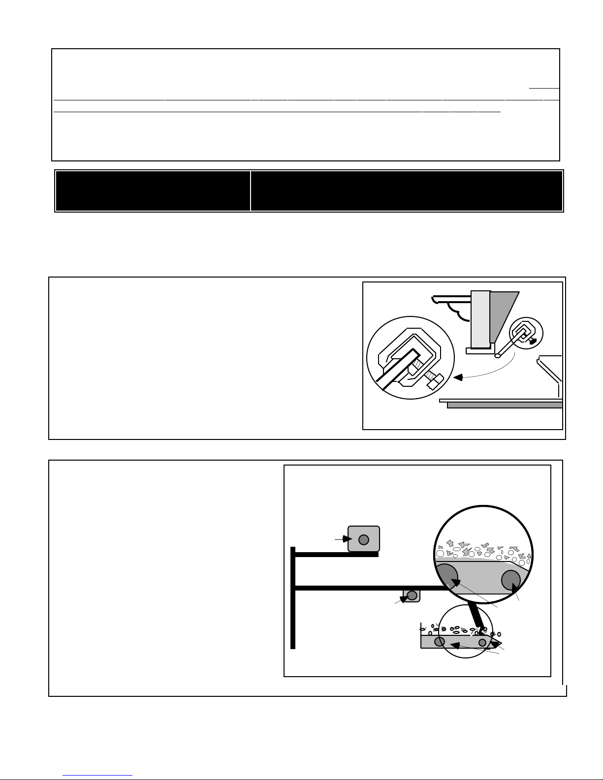
4. Attach damper clamp over edge of fireplace damper blade as
shown. When installed properly, damper clamp prevents accidental
full closure of damper. See FIGURE 1. If unable to install
provided damper clamp, consult IMPORTANT INFORMATION
on front page of these directions.
INDICATED ON THE RATING PLATE.
READ INSTRUCTIONS CAREFULLY BEFORE ASSEMBLY
FIGURE 1
INSTALLING BURNER/GRATE:
1. Place grate/pan/control assembly inside firebox
towards the back of the fireplace. Center grate left
to right.
2. Connect log set to gas supply line. (Do not use
pipe compound on flared connections.)
3. Turn on the gas valve at the supply line in the
fireplace. Check connections for gas leaks by
using a soapy solution. DO NOT USE OPEN
BURNER
FLAME.
4. Completely fill REAR BURNER and MIDDLE
BURNER with Sand (Natural Gas) or
MIDDLE BURNER TRAY
Volcanic Ash (Propane Gas) ensuring that
burner(s) are completely covered with sand.
BURNER
Completely cover both FRONT BURNER TRAY
burners with Sand or Volcanic Ash (as
supplied with your log set.) Sprinkle a light
covering of MIXED EMBER MATERIAL
(vermiculite and ember fiber) over Sand or
Volcanic Ash . (Figure 2).
FRONT BURNER
TRAY
NOTE: Pulling apart Ember Fibers into many very small pieces will increase the glowing ember effect.
FIGURE 2
REAR BURNER
TRAY
MIXED EMBER
MATERIAL
SAND or ASH
BURNERS
BURNERS
3
Page 4
LOG LOCATION:
FRONT LOG
TOP
LOGS
TOP
LOGS
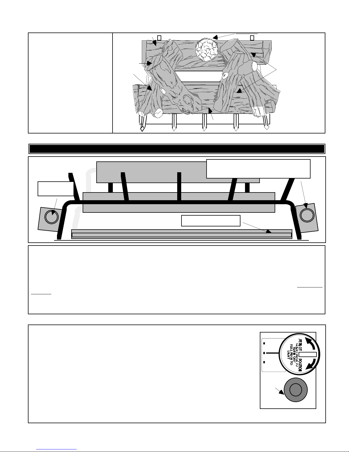
1. Place the FRONT LOG
(the largest log) and REAR
LOG (next largest log) on grate
as shown.
2. Place TOP LOGS and
PINE CONE (if provided) as
shown.
NOTE: To reduce soot
formation on logs, place TOP
LOGs on log stack as shown to
minimize direct contact with
burner flames.
REAR LOG
LIGHTING INSTRUCTIONS:
IMPORTANT! CHIMNEY DAMPER MUST BE WIDE OPEN
PINE CONE
FIGURE 3
REAR BURNER
CONTROL VALVE
(ALL MODELS)
REAR BURNER
MIDDLE BURNER
FRONT BURNER
MATCH PLACEMENT POINT
(MATCH LIT MODELS ONLY)
PRIMARY GAS SUPPLY VALVE KNOB
(MATCH LIT, MANUAL PILOT CONTROL MODELS) OR
CONTROL SELECTOR SWITCH
(SWITCH PILOT CONTROL MODELS)
TR-18; 24; 30-(J) (MATCH LIT) (NATURAL GAS ONLY):
This appliance must be lighted by hand each time it is used. When lighting the appliance, follow these instructions
exactly. Use only your hand to push in or turn the gas control knob. Never use tools. If the knob will not push in or
turn by hand, don't try to repair it, call a qualified service technician. Force or attempted repair may result in a fire or
explosion.
1. Place lighted match on right side of FRONT BURNER TRAY near inlet end of burner (FIGURE 3). DO NOT
HOLD MATCH IN HAND!
2. Slowly open PRIMARY GAS SUPPLY VALVE and wait for burner to light. (FIGURE 3)
3. Adjust PRIMARY GAS SUPPLY VALVE to obtain desired flame height. Ensure adequate gas supply is
available to operate FRONT BURNER TRAY and MIDDLE BURNER TRAY.
TR-18; 24; 30-M-(MANUAL PILOT CONTROL)
PILOT LIGHTING AND OPERATION:
FIGURE 4
1. Slightly push in PRIMARY GAS SUPPLY VALVE knob and turn to
“SEASON/OFF” see (FIGURES 3 & 4).
2. Wait five minutes before lighting.
3. Slightly push knob and turn to “PILOT/OFF”.
4. Depress valve knob until air is bled and gas flows to pilot. Press PIEZZO IGNITOR
BUTTON (FIGURE 4) to light pilot. Continue to hold valve knob in until Pilot remains
lit when knob is released.
5. Slowly turn PRIMARY GAS SUPPLY VALVE knob to “ON”. All three burner's
(FRONT BURNER, MIDDLE BURNER and REAR BURNER) flame height is
controlled by the position of the PRIMARY GAS SUPPLY VALVE knob.
6. If the appliance fails to light or if pilot goes out, repeat steps 1 through 5 above .
7. For complete shutdown, slightly push PRIMARY GAS SUPPLY VALVE
(FIGURE 4) knob in and turn to “SEASON/OFF”.
4
ON
PILOT
OFF
SEASON
OFF
PIEZZO
IGNITOR
BUTTON
PRIMARY GAS
SUPPLY VALVE
Page 5
PILOT
FIGURE 8
PILOT
FLAME
THERMOCOUPLE
1/2 INCH
FLAME
PILOT FLAME ADJUSTMENT
FIGURE 6
Valve Knob
(TR-18; 24; 30-M-(MANUAL PILOT CONTROL):
1/2 INCH
THERMOCOUPLE
FIGURE 5
PILOT ADJUSTMENT:
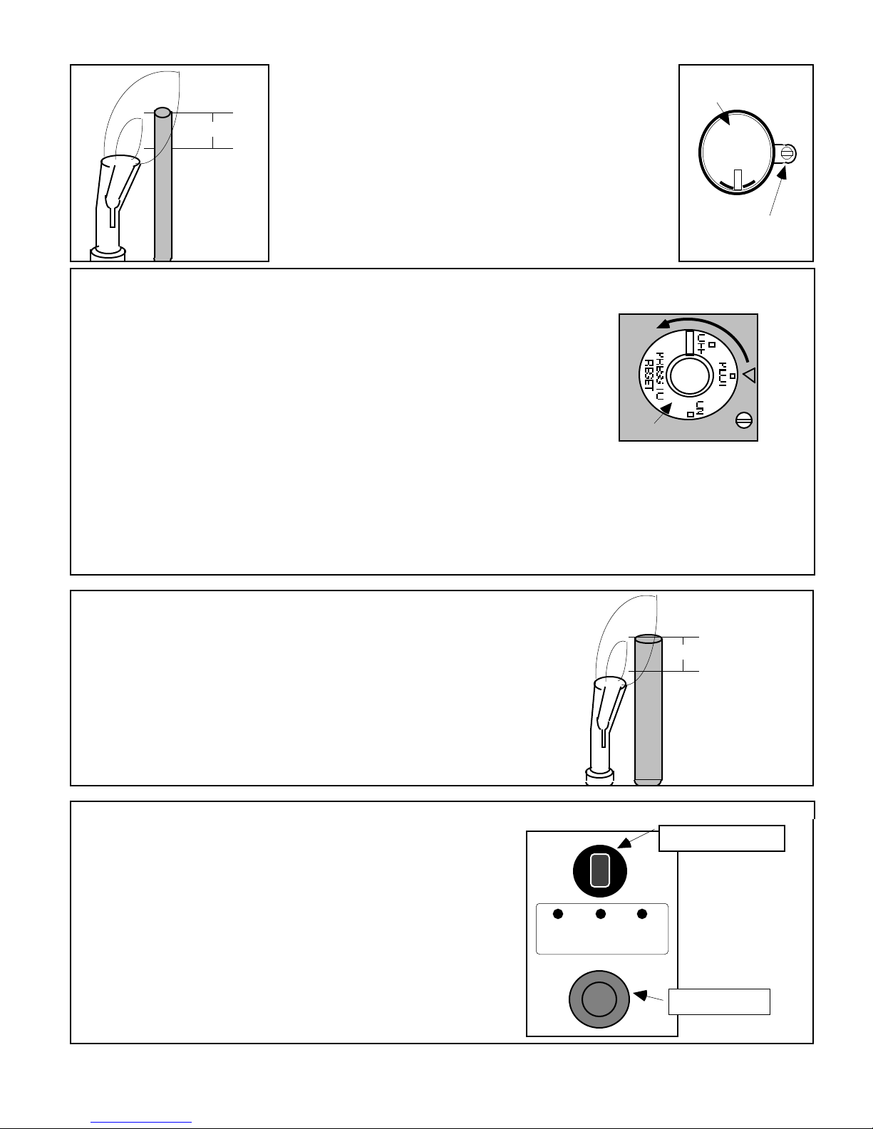
1. Pilot flame should be steady and soft blue surrounding
approximately 1/2 inch of the thermocouple tip. (Figure 5)
2. If adjustment is necessary, use a narrow long stem screw
driver to turn PILOT ADJUSTMENT SCREW (Figure 6).
PILOT ADJUST SCREW. (FIGURE 6) Turn clockwise for
less flame, counter clockwise for more flame.
AT PILOT POSITION
SLIGHT PUSH TO
TURN OFF
FULL PUSH TO
LIGHT
OFF ON
Pilot Adjust
Screw (Located at
base of Valve Stem)
TR-18; 24; 30-S-(SWITCH PILOT CONTROL)
LIGHTING PILOT:
1. Slightly push MILLIVOLT GAS VALVE Knob. Turn clockwise to
"OFF". (FIGURE 7)
2. Put the CONTROL SELECTOR SWITCH into the OFF position.
(FIGURE 7) Accessory Controls must also be turned "OFF". For Remote
Control, put the Remote Receiver Switch in the "OFF" position. For
Thermostat Controlled models, turn temperature dial to "OFF" or to
the lowest temperature setting.
3. Wait at least five minutes to allow gas which may have accumulated
around burner to escape.
4. Slightly push MILLIVOLT GAS VALVE Knob and turn counter
clockwise to "PILOT". (FIGURE 7)
5. Depress and hold MILLIVOLT GAS VALVE knob until air is bled and gas flows to pilot. Press PIEZZO
IGNITOR BUTTON (FIGURE 8) to light pilot. Continue to depress MILLIVOLT GAS VALVE Knob until pilot
remains lit when knob is released (approximately 60 to 90 seconds).
6. If Pilot does not remain lit, repeat steps 1 through 5 and allow more time after Pilot Lighting before releasing
knob.
MILLIVOLT GAS VALVE
Rotate
Valve
Knob
FIGURE 7
PILOT
ADJ
PILOT FLAME ADJUSTMENT (TR-18; 24; 30-S(SWITCH PILOT CONTROL):
PILOT ADJUSTMENT:
1. Pilot flame should be steady and soft blue surrounding
approximately 1/2 inch of the thermocouple tip. (FIGURE 8)
2. If adjustment is necessary, use a narrow long stem screw
driver to turn the PILOT ADJUST SCREW.
PILOT ADJUST SCREW. (FIGURE 8) Turn clockwise for
less flame, counter clockwise for more flame.
BURNER OPERATION (SWITCH PILOT CONTROL IN MANUAL MODE):
1. Turn MILLIVOLT GAS VALVE Knob to "ON" (FIGURE 7).
2. To turn burner on, place the CONTROL SELECTOR
SWITCH in the "ON" position. (FIGURE 9).
3. To turn only the burners off (pilot remains lit), place the
CONTROL SELECTOR SWITCH in the : "OFF" position.
NOTE: All three burner's (FRONT BURNER, MIDDLE
BURNER and REAR BURNER) flame height are directly
controlled by the position of the MILLIVOLT GAS VALVE Knob
(FIGURE 7).
4. Complete Shutdown (Including Pilot): Place Control
Selector Switch in "OFF". Turn "OFF" all Accessory
Switches. Slightly push and turn MILLIVOLT GAS VALVE
Knob to "OFF".
5
SWITCH OFF REMOTE
ON ACCESS
ON
CONTROL SELECTOR
SWITCH
FIGURE 9
PIEZZO IGNITOR
Page 6
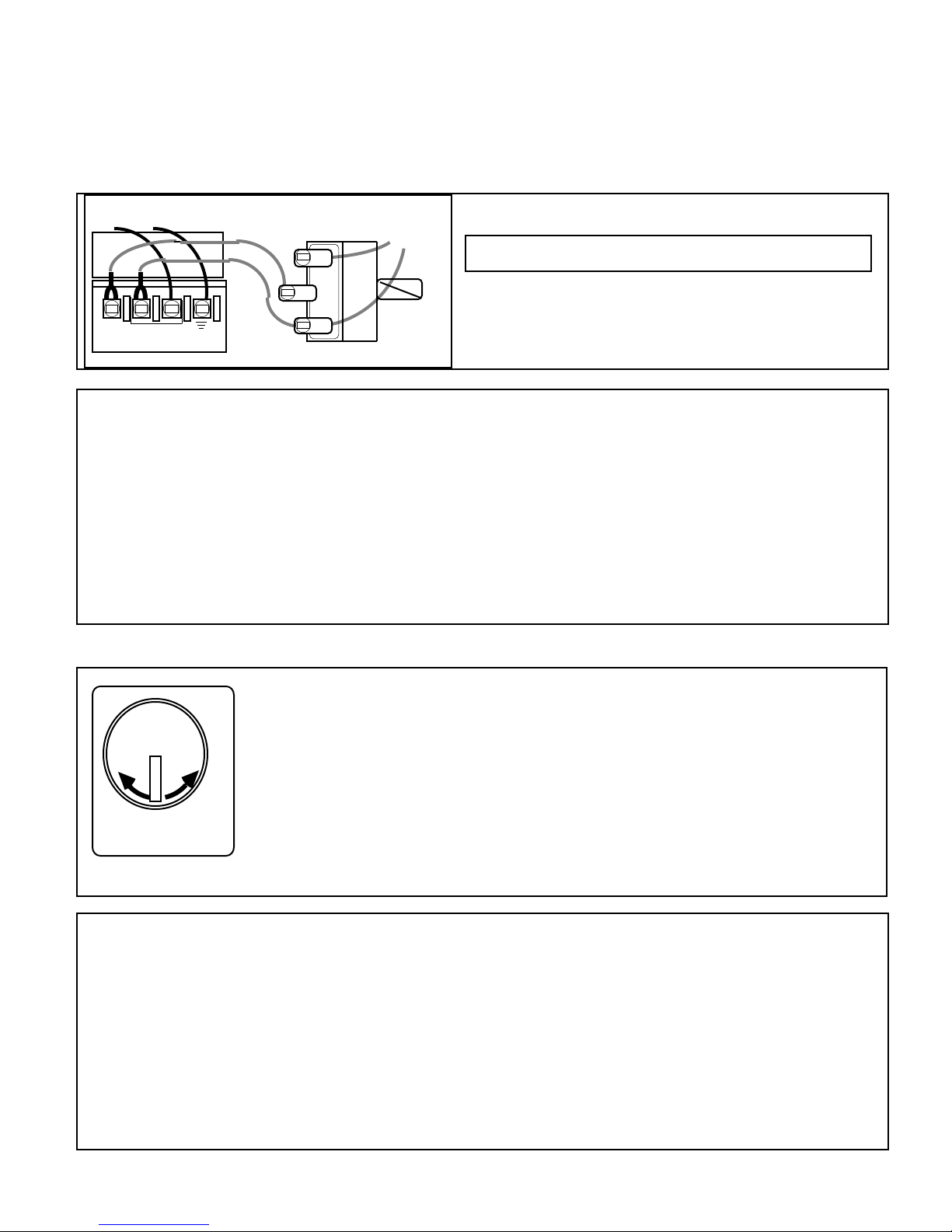
BURNER OPERATION (SWITCH PILOT CONTROL IN ACCESSORY MODE):
FIGURE 10
From THERMOPILE
Valve Terminals
1. Place Control Selector Switch in the "REMOTE ACCESS ON" position. Burner "ON" or "OFF" is now
controlled by the position of the accessory control being used with the burner. Individual operating instructions for
each Accessory Option are included with the individual accessory.
2. Complete Shutdown (Including Pilot): Place Control Selector Switch in "OFF". Turn "OFF" all
Accessory Switches. Slightly push and turn MILLIVOLT GAS VALVE (Figure 7) Knob to "OFF".
Outside Terminal
To
ACCESSORY
CONTROL
SWITCH CONTROL ACCESSORY WIRING :
NOTE: Wire length for Thermostat or Remote or controls
should not exceed 20 feet.
Wiring from the Accessory Control (Remote, Thermostat or
THERMO GEN
Outside Terminal
Control
Selector
Switch
Switch) is connected to the two outside terminals of the
Control Selector Switch as shown in FIGURE 10. Wire
should be 20 AWG Type CL2.
SWITCH CONTROL ACCESSORY OPTIONS:
• Ultra-Sonic Wireless Remote (Model "F10-AB)
• Infrared Wireless Remote With Thermostat (Model "IRRC")
• Wall Switch (Model "WS-1")
• Wall Thermostat (Model "TS-1")
• Wall Timer (60 Minute Timer) (Model "WT-1")
• Crackler Sound Generator option for F10 AB or IRRC (Model "CF5")
Accessory REMOTE LOG HOUSE (Model "RH") is available for use as a heat resistant "log" in which the
receiver portion of Wireless remote option F10 AB or IRRC may be located.
Accessory CRACKLER LOG HOUSE (Model "CH") is available for use as a heat resistant "log" in which the
CRACKLER Sound Generator option for both the F10 AB and IRRC wireless remotes may be located.
REAR BURNER ADJUSTMENT (TOP BURNER CONTROL VALVE):
FIGURE 11
REAR BURNER CONTROL VALVE:
MAINTENANCE and CUSTOMER RESPONSIBILITIES:
Very little maintenance is required. The carbon build-up that results from the gas flame is natural and adds to the
realistic appearance of the set. If carbon becomes excessive it can be lightly brushed or vacuumed away. If
desired, the logs may be removed from the firebox and gently sprayed clean with water. Discoloration from heat is
normal.
Periodically check the pilot burner and main burner flames. The pilot burner should be free of lint and dirt for best
performance. Periodically use a brush with stiff bristles to clean pilot. The main burner should produce a relatively
even flame from side to side. If not, the sand-granules may have become packed and can be loosened by working
a wire or knife blade under the sand or by refilling the pan as described in the section on
ASSEMBLY AND INSTALLATION. Keep area around log set free and clear from debris.
IMPORTANT. From time to time, examine and clean the venting system. Once a year, a qualified agency must
examine and clean the venting system of the solid-fuel burning fireplace.
OFF ON
REAR BURNER
CONTROL VALVE
Once the burners have been lit, the REAR BURNER can be adjusted independently
of the MIDDLE and BOTTOM BURNERS by adjusting the REAR BURNER
CONTROL VALVE (FIGURES 3 & 11)
To achieve the desired flame effect, turn the REAR BURNER CONTROL VALVE
counterclockwise to increase REAR BURNER flame height or clockwise to decrease
the REAR BURNER flame height.
Turning the REAR BURNER CONTROL VALVE to "OFF" will stop all gas flow to
the REAR BURNER CONTROL VALVE only. Gas will continue to flow to the
MIDDLE and BOTTOM BURNERS.
6
Page 7
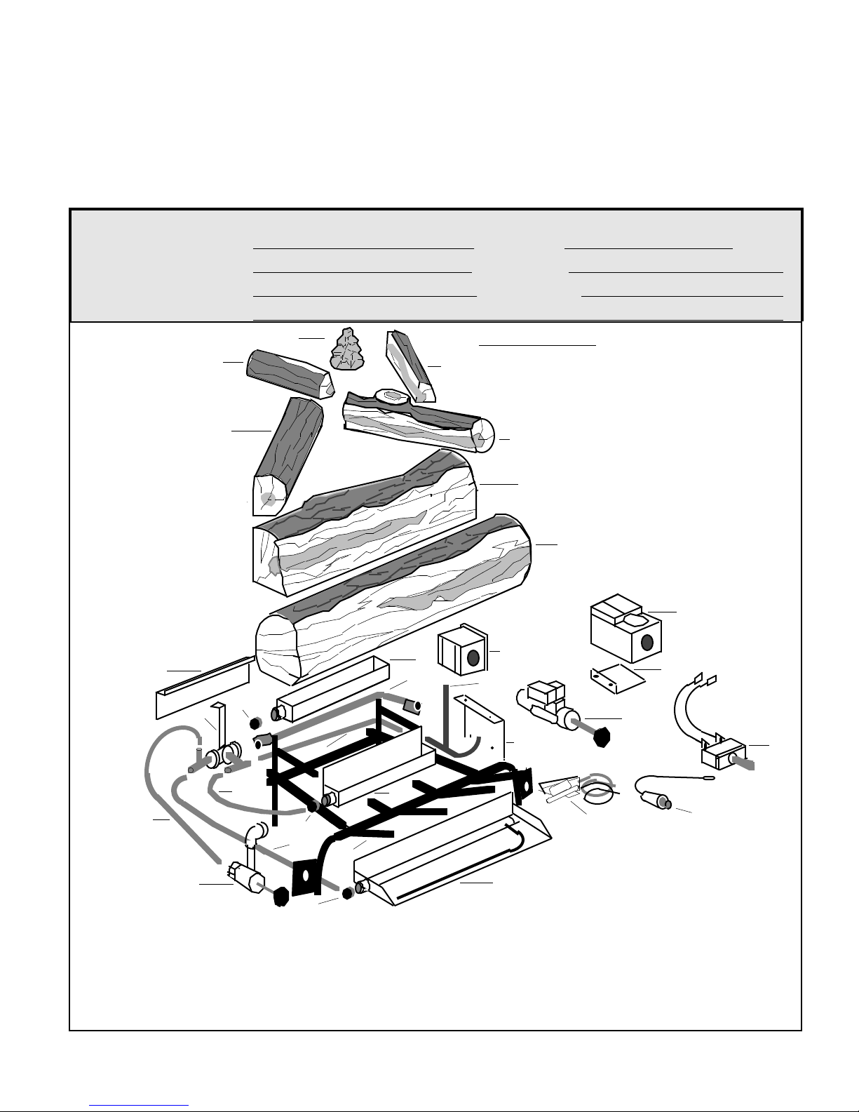
HOW TO ORDER PARTS:
You can order parts through the supplier from whom you purchased your log set. When ordering parts, always specify
the following:
FROM INFORMATION AVAILABLE ON NAME PLATE ATTACHED TO GRATE:
1. Model Number Of The Log Set 2. Serial Number Of The Log Set 3. Type Of Gas (Natural Or L.P. Gas)
FROM PARTS LIST ON PAGE FIVE: The Name Of The Part And Part Number.
MFR BY: RASMUSSEN IRON WORKS, INC.12028 E. Philadelphia Street Whittier, California 90601
SAVE THESE INSTRUCTIONS. FILL IN BLANKS BELOW FOR YOUR PERMANENT RECORD.
CONSUMER RECORD CARD
DATE PURCHASED: MODEL NO.
DATE INSTALLED: SERIAL NO.
INSTALLED BY:
DEALER:
1
2
GAS TYPE:
PARTS LIST
4
12
11
10
3
8
23
9
21
18
19
14
17
20
22
25
5
6
7
29
30
28
24
26
27
31
13
1. Pine Cone 10. Gas Distribution Assembly 17. Grate 23. Primary Connector Tubing
2. Top Log Small (Left) 11. Rear Cover Plate 18. Middle Burner Manifold 24. Control Mounting Plate
3. Top Log Large (left 12. Top Burner Control Valve Tubing 25. Gas Regulator Assembly
4. Top Log Small (Right) Manifold Tubing 19. Middle Burner Orifice 26. Pilot Assembly
5. Top Log (large (Right) 13. Top Burner Control Valve 20. Middle Burner (specify Nat 27. Piezzo Ignitor Assembly
6.. Rear Log 14. Front Burner Manifold or LP) 28. Manual Valve Assembly
7. Front Log Tubing 21. Lighter Tube Connector 29. Switch Valve Assembly
8. Rear Burner 15. Front Burner Orifice Tubing 30. Switch Valve Mount Plate
9. Rear Burner Orifice 16.. Front Burner 22. Lighter Tube 31. Switch Assembly
16
15
7
Page 8

LIMITED LIFETIME CONSUMER PRODUCT WARRANTY
The following warranty has been drafted to comply with the MAGNUSON-MOSS WARRANTY ACT applicable to
products manufactured after July 4, 1975.
It replaces and supersedes any warranty in this package or in any printed literature.
LIMITED WARRANTY:
RASMUSSEN IRON WORKS INC, 12028 E. Philadelphia
Street, Whittier California, U.S.A.., Warrants this Gas Log
Set and accessories against defects in materials and
workmanship, and suitable for a particular purpose, for a
period of:
(1) LOG CASTING - All logs are guaranteed against
burnout in the original installation for the lifetime of the
initial purchaser.
(2) BURNERS/GRATES - 2 years from date of purchase.
(3) SAFETY CONTROLS - Pilots and safety controls are
covered by warranty of the original manufacturer only.
THIS WARRANTY IS FOR THE BENEFIT OF
THE ORIGINAL PURCHASER.
WARRANTY ADJUSTMENT:
(1) RASMUSSEN agrees to repair or furnish a
replacement for, but not remove or install any product or
component which proves defective within the above
warranty and appropriate time periods stated.
(2) BUYER shall notify RASMUSSEN of any defect within
this warranty no later than thirty (30) days after a defect is
discovered.
(3) No product will be accepted for return or replacement
without written authorization of RASMUSSEN. Before
returning merchandise, write to RASMUSSEN giving full
details of the complaint and a copy of sales receipt or
other evidence of purchase date. Merchandise returned
without proof of purchase date will be serviced out-of
warranty at our prevailing service and parts rates. If
merchandise was damaged in transit, file claim
immediately with the carrier. Products returned must be
addressed as follows:
RASMUSSEN IRON WORKS INC
12028 E. PHILADELPHIA STREET
WHITTIER CALIFORNIA 90601
Shipping charges must be pre-paid by the buyer.
REPAIR OR REPLACEMENT UNDER THIS
WARRANTY WILL BE SHIPPED FREIGHT
COLLECT.
EXCLUSIONS FROM WARRANTY:
(1) The foregoing warranty is limited solely as set forth
herein and applies only for the periods designated
above.
(2) RASMUSSEN shall not be liable for any loss,
damage, incidental or consequential damages of any
kind, whether based upon warranty, contract, or
negligence, arising in connection with the sale, use, or
repair of the product. Some states do not allow the
exclusion or limitation of incidental or consequential
damages, so the above limitation or exclusion may not
apply to you.
(3) The maximum liability of RASMUSSEN in connection
with this limited warranty shall not in any case exceed
the contract price paid for the product claimed to be
defective or unsuitable.
(4) This warranty does not extend to any product
manufactured by RASMUSSEN which has been
subjected to misuse, neglect, accident, improper
installation, or use in violation of instructions furnished
by RASMUSSEN.
(5) This warranty does not extend to or apply to any unit
which has been repaired or altered at any place other
than RASMUSSEN IRON WORKS INC factory, or by
persons not expressly approved by RASMUSSEN.
(6) Components manufactured by any supplier other
than RASMUSSEN shall bear only that warranty made
by the manufacturer of that product.
(7) Freight damage, cracking from thermal shock, and
color changes occur from causes beyond
manufacturer's control and are not covered by any
warranty.
THIS WARRANTY GIVES YOU SPECIFIC LEGAL
RIGHTS, AND YOU MAY ALSO HAVE OTHER
RIGHTS WHICH VARY FROM STATE TO STATE.
RASMUSSEN IRON WORKS, INC. shall be held
harmless from any and all claims by the buyer as a result
of injury or damage to an ultimate user or other person
caused by the product sold herein by the seller to the
buyer, whether the injury or damage results from the
assembly, installation, operation, shipment, storage or
manufacture of this product. RASMUSSEN IRON
WORKS, INC. makes no warranties, expressed or
implied, other than those expressly stated herein.
Your Gas Log is designed to burn with a natural smoky yellow flame that produces carbon soot. Like a wood fire,
burning a Gas Log with the flue blocked or closed will cause fumes and smoke to remain in the room and cause
health hazards. DAMPER MUST BE FULLY OPEN WHEN BURNING A GAS LOG SET. Never burn
wood with your gas log set as this will reduce the life of your gas Log Set and will void any warranty.
- CUSTOMER RESPONSIBILITY -
8
 Loading...