

Page 1
Paragon® II
Quick Installation and Setup Guide
Congratulations on your purchase of Paragon II devices comprising of analog Keyboard/Video/Mouse (KVM) switches and
accessory devices that enable users to access and control multiple servers from a set of keyboard, mouse and monitor.
The document provides instructions for basic installation, initial login and channel access. For more detailed information on
the Paragon II products, consult the User Guide accessible from the accompanying User Manuals and Quick Setup
Guides CD or Raritan website's Firmware and Documentation webpage
(http://www.raritan.com/support/firmware-and-documentation/).
Note: The Ethernet port on the Paragon switch is hard coded (not configurable) and supports only 10-BaseT/half duplex.
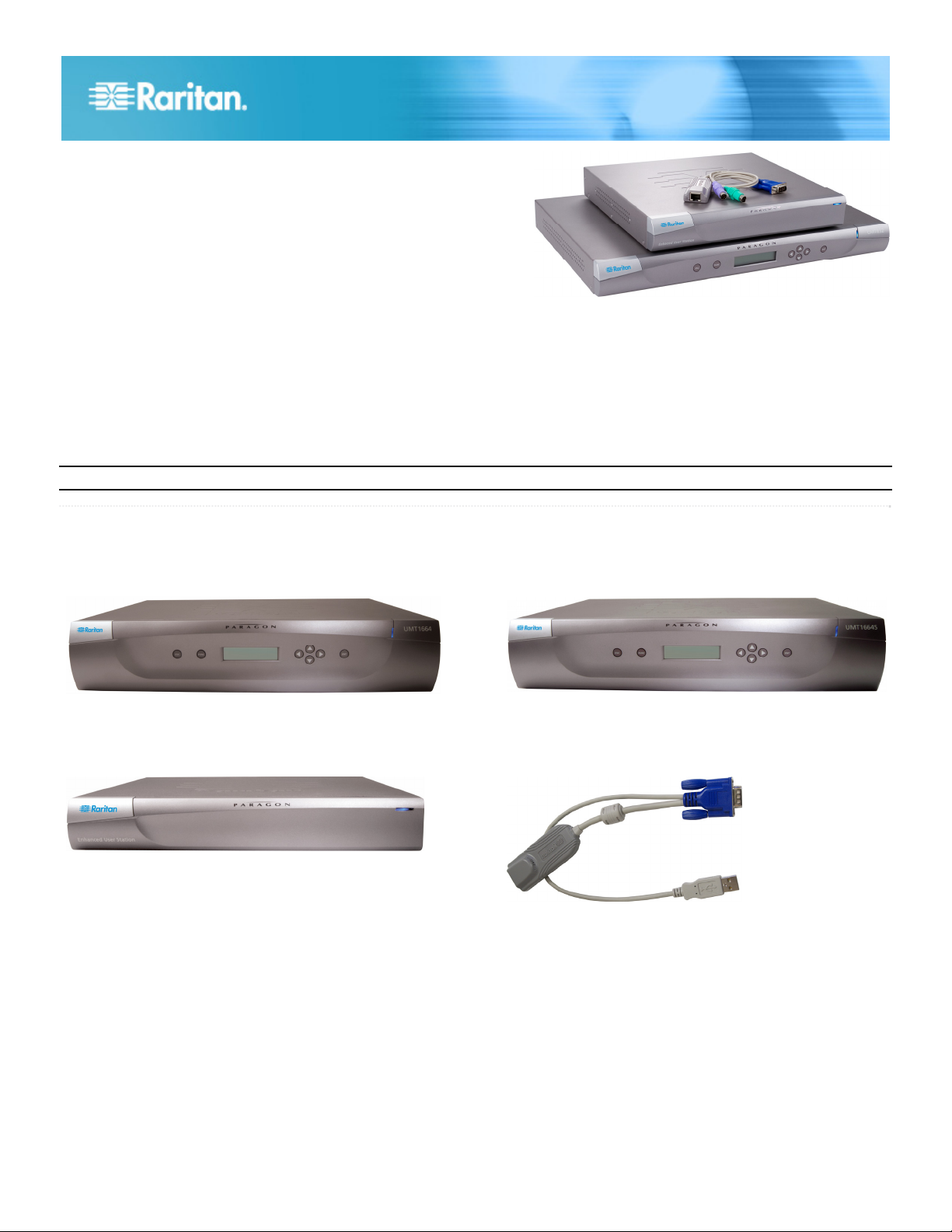
Paragon II cover 4 basic types of devices:
Main Switching Unit (Main Unit)
Models:P2‐UMT242,P2‐UMT442,P2‐UMT832M,P2‐UMT1664M
User Station
Models:P2‐UST,P2‐EUST,P2‐EUST/C
Stacking Unit
Models:P2‐UMT832S,P2‐UMT1664S
Computer Interface Module (CIM)
Models:P2CIM‐APS2,P2CIM‐AUSB,P2CIM‐ASUN,andmore
Paragon II QSG 1
QSG-P2-0J-v4.5-E y 255-30-6010-00
Page 2
Package Contents
Paragon Main Unit (P2-UMT242, P2-UMT442, P2-UMT832M,
or P2-UMT1664M):
• Main Unit x 1
• 20-ft. (6.1-m) Cat5 test cable x 2
• 6-ft. (1.8-m) AC power cord x 1
• Rackmount kit (including brackets and associated screws)
x 1
• Cat5 admin cable x 1
• Raritan's User Manuals & Quick Setup Guides CD x 1
• Quick Setup and Installation Guide x 1
Paragon Stacking Unit:
• Stacking Unit x 1
• RUMT-1U-LM304 or RUMT-2U-LM304 rackmount kit x 1
• 6” stacking cable(s)—the number of cables vary depending
on the model you purchased
P2-UMT832S: Stacking cable x 1
P2-UMT1664S: Stacking cable x 2
• AC power cord x 1
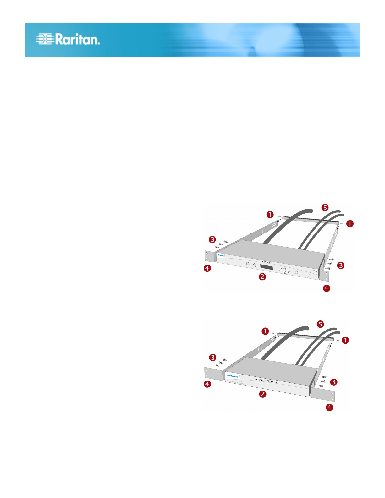
Forward Mount
The steps correspond to the numbers shown in the front
rackmount diagrams.
1. Secure the cable-support bar to the back end of the side
brackets using two of the included screws.
2. Slide the user station or KVM switch between the side
brackets, with its rear panel facing the cable-support bar,
until its front panel is flush with the “ears” of the side
brackets.
3. Secure the user station or switch to the side brackets using
the remaining included screws (three on each side).
4. Mount the entire assembly in your rack and secure the side
brackets' ears to the rack's front rails with your own screws,
bolts, cage nuts, and so on.
5. When connecting cables to the rear panel of the user
station or switch, drape them over the cable-support bar.
Front rackmount of a Paragon switch
Paragon user station (P2-UST, P2-EUST or P2-EUST/C):
• User-station module x 1
• 6-ft. (1.8-m) AC power cord x 1
• 6-ft. (1.8-m) AC power-extension cord for the connected
monitor x 1
• 16.4-ft. (5-m) DB9 male-to-female serial administration
cable x 1
Paragon IP-enabled user station (P2-USTIP1/2):
• IP-enabled user-station module x 1
• 6-ft. (1.8-m) AC power cord x 1
• 16.4-ft. (5-m) DB9 male-to-female serial administration
cable x 1
QS Rule
Rack Mount
Paragon II user stations and most KVM switches can be
mounted in 1U (1.75", 4.4 cm) of vertical space in a standard
19" equipment rack, except that P2-UMT1664M switch shall be
mounted in 2U (3.5", 8.9 cm) of space. To rack-mount a
Paragon switch, use the brackets and screws that came with
the device. To rack-mount a user station, use Raritan's
RUST-LM304 rackmount kit. You can mount a Paragon switch
or user station facing the front of the rack or facing the rear.
Note: If you lose or damage a switch's brackets, replace them
with the RUMT-1U-LM304 kit for any 1U switch or
RUMT-2U-LM304 for a P2-UMT1664M.
Front rackmount of a Paragon user station
Rear Mount
The steps correspond to the numbers shown in the rear
rackmount diagrams.
Paragon II QSG 2
QSG-P2-0J-v4.5-E y 255-30-6010-00
Page 3

1. Secure the cable-support bar to the front end of the side
brackets, near the side brackets' “ears,” using two of the
included screws.
2. Slide the user station or KVM switch between the side
brackets, with its rear panel facing the cable-support bar,
until its front panel is flush with the back edges of the side
brackets.
3. Secure the user station or switch to the side brackets using
the remaining included screws (three on each side).
4. Mount the entire assembly in your rack and secure the side
brackets' ears to the rack's front rails with your own screws,
bolts, cage nuts, and so on.
5. When connecting cables to the rear panel of the user
station or switch, drape them over the cable-support bar.
Rear rackmount of a Paragon switch
Note: Users and servers can be located up to 1000 feet (304 m)
apart. However, try to limit the cable length between the CIM
and Paragon II switch to less than 100 feet (30.5 m) for optimal
video quality, and if possible, limit the total cable length
between the user and target server to less than 500 feet (152 m)
for good video quality.
Step (A): Connect Stacking Units
If your Main Unit supports the use of Stacking Units, such as
P2-UMT832M, you can connect compatible Stacking Units to
expand the number of channel ports in the system.
To connect one or more Stacking Units
1. Connect the power cord to the Main Unit.
2. Connect the power cord to the Stacking Unit.
3. Depending on the Stacking Unit you purchased, use one or
two stacking cables to connect the Stacking Unit to the
Main Unit.
a. For connecting P2-UMT832S to P2-UMT832M:
Plug one end of a stacking cable into the
port—Expansion Port Out—on the Stacking Unit.
Plug the other end of the cable into the
port—Expansion Port—on the Main Unit.
Rear rackmount of a user station
QS Rule
Basic Installation
Ensure that you have turned OFF all servers and Paragon II
devices prior to installation. Installing a basic Paragon II system
involves these steps.
Step (A): Connect Stacking Units to a Main Unit
(Optional)
Step (B): Connect User Stations to the Main Unit
Step (C): Connect Servers to Paragon II Main and
Stacking Units
b. For connecting P2-UMT1664S to P2-UMT1664M:
Plug one end of the stacking cable into "Expansion
Port Out A" on the Stacking Unit and the other end
of the cable into the lower "Expansion Port In" on the
Main Unit.
Plug one end of the other stacking cable into
"Expansion Port Out B" on the Stacking Unit and the
other end of the cable into the upper "Expansion
Port In" on the Main Unit.
4. (Optional) You can cascade up to three P2-UMT832S
Stacking Units for a P2-UMT832M Main Unit. To add more
Stacking Units, follow this procedure:
a. Plug one end of a stacking cable into the
port—Expansion Port In—on the last Stacking Unit
connected to the Main Unit.
b. Plug the other end of the cable into the port—Expansion
Port Out—on the newly added Stacking Unit.
c. Connect a power cord to the newly added Stacking Unit.
Paragon II QSG 3
QSG-P2-0J-v4.5-E y 255-30-6010-00
Page 4

d. Repeat Steps a to c if you w
ant to add one more
Stacking Unit.
5. Turn on all Paragon II device
s.
6. Set the total number of connected Stacking Units on the
front panel of the Main Unit.
a. Press the FUNC
button to activate the Function Menu.
b. Press the U and V buttons to select "Stacking
Support."
c. Press the ENT button to confirm your selection.
d. Press the U and V buttons to select the total numb
Stacking Units—3 maximum for P2-UMT83
er of
2M or 1
maximum for P2-UMT1664M.
e. Press the E
NT button to save the setting.
7. Set a unique Stacking Unit ID on the front panel of each
Stacking Unit.
a. Press the FUNC button to activate the Function M .
enu
b. Press the U and V buttons to select "Set Stack ID."
c. Press the ENT button to confirm yo
ur selection.
d. Press the U and V buttons to assign the numeric ID.
The guideline of ID assignment is:
Assign 1 as the ID for the first Stacking Unit, which
directly connected the Main Unit.
Assign 2 as the ID for the second Stacking Unit,
which is connected to the first Stacking Un
Assign 3 as the ID for the third Stacking
is connected to the second
Stacking Unit.
it.
Unit, which
e. Press the ENT button to save the setting.
8. Turn OFF all Paragon II devices.
9. Turn on the Stackin
Units, turn on the Stacki
g Unit first. If there are multiple Stacking
ng Units from the last one to the first
one in sequence.
10. Turn on the Main Unit.
is
3. Connect a PS/2 or USB keyboard, mouse, and a VGA
monitor to the user station.
Note: P2-EUST/C provides USB ports only for keyboard
and mouse.
4. Turn on the monitor.
5. Repeat Steps 1 to 4 for all other user stations you want to
connect to remaining User Ports.
The user station does not support the use of a VGA-to-DVI
converter.
Step (C): Connect Servers
To connect one or more servers
1. Connect a Paragon II CIM to the Main or Stacking Unit.
a. Plug one end of a Cat5 UTP cable into Channel Port
number 1 on the back of the Main Unit or any connected
Stacking Unit.
b. Plug the other end of the cable into the RJ45 port of the
CIM.
Step (B): Connect User Stations
To connect one or more user stations
1. Connect a user station to the Main Unit.
a. Plug one end of a Cat5 UTP cable into User Port
number 1 on the back of the
b. Plug the other end of the cabl
back of the user station.
2. Connect a power cord to the us
Paragon II QSG
QSG-P2-0J-v4.5-E y 255-30-6010-00
Main Unit.
e into the RJ45 port on the
er station and turn it on.
2. Depending on the CIM model you purchased, plug the
connectors of the CIM into a server's PS/2 or USB
keyboard, mouse, and VGA ports.
4
Page 5

Tip: If the server provides a DVI-D connector instead of a
VGA port, Raritan recommends that you connect the CIM
to the server using a Smart View DVI-to-VGA (female to
female) converter (DV-101). Note that currently only the
Smart View DVI-to-VGA converter has been tested and is
officially supported by Raritan for use with Paragon II.
3. Turn on the server.
4. Repeat Steps 1 to 3 for all other servers you want to
connect to remaining Channel Ports.
QS Rule
Initial Verification
To verify that the server connected to the Paragon
system can be operated:
1. Turn on all devices in the Paragon II system.
2. The Login screen of the On-Screen User Interface (OSUI)
is displayed on the monitor connected to the user station.
3. Type your user name and password in the appropriate
fields and press Enter. For example, if you are the
administrator:
a. Type admin in the User Name field and press Enter.
b. Type raritan (the default password; all lowercase) in
the Password field and press Enter. Note the
password is case-sensitive.
Tip: You can also type any user name for regular users.
The factory-default user names for regular users are
user01 through up to user15, depending on the model of
your Main Unit. By default, there are no passwords for
these user names.
4. The Selection Menu appears.
Channels connecting to servers appear in green. At first
there are no names for any servers so all Name fields are
blank.
Note: The only exception is IBM BladeCenter chassis.
Paragon II shows a default name “IBM-Blade” for the
device.
5. Press Æ or Å on the keyboard to move the highlight to one
of the green channels and press Enter.
6. Now you can view and control the chosen server with the
keyboard and mouse.
7. Press the Scroll Lock key twice QUICKLY to activate the
OSUI, and do one of the following:
To choose another green channel for verification,
repeat Step 5.
To log out of the system, press F9.
QS Rule
Video Gain Adjustment
A video-gain adjustment is available to focus the video image,
which can be especially useful if you are using an LCD
flat-panel monitor. Please note that you must access each
channel individually to adjust that channel's video gain.
To make the video-gain adjustment
1. Press the hot key (default: Scroll Lock) twice QUICKLY to
activate the Selection Menu.
2. Press the + and - (plus- and minus-sign) keys on the
keypad of your keyboard to adjust the video image until it
appears to be in focus.
For P2-UST, the video-gain range is -15 to +15.
For P2-EUST or P2-EUST/C, the video-gain setting is
named "AGC," and its range is 0 to +6.
3. Press Esc or Enter to quit the OSUI and save the video
setting.
4. To adjust another channel's video-gain setting, access it
and then repeat Steps 1 to 3.
QS Rule
Multi-Platform CIM Table
PS/2 CIMs
CIM model PS/2
connector
P2CIM-APS2
P2CIM-APS2DUAL
Paragon II QSG 5
QSG-P2-0J-v4.5-E y 255-30-6010-00
P2CIM-APS2-B
V
V
V
VGA
connector
HD15
HD15
HD15
Local
ports
Page 6

CIM model PS/2
connector
UKVMC
V
VGA
connector
HD15
Local
ports
V
USB CIMs
CIM model USB
connector
P2CIM-AUSB*
P2CIM-AUSBDUAL*
P2CIM-AUSB-B
P2CIM-AUSB-C*
* These USB CIMs also support Sun servers via the SUN USB
ports.
V
V
V
V
VGA
connector
HD15
HD15
HD15
HD15
Local
ports
Serial CIMs
CIM model Serial
(RS-232)
VGA
connector
Local
ports
connector
P2CIM-SER V HD15
CIM model Automatic
skew
compensation
Support
for IBM
Blade
servers
P2CIM-APS2-B V V
P2CIM-AUSB V
P2CIM-AUSBD
V
UAL
P2CIM-AUSB-B V V
P2CIM-AUSB-C V
P2CIM-ASUN V
Support
for card
reader
V
P2CIM-SER-EU V HD15
AUATC V HD15 V
P2CIM-PWR
(for the power strip)
V HD15
SUN CIMs
CIM model SUN MINI
DIN8
VGA
connector
connector
P2CIM-ASUN V HD15
USKVMC V 13w3/
HD15
CIMs with Special Functions
CIM model Automatic
skew
compensation
Support
for IBM
Blade
Support
for card
reader
servers
P2CIM-APS2 V
Local
ports
V
P2CIM-APS2D
UAL
Paragon II QSG 6
QSG-P2-0J-v4.5-E y 255-30-6010-00
V
 Loading...