

Page 1

CommandCenter®
NOC
Administrator Guide
Release 5.4
Copyright © 2006 Raritan Computer, Inc.
CCNOC-0D-E
June 2006
255-80-5301-00
Page 2

This page intentionally left blank.
Page 3

D
Copyright and Trademark Information
This document contains proprietary information that is protected by copyright. All rights reserved.
No part of this document may be photocopied, reproduced, or translated into another language
without express prior written consent of Raritan Computer, Inc.
© Copyright 2006 Raritan, CommandCenter, RaritanConsole, Dominion, and the Raritan
company logo are trademarks or registered trademarks of Raritan Computer, Inc. All rights
reserved. Java is a registered trademark of Sun Microsystems, Inc. Internet Explorer is a
registered trademark of Microsoft Corporation. Netscape and Netscape Navigator are registered
trademarks of Netscape Communication Corporation. All other marks are the property of their
respective owners.
FCC Information
This equipment has been tested and found to comply with the limits for a Class A digital device,
pursuant to Part 15 of the FCC Rules. These limits are designed to provide reasonable protection
against harmful interference in a commercial installation. This equipment generates, uses, and can
radiate radio frequency energy and if not installed and used in accordance with the instructions,
may cause harmful interference to radio communications. Operation of this equipment in a
residential environment may cause harmful interference.
Japanese Approvals
Raritan is not responsible for damage to this product resulting from accident, disaster, misuse,
abuse, non-Raritan modification of the product, or other events outside of Raritan’s reasonable
control or not arising under normal operating conditions.
U
C
LISTE
For assistance in the North or South America, please contact the Raritan Technical Support Team
by telephone (732) 764-8886, by fax (732) 764-8887, or by e-mail
Ask for Technical Support – Monday through Friday, 8:00am to 8:00pm, Eastern.
1F61
US
L
I.T.E.
tech@raritan.com
For assistance around the world, please see the last page of this guide for
regional Raritan office contact information.
Page 4

Safety Guidelines
To avoid potentially fatal shock hazard and possible damage to Raritan equipment:
• Do not use a 2-wire power cord in any product configuration.
• Test AC outlets at your computer and monitor for proper polarity and grounding.
• Use only with grounded outlets at both the computer and monitor. When using a backup UPS,
power the computer, monitor and appliance off the supply.
Default Login User ID/Password
The default username for CC-NOC is admin and the password is raritan. It is recommended to
change this immediately.
Rack Mount Safety Guidelines
In Raritan products which require Rack Mounting, please follow these precautions:
• Operation temperature in a closed rack environment may be greater than room temperature.
Do not exceed the rated maximum ambient temperature of the appliances (see Appendix A:
Specifications).
• Ensure sufficient airflow through the rack environment.
• Mount equipment in the rack carefully to avoid uneven mechanical loading.
• Connect equipment to the supply circuit carefully to avoid overloading circuits.
• Ground all equipment properly, especially supply connections, such as power strips (other
than direct connections), to the branch circuit.
Page 5

FIGURES v
Contents
Chapter 1: Introduction .................................................................. 1
Stand-alone Appliances....................................................................................................................1
Distributed 2500 Series Appliances..................................................................................................1
CommandCenter Secure Gateway (CC-SG) ...................................................................................1
User PC Preparation.................................................................................................................................2
Remote Authentication..............................................................................................................................2
Local Authentication .................................................................................................................................2
Intended Audience............................................................................................................................2
Features Described in this Document ..............................................................................................2
Terminology/Acronyms.....................................................................................................................3
Licensing Explained..........................................................................................................................6
Infrastructure.............................................................................................................................................6
Server.......................................................................................................................................................6
Workstation...............................................................................................................................................7
Promoted Workstation .............................................................................................................................. 7
Chapter 2: General and Advanced Administration ........................ 9
Power Down CC-NOC......................................................................................................................9
Appliance Shutdown/Restart............................................................................................................9
Appliance Network Settings..............................................................................................................9
Configure Date and Time........................................................................................................................10
Configure Network Connection...............................................................................................................11
Change the ISP Gateway Address.........................................................................................................11
Outgoing Email Communication .............................................................................................................12
Change Nameserver Addresses.............................................................................................................13
Network Management Configuration..............................................................................................13
Edit Discovery Ranges............................................................................................................................13
Edit SNMP Ranges.................................................................................................................................15
Configure Scheduled Outages................................................................................................................16
Configure Pollers ....................................................................................................................................18
Manage, Unmanage, Rescan, or Delete Devices...................................................................................19
Configure Performance Thresholds........................................................................................................21
Configure Outage Report........................................................................................................................22
SNMP Reparenting Exclusion List..........................................................................................................23
Associate CommandCenter Secure Gateway (CC-SG).................................................................23
Configure a CC-SG.................................................................................................................................23
Create a CC-SG Peer via a Secure Channel..........................................................................................25
Disconnect a CC-SG...............................................................................................................................26
Delete a CC-SG......................................................................................................................................26
Map CC-SG User Groups to Local User Roles.......................................................................................26
Multi-Site Management...................................................................................................................27
Configure Event Forwarding...................................................................................................................28
Configure Trap Relaying.........................................................................................................................29
Discover a Single Device................................................................................................................30
Edit Performance Thresholds (Per Device)....................................................................................31
Administrator Tools.........................................................................................................................32
Export and Download Configuration Files...............................................................................................32
Download Log Files ................................................................................................................................ 32
Check Disk Utilization on Appliance .......................................................................................................32
Send Incident Report..............................................................................................................................33
Generate Diagnostics File.......................................................................................................................34
Establish Support Connection.................................................................................................................34
Download Data Archives................................................................................................................35
Advanced Administration................................................................................................................35
System Software & Signature Updates...................................................................................................35
Appliance Database Administration........................................................................................................39
Data Backup and Restore.......................................................................................................................39
Manage Routes ......................................................................................................................................40
Prune Unused Performance Data........................................................................................................... 41
Delete Management Settings and Data..................................................................................................42
Delete Traffic Analysis Performance Information....................................................................................42
Install CC-NOC License .................................................................................................................43
Installed Appliances List.................................................................................................................44
Page 6

vi FIGURES
Chapter 3: Configuring Intrusion Detection................................. 45
Configure a Spanned or Mirrored Port...........................................................................................45
Ethernet TAP..................................................................................................................................45
Benefits ...................................................................................................................................................45
Deployment.............................................................................................................................................46
Configure Appliance Home Networks ............................................................................................46
Configure Port Scan Detection.......................................................................................................47
Enable/Disable Signature Types via Signature Profiler..................................................................49
Select Intrusion Detection Appliance(s)..................................................................................................50
Select Types of Signatures to Monitor....................................................................................................51
Load Default Signatures or Settings from Another Appliance.................................................................52
Delete Intrusion Detection Performance Data................................................................................52
Advanced Intrusion Detection Administration.................................................................................53
Manage Signatures.................................................................................................................................53
Upload Custom Signatures Tool.............................................................................................................54
Chapter 4: Configuring Windows Management............................ 55
Windows Management Instrumentation (WMI)..............................................................................55
Configure an External Windows Proxy...........................................................................................55
External Proxy Host Requirements.........................................................................................................56
Overview.................................................................................................................................................56
Download and Run ProxyInstaller ..................................................................................................56
Open Ports on External Proxy Host........................................................................................................57
Configuring the CC-NOC to communicate with the Proxy.......................................................................57
Configuring a WINS Server or LMHOSTS File .......................................................................................62
Authenticate Windows Computers .................................................................................................64
Manage, Unmanage, or Rescan Devices ...............................................................................................64
Configure Windows Performance Thresholds................................................................................65
Configure WINS Server or LMHOSTS File on 2500M ...................................................................65
Edit WINS Settings .................................................................................................................................65
Edit LMHOSTS File.................................................................................................................................67
Chapter 5: Configuring Vulnerability Scanning............................ 69
Accessing Vulnerability Scanning...................................................................................................69
Vulnerability Scan Levels........................................................................................................................70
Specify IP Addresses and Schedule the Scan........................................................................................71
Chapter 6: Configuring Notifications ........................................... 73
Enable/Disable Notifications...........................................................................................................73
Configure Event Notifications.........................................................................................................74
Add/Edit a Notification.............................................................................................................................74
Configure Notification Groups ........................................................................................................78
Add/Modify a Notification Group .............................................................................................................79
Configure Notification Paths...........................................................................................................81
Add/Edit a Notification Path....................................................................................................................81
Configure TAP Paging....................................................................................................................86
Add a new TAP Service..........................................................................................................................87
Edit Modem Parameters.........................................................................................................................88
Revert to Original Configuration.....................................................................................................88
Chapter 7: Managing Assets ........................................................ 89
Manage Assets...............................................................................................................................89
Import Assets..........................................................................................................................................89
Export Assets..........................................................................................................................................91
Map Unassociated Assets to Nodes.......................................................................................................91
Clear All Asset Records..................................................................................................................92
Chapter 8: Creating Users, Categories, Views ............................ 93
Create, Modify, Delete Users .........................................................................................................93
Add a New User......................................................................................................................................93
Edit a User..............................................................................................................................................94
Adding/Editing a Duty Schedule .............................................................................................................95
Configure Categories......................................................................................................................96
Configure Views..............................................................................................................................99
Add/Modify an Existing View.................................................................................................................100
Page 7

FIGURES vii
Map Users ............................................................................................................................................101
Appendix A: Specifications ........................................................ 103
V1 Platform...................................................................................................................................103
General Specifications..........................................................................................................................103
Hardware Specifications.......................................................................................................................103
Remote Connection..............................................................................................................................103
Environmental Requirements................................................................................................................103
Electrical Specifications........................................................................................................................104
Appendix B: Troubleshooting..................................................... 105
The Raritan Support Structure......................................................................................................105
The CC-NOC’s Ability to SSH to Raritan ..............................................................................................105
Checking Appliance Database Settings .......................................................................................106
RAID Array Failure .......................................................................................................................106
The CC-NOC Services .................................................................................................................106
Discovery..............................................................................................................................................106
Capability Scanning..............................................................................................................................107
Pollers...................................................................................................................................................107
Notifications..........................................................................................................................................107
SNMP Data Collection..........................................................................................................................108
Vulnerability Scanning ..........................................................................................................................108
Events, Historic Data, and Graphs........................................................................................................108
Windows Management .........................................................................................................................108
Your Network................................................................................................................................109
Raritan Support Structure.............................................................................................................109
Contacting Raritan................................................................................................................................109
Discovery......................................................................................................................................109
Why Don’t I See the Machine Name for my Windows 2000 Systems?.................................................110
Capability Scanning..............................................................................................................................110
Scanning Interfaces..............................................................................................................................110
Re-Parenting.........................................................................................................................................111
Do the NetBIOS Node Names Match?..................................................................................................111
Are Both IP Addresses in the SNMP Interfaces Table?........................................................................111
Why Can’t My CC-NOC Manage X Service?........................................................................................112
Pollers...........................................................................................................................................112
Notifications..................................................................................................................................113
Why am I Not Receiving Notifications?..............................................................................................113
What Conditions Cause a Notification to be Sent?...............................................................................114
SNMP Data Collection..................................................................................................................114
SNMP – What it is and What it Does....................................................................................................114
Troubleshooting SNMP Data Collection................................................................................................115
GetIF.....................................................................................................................................................116
Vulnerability Scanning..................................................................................................................116
Historic Data and Graphs.............................................................................................................117
How is Performance Data Summarized?..............................................................................................117
How are Service Level Availabilities Calculated? .................................................................................117
Why isn’t SNMP Part of my Service Level Availability Calculations?....................................................117
How Do I Interpret the SNMP Graphs/Reports?...................................................................................118
Additional Support........................................................................................................................118
The Tools Discussed in this Chapter ....................................................................................................118
Documentation......................................................................................................................................118
How do I get Help?...............................................................................................................................118
Appendix C: Performance Monitoring ........................................ 121
Overview.......................................................................................................................................121
SNMP Data Collection..................................................................................................................121
SNMP Data Collection Enhancements.........................................................................................124
Windows Performance Metrics.....................................................................................................124
Leveraging Performance Data in Network Management .............................................................125
Thresholding.................................................................................................................................126
How it works .........................................................................................................................................126
SNMP Performance Metric Thresholds........................................................................................127
Windows Performance Metric Thresholds....................................................................................128
Appendix D: Setting up WMI on Target Machines...................... 129
Page 8

viii FIGURES
Configuring a Windows 98/ME box for Remote WMI Management.............................................129
Configuring a Windows Proxy Details ..........................................................................................130
Registry Changes [configuration]:.........................................................................................................131
Appendix E: Managing and Responding to Intrusion Detection
Events......................................................................................... 133
How the Intrusion Detection works...............................................................................................133
Reducing False Positives with the Signature Profiler............................................................................133
Signature Profiler and the Rules Engine...............................................................................................133
Responding to Events and Notifications ...............................................................................................134
Event Categories..........................................................................................................................134
What do I do when…....................................................................................................................134
What if I have been hacked?........................................................................................................135
Security – An Elusive Goal...........................................................................................................135
Appendix F: Notification Parameters......................................... 137
Notification Parameter Substitution..............................................................................................137
Available values............................................................................................................................137
Notification:...................................................................................................................................137
Events:..........................................................................................................................................137
Assets:..........................................................................................................................................138
Appendix G: Network Traffic Overhead: Network Management’s
Necessary Evil............................................................................ 139
ICMP Pings...................................................................................................................................139
TCP Socket Reachability..............................................................................................................139
HTTP Synthetic Transaction.........................................................................................................140
SNMP Data Collection..................................................................................................................140
Additional Notes............................................................................................................................142
Page 9

FIGURES ix
Figures
Figure 1 Appliance Shutdown/Restart..........................................................................................................9
Figure 2 Configure Date and Time.............................................................................................................10
Figure 3 Configure Network Connection....................................................................................................11
Figure 4 Configure Network Connection....................................................................................................12
Figure 5 Configure Outgoing Email Communication.................................................................................. 12
Figure 6 Configure Nameserver Addresses...............................................................................................13
Figure 7 Edit Discovery Ranges.................................................................................................................14
Figure 8 Edit SNMP Ranges......................................................................................................................16
Figure 9 Defining SNMP Ranges............................................................................................................... 16
Figure 10 Configuring Scheduled Outages................................................................................................17
Figure 11 Edit Scheduled Outages............................................................................................................17
Figure 12 Configure Pollers ....................................................................................................................... 18
Figure 13 Manage, Unmanage, Rescan, or Delete Devices......................................................................20
Figure 14 Device Totals.............................................................................................................................20
Figure 15 Configure Performance Thresholds...........................................................................................21
Figure 16 Configure Outage Report...........................................................................................................22
Figure 17 Navigating to Outage Report .....................................................................................................22
Figure 18 SNMP Reparenting Exclusion List.............................................................................................23
Figure 19 Associate a CommandCenter Secure Gateway.........................................................................23
Figure 20 Configure a CommandCenter Secure Gateway......................................................................... 24
Figure 21 CommandCenter Secure Gateway in Sidebar...........................................................................24
Figure 22 CommandCenter Secure Gateway in Notification Browser........................................................24
Figure 23 Associate a CommandCenter Secure Gateway.........................................................................25
Figure 24 Create a CC-SG Peer................................................................................................................ 25
Figure 25 Disconnect a CommandCenter Secure Gateway ......................................................................26
Figure 26 Delete a CommandCenter Secure Gateway.............................................................................. 26
Figure 27 Map CC-SG User Groups to Local User Roles..........................................................................27
Figure 28 Configure Event Recipients .......................................................................................................28
Figure 29 Adding Event Recipients............................................................................................................28
Figure 30 Configure Event Severities to Forward ...................................................................................... 29
Figure 31 Configure Trap Relaying............................................................................................................30
Figure 32 Specifying Trap Recipient..........................................................................................................30
Figure 33 Discover a Single Device...........................................................................................................30
Figure 34 Configure Performance Thresholds (Per-Device)......................................................................31
Figure 35 Export & Download Configuration Files ..................................................................................... 32
Figure 36 Download Log Files ................................................................................................................... 32
Figure 37 Check Disk Utilization on Appliance...........................................................................................33
Figure 38 Send Incident Report.................................................................................................................33
Figure 39 Generate Diagnostics File..........................................................................................................34
Figure 40 Establish Support Connection via SSH......................................................................................34
Figure 41 Download Data Archives............................................................................................................35
Figure 42 System Updates.........................................................................................................................36
Figure 43 Download Updates.....................................................................................................................36
Figure 44 Install Updates...........................................................................................................................37
Figure 45 View Installed Updates .............................................................................................................. 37
Figure 46 View All Updates........................................................................................................................37
Figure 47 View All Updates........................................................................................................................38
Figure 48 Appliance Database Administration...........................................................................................39
Figure 49 Download Backup Files .............................................................................................................40
Figure 50 Install Backup Files....................................................................................................................40
Figure 51 Manage Routes..........................................................................................................................41
Page 10

x FIGURES
Figure 52 Add a New Network Route.........................................................................................................41
Figure 53 Prune Unused Performance Data..............................................................................................41
Figure 54 Delete Management Settings and Data.....................................................................................42
Figure 55 Delete Traffic Analysis Performance Data.................................................................................43
Figure 56 Install a new License File...........................................................................................................43
Figure 57 Installed Appliances List ............................................................................................................44
Figure 58 Ethernet TAP Deployment.........................................................................................................46
Figure 59 Selecting an Intrusion Detection Appliance for Home Network Configuration............................ 46
Figure 60 Configuring Home Network for Intrusion Detection Appliance ................................................... 47
Figure 61 Selecting an Intrusion Detection Appliance for Portscan Detection ........................................... 48
Figure 62 Configuring Portscan Detection for an Intrusion Detection Appliance........................................48
Figure 63 Selecting Intrusion Detection Appliances for Signature Profiler.................................................50
Figure 64 Selecting Signature Types.........................................................................................................51
Figure 65 Load Intrusion Detection Settings..............................................................................................52
Figure 66 Deleting Intrusion Detection Performance Data.........................................................................52
Figure 67 Selecting an Intrusion Detection Appliance for Changing Signature Set.................................... 53
Figure 68 Generating New Signature Set ..................................................................................................53
Figure 69 Selecting an Intrusion Detection Appliance for Changing Signature Set.................................... 54
Figure 70 Selecting an Intrusion Detection Appliance for Changing Signature Set.................................... 54
Figure 71 Configure an External Proxy for Windows Management............................................................58
Figure 72 Specifying proxy host information..............................................................................................58
Figure 73 Specifying proxy host information..............................................................................................59
Figure 74 Specifying proxy authentication credentials...............................................................................60
Figure 75 List of Windows Management Proxies.......................................................................................61
Figure 76Selecting Internet Protocol (TCP/IP) for WINS Settings..............................................................62
Figure 77Selecting WINS Tab....................................................................................................................63
Figure 78 Change Authentication Usernames and Passwords for Discovered Targets............................. 64
Figure 79 Manage Devices........................................................................................................................64
Figure 80 Configuring Windows Performance Thresholds.........................................................................65
Figure 81 Edit WINS Settings ....................................................................................................................66
Figure 82 WINS Server IP Address ...........................................................................................................66
Figure 83 CommandCenter NOC 2500M Options .....................................................................................67
Figure 84 Edit LMHOSTS File....................................................................................................................67
Figure 85 Vulnerability Scanning Warning.................................................................................................69
Figure 86 Type IP Addresses for Vulnerability Scanning...........................................................................71
Figure 87 Create a Vulnerability Scanning Schedule.................................................................................72
Figure 88 Notification Status......................................................................................................................73
Figure 89 Admin Status .............................................................................................................................73
Figure 90 A Configuring Event Notifications...............................................................................................74
Figure 91 Adding a New Event Notification................................................................................................75
Figure 92 Specifying an Interface/Service Rule for Event Notification.......................................................75
Figure 93 Validating an Interface/Service Rule..........................................................................................77
Figure 94 Entering Notification Recipient Information................................................................................ 77
Figure 95 Special Values for Email Subject and Text Message Fields......................................................78
Figure 96 Arranging Event Notifications.....................................................................................................78
Figure 97 Configure Notification Groups....................................................................................................79
Figure 98 Assigning a Name to a Notification Group.................................................................................79
Figure 99 Assigning Users to a Notification Group .................................................................................... 80
Figure 100 Configuring a Notification Path.................................................................................................81
Figure 101 Configuring a Notification Path.................................................................................................82
Figure 102 Configuring a User Target in Notification Path.........................................................................82
Figure 103 Configuring a Group Target in Notification Path.......................................................................83
Figure 104 Configuring an Email Target in Notification Path......................................................................83
Page 11

FIGURES xi
Figure 105 Modify Notification Paths .........................................................................................................83
Figure 106 Define Escalation in Notification Path......................................................................................84
Figure 107 Configuring a User Target for Escalation in Notification Path ..................................................84
Figure 108 Configuring a Group Target for Escalation in Notification Path................................................85
Figure 109 Configuring an Email Target in Notification Path......................................................................85
Figure 110 Configuring TAP Paging ..........................................................................................................86
Figure 111 Editing TAP Service................................................................................................................. 87
Figure 112 Editing Modem Parameters .....................................................................................................88
Figure 113 Editing Modem Parameters .....................................................................................................88
Figure 114 Importing assets.......................................................................................................................90
Figure 115 Exporting assets ......................................................................................................................91
Figure 116 Mapping unassociated assets to nodes................................................................................... 91
Figure 117 Clear all asset records.............................................................................................................92
Figure 118 Managing users ....................................................................................................................... 93
Figure 119 Adding a New User..................................................................................................................93
Figure 120 Editing a User .......................................................................................................................... 94
Figure 121 Creating/Editing a new user.....................................................................................................94
Figure 122 Create a duty schedule............................................................................................................95
Figure 123 Specifying duty schedule times................................................................................................95
Figure 124 Edit, delete, or reset a duty schedule.......................................................................................96
Figure 125 Configure Categories............................................................................................................... 97
Figure 126 Configure Views....................................................................................................................... 99
Figure 127 Add/Modify Views .................................................................................................................. 100
Figure 128 Map users to views................................................................................................................101
Page 12

xii FIGURES
CHAPTER 1: INTRODUCTION 1
Page 13

Chapter 1: Introduction
The primary function of a CommandCenter NOC (CC-NOC) is to manage nodes in your network.
Nodes are discovered automatically if their IP address is within the managed range of addresses.
In addition to network discovery, a CC-NOC also provides service management, a database of
network information, a rules engine, a notification engine, and a web server. A CC-NOC can also
be instructed to collect statistics from your Windows systems, monitor network traffic for
intrusion attempts and bandwidth performance, and scan your systems for vulnerabilities.
Within this document, the term “CC-NOC” refers to the following models:
• CommandCenter NOC 100
• CommandCenter NOC 250
• CommandCenter NOC 2500N
• CommandCenter NOC 2500M
• CommandCenter NOC 2500S
All configuration tasks are performed on a CC-NOC 100, CC-NOC 250, or CC-NOC 2500N.
Note: When information is related to a particular model, it will be explicitly noted.
Stand-alone Appliances
A CC-NOC can operate in a stand-alone environment where the appliance itself provides
complete functionality, for example, network discovery, polling, windows management, traffic
analysis, vulnerability scanning, and intrusion detection on one box.
These CC-NOC appliances can operate in a stand-alone environment and typically are deployed
in smaller networks or satellite offices:
• CC-NOC 100
• CC-NOC 250
For instructions on deploying and configuring a CC-NOC 100 or CC-NOC 250, see Raritan’s
CommandCenter NOC Deployment Guide.
Distributed 2500 Series Appliances
A CC-NOC can also operate in a distributed environment where the functionality, for example,
network discovery, polling, windows management, traffic analysis, vulnerability scanning, and
intrusion detection is dispersed among different appliances. These CC-NOC appliances can
operate in a distributed environment:
• CC-NOC 2500N: Used for configuration of other appliances, network discovery, polling,
vulnerability scanning, and outages.
• CC-NOC 2500M: Used for Windows Management.
• CC-NOC 2500S: Used for Intrusion Detection and Traffic Analysis.
For instructions on deploying and configuring a CC-NOC in a distributed environment, see
Raritan’s CommandCenter NOC Deployment Guide.
Note: A CC-NOC 2500N can be deployed by itself without a CC-NOC 2500M or CC-NOC 2500S
if the functionality offered by those appliances is not needed.
CommandCenter Secure Gateway (CC-SG)
A CC-SG provides single-point access and control for managed Raritan devices, target servers
and infrastructure devices. A CC-NOC can be deployed in conjunction with a CC-SG. Please see
Raritan’s CommandCenter Secure Gateway Administrator Guide for initial instructions on how to
configure the CC-SG to register for CC-NOC events and to enable the exchange of notifications
between the two appliances.
Page 14

2 COMMANDCENTER NOC ADMINISTRATOR GUIDE
User PC Preparation
To access CC-SG and any targets managed by CC-SG, the browser must have the correct version
of Sun JRE, such as rev 1.4.2.05. See Compatibility Matrix under Firmware Upgrades for CC-
SG on
For CC-SG, pop-up blockers should be disabled as well as any firewall software such as XP SP2
that is enabled by default.
www.raritan.com/support for details.
Remote Authentication
CC-NOC users can be authenticated remotely by CC-SG to provide an enhanced seamless mode
of operation and Single Sign-on (SSO) access to CC-SG targets. With one-click access to CC-SG
and SSO access to targets, a CC-NOC user can move easily between systems.
Mapping of User Groups
With remote authentication, all CC-NOC logins will be securely routed to and resolved by CCSG for remediation. The CC-NOC receives the CC-SG user groups the CC-NOC user is a
member of and maps these groups to any of its local groups, that is, Admin, User, Executive. If a
user belongs to more than one group, the highest privileged group will be used. When a CC-NOC
user accesses a CC-SG target, the access rights, permissions, and policies are based on their user
group membership.
Note: Before mapping the groups on CC-NOC, the user groups must have already been created
on CC-SG or imported from an external authentication server, such as Active Directory.
Local Authentication
By default, CC-NOC users will be locally authenticated if remote authentication is not configured.
Local authentication is also used if remote authentication is configured but the CC-SG is
unavailable or if the password was incorrect.
If “local authentication” is used, then CC-NOC users will have to login to CC-SG to gain access
to targets. They will be prompted for a CC-SG login and password, which will be checked against
the local CC-SG user database.
Note: The admin account on CC-NOC is always authenticated locally, regardless where all other
users are authenticated.
Intended Audience
Three types of users (Administrator, User, Executive User) can access CC-NOC. This document
is intended for users who assume an Administrator role. Administrators perform configuration
tasks on a CC-NOC 100, CC-NOC 250, or CC-NOC 2500N, such as configuring intrusion
detection, windows management, vulnerability scans, etc. Tasks that are available to users with a
User or Executive User role are described in Raritan’s CommandCenter NOC User Guide, which
describes tasks such as viewing intrusion detection events, window management events, etc.
Administrators can also perform all tasks that are available to a User or Executive User.
Features Described in this Document
These features are covered in the following chapters:
• Remote Device Monitoring and Polling (automatic discovery of devices, servers,
workstations)
• Single device Discovery
• Traffic Analysis
• Intrusion Detection
• Windows Management of Servers, Workstations via Windows Management Instrumentation
(WMI)
Page 15

CHAPTER 1: INTRODUCTION 3
• Vulnerability Scanning
• Event Viewing and Searching
• Performance Monitoring per category or device
• Integration with CC-SG where CC-SG is notified of events within the subscribed discovery
range.
• Scheduled Outages
• User, Views, and Category Configuration
• License Upload
• Event, Outage Notification
• Asset Management
• Reports (Outage, Availability, Inventory, Delta Inventory, Vulnerability, Security, SNMP)
• Tools – Network Tools (ping host, port test, trace route to host, profile route to host)
• Tools – Admin Tools (export & download configuration files, download log files, check disk
utilization, send incident report, generate diagnostics file)
• Advanced Admin - Support Tools (Appliance Health, Restore to Factory Defaults,
Backup/Restore Capabilities)
Terminology/Acronyms
Terms and acronyms found in this document include:
• Assets – capital assets in an organization can be tracked. Tracking your assets is useful for
keeping abreast of equipment repairs as well as network or system related moves, additions,
or changes. Asset inventory tracking facilitates generating on-demand reports of hardware
and software to enable greater productivity, financial accountability, and end-user satisfaction.
Asset records can be created manually, imported from a pre-existing list, and exported to a
CSV file for Excel record keeping. Assets can also be associated with a discovered node in
your network.
• CommandCenter Secure Gateway (CC-SG) – single-point access and control for your
managed Raritan devices, target servers, and other network infrastructure devices connected
to CC-SG.
• CSV – comma-separated value files are simple database files that can be easily imported into
a spreadsheet or database program so that you can generate custom reports. This export
functionality is available from any view of the Event Browser.
• DHCP – (Dynamic Host Configuration Protocol). A TCP/IP protocol that dynamically
assigns an IP address to a computer.
• DNS – (Domain Name System). An Internet service that translates domain names into IP
addresses.
• Duty Schedule – is a schedule that reflects a user’s work hours. When a duty schedule is
defined for a user, notifications will be sent to that user only if it occurs within the time frame
that is specified in the duty schedule.
• Events – events include SNMP traps which can be forwarded to third-party tools (HP
OpenView). Events also are generated by components of the Windows operating system and
are recorded in the Events log, for example, Netlogin service, login failures, Windows
Installer. Events are records of significant occurrences in your network, on your systems, or
within the CC-NOC. An event is either outstanding, that is, not addressed nor acknowledged.
The Events Browser allows you to gain insight as to what is going on in the network, whether
it is network management, intrusion detection, or Windows management. Events have
severities – critical, major, warning, normal, cleared, or indeterminate. Intrusion Detection
Events have categories, for example, successful admin privilege gain, and Denial of Service.
Events can be exported in a CSV format for Excel. When an event is triggered, it can send a
notification to a recipient if configured for that recipient. Events can be queried and the
queries can be saved. A CC-NOC allows you to threshold events as well.
Page 16

4 COMMANDCENTER NOC ADMINISTRATOR GUIDE
• ICMP – (Internet Control Management Protocol) ICMP is used by the CC-NOC to discover
devices in your network and is documented in
RFC 792.
• In-band – going through the TCP/IP network to control a target by accessing the target
directly. KVM, Serial, and Generic devices can be accessed via these in-band applications:
RemoteDesktop Viewer, SSH Client, VNC Viewer.
• Intrusion Detection – monitors and analyzes system events for attempts to access system
resources in an unauthorized manner.
• Inventory – see Assets.
• NetBIOS – Network Basic Input/Output System is a program that allows applications on
different computers to communicate within a local area network. It was created by IBM for
its early PC Network, later adopted by Novell and Microsoft. NetBIOS is used in Ethernet,
token ring and Windows NT networks. It does not support a routing mechanism, so
applications communicating on a wide area network must use another "transport mechanism"
(such as TCP/IP) rather than, or in addition, to NetBIOS.
• Network Management – proactively monitors, collects, and maintains all devices and
services on a network.
• Notices – see Notifications.
• Notifications – a notice that is sent to one or more recipients via email, pager, etc. and is
based on an event being triggered. A CC-NOC provides default notifications. You can
control the content of a notification message. A CCNOC evaluates each event against the
configured notifications rules and if it matches one or more rules, a notification is sent. To
receive a notification, a user has to be added to a notification group. Notices can be
outstanding or acknowledged.
• NFS – (Network File System) Standard for accessing files on a remote computer appearing as
a local volume.
• Outage – instances where successive attempted polls of a given service have timed out and a
“node lost service” event was created. Each entry is assigned a unique Outage ID, a
sequential numeric identifier to uniquely identify a given outage. That ID, coupled with the
node label for the node experiencing the outage, the address of the impacted interface, the
service name, and the time the outage occurred are all tracked within the Outages Browser.
At the onset of an outage, all calculations for reporting purposes, for example, Availability
calculations in the Web Console and Availability Report reflect the current service as down
until a future poll is successful. When a service experiencing an outage is successfully polled,
a “node regained service” event will terminate the outage and assign an “Up” date and
timestamp, which is used as the end of the outage for service level availability calculations.
• Out-of-band – using applications such as Raritan Remote Console (RRC), Raritan Console
(RC), or Multi-Platform Client (MPC) to correct or troubleshoot a KVM or serial managed
target in your network..
• Pollers – programs that
collect service information from infrastructure devices and servers,
for example, web, NTP, and email and create service down messages.
• Port Scan – is the probing for openings and availabilities in a network. Attackers generally
use port scanning utilities to probe targets and make a list of all open ports on a device. They
will send specific attacks to open ports hoping to exploit a vulnerability on the target. Port
scanning is detectable by monitoring traffic on the target machine. Scan Level 1 Vulnerability
Scanning uses port scanning methods to search target systems for open ports. However,
normal and legitimate activity, such as DNS and NFS, often resembles the activity of an
attacker executing a port scan against a target and may produce false-positive port scan
events. Those servers performing those services should be excluded from port scanning
activity.
• Proxy host – a system that facilitates connectivity between the CC-NOC and your
managed Windows servers and workstations. The proxy forwards WMI data from the servers
and workstations to the CC-NOC.
• Signature – a fingerprint of network traffic that signals an attack.
• SMB – (Server Message Block) The communications protocol used by Windows-based
operating systems to support sharing of resources across a network to discover systems.
Page 17

CHAPTER 1: INTRODUCTION 5
• SSO – Single Sign-On. With Single Sign-on (SSO) access to CC-SG targets, CC-NOC users
can connect to targets seamlessly, without having to sign onto CC-SG as long as remote
authentication has been configured.
• System Vulnerabilities – unpatched systems, older known vulnerable server daemons on
your system that can be exploited by harmful network traffic.
• TAP – (Telocator Alphanumeric Protocol) A standard protocol enabling modems to send text
messages to pager systems. The CC-NOC can use TAP services to send notifications as text
messages to pagers.
• Users – a CC-NOC has these three types of users:
Administrators who have configuration access to the machine.
Users who have access to everything on a CC-NOC except administrative configuration.
Executive Users who have read-only access to only a few key reports that show the network
health at a high level.
• Views – the combination of categories, for example, Database Servers, Routers, Email
Servers, and Network Interfaces that users will see when logging into a CC-NOC. Views are
customizable and provide a way to map users to the categories that they are most interested in.
• Vulnerability Scan – the CC-NOC can be configured to scan for vulnerabilities, for example,
unpatched systems and older known vulnerable server daemons within a network. Harmful
traffic can be exploited by intruders to gain access to restricted information, can alter the flow
of data through your network, or even disable important services on your network.
Vulnerability scanning provides this type of information about your network
devicesdetection and diagnosis of vulnerabilities, deep detection of all open ports and
services, and logging of all available information that may benefit intruders. Scanning for
vulnerabilities assists administrators in resolving security concerns. For example, an
administrator may decide to apply patches and software updates to fix known security holes,
shut down unwanted or unnecessary services, remove access to sensitive information in your
network, or change security settings and passwords to make them more difficult to crack. For
more information on vulnerabilities, including CVE entries, go to
http://www.cve.mitre.org.
• WMI – (Windows Management Instrumentation) WMI, also known as WBEM, is
Microsoft’s technology for providing a consistent systems management interface to their
platform.
Page 18

6 COMMANDCENTER NOC ADMINISTRATOR GUIDE
Licensing Explained
As devices are discovered in your network, data is collected from the device and the device is
then assigned a license. License types include Infrastructure, Server, Workstation, and Promoted
Workstation. Administrators can change a license from one type to another. The following
explains each license type.
Infrastructure
In order for a device to be assigned an infrastructure license, it must be discovered as a node and
support one of the following "infrastructure" level services:
FTP SMTP Oracle
DHCP LDAP Sybase
DNS MSExchange Informix
NotesHTTP Citrix SQLServer
HTTP-Management DominoIIOP MySQL
HTTPS Router Server
IMAP Switch-Hub POP3
Postgres
An infrastructure device is eligible for the following functionality:
• Capability scans once every 24 hours for new services and/or inventory information
• Service availability polling
• SNMP performance data collection
• SNMP performance thresholding
You can transition a device with an Infrastructure license to any of the following licensed states:
• Workstation
• Server (if the device is a Windows system which supports WMI)
• Promoted Workstation
• Unmanaged
Server
Only Windows systems which support Windows Management Instrumentation (WMI) are
eligible to be assigned a
server system based on its operating system role retrieved via WMI to be auto-licensed as a server.
A server device is eligible for the following functionality:
• Capability scans once every 24 hours for new services and/or inventory information
• Service availability polling
• SNMP performance data collection
• Windows performance data collection
• SNMP performance thresholding
• Windows performance thresholding
You can transition a device with a Server license to any of the following licensed states:
• Workstation
• Infrastructure (if the device is a node)
• Promoted Workstation
• Unmanaged
Server license. In addition to supporting WMI, the system must be a
Page 19

CHAPTER 1: INTRODUCTION 7
Workstation
A Workstation license can be assigned to any type of device, be it a Windows or non-Windows
system. For example, a Linux box which is discovered as a node and which does not support any
of the infrastructure services will be assigned a Workstation license. Similarly, a desktop
Windows system will be assigned a Workstation license.
A workstation device is eligible for the following functionality:
• Capability scans once every 24 hours for new services and/or inventory information
You can transition a device with a Workstation license to any of the following licensed states:
• Server (if the device is a Windows system which supports WMI)
• Infrastructure (if the device is a node)
• Promoted Workstation
• Unmanaged
Promoted Workstation
Promoted Workstation licenses provide a mechanism for you to obtain additional polling and
performance data from a troublesome device on a temporary basis without taking up a Server or
Infrastructure license. The only way for a device to be assigned a Promoted Workstation license
is to assign the license through the web user interface. There are a total of five promoted
workstation licenses available with a CC-NOC appliance.
A promoted workstation device is eligible for the following functionality:
• Capability scans once every 24 hours for new services and/or inventory information
• Service availability polling
• SNMP performance data collection
• Windows performance data collection
• SNMP performance thresholding
• Windows performance thresholding
You can transition a device with a Promoted Workstation license to any of the following licensed
states:
• Workstation
• Server (if the device is a Windows system which supports WMI)
• Infrastructure (if the device is a node)
• Unmanaged
Page 20

8 COMMANDCENTER NOC ADMINISTRATOR GUIDE
Page 21

CHAPTER 2: GENERAL AND ADVANCED ADMINISTRATION 9
Chapter 2: General and Advanced Administration
Power Down CC-NOC
If running CC-NOC on the V1 platform and if it loses AC power while it is up and running, the
V1 unit remembers its last power state. Once AC power is restored, the V1 unit automatically
reboots. However, if a V1 unit loses AC power when it is turned OFF, the V1 unit will remain
powered off when AC power is restored.
Important: Do not hold the POWER button for four or more seconds to forcibly
power down CC-NOC, particularly when CC-NOC is up and running. The
recommended way to power down CC-NOC is to use the following procedure.
To power down the CC-NOC:
1. Remove the bezel and firmly tap the POWER button.
2. Wait for approximately one minute while CC-NOC gracefully powers down. You can
monitor the progress on the console that is attached to the KVM port.
3. If removing the AC power cord, let the power down process completely finish before
removing the power cord. This is required for CC-NOC to complete all transactions, close the
databases, and place the disk drives into a safe state for power removal.
Appliance Shutdown/Restart
The System Shutdown and System Restart buttons are one way that your CC-NOC can be shut
down or restarted. You can also shutdown and restart a CC-NOC while using a serial connection
– see Raritan’s CommandCenter NOC Deployment Guide. While the CC-NOC is designed to be
an appliance, it must store information about your environment in a local database. Thus, it
should be treated with the same sensitivity as a database server. Loss of power or hard shutdowns
of the device can result in database corruption and data loss.
1. Click on the Admin tab in the top navigation bar.
2. Click either System Shutdown or System Restart.
Figure 1 Appliance Shutdown/Restart
Typically, these options are used if you experience a loss of power and need to shutdown the
device while still running off a backup energy source. Contact Technical Support if you have
additional questions regarding these options or your particular situation.
Appliance Network Settings
These are the network settings that can be revisited since they were initially configured with the
serial connection and the First-Time Configuration Wizard – see Raritan’s CommandCenter NOC
Deployment Guide:
• Date and Time
• Network Connection
• ISP Gateway
• Email Communication
• Nameserver Address
Page 22

10 COMMANDCENTER NOC ADMINISTRATOR GUIDE
Configure Date and Time
This page allows you to modify the current time zone and set the local time or configure a
network time protocol (NTP) server with which to synchronize the local time.
Note: If a CC-NOC 250 or 2500N is powered down for more than six hours, upon booting back
up, you will be asked to validate if the time settings are correct.
1. Click on the Admin tab in the top navigation bar.
2. Click Appliance Network Settings.
3. Click Configure Date & Time.
Figure 2 Configure Date and Time
4. Click the radio button Use local date and time and keep current time to leave the local
time as it is.
5. To set the local time on the CC-NOC, click the radio button Use local date and time and set
time. The time will be reset when you continue to the next step.
6. Click the drop-down arrow and select your time zone from the select box. The list is sorted
first by country (two character code), then an order within the country that makes some
geographical sense, and puts the most populous zones first, where that does not contradict the
geographical listing. Please select the zone that is nearest to your location.
7. Click Use NTP servers to turn on the NTP client. NTP is a network service that is used to
synchronize times between computers on a network. You will be required to provide at least
one NTP server if you select this option. If Use NTP servers is currently selected and you
would like to stop using the NTP client, choose either of the two options above depending on
whether or not you want to keep the current time or reset the time.
Note: If you select Use NTP servers, you should install a NTP server in your environment.
8. Click save changes.
Page 23

CHAPTER 2: GENERAL AND ADVANCED ADMINISTRATION 11
Configure Network Connection
This page allows you to change the fixed IP address associated with this appliance. This IP
address was configured when setting up the initial configuration using a serial connection – see
Raritan’s CommandCenter NOC Deployment Guide.
The CC-NOC mimics the traffic generated by a user trying to access various services throughout
the network. This mandates that the CC-NOC also has a network address and other supporting
information to connect to other network devices. DHCP is NOT an alternative, as other devices
will always need to know exactly what address the CC-NOC is using.
Note: Be careful when using this interface as you can render the appliance unreachable via the
network by your users as well as by Technical Support.
1. Click on the Admin tab in the top navigation bar.
2. Click Appliance Network Settings.
3. Click Configure Network Connection.
Figure 3 Configure Network Connection
4. Type network settings, such as TCP/IP address, network mask, and default gateway.
5. Click save changes.
Change the ISP Gateway Address
This page provides a way to manipulate the address monitored for inclusion in the Internet
Connectivity category. The CC-NOC handles your ISP gateway as a special case. If configured
here, your ISP gateway can be monitored for availability and reported on independently. If
applicable, specify the TCP/IP address of your gateway. If you do not have this information, your
ISP should be able to provide it or you can get it by tracing the route to the internet from a
machine on the managed network.
• UNIX Machine: Run
or DNS name that is outside of your local network and appears to belong to your ISP.
Consider the possibility of WAN interfaces showing up in this trace.
• Microsoft Windows Machine: Run
address or DNS name that is outside of your local network and appears to belong to your ISP.
Note: Note that this field is not required. If configured, the ISP gateway takes one infrastructure
license. Type an address of 0.0.0.0 if you do not wish to supply an ISP address.
traceroute www.yahoo.com and look for the first TCP/IP address
tracert www.yahoo.com and look for the first IP
1. Click on the Admin tab in the top navigation bar.
2. Click Appliance Network Settings.
Page 24

12 COMMANDCENTER NOC ADMINISTRATOR GUIDE
3. Click Change the ISP Gateway Address.
Figure 4 Configure Network Connection
4. Type the IP address of the ISP gateway or type an address of 0.0.0.0 if you do not wish to
supply an ISP address.
5. Click save changes.
Outgoing Email Communication
This page provides an interface to change the From: email address in notifications, as well as the
SMTP relay settings. These settings affect how the CC-NOC communicates with you. Keep the
information current and make sure you use valid email addresses to ensure correct status
information reaches the administrator.
To send email notifications, the CC-NOC needs to know how to send email. If allowed, the CCNOC will use its local SMTP service to send email. Some networks, however, will not accept
email from unknown sources. If this is the case, please provide the IP address of an SMTP server
below.
1. Click on the Admin tab in the top navigation bar.
2. Click Appliance Network Settings.
3. Click Outgoing Email Communication.
Figure 5 Configure Outgoing Email Communication
4. To send email notifications, the CC-NOC needs to know how to send email. If allowed, the
CC-NOC will use its local SMTP service to send email. Some networks, however, will not
accept email from unknown sources. If this is the case, provide the IP address of an SMTP
Server in the proper field and select the proper Use section.
5. The email address specified in Send Email As details the email address the underlying
notification mechanisms will use. All mail sent from the CC-NOC, for example, email
notifications will appear as though it is from this address. If you do not provide a value here,
a default will be used (root@
localhost.com).
6. The admin email address specified in Admin Email Address should be the email address of
the person in your organization who will be responsible for CC-NOC administration. This
Page 25

CHAPTER 2: GENERAL AND ADVANCED ADMINISTRATION 13
email address is a required field and will be used to send status information on the CC-NOC
itself.
7. Clicking test SMTP settings sends a test email to the email address specified in the Admin
Email Address field using the specified SMTP server. This test verifies that the CC-NOC
has the proper network connections to be able to send emails.
8. Click save changes.
Change Nameserver Addresses
This page allows you to configure the addresses of your DNS (up to 3) and/or WINS servers.
DNS servers allow systems to translate IP addresses into meaningful names. Please type at least
one DNS server that the CC-NOC can reach efficiently. Place your fastest local servers near the
top of the list.
WINS servers are used in NetBIOS and Windows networking environments to resolve NetBIOS
names across subnet boundaries. If you are managing several subnets that contain machines with
NetBIOS names and have a WINS server that manages the names of the machines, please type
the address of the WINS server in the spaces provided.
1. Click on the Admin tab in the top navigation bar.
2. Click Appliance Network Settings.
3. Click Change Nameserver Addresses.
Figure 6 Configure Nameserver Addresses
4. Type addresses for primary (required), secondary, tertiary DNS servers, and WINS server.
Note: The WINS Server that you can specify here is used by a CC-NOC 100, CC-NOC 250, or
CC-NOC 2500N. This is a separate WINS server that can be configured for a CC-NOC 2500M –
please see
Chapter 4: Configuring Windows Management for additional information.
5. Click save changes.
Network Management Configuration
This page allows you to configure features that affect what network devices you manage and how
you manage them. Network management proactively monitors, collects, and maintains all devices
and services on a network.
Edit Discovery Ranges
This page allows you to modify your initial configuration settings, see Raritan’s CommandCenter
NOC Deployment Guide, determining which specific addresses or address ranges should or
should not be included for discovery. Once discovered, each system is cataloged as either a
Server, Infrastructure, Workstation, or Promoted Workstation device. In this page, you can also
set a flag that determines whether or not any newly discovered devices are automatically licensed
and managed or not. CC-NOC discovers devices via this discovery range, single device discovery
– see section
Discover a Single Device later in this chapter, incoming traps, and through the
Page 26
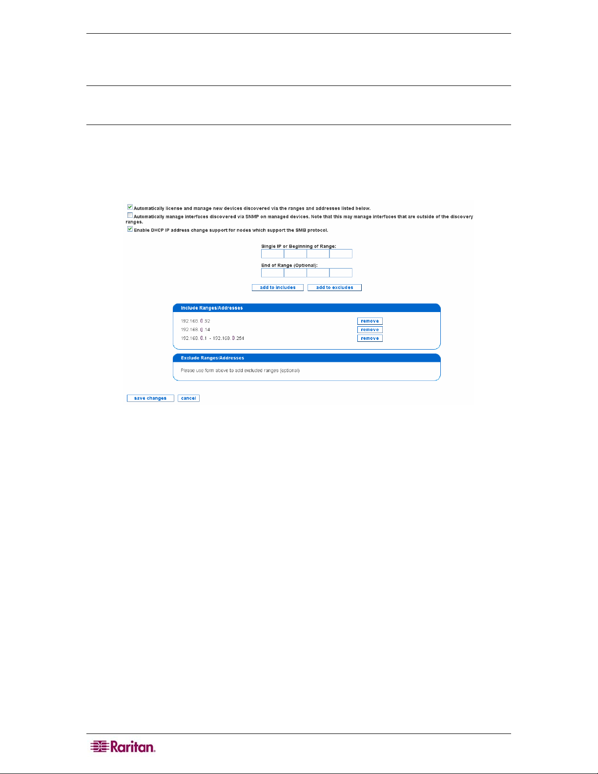
14 COMMANDCENTER NOC ADMINISTRATOR GUIDE
WMI management range – see Specifying Windows Management Ranges in Chapter 4:
Configuring Windows Management for details. Typically, you would want the discovery range
specified here to overlap with the WMI management range.
Note: A CC-NOC discovers devices in the network using ICMP protocol. Once discovered,
further data (for example, operating system) is collected from the device and the device is then
assigned a license, that is, Infrastructure Device license, Server license, or Workstation license.
1. Click on the Admin tab in the top navigation bar.
2. Click Network Management Configuration.
3. Click Edit the Discovery Ranges.
Figure 7 Edit Discovery Ranges
4. Type IP addresses or ranges and click either add to includes or add to excludes– this will
add them to the appropriate list. You can only add one IP or range at a time. If you would like
to remove one from the list, click remove to the right of its listing. When you are done, click
save changes. Use these examples:
• To discover a range, type the first address and the last address and click add to includes.
Ranges may span multiple networks. If there are any ranges or addresses that cannot or
should not be discovered, make sure to add an entry to add to excludes them – see below. If
using CC-SG in conjunction with CC-NOC, this range works with the range configured in
CC-SG – see the CommandCenter Secure Gateway Administrator Guide for details. To stop
CC-NOC from monitoring a device, it can be unmanaged – see section
Rescan, or Delete Devices in
Chapter 2: General and Advanced Administration.
Manage, Unmanage,
• To discover a specific IP address, type the address in "Begin" and leave "End" blank. Click
add to includes to add it to the list. Typically, these are nodes that fall outside of ranges, like
any servers that the company may have co-located off-site.
• To exclude a range, type the first address and the last address and click add to excludes.
Ranges may span multiple networks. In most cases, you will only specify a range that falls
inside of a range you are already including.
• To exclude a specific IP address, type the address in "Begin" and leave "End" blank. Click
add to excludes to add it to the list. It is recommended to exclude DHCP ranges since they
can change IP addresses, which can appear as false outages.
Page 27

CHAPTER 2: GENERAL AND ADVANCED ADMINISTRATION 15
Important! Ensure your discovery range is not too wide, for example, entering
multiple Class B address ranges. This consumes large amounts of resources
and may reduce the performance of CC-NOC. Also, it is recommended to keep
the default “Automatically license and manage new devices discovered via
the ranges and addresses listed below” checked. This avoids devices being
discovered more than once.
5. Click Enable DHCP IP address… for DHCP nodes that support Server Message Block
(SMB), the communications protocol used by Windows-based operating systems to support
sharing of resources across a network, to discover systems. This protocol tracks the nodes by
hostname so if their IP addresses change, it will not generate false outages.
Note: Excludes take priority over Includes. Therefore, if you have an Included range inside an
Excluded Range, the Included range will not be read as included (as you have already excluded
it). To avoid this problem, limit Excluded ranges - example: You have one Server that has an IP
address within a subnet you are not managing. Instead of excluding the whole range and
including that one IP address, build two (2) Exclude lists - one up to that address, and another
starting with the address immediately preceding and going to the end of that range
Example
You can, however, exclude specific IP addresses within an Included range - say for a specific
Server you do not want managed. For example, you include this range of IP addresses:
192.168.0.1 to 192.168.0.255. Within that range, you can specify one IP address we do not want
managed (192.168.0.210). You also included a specific IP outside of the range we specified
(192.168.5.100) to manage. This is a good setup. Where you might run into trouble is if you
excluded a range of IPs that covered the specific IP we listed (say excluding 192.168.5.10 to
192.168.5.150), since the CC-NOC will exclude that range before it includes the specific address
you want to manage.
Edit SNMP Ranges
This page allows you to modify your initial configuration settings (see Raritan’s CommandCenter
NOC Deployment Guide) allowing you to change the mapping of the SNMP community string to
the nodes, that is, specific addresses or address ranges for which it should be used.
The CC-NOC uses the SNMP protocol to collect performance information from devices that
support this protocol, and provides an easy way to view performance graphs of particular devices
on the network.
SNMP implements a security mechanism it calls Community Strings, which are similar to
passwords. The CC-NOC requires the Get Community String, often called the Read-only
Community, to access the SNMP performance metrics. As community strings are configurable on
a per device basis, the number of community strings you may need to enter will vary with the
environment. Many organizations use one community string enterprise-wide, and others maintain
them on a per-device or group of devices basis.
The community strings for any device from which you wish to collect performance information is
required. Review your community definitions below and add, edit or remove community
definitions as needed.
1. Click on the Admin tab in the top navigation bar.
2. Click Network Management Configuration.
Page 28
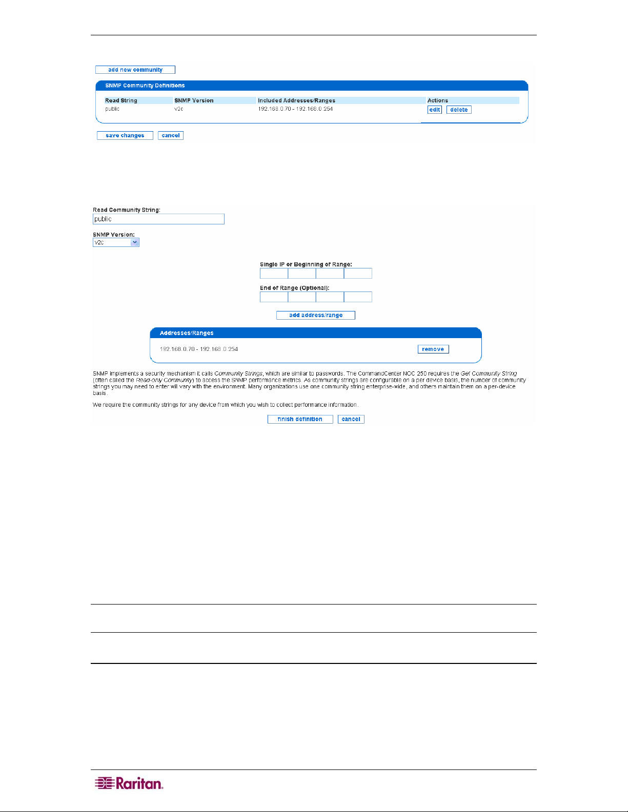
16 COMMANDCENTER NOC ADMINISTRATOR GUIDE
3. Click Edit the SNMP Ranges.
Figure 8 Edit SNMP Ranges
4. Click add new community or edit next to the already defined SNMP range.
Figure 9 Defining SNMP Ranges
5. Edit the community string or add a new one.
6. Specify the SNMP version by selecting v1, v2c, or Not Specified from the SNMP version
drop-down list box.
7. Add ranges or addresses to the community, one at a time. To enter a range, fill in both the
Single IP or Beginning of Range and End of Range fields, and click add address/range.
To enter a single address, simply leave off the End of Range address. Note that you must
provide an IP address or range for each string; if you wish to provide an SNMP string for all
devices that the CC-NOC is managing, just specify the range as 0.0.0.0 - 255.255.255.255.
Click remove if you wish to remove the defined addresses.
8. Click finish definition.
Note: Community Strings are required for any device from which you wish to collect SNMP
performance information. The default SNMP community string is public.
Configure Scheduled Outages
This page allows you to create reoccurring windows where services will not be polled on a
particular node. You can schedule planned outages for managed devices on your network. The
downtime experienced by a device during a scheduled outage will not count negatively against
the uptime statistics measured for the device.
1. Click on the Admin tab in the top navigation bar.
2. Click Network Management Configuration.
Page 29

CHAPTER 2: GENERAL AND ADVANCED ADMINISTRATION 17
3. Click Configure Schedule Outages.
Figure 10 Configuring Scheduled Outages
4. Type a name for the scheduled outage and click add new scheduled outage.
Figure 11 Edit Scheduled Outages
5. Type a name for the scheduled outage.
6. Select a node label, that is, a DNS hostname or IP address, from the Included Node Label
drop-down list and click add. Adding a node label is optional and can be removed once
added.
7. Select an interface, that is, an IP address, from the Included Interfaces drop-down list and
click add. Adding an interface is optional and can be removed once added.
Page 30
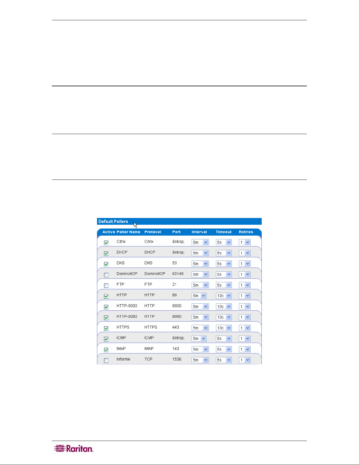
18 COMMANDCENTER NOC ADMINISTRATOR GUIDE
8. Specify an outage window. For outage windows that are set to Recurring Weekly, you cannot
specify outages that start on one day of the week and end on a different day. In these cases
where the outage spans 12:00 AM (Midnight), you should create two outages, one that ends
at 11:59 PM and another that begins at 12:00 AM on the following day. Even though there
appears to be a one minute gap between these outage spans, that is not the case. The outage
will be processed seamlessly.
9. Click add.
Configure Pollers
This page allows you to determine which of the default pollers, that is, the monitors that exercise
your web servers, email servers, etc. and create service down messages should be running on your
system. Also configurable is their behavior, for example, poll attempt timeouts, retry attempts, etc.
Additionally, you can create your own pollers for custom or niche applications you may be
running in your environment.
Note: The SNMP poller is disabled by default because in most cases, the availability of SNMP
data is not integral to the core business of a company, thus it is excluded from availability
calculations. Even if this poller is disabled, SNMP performance collection will still take place
and the SNMP graphs for statistics like network traffic and disk usage will be updated. If the
SNMP service experiences an outage, it may cause gaps in these graphs when data is unavailable
but the outage will not affect your availability statistics.
1. Click on the Admin tab in the top navigation bar.
2. Click Network Management Configuration.
3. Click Configure Pollers.
Figure 12 Configure Pollers
• The Active column shows the current status of the poller. If the active field is checked, the
poller will be scanned in the next poller rescan.
• The Poller Name column shows the name of each service in the poller configuration.
• The Protocol column shows the communications protocol used for polling each service.
• The Port column shows the ports at which the service will be polled.
• This panel also allows the admin user to configure polling intervals, the timeout period
between retries, and number of retries before an outage is declared. Adjusting polling
Page 31

CHAPTER 2: GENERAL AND ADVANCED ADMINISTRATION 19
intervals (they were initially set at 5 minutes for a reason), timeouts and/or retries without
proper planning or forethought runs the risk of:
• Having the pollers get behind
• Adding unreasonable amounts of network traffic in the environment
• Misdiagnosis of outages, in the case of low retries
Note: Raritan strongly recommends that these parameters be adjusted only if change is
absolutely necessary.
4. Enable or disable polling of these services through the check boxes on the left of each row.
5. If you make a change to any of the polling attributes, after you make those changes click
apply changes to commit the changes. This will cause the CC-NOC to restart and set the new
configuration.
6. Clicking add custom poller loads a page that gives you the ability to add named poller
services.
• The Poller Name: column is the name of the new service to be added.
• The Protocol: is the communications protocol used for polling the service. If you simply
want to check to see if the target port is open, then choose "TCP" as the protocol.
• The Port: lists the ports at which the service will be polled. If there is more than one port where
the service can be located, it's recommended to create multiple distinct pollers, each with
unique names, following the model name-####, where the name is the Poller Name and the
# characters are replaced by the port number you intend to poll. After you add the custom
poller, click apply changes on the Configure Pollers page to apply the settings.
• When specifying ports, if there is more than one port where the service can be located, it is
recommended to create multiple distinct pollers, each with unique names, following the
model name-####, where the name is the Poller Name and the # characters are replaced by
the port number you intend to poll.
• If the Make Active field is checked, the poller will be turned on and will scan the network
during the next poller rescan.
7. Click add.
8. After you add the custom poller, click apply changes on the Configure Pollers page to apply
the settings.
Warning: When an administrator adds a new service, the capabilities scanning configuration is
also updated to reflect the new service added and the scan status will be set to “on.”
Manage, Unmanage, Rescan, or Delete Devices
After discovery, the CC-NOC categorized each device as either a Server, Infrastructure device, or
Workstation. This page allows you to change this categorization or remove a device from being
managed by the CC-NOC. For example, you may want to use this page to “promote” a
workstation so that additional metrics, for example, service and performance are collected for it,
similar to a server.
Note: Devices managed to collect WMI information are also displayed in this page – please see
Chapter 4: Configuring Windows Management for additional information.
You can choose to manage or unmanage several devices at once. You can also perform rescans of
several devices at the same time from this page.
1. Click on the Admin tab in the top navigation bar.
2. Click Network Management Configuration.
Page 32

20 COMMANDCENTER NOC ADMINISTRATOR GUIDE
3. Click Manage, Unmanage, Rescan, or Delete Devices.
Figure 13 Manage, Unmanage, Rescan, or Delete Devices
4. Select the devices from the list by clicking in the check boxes.
5. You can change the license type of the selected devices to: Server, Infrastructure,
Workstation, Promoted Workstation, or Unmanaged. Selecting Unmanaged will not
remove it from the list, but will remove its licence, stop sending events to CC-SG if
configured, and decrease network resources since it won’t be polled any longer. Changing it
to Promoted Workstation from Workstation will instruct the CC-NOC to collect
performance and service statistics, similar to that of a server. This requires that it is under
Windows management – please see
Chapter 4: Configuring Windows Management for
additional information. You can have up to five promoted workstations.
6. If you delete one or more device, it is removed from the list but not deleted from the database.
7. You can filter the list by clicking on either Servers, Infrastructure Devices, or
Workstations under Device Totals.
Figure 14 Device Totals
8. You can also produce a report by choosing a format, for example, HTML or XML and click
generate report.
9. Click submit.
Note: If an Infrastructure device, for example, Cisco router is listed as Unknown, it means that
the default sysName value of “Unknown” has not been changed to something more meaningful.
This can be corrected by either clicking the ‘Change Device Label’ link on the device page or the
administrator of the “Unknown” device can assign a meaningful name to the sysName value.
Page 33

CHAPTER 2: GENERAL AND ADVANCED ADMINISTRATION 21
Configure Performance Thresholds
This page displays the current values at which SNMP performance metrics are considered
problematic and events are generated. You have complete control over these thresholds, including
their value, their re-arm values, and the number of consecutive data samples, for example,
"triggers" which must be exceeded before an event is generated.
Note: Performance thresholds are configured for devices with Infrastructure, Server, or
Promoted Workstation licenses.
By configuring performance thresholds, administrators can adjust the high/low thresholds of
certain SNMP performance metrics. This function puts considerable configuration power into the
hands of the administrator – but one that should be used only in the event of clear evidence of
need, for example, environments that have servers that run under a heavy load constantly might
want to increase the high threshold – but only after receiving alarms that do not indicate a
problem. Setting thresholds too low or too high can result in either too many notifications or a
lack of notifications for problems respectively. Thresholds can also be configured on a per-device
basis – see
thresholds override values that are configured here.
Edit Performance Thresholds (Per Device) later in this chapter. Per-device
Please see
Appendix C: Performance Monitoring for additional information.
1. Click on the Admin tab in the top navigation bar.
2. Click Network Management Configuration.
3. Click Configure Performance Thresholds.
Figure 15 Configure Performance Thresholds
The Value column indicates the threshold, which varies by metric, at which an alarm condition of
either “high” or “low” exists, depending upon the metrics of that performance indicator. The
Rearm At column is an indicator of the value at which the threshold alarm will reset, after it has
detected an alarm condition. The Trigger column details how many polling cycles the value must
be above or below the Value level to trigger an alarm. Example: CPU Utilization set at 95.0
Value, 50.0 Rearm, and Trigger at 3 would issue a “High Threshold” alarm if the node had 95% or
higher CPU usage over 15 minutes (3 5-minute intervals). If the Value dropped below 50% either
during or after the initial Trigger, then the alarm would reset and a new alarm would be issued if
the same conditions reappeared.
Note: If the threshold is of type High, the value must be greater than or equal to the Rearm At
value. If the threshold is of type Low, the value must be less than or equal to the Rearm At value.
Page 34

22 COMMANDCENTER NOC ADMINISTRATOR GUIDE
4. Each time you adjust the performance thresholds, click save thresholds to commit the
changes.
5. You can also click reset to restore the threshold values to their pre-set condition.
Configure Outage Report
This page allows you to view and modify the working business hours and days for the Outage
Report. The Outage Report generates two availability percentages:
• One for total availability during the entire week
• Another for availability during business hours
You can edit the time period that is used to calculate the business hours availability by changing
the data in the fields in this page.
1. Click on the Admin tab in the top navigation bar.
2. Click Network Management Configuration.
3. Click Configure Outage Report.
Figure 16 Configure Outage Report
4. Type business hours in 24-hour (military) format.
5. Using the check boxes, select the working days you wish to include in the report.
6. Click apply changes.
7. Click Outage Report in the right-hand side of the page to generate a report.
Figure 17 Navigating to Outage Report
Page 35

CHAPTER 2: GENERAL AND ADVANCED ADMINISTRATION 23
SNMP Reparenting Exclusion List
This page allows you to specify addresses that should be excluded from SNMP reparenting. This
feature is useful if you have multi-interface SNMP devices that have identical IP addresses to
other multi-interface devices.
The most common example of this is if you are managing several routers that each act as
gateways to separate private networks. In this case, all of the routers may have a "192.168.0.1"
interface that acts as a gateway for the private network. Normally, the SNMP reparenting logic
would detect that multiple nodes are sharing an IP address and would collect all of the interfaces
for all of the routers under a single node. By entering "192.168.0.1" in the exclusion list on this
page, you can prevent this from happening and keep all of these nodes separate.
1. Click on the Admin tab in the top navigation bar.
2. Click Network Management Configuration.
3. Click SNMP Reparenting Exclusion List.
Figure 18 SNMP Reparenting Exclusion List
4. Type an IP address you want to exclude from SNMP reparenting.
5. Click add address.
Associate CommandCenter Secure Gateway (CC-SG)
Associating a CC-SG with this appliance allows your users more flexibility when solving issues
by giving them direct out-of-band KVM (Keyboard, Video, Mouse) using RRC, MPC, or RC and
in-band access using SSH Client, VNC Client, or RemoteDesktop Viewer to problem devices.
When a CC-SG is associated with your CC-NOC, your users will have many convenient ways of
accessing managed devices.
Note: Although you may have several CC-SG’s connected to this CC-NOC via a secure
connection, only one can be the remote authentication and authorization source.
Configure a CC-SG
1. Click on the Admin tab in the top navigation bar.
2. Click CommandCenter Secure Gateway Configuration.
Figure 19 Associate a CommandCenter Secure Gateway
Page 36

24 COMMANDCENTER NOC ADMINISTRATOR GUIDE
3. Click add association.
Figure 20 Configure a CommandCenter Secure Gateway
4. Type an IP address or hostname for the CC-SG. This is a required field. If entering a
hostname, it can only contain letters, numbers, periods, or hyphens, and it must begin with
either a letter or a number.
5. Clicking Active will turn on all links to the CC-SG. When Active is not checked, the CC-SG
will be marked as inactive, which will turn off all links to that appliance without removing
the configuration entirely.
6. If you click Enable Link in Sidebar, all normal and administrator users will have a link in
the left-hand sidebar that will take them directly to your CC-SG appliance's user interface.
Note that Executive users do not have access to the CC-SG.
Figure 21 CommandCenter Secure Gateway in Sidebar
7. If you click Enable Link in Notifications, all outgoing notifications will have a convenient
link added that will take your users to your CC-SG appliance's user interface or to the CC-SG
target itself if remote authentication has been configured. This link will also be present in the
Notification Browser and while viewing individual notices.
Figure 22 CommandCenter Secure Gateway in Notification Browser
8. Click save.
Page 37

CHAPTER 2: GENERAL AND ADVANCED ADMINISTRATION 25
Create a CC-SG Peer via a Secure Channel
After configuring the CC-SG with CC-NOC information, for example, specifying its IP address,
and configuring CC-NOC with CC-SG information, you can create a secure channel between CCSG and CC-NOC. Configuring CC-SG with CC-NOC information is documented in the
CommandCenter Secure Gateway Administrator Guide.
Note: To create a valid connection, the time settings on both the CC-NOC and CC-SG should be
synchronized. The best method of achieving this synchronization, it to use a common NTP
(Network Time Protocol) server. For this reason, the CC-NOC and CC-SG are required to be
configured to use an NTP server.
You will either copy and paste the CC-SG passcodes or the CC-SG administrator will submit two
passcodes to you, which you will enter here. Once the certificate exchange process is complete, a
secure channel is established between CC-NOC and CC-SG. The secure channel created here is
available for one year.
1. Click on the Admin tab in the top navigation bar.
2. Click CommandCenter Secure Gateway Configuration.
Figure 23 Associate a CommandCenter Secure Gateway
3. Click connect next to the CC-SG you want to create a secure channel.
Figure 24 Create a CC-SG Peer
4. Either copy and paste the first passcode from CC-SG or type the passcode as supplied by the
CC-SG administrator in Activation Code A.
5. Either copy and paste the second passcode from CC-SG or type the passcode supplied by the
CC-SG administrator in Activation Code B.
6. Click activate. This will start a handshake conversation between the CC-SG and the CC-
NOC. They each will generate and share keys that will uniquely and securely identify each to
the other. Once that handshake is complete, the two appliances will start sharing information.
Page 38

26 COMMANDCENTER NOC ADMINISTRATOR GUIDE
Important! To successfully connect, you must enter the passcodes in CC-NOC
within five minutes after they are generated on CC-SG. This will minimize the
window of opportunity for intruders to breach the system with a brute-force
attack. Avoid transmitting the passcodes over email or other electronic means
to avoid a possible interception by automated systems. A phone call or
exchange of written codes between trusted parties is better protection
against automated interception.
Disconnect a CC-SG
Disconnecting a CC-SG will close the secure channel between CC-NOC and CC-SG. You will
not be able to access CC-SG from CC-NOC.
1. Click on the Admin tab in the top navigation bar.
2. Click CommandCenter Secure Gateway Configuration.
Figure 25 Disconnect a CommandCenter Secure Gateway
3. Click disconnect.
Delete a CC-SG
Deleting a CC-SG will remove all configuration of the CC-SG. Also, if CC-NOC is currently
connected to CC-SG and a secure channel exists, deleting the CC-SG will tear down the secure
channel. You will not be able to access this CC-SG from CC-NOC.
1. Click on the Admin tab in the top navigation bar.
2. Click CommandCenter Secure Gateway Configuration.
Figure 26 Delete a CommandCenter Secure Gateway
3. Click delete.
Map CC-SG User Groups to Local User Roles
If you are using remote authentication via an associated CC-SG, this option allows you to view
all user groups on the remote CC-SG and map them to CC-NOC user roles (Administrator, User,
Executive User).
Note: This assumes that a CC-SG has already been associated with this CC-NOC and that a
secure channel to CC-SG has been established – see section Associate CommandCenter Secure
Gateway (CC-SG) in this chapter for details.
Therefore, when a user remotely accesses CC-SG or a CC-SG target through CC-NOC, their
remote user groups will be checked against this mapping list. For example, you might want to
map a CC-SG "Guest" user group to a CC-NOC "Executive User" role, giving users only access
to the read-only sections of the user interface. Only groups with known mappings will be allowed
access to the CC-NOC.
Page 39

CHAPTER 2: GENERAL AND ADVANCED ADMINISTRATION 27
Important! Configuring these mappings is required in order for remote
authentication to work. Although you may have several CC-SG’s connected to
this CC-NOC via a secure connection, only one can be the remote
authentication and authorization source.
If a user is mapped to a CC-NOC user role but they do not have appropriate permissions to view a
channel on CC-SG as defined in the CC-SG’s user group’s policy, they will not be able to access
the CC-SG target. Therefore, it is important to understand the permissions of the policy that is
applied to a user group on CC-SG. Refer to Raritan’s CommandCenter Secure Gateway
Administrator Guide for details.
If a CC-SG user belongs to multiple user groups, they will be given the highest privileges
possible from all of the groups they belong to. For example, if they belong to a normal "User"
group and an "Administrator" group, they will be given "Administrator" rights.
To map CC-SG user groups to CC-NOC user roles:
1. Click on the Admin tab in the top navigation bar.
2. Click Map Secure Gateway User Groups to Local User Roles. Alternatively, you can click
manage remote authentication from the CC-SG Association window.
Figure 27 Map CC-SG User Groups to Local User Roles
3. For each CC-SG user group, select a CC-NOC user role (Administrator, User, Executive
User) or specify No Mapping.
4. Click save to retain all mappings.
5. To remove all mappings, click clear all mappings and then press save.
6. To reset to initial values, click reset.
Note: The special admin user account is always considered a “local user” and is never checked
remotely.
Multi-Site Management
Multi-Site configuration allows you to configure how to use your Raritan appliances together
over multiple sites. You can forward native Raritan events to other Raritan CC-NOC appliances
or third-party systems. You can also relay all incoming SNMP traps to a third-party system.
Within multi-site management, you can:
• Configure Event Forwarding
• Configure Trap Relaying
Page 40

28 COMMANDCENTER NOC ADMINISTRATOR GUIDE
Configure Event Forwarding
This page allows you to configure the events, for example, SNMP traps you want forwarded to
external systems. It also allows you to configure the external systems to forward the events to.
Within event forwarding, you can:
• Configure Event Recipients
• Configure Event Severities to Forward
Configure Event Recipients
To instruct your CC-NOC to forward copies of its events as SNMP traps to other management
platforms or Raritan appliances, use Configure Event Recipients to specify where your events
should be forwarded.
1. Click on the Admin tab in the top navigation bar.
2. Click Multi-site Management.
3. Click Configure Event Forwarding.
4. Click Configure Event Recipients.
Figure 28 Configure Event Recipients
5. Click add recipient.
Figure 29 Adding Event Recipients
6. Click add recipient.
7. Type protocol, host, and port for the Event Receiver which is the destination address of the
management platform or Raritan appliance you are sending the trap to. On this platform or
appliance resides an SNMP agent that listens for the traps. This Host can be either an IP
Page 41

CHAPTER 2: GENERAL AND ADVANCED ADMINISTRATION 29
address or a hostname that this appliance can resolve. Example: Protocol=Trap, Host=
192.168.51.150, Port=162.
8. Type protocol, host, and port for the Path Back URL which is the IP address or hostname of
this CC-NOC. The Host entered is the web address that a user of the external event recipient
can use to connect back to this appliance via a web browser. The external event recipient
might be on the other side of a firewall, however, and so the URL that a user would use to
access this appliance's web user interface is a required parameter when creating an event
recipient. Currently both HTTP and HTTPS are supported. Example: Protocol=HTTPS,
Host= 192.168.53.176, Port=443.
9. Click save.
Configure Event Severities to Forward
To instruct your CC-NOC to forward copies of its events as SNMP traps to other management
platforms or Raritan appliances, use Configure Event Severities to Forward to specify which
events should be forwarded.
1. Click on the Admin tab in the top navigation bar.
2. Click Multi-site Management.
3. Click Configure Event Forwarding.
4. Click Configure Event Severities to Forward.
Figure 30 Configure Event Severities to Forward
5. Click the check boxes before the Event Severities you want to forward. All events matching
these severities will be forwarded to all recipients specified in Event Forwarding Recipient
– see section
Configure Event Recipients earlier in this chapter. These changes will take
effect immediately.
6. Click save.
Note: For the purposes of event forwarding, the Critical and Cleared severities are equivalent. A
Cleared event occurs when a Critical situation, for example, a network outage has ended.
Configure Trap Relaying
This page allows you to configure where any incoming SNMP traps should be relayed. You can
relay incoming traps to a management platform or Raritan appliance. On this platform or
appliance resides an SNMP agent that listens for the traps.
1. Click on the Admin tab in the top navigation bar.
2. Click Multi-site Management.
Page 42

30 COMMANDCENTER NOC ADMINISTRATOR GUIDE
3. Click Configure Trap Relaying.
Figure 31 Configure Trap Relaying
4. Click add recipient.
Figure 32 Specifying Trap Recipient
5. Specify a hostname that is resolvable from this appliance or an IP address in the Host field.
This can be the same platform or appliance that was specified when configuring event
recipients – see section
Configure Event Recipients earlier in this chapter for additional
information.
6. Type a port, for example, 162 on that host that is listening for incoming SNMP traps.
7. Click save.
Discover a Single Device
This features allows you to enter a single device for immediate entry into the discovery queue.
For example, if a new server has been added to your environment and you want to monitor it
immediately, it can be added here. The discovery process will then determine the characteristics
of this device and map it to an available license type: Infrastructure, Server, Workstation, or
Promoted Workstation. Depending on system load, a single device can usually be discovered
within at least five minutes.
Note: If a device is already discovered, adding the device again will not discover it twice. Only
newly discovered devices are added to the currently managed set of devices.
1. Click on the Admin tab in the top navigation bar.
2. Click Discover a Single Device under Tools.
Figure 33 Discover a Single Device
3. Enter either a NetBIOS name, a hostname, or an IP address.
4. Click discover.
Note: If two devices have the same NetBIOS name, only one will be discovered.
Page 43

CHAPTER 2: GENERAL AND ADVANCED ADMINISTRATION 31
Edit Performance Thresholds (Per Device)
In addition to configuring performance values per category–see section Configure Performance
Thresholds earlier in this chapter, you can also configure performance thresholds on a per-device
basis. Per-device thresholds will override those set per category.
Note: Performance thresholds can be configured on a per-device basis only for devices with
Infrastructure, Server, or Promoted Workstation licenses.
1. Click Search under Device Search in the left-hand corner of the Home page.
2. Click on the IP address of a device with an Infrastructure or Server license.
3. At the top of the window, click Edit Thresholds.
4. This window is displayed.
Figure 34 Configure Performance Thresholds (Per-Device)
The current values at which SNMP, ICMP, HTTP, and/or Windows (WMI) performance metrics
are considered problematic and events are generated for this particular device are listed in the
window. You have complete control over these thresholds, including their value, their re-arm
values, and the number of consecutive data samples (e.g., "triggers") which must be exceeded
before an event is generated.
5. Enter values for Value, Rearm At, and Trigger.
• The Value column indicates the threshold, which varies by metric, at which an alarm
condition of either “high” or “low” exists, depending upon the metrics of that performance
indicator.
• The Rearm At column is an indicator of the value at which the threshold alarm will reset,
after it has detected an alarm condition.
• The Trigger column details how many polling cycles the value must be above or below the
Value level to trigger an alarm.
Example: CPU Utilization set at 95.0 Value, 50.0 Rearm, and Trigger at 3 would issue a “High
Threshold” alarm if the node had 95% or higher CPU usage over 15 minutes (3 5-minute
intervals). If the Value dropped below 50% either during or after the initial Trigger, then the
alarm would reset and a new alarm would be issued if the same conditions reappeared.
Note: If the threshold is of type High, the value must be greater than or equal to the Rearm At
value. If the threshold is of type Low, the value must be less than or equal to the Rearm At value.
6. Each time you adjust the performance thresholds, click save thresholds to commit the
changes.
7. You can also click reset to restore the threshold values to their pre-set condition.
Page 44

32 COMMANDCENTER NOC ADMINISTRATOR GUIDE
Administrator Tools
Administrator tools help you diagnose and fix problems with the CC-NOC. These tools allow you
to backup configuration files, download logs, check the disk usage of your CC-NOC, and
establish connections to Technical Support. Access administrator tools either from the Tools tab
or from the Admin tab.
Export and Download Configuration Files
This page allows you to export the current configuration of the CC-NOC appliance. The
configuration file will be archived in a file called configuration.tgz. This will most commonly be
used at the request of Technical Support. You can then download this file by accessing
http://<CommandCenter_NOC_IP_Address>/public.
1. Click on the Admin tab in the top navigation bar.
2. Click Administrator Tools.
3. Click Export & Download Configuration Files
Figure 35 Export & Download Configuration Files
4. Access http://<CommandCenter_NOC_IP_Address>/public to view the file.
Download Log Files
This page allows you to download system log files, most commonly used at the request of
Technical Support.
1. Click on the Admin tab in the top navigation bar.
2. Click Administrator Tools.
3. Click Download Log Files.
Figure 36 Download Log Files
4. Open a log file to display its contents by clicking on it.
Check Disk Utilization on Appliance
This page allows you to see how much of the internal storage the appliance has used while
collecting information about your network. The storage inside the appliance is sufficient to handle
almost any monitoring tasks but if you are experiencing problems with the device, you may want
to check to make sure that storage space is available.
1. Click on the Admin tab in the top navigation bar.
2. Click Administrator Tools.
Page 45

CHAPTER 2: GENERAL AND ADVANCED ADMINISTRATION 33
3. Click Check Disk Utilization on Appliance.
Figure 37 Check Disk Utilization on Appliance
The Disk Usage section lists the current free space percentages for different areas of the storage
within the CC-NOC appliance. The disk storage inside this CC-NOC appliance is used to store
logs of system activity, performance information for the devices that you are monitoring, and a
database of collected management information that includes event and notification records.
It is possible to exhaust the storage space on this CC-NOC if you are monitoring a number of
devices that exceeds the specifications of the CC-NOC. To clean up the storage space, you can
delete unused data periodically – see section
Prune Unused Performance Data later in this
chapter for additional information.
Send Incident Report
If you experience a problem with the CC-NOC, submit an Incident Report.
1. Click on the Admin tab in the top navigation bar.
2. Click Administrator Tools.
3. Click Send Incident Report.
Figure 38 Send Incident Report
Page 46

34 COMMANDCENTER NOC ADMINISTRATOR GUIDE
4. Type a description of the problem you are experiencing in the text box.
5. Type an email address in Confirmation Email: so that when the incident report email is
received, you will get a confirmation message.
6. Click send incident email.
Generate Diagnostics File
If your CC-NOC does not have email access (an SMTP server has not configured – see section
Outgoing Email Communication), use this option to create an archive that can be downloaded
from the CC-NOC to a computer that does have email access.
The diagnostics file will be archived in a file called diagnostics.tar.gz. You can then download
this file by accessing http://<CommandCenter_NOC_IP_Address>/public.
1. Click on the Admin tab in the top navigation bar.
2. Click Administrator Tools.
3. Click Generate Diagnostics File.
Figure 39 Generate Diagnostics File
4. Access http://<CommandCenter_NOC_IP_Address>/public to view the file.
Establish Support Connection
If you have contacted Technical Support and they have requested SSH access to your appliance,
you can open a Secure Shell (SSH) connection by clicking establish support connection.
Opening the connection may take between 10 to 30 seconds. Your firewall must allow out-going
connections from the CC-NOC on both port 22 (SSH) and port 443 (HTTPS).
1. Click on the Admin tab in the top navigation bar.
2. Click Administrator Tools.
3. Click establish support connection.
Figure 40 Establish Support Connection via SSH
Page 47

CHAPTER 2: GENERAL AND ADVANCED ADMINISTRATION 35
Download Data Archives
Every 24 hours, the previous day’s events are placed into an event archival file and made
accessible. Download this archival file or unzip it to access a comma-separated value (CSV) file,
which can be opened with any spreadsheet application to view the events for that day.
1. Click on the Admin tab in the top navigation bar.
2. Click Administrator Tools.
3. Click Download Archived Data.
Figure 41 Download Data Archives
4. Click one of the files to download.
5. Open and view the file with the appropriate application, for example, Excel.
Advanced Administration
This page presents more uncommon administrative tasks, as well as support tools which may be
useful when troubleshooting specific problems, such as when applying system patches/upgrades,
or as directed by support personnel.
Options in this page allow you to perform several types of advanced maintenance on the CCNOC itself, such as clearing out collected data and patching the software that the appliance is
running. Please read all of the options thoroughly before using these features to make sure that
you do not erase valuable data inadvertently.
Note: You may wish to download a copy of a recent system backup before using any of these
options.
System Software & Signature Updates
This feature allows you to query the Raritan servers for new updates and if available, to
optionally enable auto-update detection, download, and installation. The CC-NOC is enabled to
do the "leg work" of system patch application and system upgrades with limited administrator
involvement.
Page 48

36 COMMANDCENTER NOC ADMINISTRATOR GUIDE
All CC-NOC patches and updates are made available on a web server which can be automatically
checked by your CC-NOC appliance. If new patches/updates are available, they can also be
automatically downloaded, and optionally, automatically applied. The degree to which this
process is performed is in your control, using the options available in this page.
Figure 42 System Updates
Download Updates
This option displays a page that enables you to quickly and easily see what, if any, updates are
available for your CC-NOC.
1. Click on the Admin tab in the top navigation bar.
2. Click Advanced Administration.
3. Click System Software & Signature Updates.
4. Click Download Updates.
Figure 43 Download Updates
5. The list is all of the updates that the CC-NOC does know about. If no updates are displayed,
click check for new updates.
6. To download updates, click the corresponding check box and click download. You will be
taken to an install page where you can choose to install any updates that have finished
downloading. Please note it may take several minutes for the updates to finish downloading
depending on how large each update file is and how many you have chosen to download in
tandem.
Install Updates
This option allows you to select which updates you want to install. The updates should have
already been downloaded.
1. Click on the Admin tab in the top navigation bar.
2. Click Advanced Administration.
3. Click System Software & Signature Updates.
Page 49

CHAPTER 2: GENERAL AND ADVANCED ADMINISTRATION 37
4. Click Install Updates.
Figure 44 Install Updates
5. Click install to install any of the updates that are listed. If an update is listed as downloading,
it will be available for installation once it is fully downloaded. Check for new updates by
accessing the Download Updates page – see section
Download Updates earlier in this
chapter for additional information.
View Installed Updates
The View Installed Updates page provides a listing of all updates which have been applied,
while the View All Updates page provides an overall view of updates which have been
downloaded and not applied, as well as those that have been installed.
1. Click on the Admin tab in the top navigation bar.
2. Click Advanced Administration.
3. Click System Software & Signature Updates.
4. Click View Installed Updates.
Figure 45 View Installed Updates
5. If desired, click the file to view details.
View All Updates
The View All Updates page provides an overall view of updates which have been downloaded
and not applied, as well as those that have been installed, while the View Installed Updates page
provides a listing of all updates which have been applied.
1. Click on the Admin tab in the top navigation bar.
2. Click Advanced Administration.
3. Click System Software & Signature Updates.
4. Click View All Updates.
Figure 46 View All Updates
5. If desired, click the file to view details.
Configure Automatic Download Settings
This page allows you to specify if the system should be allowed to regularly check for updates
and if available, download them to the CC-NOC. Additionally, available updates can be
automatically installed as well. Using these options, you can control these behaviors
independently, so if you want to automatically check for updates and download them if they are
Page 50

38 COMMANDCENTER NOC ADMINISTRATOR GUIDE
available, yet do not want them automatically installed, set Auto Download to enable, but leave
Auto Install configured as disabled.
1. Click on the Admin tab in the top navigation bar.
2. Click Advanced Administration.
3. Click System Software & Signature Updates.
4. Click Configure Automatic Download Settings.
Figure 47 View All Updates
5. Click Enabled or Disabled for Auto Check, Auto Download, and Auto Install.
6. If you are using a proxy server for HTTP requests you may need to enter the proxy settings in
order for manual or auto-downloads to work. If you are using a proxy, click Yes to the
question and enter in the proxy information in the provided fields. If you are not using a
proxy click No.
7. Click save settings.
Upload Update Manually
For those who do not have Internet access or choose not to use the web-based update
functionality, files can be manually downloaded to any location using the username and password
provided and subsequently uploaded to the CC-NOC.
The Upload File: dialog box was created to facilitate that upload. Note that only valid Raritan
patch files can be uploaded to this appliance. The upload of other files may cause problems with
the appliance and may void your warranty.
1. Click on the Admin tab in the top navigation bar.
2. Click Advanced Administration.
3. Click Browse:
4. Select the file to upload and click Open.
5. Click upload.
Page 51

CHAPTER 2: GENERAL AND ADVANCED ADMINISTRATION 39
Appliance Database Administration
This page allows you to clean out unnecessary or unused information stored in the database,
including node information, events, outages, etc. These operations are necessary if you would like
to purge some of the data and start over with a clean database.
You will not lose any management information if you recreate your database but the CC-NOC
will need to stop its management services and web user interface while the database is
unavailable.
Note: Before using this option, you should download a recent backup file – please see section
Data Backup and Restore for additional information.
1. Click on the Admin tab in the top navigation bar.
2. Click Advanced Administration.
3. Click Appliance Database Administration.
Figure 48 Appliance Database Administration
4. Using the check boxes, select the type of data you wish to purge.
5. Click remove data and confirm your choices.
6. Clicking recreate database causes the database structure to be purged and re-built. This is
necessary if your database has become corrupted. You will likely only need to use this option
if advised by Technical Support. If you suspect an issue related to database corruption, please
contact Technical Support.
Data Backup and Restore
This page allows you to manipulate the backup files automatically generated by the CC-NOC in
addition to providing the ability to upload backup files for restoration purposes. Backup files are
created every 24-hours for compliance and auditing purposes.
This feature allows you to:
• Download backup files from the CC-NOC appliance to another computer.
• Upload a backup file from another computer to the CC-NOC.
• Install a backup file.
If you upload a backup file to the CC-NOC, you will be taken to the install page where you can
choose to apply the backup to the CC-NOC.
Download a Backup File
It is recommended to download a backup file on a periodic or regular basis.
Page 52

40 COMMANDCENTER NOC ADMINISTRATOR GUIDE
1. Click on the Admin tab in the top navigation bar.
2. Click Advanced Administration.
3. Click Data Backup and Restore.
4. Click Download Backup Files.
Figure 49 Download Backup Files
5. Click a file to begin the download.
Install a Backup File
If restoring a backup file to a new piece of hardware, contact Raritan Support for assistance in
migrating the data.
1. Click on the Admin tab in the top navigation bar.
2. Click Advanced Administration.
3. Click Data Backup and Restore.
4. Click Install Backup.
Figure 50 Install Backup Files
5. Click install next to a backup file to install the file. Only backups with the same version as
the appliance will be available for installation.
6. You can click the backup file name to view details of the file.
Manually Upload a Backup File
For those who do not have Internet access or choose not to use the web-based upload
functionality, backup files can be manually uploaded to the CC-NOC.
The Upload File: dialog box was created to facilitate that upload. Note that only valid Raritan
backup files can be uploaded to this appliance. The upload of other files may cause problems with
the appliance and may void your warranty.
1. Click on the Admin tab in the top navigation bar.
2. Click Advanced Administration.
3. Click Data Backup and Restore.
4. Click Browse:
5. Select the backup file to upload and click Open.
6. Click upload.
7. Install the backup file as described in the previous section – see section
Install a Backup File
earlier in this chapter.
Manage Routes
This page allows you to add and remove static routes to networks and/or hosts in your
environment. This may be critical if you have multiple routers on the local segment which lead to
distinct, different parts of your network. The local network and loopback routes are not deletable.
1. Click on the Admin tab in the top navigation bar.
Page 53

CHAPTER 2: GENERAL AND ADVANCED ADMINISTRATION 41
2. Click Advanced Administration.
3. Click Manage Routes.
Figure 51 Manage Routes
4. To delete a user-defined static route, click remove in the row of the unwanted route.
5. To change the default gateway route, revisit the
Configure Network Connection page – see
Configure Network Connection earlier in this chapter for additional information. A restart
is required.
Add a New Network Route
To add a new network route:
1. Above the route table, click Add static route.
Figure 52 Add a New Network Route
2. Type the destination address, netmask, and gateway for the new network route. The gateway
is optional.
3. Click add route.
Prune Unused Performance Data
This page will search for performance data that remains from deleted nodes, Windows computers,
and satellite appliances. If you have made drastic changes to your network recently, running this
might help you reclaim some disk space on this appliance.
1. Click on the Admin tab in the top navigation bar.
2. Click Advanced Administration.
3. Click Prune Unused Performance Data.
Figure 53 Prune Unused Performance Data
4. Click OK when asked to confirm.
Page 54

42 COMMANDCENTER NOC ADMINISTRATOR GUIDE
Delete Management Settings and Data
This page gives you a way to completely reset the appliance to nearly a "factory default" state,
deleting all collected information and configuration settings.
Warning! This action is irreversible. If you download a backup of your data, you can restore it to
the appliance later if necessary, but if you do not download a backup, all of your data will be lost
permanently.
However, unlike resetting the appliance to a factory default that you can do while connected to a
serial connection – see Raritan’s CommandCenter NOC Deployment Guide, this option keeps the
current version of software, the license file, and the network settings of this appliance, for
example, IP address. Once deleted, the appliance will restart at the Configuration Wizard and let
you set the appliance up from scratch.
Windows Management appliances communicate directly with the management data on the CCNOC. If the management data is deleted on the CC-NOC while a Windows Management
appliance is connected, the Windows Management appliance may continue to send events and
performance data with incorrect information.
Note: In a distributed environment, please shut down all Windows Management appliances, that
is, a CC-NOC 2500M that may be connected to the CC-NOC 2500N.
1. Click on the Admin tab in the top navigation bar.
2. Click Advanced Administration.
3. Click Delete Management Settings and Data.
Figure 54 Delete Management Settings and Data
4. Click delete all management settings and data.
5. Confirm your choice on whether to proceed or not.
Delete Traffic Analysis Performance Information
This page will search for traffic analysis performance data and remove it. If you have made
drastic changes to your network recently, running this might help you reclaim some disk space on
this appliance.
Note: Traffic analysis performance data is stored in backup files.
1. Click on the Admin tab in the top navigation bar.
2. Click Advanced Administration.
Page 55

CHAPTER 2: GENERAL AND ADVANCED ADMINISTRATION 43
3. Click Delete Traffic Analysis Performance Information.
Figure 55 Delete Traffic Analysis Performance Data
4. Choose the appliance on which to delete the performance data.
5. Click delete.
Install CC-NOC License
This page allows you to upload a new license file to the CC-NOC. You were asked to do this
during installation of the CC-NOC or when configuring the network – see Raritan’s
CommandCenter NOC Deployment Guide). If you have not yet received the appliance license,
please contact Technical Support.
1. Click on the Admin tab in the top navigation bar.
2. Click Install CommandCenter NOC License.
Figure 56 Install a new License File
3. Click Install CommandCenter NOC License.
4. Click Browse to choose the license file.
5. Click load this license file to view the license information.
6. If the license file is the one you want to upload, click install this license under the New
License box to upload it to the CC-NOC.
7. If you have a license already installed and would like to continue using it, click the keep this
license under the Current License box.
Page 56

44 COMMANDCENTER NOC ADMINISTRATOR GUIDE
Note: In a distributed environment, to install a license for a CC-NOC 2500M or CC-NOC 2500S,
from the CC-NOC 2500N click on the Admin tab, click Upload Appliance Licenses, and click
load new appliance license.
Installed Appliances List
Use this page to change the name or description of a CC-NOC and disable specific functionality
on the appliance.
The Raritan suite of services includes a series of hardware-based and software-based solutions to
address the entire complement of network, systems, and security management for your
organization.
1. Click on the Admin tab in the top navigation bar.
2. Click Installed Appliances List.
Figure 57 Installed Appliances List
The table above reflects all of the appliances that have been configured to report information back
to this Web Console. This listing of appliances also includes a free-form note with each entry,
allowing you to change the name that the appliance uses when it reports to the Web Console, as
well as to provide additional information about that appliance, such as where it is installed, whom
to contact if there are problems in that environment, or a specific problem you may be using the
appliance to troubleshoot.
Note: In a distributed environment, you need to shutdown all CC-NOC appliances that may be
connected to the CC-NOC 2500N before changing the name.
3. To change the name or note associated with any given appliance, click the current name of
the appliance to be redirected to a page where this change is possible. Note that this
functionality is only available to the admin user.
Page 57

CHAPTER 3: CONFIGURING INTRUSION DETECTION 45
Chapter 3: Configuring Intrusion Detection
This chapter describes procedures to configure a CC-NOC so it can monitor and analyze system
events for attempts to access system resources in an unauthorized manner. In the event of an
attack, real-time alerts can be sent to specified individuals.
Intrusion detection can be configured to run on a CC-NOC 100, CC-NOC 250, or on a CC-NOC
2500S in a distributed environment. Typically, you would place a CC-NOC on the “inside
interface” of your firewall. To configure a CC-NOC 2500S with intrusion detection, use the web
user interface of a CC-NOC 2500N.
Note: Please see
more details.
Appendix E: Managing and Responding to Intrusion Detection Events for
Configure a Spanned or Mirrored Port
Devices must be able to see packets passing on a network in order for intrusion detection and
network performance to function properly. To accomplish this, configure a "mirrored" or
"spanned" port on your network. We recommend the following resources to help you configure
the port:
• For Cisco Catalyst switches:
• For HP Procurve switches, download the Management and Configuration Guide for your
switch:
• For 3Com switches, see the appropriate manuals for configuration of the "Roving Analysis
Port".
To ensure that the CC-NOC is passing packets correctly, you can view your network traffic –
please see Raritan’s CommandCenter NOC User Guide for additional information on viewing
network traffic.
http://www.hp.com/rnd/support/manuals/index.htm
http://www.cisco.com/warp/public/473/41.html
Ethernet TAP
Instead of using a spanned or mirrored port, an Ethernet tap could be used that may be considered
a more secure method in which to listen to network traffic than a spanned port.
An Ethernet TAP passes data between two network ports. Additionally, it outputs data from the
two network ports to either two half-duplex monitoring ports or to a single aggregated full-duplex
monitoring port. The CC-NOC monitoring port connects to a full-duplex Ethernet TAP
monitoring port.
Benefits
An Ethernet TAP operates at the electrical level instead of the network level so it mirrors the
traffic on the wire precisely, without altering it in any way. Also, the TAP monitoring port is
unidirectional. Therefore, using an Ethernet TAP has several advantages over a hub or spanned
port:
• The traffic is always precisely mirrored without alteration.
• The traffic flows one direction out of the Ethernet TAP so there is no chance that an intruder
(or any user of the network) could detect the fact that the CC-NOC is monitoring the traffic.
• Since there are no output wires connecting the monitoring port of the CC-NOC to the
network, there is no chance that the CC-NOC could accidentally send traffic out of the port.
Page 58

46 COMMANDCENTER NOC ADMINISTRATOR GUIDE
k
Deployment
Place the Ethernet TAP on the Ethernet cable in the same location where an Ethernet hub would
be used. The Ethernet tap has the exact same function as the hub, except that one of the ports is
uni-directional and outputs data that is passing over the wire. This is the port that is connected to
CC-NOC’s monitoring interface.
Firewall Router
Network Ports
Ethernet TAP
Internet
Aggregated Monitoring Port
Monitoring Port
CCNOC
Managed
Networ
Figure 58 Ethernet TAP Deployment
Configure Appliance Home Networks
The CC-NOC that has been selected to handle intrusion detection will detect some signatures
differently depending on whether or not they are incoming or outgoing from the home network.
For this reason, it is important to set up the home network for the device to ensure that the
intrusion detection is as accurate as possible and that the number of false positive alerts is
minimized.
1. Click on the Admin tab in the top navigation bar.
2. Click Intrusion Detection Configuration.
3. Click Configure Home Appliance Networks.
All of the Intrusion Detection appliances that can communicate with this system are listed in the
box. The Last Change field indicates the last time that the home network for the appliance was
changed.
Figure 59 Selecting an Intrusion Detection Appliance for Home Network Configuration
Page 59

CHAPTER 3: CONFIGURING INTRUSION DETECTION 47
4. Choose the appliance that you wish to configure by clicking Configure next to it.
Figure 60 Configuring Home Network for Intrusion Detection Appliance
5. To include an entire subnet in your home network, use the Add Addresses box. Type in the
network address and select the subnet mask from the list that is provided.
6. To include single hosts or ranges of host IP addresses, use the input boxes in the bottom half
of the panel. Please note that you can only add a maximum of 50 "stray" IP addresses that are
not a part of a subnet. This includes individual addresses and all addresses within your ranges.
7. Click finish configuration.
Configure Port Scan Detection
Intrusion Detection appliances can perform stateful inspection of packets to detect port scanning
activity, that is, the probing for openings and availabilities in a network on your network.
However, some legitimate services that open multiple connections to hosts, like DNS, NFS, and
SMB, may produce false-positive port scan events. Use this page to exclude servers that generate
false-positive port scan events from port scan detection.
1. Click on the Admin tab in the top navigation bar.
2. Click Intrusion Detection Configuration.
3. Click Configure Portscan Detection.
Page 60

48 COMMANDCENTER NOC ADMINISTRATOR GUIDE
All of the Intrusion Detection appliances that can communicate with this system are listed in the
box. The Last Change field indicates the last time that the home network for the appliance was
changed.
Figure 61 Selecting an Intrusion Detection Appliance for Portscan Detection
4. Choose the appliance that you wish to configure by clicking Configure next to it.
Figure 62 Configuring Portscan Detection for an Intrusion Detection Appliance
Page 61

CHAPTER 3: CONFIGURING INTRUSION DETECTION 49
Determining which ports are open on a target machine is often the first step towards a successful
attack on a network system. Attackers generally use port scanning utilities to probe a target
system and make a list of all open ports on the device. After they have this list, they will send
specific attacks to the open ports with the hope of exploiting a vulnerability on the target. The
port scanning process is often detectable by monitoring traffic to the target machine. However,
the normal activity of some services such as DNS and NFS often resembles the activity of an
attacker executing a portscan against a target system.
5. To exclude an entire subnet from portscan analysis, use the Add Addresses box. Type in the
network address and select the subnet mask from the list that is provided.
6. To include single hosts or ranges of host IP addresses, use the input boxes in the bottom half
of the panel. Please note that you can only add a maximum of 50 "stray" IP addresses that are
not a part of subnet. This includes individual addresses and all addresses within your ranges.
7. To prevent detection of portscans originating from the home network of the appliance, check
the Exclude all traffic originating from your home network... check box. This can prevent
some types of false-positives, such as the traffic generated by a host on your network that is
simultaneously accessing several services on a remote host.
8. To exclude all DNS and SMB traffic on your network from portscan analysis, use the check
boxes in the bottom exclusion pane.
9. Click finish configuration.
Enable/Disable Signature Types via Signature Profiler
With the Intrusion Detection Signature Profiler, it is possible to enable and disable types of
intrusion detection on the CC-NOC. A properly configured CC-NOC will detect patterns in
network traffic that identify a potential threat. By tuning the set of signature rules that the CCNOC reacts to, the intrusion detection can be configured to detect attacks affecting the specific
devices and services on your network.
Once you’ve created the signature rules, the CC-NOC will then use these rules to dynamically
select which signatures apply to your environment, relieving you of the burden of ongoing
signature administration.
1. Click on the Admin tab in the top navigation bar.
2. Click Intrusion Detection Configuration.
3. Click Intrusion Detection Signature Profiler.
Page 62

50 COMMANDCENTER NOC ADMINISTRATOR GUIDE
Select Intrusion Detection Appliance(s)
All of the Intrusion Detection appliances that can communicate with the system hosting this Web
Console are listed in the Intrusion Detection Appliance box. The Last Configuration field
indicates the last time that the detection scheme for the Intrusion Detection was changed or the
last time that a security patch was used to update the signatures on the Intrusion Detection.
Enabling automatic updates provides up-to-date signatures – see
Updates in
Chapter 2: General and Advanced Administration for additional information.
If an Intrusion Detection appliance is listed as Not Configured, you must use the Signature
Profiler to configure its signatures so that it can begin relaying events.
System Software & Signature
Figure 63 Selecting Intrusion Detection Appliances for Signature Profiler
4. To configure one or more Intrusion Detection appliances with identical configurations, check
the boxes under the Configure Now heading.
Note: The CC-NOC 100 and CC-NOC 250 only supports a single network segment connected to
the traffic sniffing port. To monitor additional network segments, configuring a CC-NOC 2500N
with multiple CC-NOC 2500S appliances is necessary.
5. Click Select and continue when you have made your selection.
6. Choose the appliance that you wish to configure by clicking Configure next to it.
Page 63

CHAPTER 3: CONFIGURING INTRUSION DETECTION 51
Select Types of Signatures to Monitor
When in doubt, enable detection. There is no disadvantage to enabling extra detection, except that
you may receive extraneous events from your Intrusion Detection appliances. You should usually
never disable detection of General Security on the Network. This category includes a variety of
attacks that can affect any network, regardless of the devices and services on it. Some signatures
that affect multiple operating systems are always enabled, regardless of the signatures that you
select below.
If your network does not contain any devices or services of a type listed below, you may wish to
disable detection of signatures that only affect that device or service. For instance, if you have
Linux servers but none of them are running an FTP service, you may wish to disable detection of
signatures that only affect FTP services on Linux. Or, if you do not have any Windows 95/98/ME
workstations, you may want to disable General Security for those machines to reduce the
number of false-positive events that may be generated.
Figure 64 Selecting Signature Types
7. To enable detection of a type of signature, check the check box for the type of signature.
8. To disable detection, uncheck the check box.
9. When you have changed the settings to reflect the devices and services on your network,
click Finish.
Page 64

52 COMMANDCENTER NOC ADMINISTRATOR GUIDE
Load Default Signatures or Settings from Another Appliance
Alternatively, you can quickly configure your Intrusion Detection appliance by selecting a set of
pre-selected signatures appropriate for most networks or by selecting a previously saved
appliance’s signature settings.
10. To load the defaults, select Load defaults from the drop-down selection list and click Load
Configuration.
11. To load a previously saved signature setting from a particular appliance, select the appliance
from the drop-down selection list and click Load Configuration.
Figure 65 Load Intrusion Detection Settings
12. When you have changed the settings to reflect the devices and services on your network,
click Finish.
Delete Intrusion Detection Performance Data
Use this option to delete and reset the intrusion detection performance data for one or more
intrusion detection appliances.
1. Click on the Admin tab in the top navigation bar.
2. Click Intrusion Detection Configuration.
3. Click Delete Performance Information.
Figure 66 Deleting Intrusion Detection Performance Data
4. From the list or appliances, highlight the CC-NOC from the selection box and click delete.
The intrusion detection performance data will be deleted and reset.
Page 65

CHAPTER 3: CONFIGURING INTRUSION DETECTION 53
Advanced Intrusion Detection Administration
Advanced administration assists in fine tuning the set of signatures that an intrusion detection
application will use to detect intrusion traffic on the network.
Manage Signatures
The Manage Signatures page allows you to disable specific signatures on a per-appliance basis.
This allows you to disable signatures that may produce false-positive alerts because of conditions
on your network. These settings will take precedence over the broader categories that may be
selected in the Signature Profiler.
1. Click on the Admin tab in the top navigation bar.
2. Click Intrusion Detection Configuration.
3. Click Advanced Security Administration.
4. Click Manage Signatures.
Figure 67 Selecting an Intrusion Detection Appliance for Changing Signature Set
5. Select the appliance you wish to enable/disable signatures for by clicking configure next to it.
Figure 68 Generating New Signature Set
6. After you have finished making any changes to the signature set, you will need to manually
generate a new signature set so that the appliance will get the latest settings. Click generate
new signature set at the bottom of the screen to generate the signature set.
Within several minutes, the signatures will be generated and the CC-NOC will load the new
settings and continue to monitor for security events.
Page 66

54 COMMANDCENTER NOC ADMINISTRATOR GUIDE
Upload Custom Signatures Tool
The Upload Custom Signatures page allows you to upload a specific set of rules that will be
sent to a specified Intrusion Detection appliance. This feature can be used to augment the set of
signatures that Raritan provides as part of the ongoing software updates for the appliance.
1. Click on the Admin tab in the top navigation bar.
2. Click Intrusion Detection Configuration.
3. Click Advanced Security Administration.
4. Click Upload Custom Signatures.
Figure 69 Selecting an Intrusion Detection Appliance for Changing Signature Set
5. Click configure next to the appliance you wish to upload a specific set of signatures.
Figure 70 Selecting an Intrusion Detection Appliance for Changing Signature Set
6. Click Browse to open a custom signature file. The custom signature file that is uploaded must
adhere to these rules:
• Custom signatures must be in a file with one signature entry per line.
• Comment lines must begin with the "#" character.
• The signatures must be in Snort-compatible format, with no blank lines in the file.
• Click upload.
Hints and Tips:
• Custom signatures will take precedence over all stock signatures that are produced by the
Signature Profiler.
• The signatures will apply to incoming packets in the order that they appear in the file.
• You may upload multiple files containing signatures. The signatures will apply to incoming
packets in the order that the files were uploaded.
• To delete the current set of custom signatures for this appliance, click Delete All Custom
Signatures.
• Keep a backup of the signature files that you have uploaded; the only way to change custom
signature settings is to delete the existing custom signatures and upload a new set.
After you have uploaded new custom rules, it will take several minutes for the rules to be
activated by the Intrusion Detection service.
Page 67

CHAPTER 4: CONFIGURING WINDOWS MANAGEMENT 55
Chapter 4: Configuring Windows Management
This chapter describes procedures to configure a CC-NOC so it can use Microsoft’s WMI
(Windows Management Instrumentation) to monitor and manage Windows servers and
workstations in your network. WMI information is collected from the Windows systems and is
used to extract and report on inventory and event information. With Windows Management
configured, you can also remotely start and stop services on managed Windows systems that are
licensed with a server license.
Note: If you are using a CC-NOC 100/250, windows management is configured on the appliance
itself. If you have a distributed environment, windows management is relegated to a CC-NOC
2500M and configuration is performed via the web user interface of a CC-NOC 2500N.
Windows Management Instrumentation (WMI)
This feature assists in the labor-intensive task of managing Windows servers and workstations.
Leveraging Microsoft's Windows Management Instrumentation (WMI), a version of WBEM with
support for Windows-specific management metrics and operations, keeps you abreast of the
status of Windows platforms in your network. For example, with Windows Management, you
can:
• Check that all MS Office applications are legally licensed.
• Obtain a list of workstations that have just installed new software.
• Pinpoint machines that are running Spyware, which should be uninstalled.
For Windows servers, for example, Windows 2000 Server and Windows 2003 Server and for
Windows workstations, for example, Windows 2000, Windows 2003, Windows XP Professional,
WMI provides this information:
Windows Servers Windows Workstations
Hardware Inventory
Software Inventory
Service Status and Management
Event Logs
Performance Metrics
√ √
√ √
√
√
√
Note: By default, WMI is supported on Windows 2000, Windows XP Professional, or Windows
2003 systems. It is not supported on Windows 95/98/NT systems. However, you can download
software from Microsoft to enable WMI support – please see
Target Machines for additional information.
The Windows Management system provides hardware, software, and configuration inventory
data, allowing you to make informed decisions when responding to user calls for help, even if the
system is currently unavailable.
Appendix D: Setting up WMI on
Configure an External Windows Proxy
To collect WMI data from managed Windows systems, an external proxy needs to be configured
which will forward WMI requests from the CC-NOC to the managed Windows systems. If you
are using a CC-NOC 2500M for Windows Management, it can use its own internal proxy or you
can use the steps below to configure an external proxy.
Page 68

56 COMMANDCENTER NOC ADMINISTRATOR GUIDE
External Proxy Host Requirements
For best results, it is recommended to use Windows XP Professional, Service Pack 2 (or later)
with auto updates enabled to facilitate communications between CC-NOC and the managed
systems.
The external proxy needs to meet these requirements:
• 1000 MHz CPU or higher
• 512 MB of RAM or higher
• Windows XP Professional with Service Pack 2 or higher
• Non-mission-critical role on your network
Overview
To configure a CC-NOC so it collects WMI data, you need to:
1. Configure an external system within the environment to act as a Proxy for gathering WMI
data, unless you are using a CC-NOC 2500M’s internal proxy, by downloading and running a
provided configuration tool.
2. Configure the CC-NOC with the proper permissions, for example, domain or individual
system permissions, to interact with both the Proxy and the target systems.
Note: It is recommended to configure one proxy per subnet unless you have configured a WINS
server in your environment. You can also specify LMHOST file entries on a CC-NOC 2500M for
name resolution – see
Configure WINS later in this chapter for details.
The next few sections explain how to perform the above tasks. Please follow the steps below to
ensure optimal performance on your Windows external proxies as they collect management
information.
Download and Run ProxyInstaller
Configuring a system as a proxy is accomplished in two steps. The first step is to remove the
legacy proxy settings on the external system if you are using a 5.0 version or earlier and
download the newest proxy configuration program. The second step is to run ProxyInstaller.
ProxyInstaller only edits registry settings; additional software is not installed.
Note: If you have a CC-NOC 5.0 or earlier and are experiencing problems with your current
external proxy, it is recommended to upgrade to CC-NOC 5.4 proxy.
You must repeat these steps on all Windows machines that are acting as an external proxy for
CC-NOC 100, 250, or 2500M. CC-NOC 2500M acts on its own as a Windows management
proxy; no action is required to migrate it to a new configuration and all updates to CC-NOC 2500
are automatic.
To configure an external proxy:
1. Ensure you have Administrator privileges on the external proxy.
2. If you have a CC-NOC 5.0 or earlier:
a) Download the installed legacy program (cfgproxy.exe) on CC-NOC 100, CC-NOC
250, or CC-NOC 2500N from the following URL:
http://<Your_CommandCenter_NOC_IP>/public/cfgproxy.exe
b) Remove legacy proxy settings, run the cfgproxy.exe program with the “uninstall”
option:
c:\> cfgproxy.exe -u
3. Download the newest proxy configuration program,
http://<address_of_noc>/public/ProxyInstaller.zip
ProxyInstaller, from this location:
Page 69

CHAPTER 4: CONFIGURING WINDOWS MANAGEMENT 57
4. Unzip the ProxyInstaller archive on your Windows machine and move the directory to a
location where you would like to keep the program. For example, a good location could be:
C:\Program Files\Raritan\ProxyInstaller
5. Double-click on
ProxyInstaller.exe to run the program.
6. Type in either the Remote Appliance (CC-NOC 2500M) IP address or the Manager Server
(CC-NOC 100 or 250) IP address depending on the type of series you are installing.
7. Press the Install button to reconfigure your external Windows machine with the latest proxy
settings.
Open Ports on External Proxy Host
In order for a CC-NOC appliance to query Windows performance data from devices on your
network, the firewall on any target Windows devices may require modification. The following
ports on any target Windows device must accept traffic from the IP address of a CC-NOC 2500M
or any system configured as an external Windows proxy:
• 137 udp
• 139 tcp
• 445 tcp
To open these ports on any Windows XP (SP2) machine running a Windows firewall, use the
following procedure:
1. Open a cmd prompt and enter the following command:
netsh firewall set service type = fileandprint mode = enable scope =
custom address = <address of external proxy or 2500M>
For example, if the IP address of your external proxy or CC-NOC 2500M is 192.168.1.45, then
you would enter:
netsh firewall set service type = fileandprint mode = enable scope =
custom address = 192.168.1.45
2. Enter the following command:
netsh firewall set service type = remoteadmin mode = enable scope =
custom address = <address of external proxy or 2500M>
For example, if the IP address of your external proxy or CC-NOC 2500M is 192.168.1.45, then
you would enter:
netsh firewall set service type = remoteadmin mode = enable scope =
custom address = 192.168.1.45
By default, Windows XP (SP2) enables the “Force Guest” option in the registry. A CC-NOC
appliance cannot authenticate a Windows system that has the “Force Guest” option enabled. To
disable the “Force Guest” option, you must modify the registry by using the following procedure:
1. Backup the registry.
2. From the Run prompt, enter the following command:
Regedit
3. Navigate to this registry key:
Hkey_Local_Machine\System\CurrentControlSet\Control\LSA\Forceguest
4. Change the value of the “Forceguest” key from 1 (enabled) to 0 (disabled).
Configuring the CC-NOC to communicate with the Proxy
To configure the CC-NOC to communicate with the Proxy system in the environment is
accomplished by using the Windows Management Configuration Wizard.
Page 70

58 COMMANDCENTER NOC ADMINISTRATOR GUIDE
The Windows Management Configuration Wizard is an interface to specify and configure proxy
hosts, which facilitate connectivity between the CC-NOC and your managed Windows servers
and workstations. This configuration wizard walks you step-by-step through the creation of
proxies, association of authentication information with specific domains, and the ability to
associate authentication information with specific hosts as well.
1. Click on the Admin tab in the top navigation bar.
2. Click Windows Management Configuration.
3. Click Windows Management Configuration Wizard.
4. Click start configuration to launch the wizard.
Figure 71 Configure an External Proxy for Windows Management
5. Click add new external proxy.
Note: To access the Windows Management Configuration Wizard in a distributed environment,
that is, from a CommandCenter 2500N, in the navigation tab bar at the top click on the Admin
tab, then CC-NOC 2500M Configuration. Click CommandCenter NOC 2500M Configuration
Wizard or click configure next to the appliance you are currently configuring.
Identifying Local Proxy
The local proxy host specified here will be central to communications with some subset (or all) of
your managed Windows platforms, allowing the CC-NOC to request information from a
particular server or workstation, which this proxy will then translate into a Microsoft proprietary
protocol and pass on to the end system.
Note: This step is required only if using an external proxy. If you are using a CC-NOC 2500M,
you can use its own internal proxy.
Figure 72 Specifying proxy host information
Page 71

CHAPTER 4: CONFIGURING WINDOWS MANAGEMENT 59
6. Type the IP address for the proxy host. This should be the same host that the configuration
tool was run – see section
Download and Run earlier in this chapter for additional
information.
Note: Hostname values in this field must be resolvable via DNS or must be a numeric IP address.
7. Type values for domain, username, password, and confirm the password. Note that the
username must be a local user on that system, which is a member of the Local Administrators
group.
8. Click continue to proceed.
Specifying Windows Management Ranges
In this step, you will identify TCP/IP address ranges that can communicate with both the CC-
NOC as well as the defined proxy host.
Note: If using the default internal proxy of a CC-NOC 2500M, click edit under Default Proxy to
specify the address ranges.
This range will be scanned for systems that can be managed using Microsoft's Windows
Management Instrumentation (WMI). Once discovered, each system is categorized as either a
Server, Infrastructure Device, or Workstation device and the appropriate license is assigned if
available.
Note: It is recommended not to include DHCP devices in the discovery range. However, limited
DHCP support is provided for managed devices, that is, those that are assigned as an
Infrastructure Device or Server. For workstations, duplicates that result from DHCP address
changes must be removed manually.
Figure 73 Specifying proxy host information
9. Type IP addresses or ranges and click either add to includes or add to excludes to add
them to the list. You can only add one at a time. The TCP/IP address ranges and/or specific
addresses you enter are the ones you would like to manage. You must specify at least one
Include range or address to complete this part of the configuration. If there are any ranges or
addresses you would like to exclude, for example, printers, you can also specify them. The
Exclude panel keeps devices from being discovered, while the Includes panel identifies those
addresses that should be discovered and managed. If you would like to later remove one from
the list, click remove to the right of its listing.
Page 72

60 COMMANDCENTER NOC ADMINISTRATOR GUIDE
Note: After windows discovery process is complete, you may notice an overlap in devices that
were specified in the Discovery Range – please see Edit Discovery Ranges in Chapter 2:
General and Advanced Administration for additional information. Therefore, it may be
necessary to change the licenses of some devices, especially if you want to collect additional data.
For example, you may want to change a workstation license to a server license if a license is
available – please see
Manage, Unmanage, Rescan, or Delete Devices in Chapter 2: General
and Advanced Administration for additional information.
Management naming resolution
The CC-NOC uses the TCP/IP ranges initially to find devices. However, to be able to gather
WMI data from a target host, its WINDOWS NAME must be resolvable from the PROXY
SYSTEM. Ensure that the system you choose as a Proxy has the ability to resolve Windows
Names in the range you specify via either NetBIOS, or services like WINS or lmhosts file - see
section
Configure WINS for details. If the Proxy cannot resolve the Windows Name, even if it
can ping the IP address, you will not be able to communicate with that host to gather WMI data.
Proxy Identification and Credentials
Once you have identified proxies and ranges, the CC-NOC will begin the discovery process in
search of targets for management via WMI. Now you need to configure authentication
information for your target servers and workstations, for example, desktops, laptops, etc.
Figure 74 Specifying proxy authentication credentials
For every domain, workgroup, or trusted domain that is associated with hosts you wish to manage,
you will need to provide authentication information, for example, username and password, which
will be used to log into the systems and pull performance, event log, and/or system inventory
information. If you wish, you may provide this information on the device-level once the device
has been discovered. Note that this is arguably more secure, but considerably more administration
intensive.
The CC-NOC supports authentication via any of these three common mechanisms for
authentication:
• Domain-based authentication
• Workgroup-based authentication
• Trusted Domain-based authentication
Domain-based authentication is the most commonly used form of authentication in Windows
environments. For every domain that is associated with hosts you wish to manage, you will need
to provide authentication information, for example, username and password, which will be used
to log into the systems and pull performance, event log, and/or system inventory information. The
Username and Password will be passed to a server within the domain for authentication. The
target machine must be a member of this domain and the Username must be configured as a user
within that domain.
Workgroup-based authentication means that the machine has been identified as part of a
Workgroup and that the Username is an existing local user on that particular end system. If you
wish to use local authentication to your target servers/workstations and those machines are not
part of a common workgroup, you will be allowed to enter those local credentials on a subsequent
page. As a part of its systems discovery, the CC-NOC identifies target machines as members of a
Workgroup, if applicable. For those machines, you may specify a local user on those machines to
use for authentication purposes.
Page 73

CHAPTER 4: CONFIGURING WINDOWS MANAGEMENT 61
Note: Any local user defined must be a member of the Local Administrators group to authenticate
and allow data collection to occur.
Trusted Domain-based authentication is used when the target machines are part of a domain other
than the domain to be used for authentication, yet there exists a trust relationship between the two
domains. This feature can be difficult to troubleshoot and should be used only by advanced
Windows administrators.
10. Select one of the credentials to add authentication. Supply the following information for each
type:
Domain-Based Workgroup-Based Trusted Domain-Based
unique domain name workgroup name unique domain name of which
the target system is a member
a username that must be a
member of the Local
Administrators group on the
target systems. In most cases
a username that must be a
member of the Local
Administrators group on the
target systems
a unique trusted domain
name is the domain which will
be used for authentication
the Domain administrator will
be a member of this group.
a password a password A username that must be a
member of the Local
Administrators group on the
target systems. In most cases
the Domain administrator will
be a member of this group.
confirm password confirm password a password
confirm password
11. After entering the information, click add credential.
12. To complete the wizard, click continue.
Figure 75 List of Windows Management Proxies
13. If you are satisfied with the list of proxies, click save changes.
Note: You need administrative privileges to add credentials for all three types of authentication.
Page 74

62 COMMANDCENTER NOC ADMINISTRATOR GUIDE
Configuring a WINS Server or LMHOSTS File
If you need to collect WMI data from Windows servers that exist in another network and you
need to resolve Windows NetBIOS names to IP addresses, on the external proxy you can either:
• Configure the WINS server.
• Edit the lmhosts file.
Configure a WINS Server on External Proxy
Since NetBIOS names are not routed between networks, you can configure the external proxy to
use a WINS server so NetBIOS names are resolved to IP addresses. If using the internal proxy of
a CC-NOC 2500M, you can configure it as explained in section
chapter.
To ensure successful name resolution, a route for the remote network must exist on the default
router and an entry is needed in the WINS server. The WINS server entry can be configured from
the Properties dialog box or from typing the netsh command on the command line interface.
Properties Dialog Box
1. On the network interface used by the proxy, select Control Panel.
2. Click Network Connections.
3. Click on the network interface that is connected to the external proxy, for example, Local
Area Connection.
4. Click the Properties button.
5. Scroll down and select Internet Protocol (TCP/IP).
Configure WINS later in this
Figure 76Selecting Internet Protocol (TCP/IP) for WINS Settings
6. Click the Properties button.
7. Click the Advanced button.
Page 75

CHAPTER 4: CONFIGURING WINDOWS MANAGEMENT 63
8. Click on the WINS tab.
Figure 77Selecting WINS Tab
9. Click the Add… button and specify the address of the WINS server for the remote appliance
to use for Windows computer name resolution and click add.
Command Line Interface
Alternatively, you can issue this command on the command line interface:
netsh interface ip set WINS <nic name> static <wins server IP
address>
Where:
nic name> is the interface that is connected to the external proxy
<
<
wins server IP address> is the IP address of the WINS server.
Edit LMHOSTS File on External Proxy
If a WINS server is not available but you need to resolve NetBIOS names to IP addresses for
Windows servers that exist in another network, you can also edit the lmhosts file on the
external proxy.
1. On the external proxy, start a text editor like Notepad.
2. Locate the lmhosts file in this path:
<
Windows home drive>\<windows home directory>\system32\drivers\etc
For example, C:\WINDOWS\system32\drivers\etc
3. Add an entry to the lmhosts file in the following format:
<IP Address> <ComputerName (NetBIOS Name)>
Where:
<
IP Address> is the IP address of each remote Windows server from which you wish to
collect WMI data.
<
ComputerName (NetBIOS Name)> is the NetBIOS name you wish to resolve.
4. Save the file.
Page 76

64 COMMANDCENTER NOC ADMINISTRATOR GUIDE
Authenticate Windows Computers
This option allows you to change the authentication usernames and passwords for discovered
servers and workstations.
1. Click on the Admin tab in the top navigation bar.
2. Click Windows Management Configuration.
3. Click Authenticate Windows Computers.
Figure 78 Change Authentication Usernames and Passwords for Discovered Targets
4. Click change authentication next to the managed device for which to want to change the
usernames or password.
5. Type a username, password, confirm the password, and click authenticate. The first login
that is successful will be used to gather WMI data. If all login attempts are unsuccessful, then
it is not possible to collect WMI data from the computer with the given username and
password and it will be displayed with status "Auth Failed" in the device list. Click cancel to
end the authentication test and return to the list of discovered computers.
Manage, Unmanage, or Rescan Devices
This option allows you to directly choose which devices that you want managed as either Servers,
Infrastructure, or Workstations. If licenses are available, you can “promote” a workstation or
assign it a server license so performance and service metrics are also collected.
You can choose to manage or unmanage several devices at once. You can also perform rescans of
several devices at the same time.
1. Click on the Admin tab in the top navigation bar.
2. Click Windows Management Configuration.
3. Click Manage, Unmanage, or Rescan Devices.
Figure 79 Manage Devices
4. Using the check boxes, select the devices in the list that you want to perform management
operations on.
Page 77

CHAPTER 4: CONFIGURING WINDOWS MANAGEMENT 65
5. Choose the desired operation, for example, change license type to Promoted Workstation.
6. Click submit.
To generate an inventory report of the current list of devices, select an output format, for example,
HTML or XML, and click generate report. XML can be used in Crystal Reports.
Note: If an Infrastructure device, for example, Cisco router, is listed as Unknown, it means that
the default sysName value of “Unknown” has not been changed to something more meaningful.
This can be corrected by either clicking the ‘Change Device Label’ link on the device page or the
administrator of the “Unknown” device can assign a meaningful name to the sysName value.
Configure Windows Performance Thresholds
This option allows you to configure the performance thresholds associated with Windows
performance metrics for workstations and servers. All currently thresholded metrics are reflected
and values, re-arm values, and triggers are exposed for customization in your environment.
1. Click on the Admin tab in the top navigation bar.
2. Click Windows Management Configuration.
3. Click Configure Windows Performance Thresholds.
Figure 80 Configuring Windows Performance Thresholds
Listed above are the current values at which Windows performance metrics are considered
problematic which generates events. You have complete control over these thresholds, including
their value, their re-arm values, and the number of consecutive data samples, for example,
"triggers", which must be exceeded before an event is generated.
If the threshold is of type High, the Value must be greater than or equal to the Re-arm. If the
threshold is of type Low, the Value must be less than or equal to the Re-arm.
Click save thresholds at the bottom of the page when you are finished editing the thresholds.
Changing any of the thresholds will require a restart of the CC-NOC. Clicking reset will set the
thresholds back to their values since the last edit.
Configure WINS Server or LMHOSTS File on 2500M
In a distributed environment, you can edit the lmhosts file or WINS settings for the CC-NOC
2500M appliance.
Edit WINS Settings
You can also specify a WINS server for the selected appliance if you are using the internal proxy
on the CC-NOC 2500M appliance and you need to collect WMI data off a few Windows servers
that exist in another network. A WINS server is used to resolve Windows NetBIOS names to IP
address.
Page 78

66 COMMANDCENTER NOC ADMINISTRATOR GUIDE
To edit WINS settings:
1. Click on the Admin tab in the top navigation bar.
2. Click CommandCenter NOC 2500M Configuration.
Figure 81 Edit WINS Settings
3. Select the CC-NOC 2500M appliance from the pull-down menu next to edit WINS settings.
4. Click edit WINS settings.
Figure 82 WINS Server IP Address
5. Specify a WINS server for the remote appliance to use for Windows computer name
resolution and click submit changes. If you do not wish to specify a WINS server, then leave
the WINS server field blank and click submit changes.
Page 79

CHAPTER 4: CONFIGURING WINDOWS MANAGEMENT 67
Edit LMHOSTS File
To resolve Windows NetBIOS names to IP addresses, you can edit the lmhosts file if you are
using the internal proxy on the CC-NOC 2500M appliance and a WINS server is not available.
1. Click on the Admin tab in the top navigation bar.
2. Click CommandCenter NOC 2500M Configuration.
Figure 83 CommandCenter NOC 2500M Options
3. Select the CC-NOC 2500M appliance from the pull-down menu next to edit LMHOSTS
settings.
4. Click edit LMHOSTS settings.
Figure 84 Edit LMHOSTS File
Page 80

68 COMMANDCENTER NOC ADMINISTRATOR GUIDE
5. Specify the IP address of each remote Windows server from which you wish to collect WMI
data.
6. You can also delete all of the lmhosts settings for the appliance by clicking delete
LMHOSTS file.
7. Click submit changes.
Page 81

CHAPTER 5: CONFIGURING VULNERABILITY SCANNING 69
Chapter 5: Configuring Vulnerability Scanning
This chapter describes procedures to configure a CC-NOC so it can scan for vulnerabilities, for
example, exploits and thresholds against devices within your network. Scanning for
vulnerabilities assists administrators in resolving security concerns.
Vulnerability scanning finds system vulnerabilities, for example, unpatched systems, older
known vulnerable server daemons, etc., that can be exploited by harmful network traffic. This
harmful traffic can be generated by intruders to gain access to restricted information, alter the
flow of data through your network, or even disable important services on your network.
Vulnerability scanning provides the following information about your network devices:
• Detection and diagnosis of vulnerabilities
• Deep detection of all open ports and services
• Logging of all available information that may benefit intruders
• Detection of passwords that are set to default or easy-to-guess values
With this information, you can take steps to make your network more secure from network-based
intrusion such as:
• Apply patches and software updates to fix known security holes
• Shut down unwanted or unnecessary services
• Remove access to sensitive information on your network
• Change security settings and passwords to make them more difficult to crack
The vulnerability scanning process can be performed at Scan Levels 1 through 4. The higher the
scan level, the more invasive the scan will be to the target IP address. Use caution when
performing scans with Scan Level 3 and 4; although the information they provide may be more
accurate and comprehensive, they can also expose the target machines to dangerous exploits that
may cause data loss or denial of services. Scan levels can only be assigned by an administrator.
Accessing Vulnerability Scanning
Vulnerability scanning is a feature that lets you determine whether or not the systems that you are
managing are vulnerable to different types of known intrusions. When vulnerabilities are detected
on your systems, you will be provided a list of the vulnerabilities for the interface and, if
available, possible solutions or links to more information about the vulnerabilities, including
Common Vulnerabilities and Exposures (CVE) entries. For more information, go to
http://www.cve.mitre.org/.
1. Click on the Vulnerabilities tab in the top navigation bar.
2. Click Configure Vulnerability Scanning.
Figure 85 Vulnerability Scanning Warning
Page 82

70 COMMANDCENTER NOC ADMINISTRATOR GUIDE
3. Read the warning and at the bottom of the page, click I Agree.
By clicking on I Agree and proceeding to the configuration page, you acknowledge these risks
and take responsibility for all potential damages and outages. Otherwise, click I Do Not Agree
and you will be returned to the Admin page. Contact your reseller or product support for more
information about the benefits and risks involved in vulnerability scanning.
Vulnerability Scan Levels
Vulnerability scanning has the potential to be harmful to target machines at any Scan Level. For
this reason, it is disabled by default. Read the scan level descriptions and warnings below
carefully before enabling vulnerability scanning.
Note: All Scan Levels are additive. For example, Scan Level 3 performs all of the same scans that
Levels 1 and 2 do, plus additional, more intrusive scans.
If the vulnerability scanning process does cause problems on devices attached to your network,
this is not a bug in the vulnerability scanning process; it is evidence of an exploitable
vulnerability in your systems. Be aware of the following warnings but also realize that any
problems you encounter as a result of enabling vulnerability scanning represent possible security
risks in your systems that should be addressed.
Scan Level 1
Scan Level 1 scans target systems for open ports using several different port scanning methods. It
does not perform any additional checks on the open ports and is not normally harmful to services
that are listening on the ports. However, because of the large number of connections that are
attempted to the target, some nodes can be disabled by this type of port scanning.
Scan Level 1 has been proven potentially harmful to some platforms and services including, but
not limited to:
• Solaris 2.6 (some patch levels)
• SCO UnixWare (some versions/patch levels)
• HP JetDirect printers
• Lexmark printers
• Phaser printers
• IP-based PBX systems
Scan Level 2
Scan Level 2 scans for open ports and tries to identify the services running on the ports. This is
done by reading responses from the services; no intentionally dangerous packets are sent to the
servers to elicit these responses. This Scan Level also attempts to profile the operating system and
determine additional information about the network activity of the host that may benefit intruders.
Some false positives may be generated when using this scanning level since the vulnerabilities are
not directly tested, which may prove be harmful to the target system. Because this Scan Level
probes open ports for information, it must sometimes send mismatched queries to open ports.
This can cause problems with services that do not handle such input gracefully and may cause
failures on such systems.
Scan Level 2 has been proven potentially harmful to some platforms and services including, but
not limited to:
• All platforms affected by Scan Level 1
• SunLink service running on Solaris 2.6
• Apache Jakarta Tomcat service running on all platforms
Scan Level 3
Scan Level 3 performs all of the checks of Levels 1 and 2. Additionally, it will craft packets and
attempt minor intrusions against the target interface to directly test for vulnerabilities. This
process can harm the target machine if the vulnerabilities are successfully exploited by the
scanning process. It is not advisable to use this scan against mission-critical targets, regardless of
OS or services that are running.
Page 83

CHAPTER 5: CONFIGURING VULNERABILITY SCANNING 71
Scan Level 4
Scan Level 4 performs all checks of previous levels and also attempts exploits that are known to
be directly harmful to target systems. These include vulnerabilities that can alter data on the target
or bring down services or the operating system by using denial-of-service techniques. It is
absolutely
not advisable to use this scan against mission-critical targets, regardless of OS or
services that are running.
At each Scan Level, there is the potential for damage including data loss, network communication
loss, hardware damage, loss of network integrity, or exposure of information to unauthorized
parties.
Warning: Vulnerability scanning at any level has the potential to be harmful to target machines.
Scan Levels 3 and 4 carry out real intrusion attempts against targets and can have negative effects
on the target machines to the point of data loss and denial of services. Use these scan levels with
extreme caution. You may want to schedule these scans to run off-hours.
Specify IP Addresses and Schedule the Scan
After agreeing to the Warning, you now need to identify the targets of the scan. Only the admin
user can configure vulnerability scanning.
To build a scan:
1. After clicking I Agree to the warning, click edit settings at the bottom of the page.
Figure 86 Type IP Addresses for Vulnerability Scanning
2. Add the appropriate IP addresses to the levels you want to scan. You can add either specific
IP addresses, by filling in the Single IP or Beginning of Range field, or a range of IP
addresses, by filling in the End of Range field.
Note: The Excluded from Scanning box lets you exclude IP addresses from any type of scanning.
The IP ranges specified in this box override all other scanning settings.
Page 84

72 COMMANDCENTER NOC ADMINISTRATOR GUIDE
3. Click add to have the targets added, or excluded, from the scan.
4. Click save settings to save all addresses entered and return to the previous page.
5. Scroll to the bottom of the page and create a scanning schedule. Vulnerability scanning can
be scheduled to occur when it won't adversely impact your network. This will allow you to
perform the more intensive vulnerability scanning without impacting your network
availability. Recurring scans can also be configured, allowing you to maintain your network
security.
Figure 87 Create a Vulnerability Scanning Schedule
6. Select one of the options to perform a one-time scan of the devices that were specified or set
up a scan that repeats according to the frequency you specify.
7. Click schedule this vulnerability scan.
Page 85

CHAPTER 6: CONFIGURING NOTIFICATIONS 73
Chapter 6: Configuring Notifications
This chapter describes procedures to configure a CC-NOC so it can send and escalate notices
through email, pagers, etc. if and when specific CC-NOC events occur.
When important events are detected, users may receive a notice that is a descriptive message sent
automatically to a pager, an email address, or both. To receive notices, a user must have their
notification information configured in their user profile, notices must be turned on, and an
important event must be received. Only users with administrative privileges can change user
profiles and turn notices on or off.
How to create new notification escalation plans, called notification paths, and then associate a
notification path with a CC-NOC event is also covered in this chapter. Each path can have any
arbitrary number of escalations or targets, that is, users or groups, and can send notices through
email, pagers, etc. Each notification path can be triggered by any number of CC-NOC events and
can further be associated with specific interfaces or services.
Enable/Disable Notifications
The Notification Configuration page provides both a visual reminder as to whether your users
are being paged/emailed when important network events are received, as well as providing a way
to turn the notification system on or off. This is a system-wide setting affecting all notifications
and all users.
Note: Notifications are disabled by default. You should enable Notifications after the initial
discovery process has completed.
1. Click on the Admin tab in the top navigation bar.
2. Click Notification Configuration.
Figure 88 Notification Status
3. To change the status, click either ON or OFF and click update status.
The Admin Status: in the left-side of the page will change to reflect the new status.
Figure 89 Admin Status
Page 86

74 COMMANDCENTER NOC ADMINISTRATOR GUIDE
Configure Event Notifications
By configuring event notifications, each system event can be configured to send a notification
whenever that event is triggered.
1. Click on the Admin tab in the top navigation bar.
2. Click Notification Configuration.
3. Click Configure Event Notifications.
Figure 90 A Configuring Event Notifications
This page lists the default event notifications, grouped by Event Label. Each event is listed in its
own panel, and you may turn these on/off, based upon your environment needs. The columns are
as follows:
• The Notice Name column identifies the unique name of the notice. It reflects the event that
will trigger the notification of the notice. Click the name to obtain details of the notice.
• The Match rule column shows which IP addresses and/or services are associated with this
notification. It is an interface/service rule that will be matched against data to validate if this
notification should be sent for the event. Please note that the ordering of the notices with the
same Event Label is important. Notices with more specific rules should be placed before
those that are more general to ensure that the correct notice is chosen. To change the ordering
of the notices with the same event click arrange these notices for the particular list you want
to order as shown below – see section
• The Send To column shows the notification path that the notice will be sent according to.
Notification paths determine who the notice gets sent to and how to send the notice.
• The User Rollup column shows if this feature is ON or OFF. Use rollup is a feature that
prevents a user's email or pager from being overloaded by simultaneous notifications by
collecting notifications that occur over a short time period. The feature will then "roll up" the
notifications into a single email or pager message with summary information about each
individual notification.
• The Status column shows whether or not that particular event notification is currently being
sent, provided notifications are turned on for the whole system. If you want to control the
notifications sent out for a particular event, use its turn on/off toggle button. The text on the
button will show the action that will be taken when pressed.
Add/Edit a Notification
Arrange Notice Hierarchy for additional information.
To add a new notification, click add new event notification and you will be walked through the
configuration of the new notification as described in the next few steps.
Clicking edit next to a notice follows the same steps, allowing you to edit information already
defined for the notice. Clicking add new notice for this event also follows the same steps, but
bypasses selecting an event type.
Page 87

CHAPTER 6: CONFIGURING NOTIFICATIONS 75
Select Event Type
The first step when adding or editing a notification is to select one event type to associate with the
notification. Notice that if you are adding a new notice for an existing event, you will bypass this
step.
Figure 91 Adding a New Event Notification
4. From the list of all events that may be encountered, select one of the event-types to associate
with this notification. If the event that you pick occurs, the system will send this notification.
5. Click next.
Build and Validate an Interface/Service Rule
In this step, you can optionally decide to build a rule that determines if the notification is sent or
not for this event. The rule is based on filtering the interface and service information contained in
the event and if a match occurs, the notification is sent.
Figure 92 Specifying an Interface/Service Rule for Event Notification
Page 88

76 COMMANDCENTER NOC ADMINISTRATOR GUIDE
6. Click one of the radio buttons:
• To NOT build a rule, click Do not constrain notice against interface or service.
• To build a rule, click Send notice only if it contains an interface that matches the
interface/service rule below.
7. If you selected to build a rule, specify TCP/IP address and service information that needs to
match the interface and service information contained in the event to send the notification.
Enter the following:
a) A TCP/IP address where filtering can occur within any of the four octets.
Functions/operators supported within an octet include:
• Address lists (space-delimited)
• Octet value ranges (the dash "-" operator)
• Octet value lists (the comma "," operator)
• Octet value wildcards (the asterisk "*" operator)
For example:
TCP/IP Address
Explanation
Example
192.168.1.1
Matches two specific addresses.
100.101.102.103
192.168.0,1,2,5,21.1 Matches 192.168.0.1, 192.168.1.1, 192.168.2.1, etc.
192.168.1.* Matches any address with 192.168.1 in the first three
octets.
192.168.0.1-99 Matches 192.168.0.1, 192.168.0.2, 192.168.0.3, etc.
Another example: The following fields are all valid and would each create the same result set--all
TCP/IP addresses from 192.168.0.0 through 192.168.255.255:
192.168.*.*
192.168.0-255.0-255
192.168.0,1,2,3-255. *
b) Once you've created the TCP/IP address filter, you can select any service(s) you would
like to add as a filter constraint in conjunction with the TCP/IP address just specified. For
example, highlighting both HTTP and FTP will match TCP/IP addresses that support HTTP
OR FTP.
You can select multiple individual services by holding down the Ctrl key while clicking on
your selections. Additionally, you can select ranges of services by clicking on one end of the
range, holding down the Shift key, and clicking on the opposing end. This functionality is
supported by most browsers. If it does not work in your browser, please consult the
documentation provided by your browser vendor.
Note: Choosing no services will include all services in this filter. To reset any TCP/IP address or
services selected, click reset values.
Page 89

CHAPTER 6: CONFIGURING NOTIFICATIONS 77
8. If you do not wish to validate the rule or did not define an interface/service rule, click skip
results validation to continue. Otherwise, click validate rule results to provide a visual
representation of the rule just built and check that the TCP/IP address(es) and/or service(s)
specified returned expected results.
Figure 93 Validating an Interface/Service Rule
9. Click Next if the rule provides expected results; otherwise, click fix rule to edit the
interface/service rule as described in the above steps.
Enter Content for Notification and Notification Path
In this step, you will enter information that will identify this event and how it appears in the
Notification Browser and specify who this notification will be sent to.
Figure 94 Entering Notification Recipient Information
10. Type a unique Name of the recipient for this notice. This is a required field. Use only letters,
numbers, and underscore characters. If the name is not unique, the previous notice that had
the name will be overwritten.
11. Type a textual Description for this event notification. This is optional.
12. Type the Destination Path that describes what users or groups will receive notifications, how
the notifications will be sent, and who to notify if escalation is needed. This is a required field.
You can custom-configure destination paths – please see section Configure Notification
Paths later in this chapter for additional information).
13. Enable or disable User Rollup – a feature that prevents a user's email or pager from being
overloaded by simultaneous notifications by collecting notifications that occur over a short
time period. The feature will then "roll up" the notifications into a single email or pager
message with summary information about each individual notification. This is very useful for
notifications that may occur on many interfaces at once, such as Service Down or Node
Down notifications.
14. Type a Text Message that is sent with this notification that should outline the reason why the
event was triggered. This is a required field. The message will appear in the body of an email
Page 90

78 COMMANDCENTER NOC ADMINISTRATOR GUIDE
and will also appear in the Notification Browser as described in Raritan’s CC-NOC User
Guide.
15. Type an Email Subject that will appear as the subject of the email sent as a result of this
Event Notification. This is optional and a default subject “Notice #%notice[id]%” will
be used if text is not provided.
The Special Values box outlines some strings that can be embedded in the Email Subject and
Text Message fields to give more information about the event that triggered the notice. It is
recommended that the notice id be placed in the subject or text of the notice, which can be
accomplished by placing the string "%notice[id]%" in the Email Subject and Text Message
fields. Ideally, you want the Email Subject and Text Message fields to be as detailed as possible
so the recipient of the notification understands the problem quickly and can begin remediation
immediately without having to log into the CC-NOC.
Figure 95 Special Values for Email Subject and Text Message Fields
16. Click Finish.
Note: You can also include asset table information in notification messages. This will allow you
to provide detailed location information in your notifications, making it easier to locate the
hardware responsible for the notification. Please see
Appendix F: Notification Parameters for a
list of asset table variables.
Arrange Notice Hierarchy
If you created multiple notices for a single event class, it is important to go back and arrange the
hierarchy of the notices by clicking arrange these notices within the Event class. This is because
the Notification Engine will send out the first event that matches its rules set.
Figure 96 Arranging Event Notifications
For example, you built a separate NodeDown notice to add into the default one that will notify
the “custom” destination path, that is, certain users, when only a certain subnet (192.168.3.*)
suffers NodeDown outages.
Notices with more specific rules should be placed before those that are more general to ensure
that the correct notice is chosen. For instance, if you have two notices with the rules 'IPADDR
IPLIKE *.*.*.*' and 'IPADDR IPLIKE 10.*.*.*' you should place the fully wild carded address
last so that it could act as a catch all for the event. If the fully wild-carded notice were placed first
it would always be chosen over the other more specific notice rules. To move notices, simply select
either the up or down links beside the Notice name.
Configure Notification Groups
In this section, you will create groups and assign users to them to identify a group of people that
should receive certain types of notifications. Notification groups are used when defining a
Page 91

CHAPTER 6: CONFIGURING NOTIFICATIONS 79
notification path – please see section Configure Notification Paths later in this chapter for
additional information.
Note: To assign users to a group, the users must be pre-defined – please see section
User in Chapter 8: Creating Users, Categories, Views for additional information.
1. Click on the Admin tab in the top navigation bar.
2. Click Notification Configuration.
3. Click Configure Notification Groups.
Figure 97 Configure Notification Groups
Add a New
This page lists the default notification groups. Each group is listed in its own panel, and you may
modify the definition of the group by clicking modify or remove a group by clicking delete next
to it.
The next section explains how to add a new notification group or modify one.
Add/Modify a Notification Group
To add a new notification group, click create new group and you will be walked through the
configuration of the new notification group as described in the next few steps.
Clicking modify next to a notification group follows the same steps, allowing you to modify
information already defined for the group, but bypasses entering a new group name.
Figure 98 Assigning a Name to a Notification Group
4. Type a unique new group name and click OK.
Page 92

80 COMMANDCENTER NOC ADMINISTRATOR GUIDE
Figure 99 Assigning Users to a Notification Group
5. Type in comments that describe the group. This is optional.
6. Assign users to the group by clicking select all, or Ctrl+click to select more than one user, or
hold down the Shift key and click on the opposing end to select a range of users. Select >> to
move the users to the Currently in Group: box.
7. Change the ordering by selecting a user in the Currently in Group: box and clicking move
selected user up or move selected user down. The ordering of the users in the group will
affect the order that the users are notified if this group is used in a notification.
8. Click finish.
Page 93

CHAPTER 6: CONFIGURING NOTIFICATIONS 81
Configure Notification Paths
In this section, you will create notification paths that defines the users or groups who will receive
notifications, how the notifications will be sent, for example, numeric or text pagers, email, and
who to notify if escalation is needed. Notification paths are selected when configuring an event
notification and should be created before configuring an event notification – please see section
Configure Event Notifications earlier in this chapter for additional information.
Note: Numeric and text pagers can be used to communicate with Telocator alphanumeric
protocol (TAP) paging providers. Please contact Raritan Technical Support for information
about how to configure the paging functions.
1. Click on the Admin tab in the top navigation bar.
2. Click Notification Configuration.
3. Click Configure Notification Paths.
Figure 100 Configuring a Notification Path
This page lists the default notification paths. Each path is listed and you may edit the definition of
the path by clicking edit or remove a path by clicking delete next to it. The next section explains
how to add a new notification path or edit one.
Add/Edit a Notification Path
To add a new notification path, click new path and you will be walked through the configuration
of a new notification path as described in the next few steps.
Clicking edit next to a notification path follows the same steps, allowing you to edit information
already defined for the path, but allows you to change the path name, path criteria, and escalation
criteria instead of entering new data.
Page 94

82 COMMANDCENTER NOC ADMINISTRATOR GUIDE
Create New Path Name and Specify Targets
In this step, you need to specify a new name and select a target, that is, user, group, or email.
Figure 101 Configuring a Notification Path
To create a new notification path:
4. Type a unique new path name. The name must be alphanumeric and can include “/”, and “–”,
and “_” characters.
5. Choose one of the target types for this notification path:
• For User Target, select only one user and select one or more delivery methods for that user.
Figure 102 Configuring a User Target in Notification Path
Page 95

CHAPTER 6: CONFIGURING NOTIFICATIONS 83
• For Group Target, select only one group as previously defined, please see section
Configure Notification Groups earlier in this chapter for details, and specify an interval,
that is, minutes, hour, or days, to indicate how long to wait before sending the notification to
users in this group. Then select one or more delivery methods for the group.
Figure 103 Configuring a Group Target in Notification Path
• For Email Target and type an email address for the notification path.
Figure 104 Configuring an Email Target in Notification Path
6. Click add path.
Modify a Notification Path
In this page, you can confirm the notification path name, add or edit targets, and continue to
define the escalation for this notification path.
Figure 105 Modify Notification Paths
To modify a notification path:
1. Change the name of the notification path by clicking change name. This is optional.
2. Click add target to this set if you wish to add additional targets. This is optional.
3. Click edit this target to redefine the target information. This is optional.
4. Click add escalation to continue.
Page 96

84 COMMANDCENTER NOC ADMINISTRATOR GUIDE
Define Escalation in Notification Path
In this step, you need to define how long the CC-NOC will wait until it sends a subsequent
notification after sending out the first one. You also need to specify who will be receiving this
subsequent notification.
Figure 106 Define Escalation in Notification Path
To define the escalation for a notification path:
5. Select a time interval, that is, minutes, hour, or days, that specifies how long to wait before
sending the subsequent notification to users in the target as defined below.
6. Choose one of the target types for this escalation notification:
• For User Target, select only one user and select one or more delivery methods for that user.
Figure 107 Configuring a User Target for Escalation in Notification Path
Page 97

CHAPTER 6: CONFIGURING NOTIFICATIONS 85
• For Group Target, select only one group as previously defined, see section Configure
Notification Groups earlier in this chapter for additional information, specify an interval,
that is, minutes, hour, or days, to indicate how long to wait before sending the notification to
users in this group. Then select one or more delivery methods for the group.
Figure 108 Configuring a Group Target for Escalation in Notification Path
• For Email Target, type an email address for the notification path.
7. Click add escalation.
Figure 109 Configuring an Email Target in Notification Path
Page 98

86 COMMANDCENTER NOC ADMINISTRATOR GUIDE
Configure TAP Paging
This section explains configuring the Telocator Alphanumeric Protocol (TAP) for a specific
paging service provider. This allows the CC-NOC to send notifications to users' pagers if the
appliance has its modem connected to a telephone line.
TAP is a standard protocol that enables modems to send text messages to pager systems. The CCNOC can use TAP services to send notifications as text messages to pagers. There are several
steps to get this working properly.
First, you need to attach a modem to the CC-NOC and to a phone line so that pager messages can
be sent. Please contact Technical Support for a list of supported modem devices.
Next, you must set up the modem and service providers using this page. If your modem requires
special parameters for initialization or dialing prefixes, such as dialing "9" to get an outside line,
enter these parameters in the TAP Modem Settings box by clicking edit.
Note: Type PIN numbers for an individual when adding or editing a user. Please see Chapter 8:
Creating Users, Categories, Views for additional information.
1. Click on the Admin tab in the top navigation bar.
2. Click Notification Configuration.
3. Click TAP Paging Configuration.
Figure 110 Configuring TAP Paging
Page 99

CHAPTER 6: CONFIGURING NOTIFICATIONS 87
Add a new TAP Service
In this step, you need to enter the phone number, baud rate, and other information for a TAP
service. Different phone carriers will typically have separate TAP services so if you have pagers
from different phone carriers or from different manufacturers, you may need to enter settings for
several TAP services. Refer to your phone carrier for more information about TAP service
availability and settings.
These settings are necessary for the modem to dial out and connect to a TAP service. Fields that
are required are marked with an asterisk.
To add a TAP provider:
4. Click add new tap service.
Figure 111 Editing TAP Service
5. Type a unique identifier for this TAP service in Service Name. This is required.
6. Type the phone number of the TAP service in Phone Number. If the phone line that the
modem will be attached to requires certain prefixes, such as "9" to dial out, enter those values
while configuring TAP modem settings – please see the next section Edit Modem
Parameters for additional information.
7. Type the Password for the TAP service.
8. Select the Baud Rate and Parity of the service. These are required fields.
9. Type a maximum message size in bytes. This is optional.
10. Type a maximum number of pages per message. This is optional.
11. Click save service settings.
Page 100

88 COMMANDCENTER NOC ADMINISTRATOR GUIDE
Edit Modem Parameters
In this step, you will set up the modem parameters. If your modem requires special parameters for
initialization or dialing prefixes, such as dialing "9" to get an outside line, you’ll need to enter
these parameters. These settings are necessary for the modem to initialize properly. All of the
fields on this page are optional.
Note: If you need assistance in setting up modem parameters, please call Technical Support.
To edit modem parameters:
1. Click edit in the TAP Modem Settings box.
Figure 112 Editing Modem Parameters
2. Type the Modem Initialization Command, which should be an AT-command that is sent to
the modem to bring it online.
3. Type the Modem Dial Command, which should be an AT-command that is sent to the
modem to bring the modem online and ready to dial.
Revert to Original Configuration
If necessary, you can replace your current notification and destination path configuration with the
default configurations that your CC-NOC came with.
1. Click on the Admin tab in the top navigation bar.
2. Click Notification Configuration.
Figure 113 Editing Modem Parameters
3. Click revert to go back to the original configuration.
 Loading...