

Page 1

Dominion KSX II
User Guide
2.3.5
Copyright © 2011 Raritan, Inc.
DKSXII-v2.3.5-0E-E
March 2011
255-62-4030-00
Page 2

This document contains proprietary information that is protected by copyright. All rights reserved. No
part of this document may be photocopied, reproduced, or translated into another language without
express prior written consent of Raritan, Inc.
© Copyright 2011 Raritan, Inc. All third-party software and hardware mentioned in this document are
registered trademarks or trademarks of and are the property of their respective holders.
FCC Information
This equipment has been tested and found to comply with the limits for a Class A digital device,
pursuant to Part 15 of the FCC Rules. These limits are designed to provide reasonable protection
against harmful interference in a commercial installation. This equipment generates, uses, and can
radiate radio frequency energy and if not installed and used in accordance with the instructions, may
cause harmful interference to radio communications. Operation of this equipment in a residential
environment may cause harmful interference.
VCCI Information (Japan)
Raritan is not responsible for damage to this product resulting from accident, disaster, misuse, abuse,
non-Raritan modification of the product, or other events outside of Raritan's reasonable control or not
arising under normal operating conditions.
Page 3

iii
Contents
Chapter 1 Introduction 1
KSX II Overview ............................................................................................................................. 2
KSX II Help .................................................................................................................................... 4
Related Documentation ....................................................................................................... 4
KSX II Client Applications .............................................................................................................. 4
Virtual Media .................................................................................................................................. 5
Product Features ........................................................................................................................... 5
Hardware ............................................................................................................................. 5
Software ............................................................................................................................... 6
External Product Overview ............................................................................................................ 7
Terminology ................................................................................................................................... 9
Package Contents ........................................................................................................................ 11
Chapter 2 Installation and Configuration 12
Overview ...................................................................................................................................... 12
Default Login Information ............................................................................................................. 12
Getting Started ............................................................................................................................. 13
Step 1: Configure KVM Target Servers ............................................................................. 13
Step 2: Configure Network Firewall Settings ..................................................................... 22
Step 3: Connect the Equipment ......................................................................................... 23
Step 4: Configure the KSX II ............................................................................................. 28
Valid Special Characters for Target Names ...................................................................... 31
Step 5 (Optional): Configure Keyboard Language ............................................................ 35
Chapter 3 Working with Target Servers 36
Interfaces ..................................................................................................................................... 36
KSX II Local Console: KSX II Devices .............................................................................. 37
KSX II Remote Console Interface...................................................................................... 38
Proxy Server Configuration for use with MPC, VKC and AKC .................................................... 50
Virtual KVM Client (VKC) ............................................................................................................. 51
Overview ............................................................................................................................ 51
Connecting to a KVM Target Server ................................................................................. 51
Toolbar ............................................................................................................................... 51
Switching Between KVM Target Servers .......................................................................... 53
Power Controlling a Target Server .................................................................................... 53
Disconnecting KVM Target Servers .................................................................................. 54
Choosing USB Profiles ...................................................................................................... 54
Connection Properties ....................................................................................................... 55
Connection Information ..................................................................................................... 57
Keyboard Options .............................................................................................................. 57
Page 4

Contents
iv
Video Properties ................................................................................................................ 63
Mouse Options................................................................................................................... 68
VKC Virtual Media ............................................................................................................. 73
Smart Cards ....................................................................................................................... 74
Tool Options ...................................................................................................................... 76
View Options ...................................................................................................................... 79
Help Options ...................................................................................................................... 80
Active KVM Client (AKC) ............................................................................................................. 80
Overview ............................................................................................................................ 80
AKC Supported .NET Framework, Operating Systems and Browsers ............................. 81
Prerequisites for Using AKC .............................................................................................. 82
Multi-Platform Client (MPC) ......................................................................................................... 82
Launching MPC from a Web Browser ............................................................................... 82
Raritan Serial Console (RSC) ...................................................................................................... 83
Opening RSC from the Remote Console .......................................................................... 83
Chapter 4 Rack PDU (Power Strip) Outlet Control 86
Overview ...................................................................................................................................... 86
Turning Outlets On/Off and Cycling Power ................................................................................. 87
Chapter 5 Virtual Media 90
Overview ...................................................................................................................................... 91
Prerequisites for Using Virtual Media .......................................................................................... 94
Using Virtual Media via VKC and AKC in a Windows Environment ............................................ 95
Using Virtual Media ...................................................................................................................... 96
File Server Setup (File Server ISO Images Only) ........................................................................ 98
Connecting to Virtual Media ....................................................................................................... 100
Local Drives ..................................................................................................................... 100
Conditions when Read/Write is Not Available ................................................................. 101
CD-ROM/DVD-ROM/ISO Images .................................................................................... 101
Disconnecting Virtual Media ...................................................................................................... 103
Chapter 6 USB Profiles 104
Overview .................................................................................................................................... 104
CIM Compatibility ....................................................................................................................... 105
Available USB Profiles ............................................................................................................... 105
Selecting Profiles for a KVM Port .............................................................................................. 111
Mouse Modes when Using the Mac OS-X USB Profile with a DCIM-VUSB ................... 112
Chapter 7 User Management 113
User Groups ............................................................................................................................... 113
User Group List................................................................................................................ 114
Relationship Between Users and Groups ....................................................................... 114
Adding a New User Group ............................................................................................... 114
Modifying an Existing User Group ................................................................................... 119
Page 5

Contents
v
Users .......................................................................................................................................... 120
User List ........................................................................................................................... 120
Adding a New User .......................................................................................................... 121
Modifying an Existing User .............................................................................................. 122
Logging a User Off (Force Logoff) ................................................................................... 122
Authentication Settings .............................................................................................................. 123
Implementing LDAP/LDAPS Remote Authentication ...................................................... 124
Returning User Group Information from Active Directory Server .................................... 127
Implementing RADIUS Remote Authentication ............................................................... 128
Returning User Group Information via RADIUS .............................................................. 132
RADIUS Communication Exchange Specifications ......................................................... 132
User Authentication Process ........................................................................................... 134
Changing a Password ................................................................................................................ 135
Chapter 8 Device Management 136
Network Settings ........................................................................................................................ 136
Network Basic Settings .................................................................................................... 137
LAN Interface Settings ..................................................................................................... 139
Device Services ......................................................................................................................... 141
Enabling Telnet ................................................................................................................ 141
Enabling SSH .................................................................................................................. 141
HTTP and HTTPS Port Settings ...................................................................................... 142
Entering the Discovery Port ............................................................................................. 142
Enabling Serial Console Access ...................................................................................... 142
Enabling Direct Port Access via URL .............................................................................. 143
Configuring Direct Port Access via Telnet, IP Address or SSH ...................................... 144
Enabling the AKC Download Server Certificate Validation ............................................. 146
Configuring Modem Settings ..................................................................................................... 147
Configuring Date/Time Settings ................................................................................................. 148
Event Management .................................................................................................................... 149
Configuring Event Management Settings ........................................................................ 150
Configuring Event Management - Destinations ............................................................... 152
Configuring Ports ....................................................................................................................... 155
Power Control .................................................................................................................. 158
Target Settings ................................................................................................................ 160
Configuring Blade Chassis .............................................................................................. 161
Configuring USB Profiles (Port Page) ............................................................................. 181
Configuring KSX II Local Port Settings ............................................................................ 183
Port Keywords ............................................................................................................................ 186
Port Group Management ........................................................................................................... 188
Chapter 9 Security Management 189
Security Settings ........................................................................................................................ 189
Login Limitations .............................................................................................................. 190
Strong Passwords ........................................................................................................... 192
User Blocking ................................................................................................................... 193
Encryption & Share .......................................................................................................... 195
Enabling FIPS 140-2 ....................................................................................................... 198
Page 6

Contents
vi
Configuring IP Access Control ................................................................................................... 199
SSL Certificates ......................................................................................................................... 201
Security Banner ......................................................................................................................... 203
Chapter 10 Maintenance 205
Maintenance Features (Local/Remote Console) ....................................................................... 205
Audit Log .................................................................................................................................... 206
Device Information ..................................................................................................................... 207
Backup and Restore .................................................................................................................. 208
USB Profile Management .......................................................................................................... 210
Handling Conflicts in Profile Names ................................................................................ 211
Upgrading CIMs ......................................................................................................................... 212
Upgrading Firmware .................................................................................................................. 212
Upgrade History ......................................................................................................................... 215
Rebooting ................................................................................................................................... 215
CC Unmanage ........................................................................................................................... 216
Stopping CC-SG Management ........................................................................................ 217
Chapter 11 Diagnostics 219
Network Interface Page ............................................................................................................. 220
Network Statistics Page ............................................................................................................. 220
Ping Host Page .......................................................................................................................... 222
Trace Route to Host Page ......................................................................................................... 223
Device Diagnostics .................................................................................................................... 224
Chapter 12 Command Line Interface (CLI) 226
Overview .................................................................................................................................... 227
Accessing the KSX II Using CLI ................................................................................................ 228
SSH Connection to the KSX II ................................................................................................... 228
SSH Access from a Windows PC .................................................................................... 228
SSH Access from a UNIX/Linux Workstation .................................................................. 228
Telnet Connection to the KSX II ................................................................................................ 229
Enabling Telnet ................................................................................................................ 229
Accessing Telnet from a Windows PC ............................................................................ 229
Local Serial Port Connection to the KSX II ................................................................................ 229
Port Settings .................................................................................................................... 230
Logging On ................................................................................................................................ 230
Navigation of the CLI ................................................................................................................. 232
Completion of Commands ............................................................................................... 232
CLI Syntax -Tips and Shortcuts ....................................................................................... 233
Common Commands for All Command Line Interface Levels ........................................ 233
Initial Configuration Using CLI ................................................................................................... 234
Setting Parameters .......................................................................................................... 234
Setting Network Parameters ............................................................................................ 234
CLI Prompts ............................................................................................................................... 235
CLI Commands .......................................................................................................................... 235
Security Issues ................................................................................................................ 236
Page 7

Contents
vii
Target Connections and the CLI ................................................................................................ 236
Setting Emulation on a Target ......................................................................................... 236
Port Sharing Using CLI .................................................................................................... 237
Administering the KSX II Console Server Configuration Commands ........................................ 237
Configuring Network .................................................................................................................. 237
Interface Command ......................................................................................................... 238
Name Command ........................................................................................................... 238
Connect Commands ........................................................................................................ 239
IPv6 Command ................................................................................................................ 240
Chapter 13 KSX II Local Console 241
Overview .................................................................................................................................... 241
Using the KSX II Local Console ................................................................................................. 241
Simultaneous Users ........................................................................................................ 241
KSX II Local Console Interface .................................................................................................. 242
Security and Authentication ....................................................................................................... 242
Local Console Smart Card Access ............................................................................................ 243
Local Console USB Profile Options ........................................................................................... 244
Available Resolutions................................................................................................................. 245
Port Access Page (Local Console Server Display) ................................................................... 246
Server Display ............................................................................................................................ 247
Hot Keys and Connect Keys ...................................................................................................... 248
Connect Key Examples ................................................................................................... 248
Supported Keyboard Languages ............................................................................................... 249
Special Sun Key Combinations ................................................................................................. 250
Accessing a Target Server ........................................................................................................ 251
Returning to the KSX II Local Console Interface ....................................................................... 251
Local Port Administration ........................................................................................................... 252
KSX II Local Console Local Port Settings ....................................................................... 252
KSX II Local Console Factory Reset ............................................................................... 255
Page 8

Contents
viii
Resetting the KSX II Using the Reset Button ............................................................................ 256
Chapter 14 Modem Configuration 257
Certified Modems for UNIX, Linux and MPC ............................................................................. 257
Low Bandwidth KVM Settings .................................................................................................... 258
Client Dial-Up Networking Configuration ................................................................................... 259
Windows 2000 Dial-Up Networking Configuration ..................................................................... 259
Windows Vista Dial-Up Networking Configuration ..................................................................... 263
Windows XP Dial-Up Networking Configuration ........................................................................ 264
Appendix A Specifications 270
Physical Specifications .............................................................................................................. 270
Supported Operating Systems (Clients) .................................................................................... 271
Supported Operating Systems and CIMs (KVM Target Servers) .............................................. 272
Supported Browsers .................................................................................................................. 275
Computer Interface Modules (CIMs) .......................................................................................... 275
Supported Paragon CIMS and Configurations .......................................................................... 276
KSX II to KSX II Guidelines ............................................................................................. 277
KSX II to Paragon II Guidelines ....................................................................................... 278
Supported Video Resolutions .................................................................................................... 280
KSX II Local Console Support Languages ................................................................................ 281
TCP and UDP Ports Used ......................................................................................................... 281
Smart Card Readers .................................................................................................................. 283
Supported and Unsupported Smart Card Readers ......................................................... 283
Minimum System Requirements ...................................................................................... 284
Environmental Requirements .................................................................................................... 286
Emergency Connectivity ............................................................................................................ 286
Electrical Specifications ............................................................................................................. 287
Remote Connection ................................................................................................................... 287
KVM Properties .......................................................................................................................... 287
Ports Used ................................................................................................................................. 287
Target Server Connection Distance and Video Resolution ....................................................... 289
Distances for Serial Devices ...................................................................................................... 289
Network Speed Settings ............................................................................................................ 290
Connectivity ............................................................................................................................... 291
KSX II Serial RJ-45 Pinouts ....................................................................................................... 292
DB9F Nulling Serial Adapter Pinouts .............................................................................. 292
DB9M Nulling Serial Adapter Pinouts .............................................................................. 293
DB25F Nulling Serial Adapter Pinouts ............................................................................ 293
DB25M Nulling Serial Adapter Pinouts ............................................................................ 294
Appendix B Updating the LDAP/LDAPS Schema 295
Returning User Group Information ............................................................................................. 295
From LDAP/LDAPS ......................................................................................................... 295
From Microsoft Active Directory ...................................................................................... 295
Page 9

Contents
ix
Setting the Registry to Permit Write Operations to the Schema ............................................... 296
Creating a New Attribute ............................................................................................................ 296
Adding Attributes to the Class ................................................................................................... 297
Updating the Schema Cache ..................................................................................................... 299
Editing rciusergroup Attributes for User Members ..................................................................... 299
Appendix C Informational Notes 303
Overview .................................................................................................................................... 303
Java ........................................................................................................................................... 303
AES 256 Prerequisites and Supported Configurations for Java ..................................... 303
Java Runtime Environment (JRE) ................................................................................... 304
IPv6 Support Notes .................................................................................................................... 305
Keyboards .................................................................................................................................. 306
Non-US Keyboards .......................................................................................................... 306
Macintosh Keyboard ........................................................................................................ 309
Dell Chassis Cable Lengths and Video Resolutions ................................................................. 309
Fedora ........................................................................................................................................ 310
Resolving Fedora Core Focus ......................................................................................... 310
Mouse Pointer Synchronization (Fedora) ........................................................................ 310
VKC and MPC Smart Card Connections to Fedora Servers ........................................... 310
Resolving Issues with Firefox Freezing when Using Fedora .......................................... 310
USB Ports and Profiles .............................................................................................................. 311
VM-CIMs and DL360 USB Ports ..................................................................................... 311
Help for Choosing USB Profiles ...................................................................................... 311
Changing a USB Profile when Using a Smart Card Reader ........................................... 313
SUSE/VESA Video Modes ........................................................................................................ 313
CIMs ........................................................................................................................................... 313
Windows 3-Button Mouse on Linux Targets .................................................................... 313
Virtual Media .............................................................................................................................. 314
Dell OptiPlex and Dimension Computers ........................................................................ 314
Accessing Virtual Media on a Windows 2000 Server Using a D2CIM-VUSB ................. 314
Virtual Media Not Refreshed After Files Added ............................................................... 314
Target BIOS Boot Time with Virtual Media ...................................................................... 314
Virtual Media Connection Failures Using High Speed for Virtual Media Connections .... 314
CC-SG ....................................................................................................................................... 315
Virtual KVM Client Version Not Known from CC-SG Proxy Mode .................................. 315
Single Mouse Mode - Connecting to a KSX II Target Under CC-SG Control Via VKC
Using Firefox .................................................................................................................... 315
Moving Between Ports of the KSX II ............................................................................... 315
Page 10

Contents
x
Appendix D FAQs 316
General Questions ..................................................................................................................... 316
Serial Access ............................................................................................................................. 318
Universal Virtual Media .............................................................................................................. 323
USB Profiles ............................................................................................................................... 324
IPv6 Networking ......................................................................................................................... 326
Remote Access .......................................................................................................................... 327
Ethernet and IP Networking ....................................................................................................... 329
Servers ....................................................................................................................................... 333
Blade Servers ............................................................................................................................ 334
Installation .................................................................................................................................. 336
Local Port ................................................................................................................................... 338
Power Control ............................................................................................................................ 340
Scalability ................................................................................................................................... 341
Security ...................................................................................................................................... 342
Smart Cards and CAC Authentication ....................................................................................... 344
Managability ............................................................................................................................... 345
Miscellaneous ............................................................................................................................ 346
Index 347
Page 11

1
In This Chapter
KSX II Overview ........................................................................................ 2
KSX II Help ................................................................................................ 4
KSX II Client Applications .......................................................................... 4
Virtual Media .............................................................................................. 5
Product Features ....................................................................................... 5
External Product Overview ........................................................................ 7
Terminology ............................................................................................... 9
Package Contents ................................................................................... 11
Chapter 1
Introduction
Page 12

Chapter 1: Introduction
2
KSX II Overview
Raritan's Dominion KSX II is an enterprise-class, secure digital device
that provides a single integrated solution for remote KVM (keyboard,
video, mouse) server access and serial device management, as well as
power control from anywhere in the world from a web browser. At the
rack, the KSX II provides control of all KVM server and serial targets
from a single keyboard, monitor, and mouse. Total access and control of
all serial targets is also available from a single local serial port. The
integrated remote access capabilities of the KSX II provide full access
and control of your servers from a web browser.
KSX II is easily installed using standard UTP (Cat 5/5e/6) cabling. Its
advanced features include virtual media, up to 256-bit encryption, remote
power control, dual Ethernet, LDAP, RADIUS, Active Directory®, Syslog
integration, and web management. These features enable you to deliver
higher uptime, better productivity, and bulletproof security - any time from
anywhere.
KSX II products can operate as standalone devices and do not rely on a
central management device. For larger data centers and enterprises,
multiple KSX II devices can be integrated into a single logical solution
with other Raritan devices using Raritan's CommandCenter Secure
Gateway (CC-SG) management unit.
Page 13
Chapter 1: Introduction
3
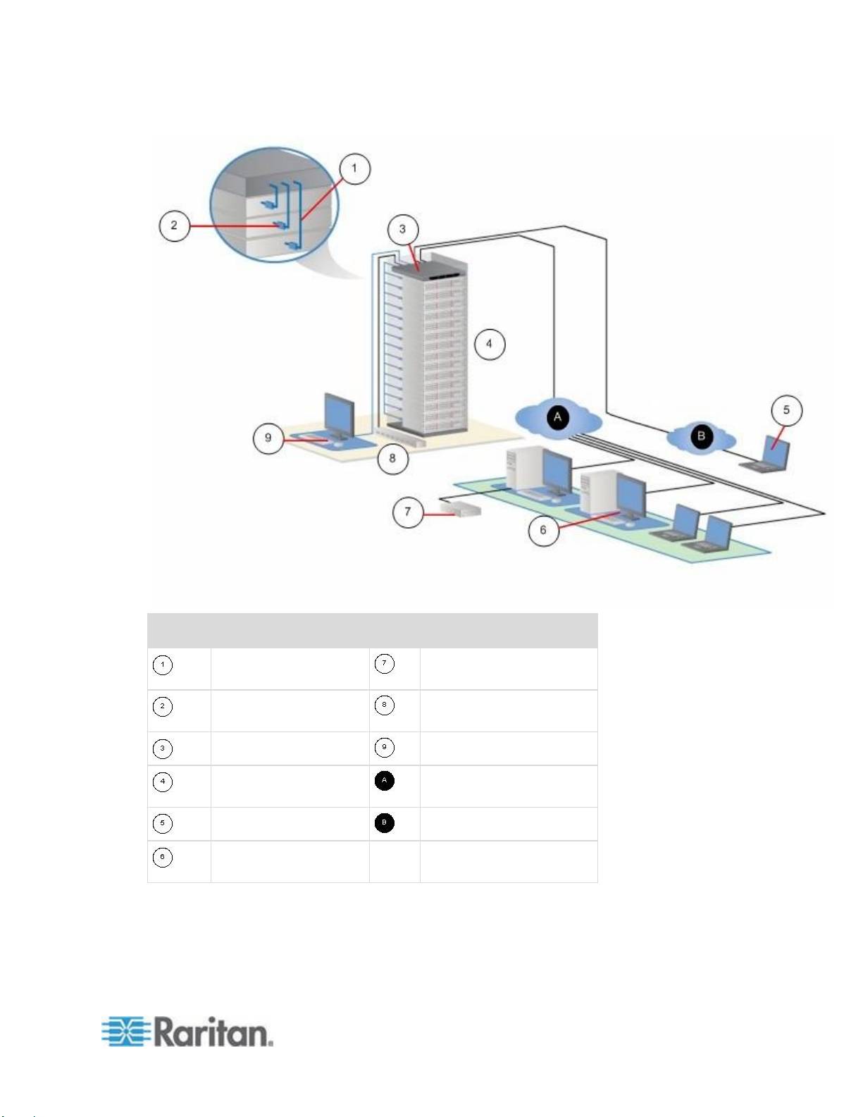
Diagram key
Cat5 cable
Remote virtual media USB
drive(s)
Computer Interface
Module (CIM)
Rack PDU (power strip)
KSX II
Local access
Remote KVM and serial
devices
IP LAN/WAN
Modem access
PSTN
Remote (network)
access
Page 14

Chapter 1: Introduction
4
KSX II Help
The KSX II help provides information on how to install, set up, and
configure the KSX II. It also includes information on accessing target
servers and power strips, using virtual media, managing users and
security, and maintaining and diagnosing the KSX II.
A PDF version of the help can be downloaded from the Raritan
Firmware and Documentation page
http://www.raritan.com/support/firmware-and-documentation/ on the
Raritan website. Raritan recommends that you refer to the Raritan
website for the most up-to-date user guides available.
To use online help, Active Content must be enabled in your browser. If
you are using Internet Explorer 7, you must enable Scriplets. Consult
your browser help for information on enabling these features.
Related Documentation
The KSX II help is accompanied by a KSX II Device Quick Setup Guide,
which can be found on the Raritan Firmware and Documentation page
http://www.raritan.com/support/firmware-and-documentation/ of
Raritan's website.
Installation requirements and instructions for client applications used with
the KSX II can be found in the KVM and Serial Access Clients Guide,
also found on the Raritan website. Where applicable, specific client
functions used with the KSX II are included in the help.
KSX II Client Applications
The following client applications can be used with the KSX II:
Virtual KVM Client (VKC)
Active KVM Client (AKC)
Multiplatform Client (MPC)
Raritan Serial Console (RSC)
See the KVM and Serial Client Guide for additional information on the
client applications. Also see the Working with Target Servers (on page
36) section of this guide, which contains information on using the clients
with the KSX II.
Note: MPC and VKC require the Java™ Runtime Environment (JRE™).
AKC is .NET based.
Page 15

Chapter 1: Introduction
5
Virtual Media
Product Features
All KSX II models support virtual media. The benefits of virtual media mounting of remote drives/media on the target server to support software
installation and diagnostics - are now available in all of the KSX II
models. Virtual media sessions can be secured by using 128-bit and
256-bit AES or RC4 encryption.
Each KSX II comes equipped with virtual media to enable remote
management tasks using the widest variety of CD, DVD, USB, internal
and remote drives, and images. Unlike other solutions, the KSX II
supports virtual media access of hard drives and remotely mounted
images for added flexibility and productivity.
The new D2CIM-VUSB and D2CIM-DVUSB CIMs (computer interface
module) support virtual media sessions to KVM target servers supporting
the USB 2.0 interface. This new CIM also supports Absolute Mouse
Synchronization as well as remote firmware updates.
Note: The black connector on the DVUSB CIM is used for keyboard and
mouse. The gray connector is used for virtual media. Keep both plugs of
the CIM connected to the device. The device may not operate properly if
both plugs are not connected to the target server.
Hardware
KVM and serial remote access over IP
1U rack-mountable; brackets included
DKSX2-144 - 4 serial/4 KVM server ports
DKSX2-188 - 8 serial/8 KVM server ports
1 KVM channel shareable by 8 users, multiple serial users.
UTP (Cat5/5e/6) server cabling
Dual Ethernet ports (10/100/1000 LAN) with failover
Field upgradeable
Local KVM port for in-rack access
One front and three back panel USB 2.0 ports for supported USB
devices
Fully concurrent with remote user access
Local Graphical User Interface (GUI) for administration
Both KVM and serial targets can be connected using KVM local
port
Page 16

Chapter 1: Introduction
6
Local serial port (RS232) for CLI-based administration and serial
target access
Integrated power control
Dual dedicated power control ports
LED indicators for network activity, and remote KVM user status
Hardware reset button
Internal modem
Centralized access security
Software
Virtual media with D2CIM-VUSB and D2CIM-DVUSB CIMs
Absolute Mouse Synchronization with D2CIM-VUSB CIM and
D2CIM-DVUSB CIMs
Plug-and-Play
Web-based access and management
Intuitive Graphical User Interface (GUI)
256-bit encryption of complete KVM signal, including video and
virtual media
LDAP/LDAPS, Active Directory®, RADIUS, or internal with local
authentication and authorization
DHCP or fixed IP addressing
Smart card/CAC authentication
SNMP and Syslog management
IPv4 and IPv6 support
Power control associated directly with servers to prevent mistakes
Integration with Raritan's CommandCenter Secure Gateway
(CC-SG) management unit
CC Unmanage feature to remove the device from CC-SG control
Page 17
Chapter 1: Introduction
7
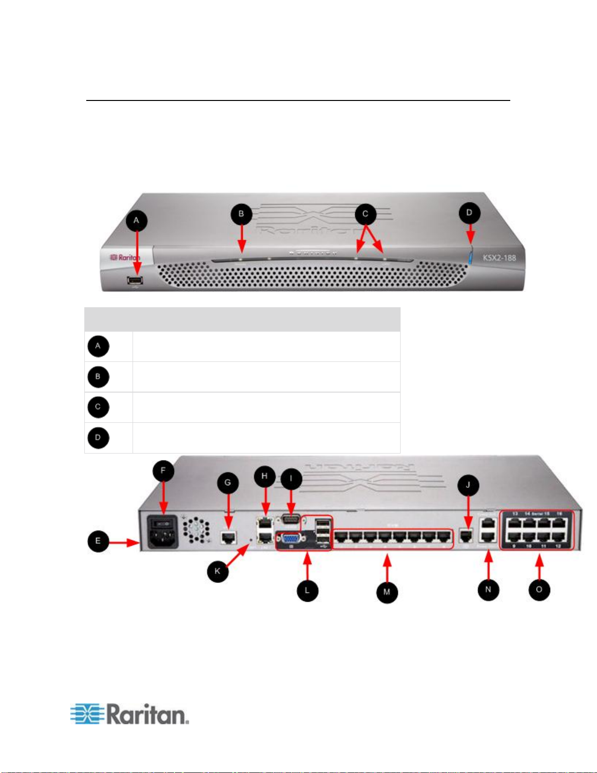
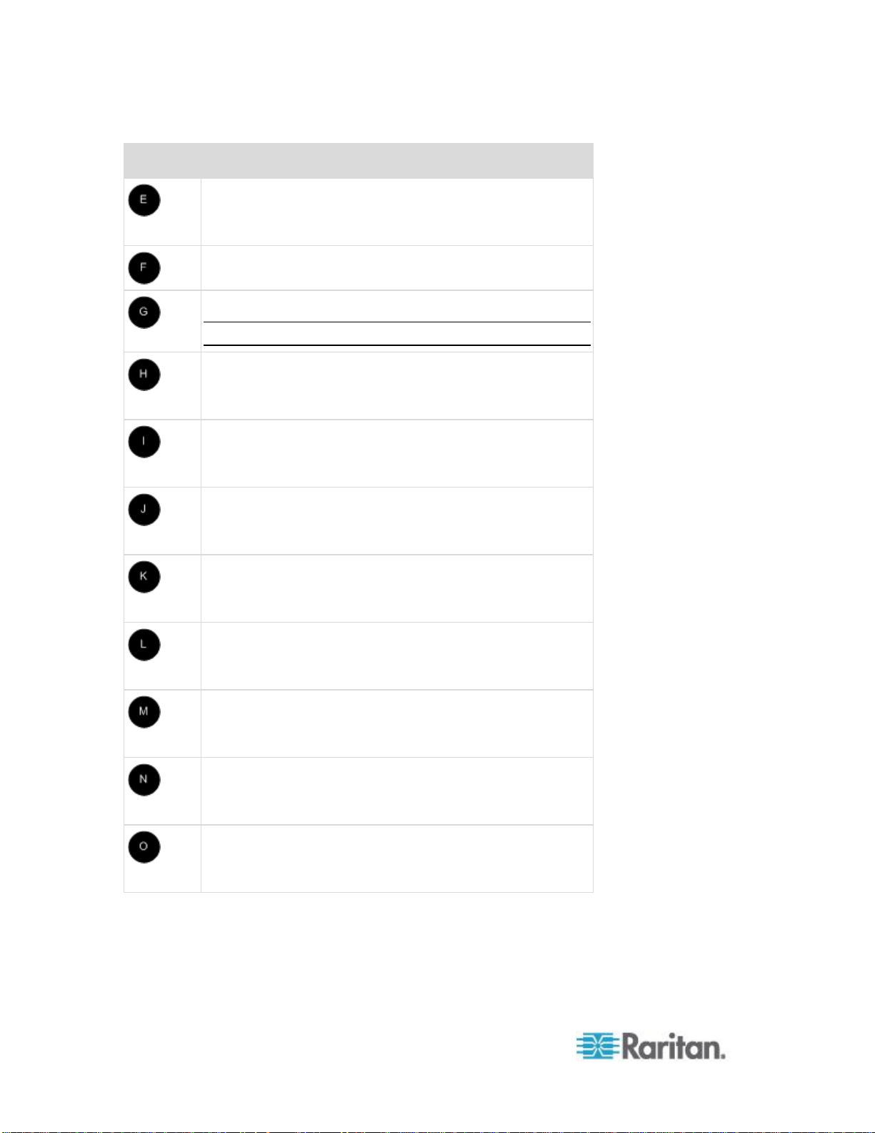
External Product Overview
Item
Description
USB port
Remote indicator light
LAN1 and LAN2 indicator lights
Power indicator light
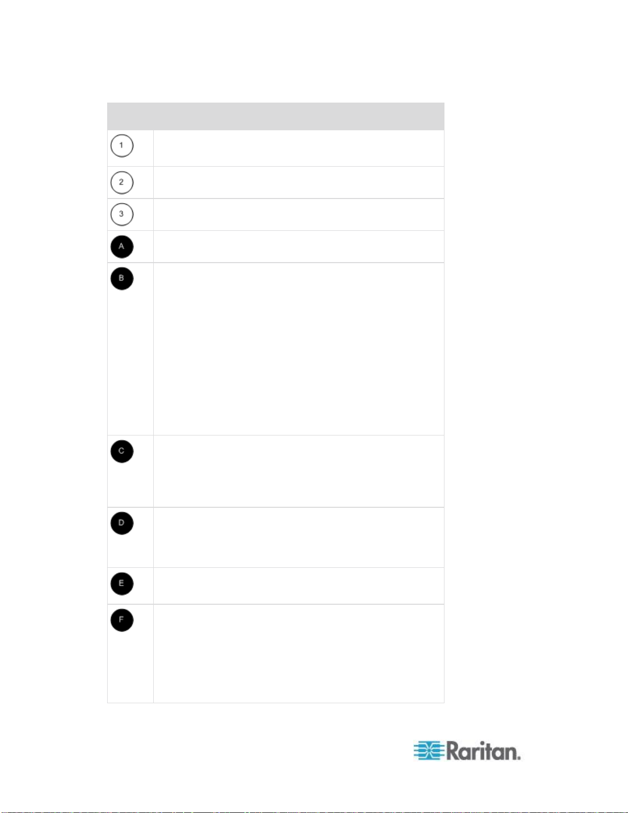
The following diagram indicates the external components of the KSX II.
Note that the KSX II 144 will have 4 KVM ports and 4 serial ports as
compared to the KSX II 188 used in the diagram, which has 8 KVM ports
and 8 serial ports.
Page 18
Chapter 1: Introduction
8
Item
Description
AC power cord plug
See Power Control (on page 158) for additional
information.
Power on/off switch
LAN 3 port
Note: The LAN 3 port is reserved for future use.
LAN1 and LAN2 ports
See Step 3: Connect the Equipment for additional
information.
Admin port
See Step 3: Connect the Equipment for additional
information.
External modem port
See Modem Configuration (on page 257) for additional
information.
Reset button
See Resetting the KSX II Using the Reset Button (on
page 256) for additional information.
Local port
See Step 3: Connect the Equipment for additional
information.
KVM ports
See Step 3: Connect the Equipment for additional
information.
Power Ctrl. 1 and Power Ctrl. 2
See Power Control (on page 158) for additional
information.
Serial ports
See Step 3: Connect the Equipment for additional
information.
Page 19
Chapter 1: Introduction
9
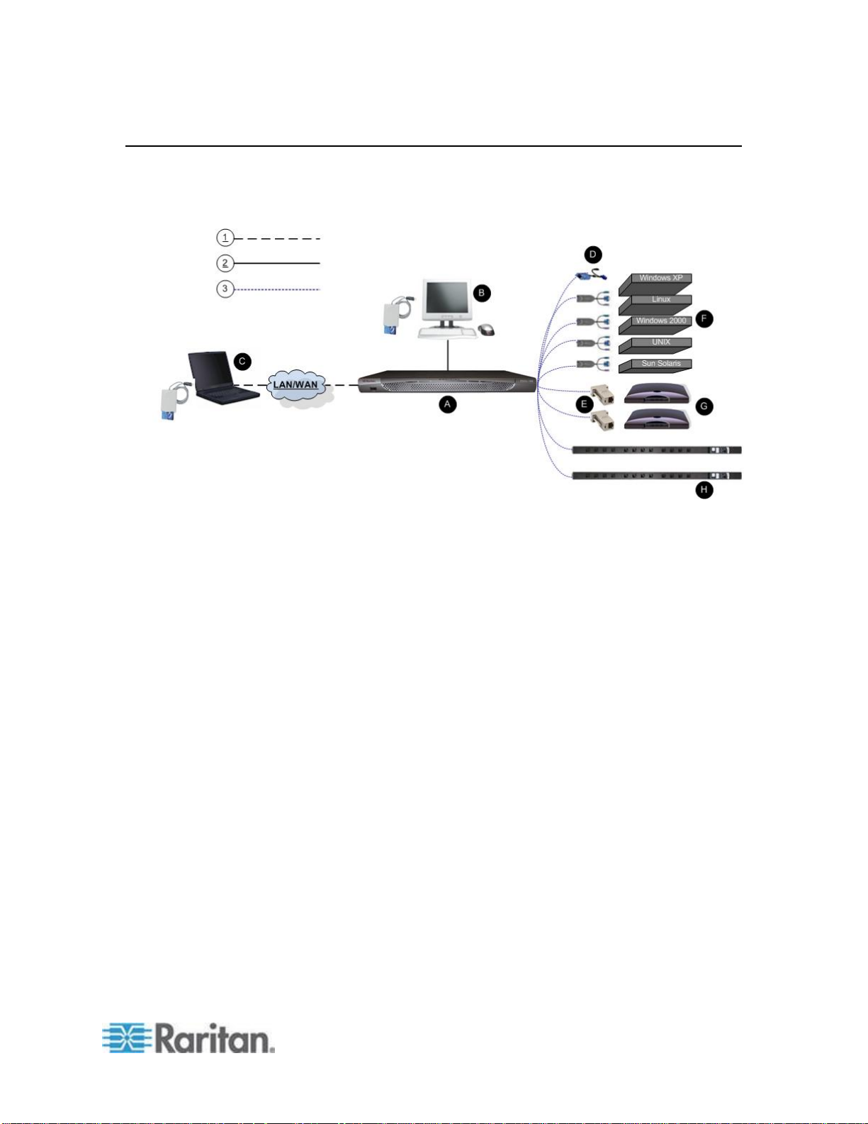
Terminology
This manual uses the following terminology for the components of a
typical KSX II configuration:
Page 20
Chapter 1: Introduction
10
Diagram key
TCP/IP
IPv4 and/or IPv6
KVM (Keyboard, Video, Mouse)
UTP Cable (Cat5/5e/6)
KSX II
Local Access Console
Local User - an optional user console (consisting of a
keyboard, mouse, and multi-sync VGA monitor) attached
directly to the KSX II to control KVM target servers and serial
targets locally (directly at the rack, not through the network). A
USB smart card reader can also be attached at the Local port
to mount onto a target server.
Local Administrator - use the Local Administrator port to
connect the KSX II directly to a workstation to manage your
serial targets and configure the system with a terminal
emulation program such as HyperTerminal. The Local
Administrator port requires the use of a standard null modem
cable.
Remote PC
Networked computers used to access and control KVM target
servers and serial targets connected to the KSX II. Refer to
Supported Operating Systems (Clients) for a list of the
Operating Systems supported by the KSX II remotely.
CIMs
Dongles that connect to each target server. Available for all of
the supported Operating Systems. Refer to Supported CIMs
for information about the CIMs supported by the KSX II.
Serial Adapter
Adapters that connect serial cables.
Target Servers
KVM Target Servers - servers with video cards and user
interfaces (for example, Windows®, Linux®, Solaris™, and so
forth) connected remotely via the KSX II. Refer to Supported
Operating Systems and CIMs (Target Servers) for a list of the
supported Operating Systems and CIMs.
Serial Targets - Servers, routers, and switches that have a
Page 21

Chapter 1: Introduction
11
Diagram key
serial port connected remotely via KSX II.
Routers
Dominion PX Rack PDU (Power Strip)
Raritan rack PDUs accessed remotely via the KSX II.
Package Contents
Amount
included
Item
1
Dominion KSX II device
1
Dominion KSX II Quick Setup Guide
1
Rackmount Kit
1
AC Power Cord
1
Cat5 Network Cable
1
Cat5 Network Crossover Cable
1
Set of 4 Rubber Feet (for desktop use)
1
Application Note
1
Warranty Card
1
Phone Line Cable
1
Loopback Adapter
Each KSX II ships as a fully-configured stand-alone product in a
standard 1U 19" rackmount chassis. Each KSX II device ships with the
following contents:
Page 22

12
In This Chapter
Overview .................................................................................................. 12
Default Login Information ........................................................................ 12
Getting Started ........................................................................................ 13
Default
Value
User name
The default user name is admin. This user has
administrative privileges.
Password
The default password is raritan.
Passwords are case sensitive and must be entered in the
exact case combination in which they were created. For
example, the default password raritan must be entered
entirely in lowercase letters.
The first time you start the KSX II, you are required to
change the default password.
IP address
The KSX II ships with the default IP address of
192.168.0.192.
Important: For backup and business continuity purposes, it is strongly
recommended that you create a backup administrator user name and
password and keep that information in a secure location.
Chapter 2
Installation and Configuration
Overview
This section provides a brief overview of the installation process. Each
step is further detailed in the remaining sections of this chapter.
To install and configure the KSX II:
Step 1: Configure KVM Target Servers (on page 13)
Step 2: Configure Network Firewall Settings (on page 22)
Step 3: Connect the Equipment (on page 22)
Step 4: Configure the KSX II (on page 28)
Step 5 (Optional): Configure Keyboard Language (on page 35)
You will need to know the default IP address, username, and password
for initial configuration. See Default Login Information (on page 12).
Default Login Information
Page 23

Chapter 2: Installation and Configuration
13
Getting Started
Step 1: Configure KVM Target Servers
KVM target servers are the computers that will be accessed and
controlled via the KSX II. Before installing the KSX II, configure all KVM
target servers to ensure optimum performance. This configuration
applies only to KVM target servers, not to the client workstations (remote
PCs) used to access the KSX II remotely. See Terminology for
additional information.
Desktop Background
For optimal bandwidth efficiency and video performance, KVM target
servers running graphical user interfaces such as Windows®, Linux®,
X-Windows, Solaris™, and KDE require configuration. The desktop
background need not be completely solid but desktop backgrounds
featuring photos or complex gradients might degrade performance.
Mouse Settings
The KSX II operates in several mouse modes:
Absolute Mouse Mode™ (D2CIM-VUSB only)
Intelligent Mouse Mode (do not use an animated mouse)
Standard Mouse Mode
Mouse parameters do not have to be altered for Absolute Mouse
Synchronization but D2CIM-VUSB or D2CIM-DVUSB is required for this
mode. For both the Standard and Intelligent mouse modes, mouse
parameters must be set to specific values, which are described here.
Mouse configurations will vary on different target operating systems.
Consult your OS documentation for additional detail.
Intelligent mouse mode generally works well on most Windows
platforms. Intelligent mouse mode may produce unpredictable results
when active desktop is set on the target. For additional information on
Intelligent mouse mode settings, see Intelligent Mouse Mode (on page
71).
Servers with internal KVM switches inside the blade chassis typically do
not support absolute mouse technology.
Page 24

Chapter 2: Installation and Configuration
14
Operating System Mouse and Video Settings
This section provides video mode and mouse information specific to the
operating system in use on the target server.
Windows XP, Windows 2003 and Windows 2008 Settings
To configure KVM target servers running Windows XP®,
Windows 2003® and Windows 2008®:
1. Configure the mouse settings:
a. Choose Start > Control Panel > Mouse.
b. Click the Pointer Options tab.
c. In the Motion group:
Set the mouse motion speed setting to exactly the middle
speed.
Disable the "Enhance pointer precision" option.
Disable the Snap To option.
Click OK.
2. Disable transition effects:
a. Select the Display option from the Control Panel.
b. Click the Appearance tab.
Click the Effects button.
Deselect the "Use the following transition effect for menus
and tooltips" option.
3. Click OK and close the Control Panel.
Note: For KVM target servers running Windows XP, Windows 2000 or
Windows 2008, you may wish to create a user name that will be used
only for remote connections through the KSX II. This will enable you to
keep the target server's slow mouse pointer motion/acceleration settings
exclusive to the KSX II connection.
Windows XP, 2000, and 2008 login pages revert to preset mouse
parameters that differ from those suggested for optimal KSX II
performance. As a result, mouse synchronization may not be optimal for
these screens.
WARNING! Proceed only if you are comfortable adjusting the registry on
Windows KVM target servers. You can obtain better KSX II mouse
synchronization at the login pages by using the Windows registry editor
to change the following settings: HKey_USERS\.DEFAULT\Control
Panel\Mouse: > MouseSpeed = 0;MouseThreshold
1=0;MouseThreshold 2=0.
Page 25

Chapter 2: Installation and Configuration
15
Windows Vista Settings
To configure KVM target servers running Windows Vista®
operating system:
1. Configure the mouse settings:
a. Choose Start > Settings > Control Panel > Mouse.
b. Select "Advanced system settings" from the left navigation panel.
The System Properties dialog opens.
c. Click the Pointer Options tab.
d. In the Motion group:
Set the mouse motion speed setting to exactly the middle
speed.
Disable the "Enhanced pointer precision" option.
Click OK.
2. Disable animation and fade effects:
a. Select the System option from the Control Panel.
b. Select Performance Information then Tools > Advanced Tools >
Adjust to adjust the appearance and performance of Windows.
c. Click the Advanced tab.
d. Click the Settings button in the Performance group to open the
Performance Options dialog.
e. Under Custom options, deselect the following checkboxes:
Animation options:
Animate controls and elements inside windows
Animate windows when minimizing and maximizing
Fade options:
Fade or slide menus into view
Fade or slide ToolTips into view
Fade out menu items after clicking
3. Click OK and Close the Control Panel.
To configure KVM target servers running Windows 7® operating
system:
1. Configure the mouse settings:
a. Choose Start > Control Panel > Hardware and Sound > Mouse.
b. Click the Pointer Options tab.
c. In the Motion group:
Page 26

Chapter 2: Installation and Configuration
16
Set the mouse motion speed setting to exactly the middle
speed.
Disable the "Enhanced pointer precision" option.
Click OK.
2. Disable animation and fade effects:
a. Select Control Panel > System and Security.
b. Select System and then select "Advanced system settings" from
the left navigation panel. The System Properties dialog appears.
c. Click the Advanced tab.
d. Click the Settings button in the Performance group to open the
Performance Options dialog.
e. Under Custom options, deselect the following checkboxes:
Animation options:
Animate controls and elements inside windows
Animate windows when minimizing and maximizing
Fade options:
Fade or slide menus into view
Fade or slide ToolTips into view
Fade out menu items after clicking
3. Click OK and Close the Control Panel.
Windows 2000 Settings
To configure KVM target servers running Microsoft Windows
2000® operating system:
1. Configure the mouse settings:
a. Choose Start > Control Panel > Mouse.
b. Click the Motion tab.
Set the acceleration to None.
Set the mouse motion speed setting to exactly the middle
speed.
Click OK.
2. Disable transition effects:
a. Select the Display option from the Control Panel.
b. Click the Effects tab.
Page 27

Chapter 2: Installation and Configuration
17
Deselect the "Use the following transition effect for menus
and tooltips" option.
3. Click OK and close the Control Panel.
Linux Settings (Red Hat 4)
Note: The following settings are optimized for Standard Mouse mode
only.
To configure KVM target servers running Linux® (graphical user
interface):
1. Configure the mouse settings:
a. Red Hat 5 users, choose Main Menu > Preferences > Mouse.
Red Hat 4 users, choose System > Preferences > Mouse. The
Mouse Preferences dialog appears.
b. Click on the Motion tab.
c. Within the Speed group, set the Acceleration slider to the exact
center.
d. Within the Speed group, set the Sensitivity towards low.
e. Within the Drag & Drop group, set the Threshold towards small.
f. Close the Mouse Preferences dialog.
Note: If these steps do not work, issue the xset mouse 1 1 command
as described in the Linux command line instructions.
2. Configure the screen resolution:
a. Choose Main Menu > System Settings > Display. The Display
Settings dialog appears.
b. On the Settings tab, select a Resolution supported by the KSX II.
c. Click OK.
Note: Once connected to the target server, in many Linux graphical
environments, the <Ctrl> <Alt> <+> command will change the video
resolution, scrolling through all available resolutions that remain enabled
in the XF86Config or /etc/X11/xorg.conf, depending on your X server
distribution
Note: If you change the video resolution, you must log out of the target
server and log back in for the video settings to take effect.
Page 28

Chapter 2: Installation and Configuration
18
SUSE Linux 10.1 Settings
Note: Do not attempt to synchronize the mouse at the SUSE Linux® login
prompt. You must be connected to the target server to synchronize the
mouse cursors.
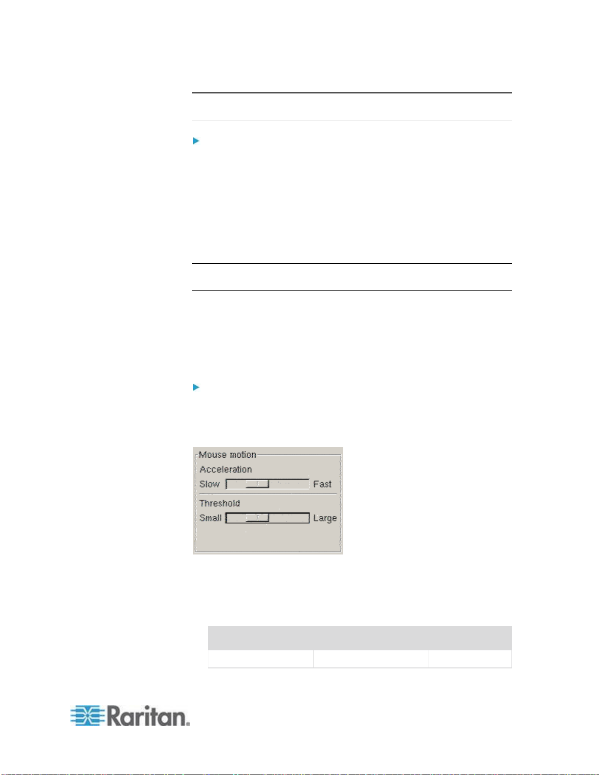
To configure the mouse settings:
1. Choose Desktop > Control Center. The Desktop Preferences dialog
appears.
2. Click Mouse. The Mouse Preferences dialog appears.
3. Open the Motion tab.
4. Within the Speed group, set the Acceleration slider to the exact
center position.
5. Within the Speed group, set the Sensitivity slider to low.
6. Within the Drag & Drop group, set the Threshold slider to small.
7. Click Close.
To configure the video:
1. Choose Desktop Preferences > Graphics Card and Monitor. The
Card and Monitor Properties dialog appears.
2. Verify that a Resolution and Refresh Rate is in use that is supported
by the KSX II. See Supported Video Resolutions (on page 280) for
more information.
Note: If you change the video resolution, you must log out of the
target server and log back in for the video settings to take effect.
Make Linux Settings Permanent
Note: These steps may vary slightly depending on the specific version of
Linux® in use.
To make your settings permanent in Linux (prompt):
1. Choose System Menu > Preferences > Personal > Sessions.
2. Click the Session Options tab.
3. Select the "Prompt on log off" checkbox and click OK. This option
prompts you to save your current session when you log out.
4. Upon logging out, select the "Save current setup" option from the
dialog.
5. Click OK.
Page 29
Chapter 2: Installation and Configuration
19
Tip: If you do not want to be prompted upon log out, follow these
Display resolution
Vertical refresh rate
Aspect ratio
1600 x 1200
60 Hz
4:3
procedures instead.
To make your settings permanent in Linux (no prompt):
1. Choose Desktop > Control Center > System > Sessions.
2. Click the Session Options tab.
3. Deselect the "Prompt on the log off" checkbox.
4. Select the "Automatically save changes to the session" checkbox
and click OK. This option automatically saves your current session
when you log out.
Make UNIX Settings Permanent
Note: These steps may vary slightly depending on the type of UNIX® (for
example, Solaris™, IBM® AIX™) and the specific version in use.
1. Choose Style Manager > Startup. The Style Manager - Startup
dialog appears.
2. On the Logout Confirmation dialog, select the On option. This option
prompts you to save your current session when you log out.
Sun Solaris Settings
To configure KVM target servers running Sun™ Solaris™:
1. Set the mouse acceleration value to exactly 1 and the threshold to
exactly 1. This can be performed from:
The graphical user interface.
The command line xset mouse a t where a is the acceleration
and t is the threshold.
2. All KVM target servers must be configured to one of the display
resolutions supported by the KSX II. The most popular supported
resolutions for Sun machines are:
Page 30
Chapter 2: Installation and Configuration
20
Display resolution
Vertical refresh rate
Aspect ratio
1280 x 1024
60,75,85 Hz
5:4
1152 x 864
75 Hz
4:3
1024 x 768
60,70,75,85 Hz
4:3
800 x 600
56,60,72,75,85 Hz
4:3
720 x 400
85 Hz
9:5
640 x 480
60,72,75,85 Hz
4:3
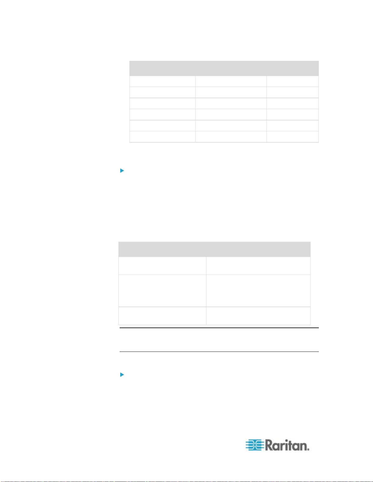
3. KVM target servers running the Solaris operating system must output
If you have:
Use this video output adapter:
Sun 13W3 with composite
sync output
APSSUN II Guardian converter
Sun HD15 with composite
sync output
1396C converter to convert from
HD15 to 13W3 and an APSSUN II
Guardian converter to support
composite sync
Sun HD15 with separate sync
output
APKMSUN Guardian converter
VGA video (H-and-V sync, not composite sync).
To change your Sun video card output from composite sync to
the nondefault VGA output:
1. Issue the Stop+A command to drop to bootprom mode.
2. Issue the following command to change the output resolution: setenv
output-device screen:r1024x768x70
3. Issue the boot command to reboot the server.
You can also contact your Raritan representative to purchase a video
output adapter:
Note: Some of the standard Sun background screens may not center
precisely on certain Sun servers with dark borders. Use another
background or place a light colored icon in the upper left hand corner.
Mouse Settings
To configure the mouse settings (Sun Solaris 10.1):
1. Choose Launcher. Application Manager - Desktop Controls opens.
2. Choose Mouse Style Manager. The Style Manager - Mouse dialog
appears.
3. Set the Acceleration slider to 1.0.
Page 31

Chapter 2: Installation and Configuration
21
4. Set the Threshold slider to 1.0.
Card
To check resolution:
To change resolution:
32-bit
# /usr/sbin/pgxconfig -prconf
1. # /usr/sbin/pgxconfig -res
1024x768x75
2. Log out or restart computer.
64-bit
# /usr/sbin/m64config -prconf
1. # /usr/sbin/m64config -res
1024x768x75
2. Log out or restart computer.
32-bit
and
64-bit
# /usr/sbin/fbconfig -prconf
1. # /usr/sbin/fbconfig -res
1024x768x75
2. Log out or restart computer.
5. Click OK.
Accessing the Command Line
1. Right click.
2. Choose Tools > Terminal. A terminal window opens. (It is best to be
at the root to issue commands.)
Video Settings (POST)
Sun systems have two different resolution settings: a POST resolution
and a GUI resolution. Run these commands from the command line.
Note: 1024x768x75 is used as an example here; substitute the resolution
and refresh rate you are using.
To check current POST resolution:
Run the following command as the root: # eeprom output-device
To change POST resolution:
1. Run # eeprom output-device=screen:r1024x768x75.
2. Log out or restart computer.
Video Settings (GUI)
The GUI resolution can be checked and set using different commands
depending on the video card in use. Run these commands from the
command line.
Note: 1024x768x75 is used as an example here; substitute the resolution
and refresh rate you are using.
Page 32

Chapter 2: Installation and Configuration
22
IBM AIX 5.3 Settings
Follow these steps to configure KVM target servers running IBM® AIX™
5.3.
To configure the mouse:
1. Go to Launcher.
2. Choose Style Manager.
3. Click Mouse. The Style Manager - Mouse dialog appears.
4. Use the sliders to set the Mouse acceleration to 1.0 and Threshold to
1.0.
5. Click OK.
To configure the video:
1. From the Launcher, select Application Manager.
2. Select System_Admin.
3. Choose Smit > Devices > Graphic Displays > Select the Display
Resolution and Refresh Rate.
4. Select the video card in use.
5. Click List. A list of display modes is presented.
6. Select a resolution and refresh rate supported by the KSX II. See
Supported Video Resolutions (on page 280) for more information.
Note: If you change the video resolution, you must log out of the target
server and log back in for the video settings to take effect.
Apple Macintosh Settings
For KVM target servers running an Apple Macintosh® operating system,
the preferred method is to use the D2CIM-VUSB and Absolute Mouse
Synchronization.
Note: 'USB Profile 'Mac OS-X, version 10.4.9 and later' must be selected
from the USB Profile menu or the Port Configuration page.
Step 2: Configure Network Firewall Settings
To access KSX II through a network firewall via Multi-Platform Client or
through the Port Access page, your firewall must allow communication
on TCP Port 5000 or another port that you designate.
Page 33

Chapter 2: Installation and Configuration
23
To take advantage of the KSX II:
The firewall must allow
inbound communication on:
Web-access capabilities
Port 443 - standard TCP port for
HTTPS communication
Automatic redirection of HTTP
requests to HTTPS
(so the more common
“http://xxx.xxx.xxx.xxx” can be
used instead of
“https://xxx.xxx.xxx.xxx”)
Port 80 - standard TCP port for
HTTP communication
See Network Settings (on page 136) for additional information about
designating another discovery port.
Step 3: Connect the Equipment
Connect the KSX II to the power supply, network, local PC, local video
display, keyboard and mouse, KVM target servers, and serial targets.
A. AC Power
To connect the power supply:
1. Attach the included AC power cord to the KSX II and plug into an AC
power outlet.
Page 34

Chapter 2: Installation and Configuration
24
B. Network Port
Connection
Description
Monitor
Attach a standard multi-sync VGA monitor to the
HD15 (female) video port.
Keyboard
Attach a standard USB keyboard to one of the USB
Type A (female) ports.
Mouse
Attach a standard USB mouse to one of the USB
Type A (female) ports.
The KSX II provides two Ethernet ports for failover purposes (not for
load-balancing). By default, only LAN1 is active and the automatic
failover is disabled. When enabled, if the KSX II internal network
interface or the network switch to which it is connected becomes
unavailable, LAN2 will be enabled using the same IP address.
Note: Because a failover port is not activated until after a failover has
actually occurred, Raritan recommends that you either not monitor the
failover port or monitor it only after a failover occurs.
To connect the network:
1. Connect a standard Ethernet cable (included) from the network port
labeled LAN1 to an Ethernet switch, hub, or router.
2. To make use of the optional KSX II Ethernet failover capabilities:
Connect a standard Ethernet cable from the network port labeled
LAN2 to an Ethernet switch, hub, or router.
Enable Automatic Failover on the Network Configuration page.
Note: Use both network ports only if you want to use one as a failover
port.
C. Local User Port (Local Video, Display and Keyboard) and Local Admin
Port
For convenient access to KVM target servers and serial devices while at
the rack, use the KSX II Local Access port. While the local port is
required for installation and setup, it is optional for subsequent use. The
local port provides the KSX II Local Console graphical user interface for
administration and target server access.
To connect the Local User port:
Attach a multi-sync VGA monitor, keyboard, and mouse to the
respective Local User ports using a USB keyboard and mouse.
Page 35

Chapter 2: Installation and Configuration
25
You can use the Local Admin port to connect the KSX II directly to a
workstation to manage your serial targets and configure the system with
a terminal emulation program such as HyperTerminal. The Local Admin
port requires the use of a standard null modem cable.
Note: When Local Authorization and Authentication is set to None,
logging in to serial admin console requires username input.
D. KVM Target Server Ports
The KSX II uses standard UTP cabling (Cat5/5e/6) to connect to each
target server. Refer to Specifications (on page 270) for additional
information.
To connect a KVM target server to the KSX II:
1. Use the appropriate Computer Interface Module (CIM). Refer to
Supported Operating Systems and CIMs (KVM Target Servers)
(on page 272) for more information about the CIMs to use with each
operating system.
2. Attach the HD15 video connector of your CIM to the video port of
your KVM target server. Ensure that your target server's video has
already been configured to a supported resolution and refresh rate.
For Sun servers, also ensure that your target server's video card has
been set to output standard VGA (H-and-V sync) and not composite
sync.
3. Attach the keyboard/mouse connector of your CIM to the
corresponding ports on your target server. Using a standard
straight-through UTP (Cat5/5e/6) cable, connect the CIM to an
available server port on the back of your KSX II device.
Note: The DCIM-USB G2 provides a small slide switch on the back of the
CIM. Move the switch to P for PC-based USB target servers. Move the
switch to S for Sun USB target servers.
A new switch position takes effect only after the CIM is power-cycled. To
power-cycle the CIM, remove the USB connector from the target server
and plug it back in a few seconds later.
E. Rack PDU (Power Strip)
To connect the Dominion PX to the KSX II:
1. Plug one end of a Cat5 cable into the Serial port on the front of the
Dominion PX.
2. Connect the other end of the Cat5 cable to either the Power Ctrl. 1 or
Power Ctrl. 2 ports on the back of the KSX II.
3. Attach an AC power cord to the target server and an available rack
PDU outlet.
Page 36

Chapter 2: Installation and Configuration
26
4. Connect the rack PDU to an AC power source.
Diagram key
KSX II
PX serial port
KSX II Power
Ctrl. 1 Port or
Power Ctrl. 2
Port
Cat5 cable
PX
5. Power on the KSX II device.
Important: When using CC-SG, the power ports should be inactive
before attaching rack PDUs that were swapped between the power
ports. If this is not done, there is a possibility that the number of
power outlets will not be correctly detected, especially after
swapping 8 and 20 outlet rack PDU models.
Page 37

Chapter 2: Installation and Configuration
27
F. Serial Target Ports
Vendor
Device
Console
connector
Serial
connection
Checkpoint
Firewall
DB9M
ASCSDB9F
adapter and a
CAT 5 cable
Cisco
PIX Firewall
Cisco
Catalyst
RJ-45
CRLVR-15
rollover cable; or
CRLVR-1
adapter cable
and a CAT5
cable
CRLVR-1 cable
for connecting a
terminal port
(RJ-45 Connector
type) of KSX II-48
models that have
this connector to
another KSX II.
Cisco
Router
DB25F
ASCSDB25M
adapter and a
CAT 5 cable
Hewlett
Packard®
UNIX® Server
DB9M
ASCSDB9F
adapter and a
CAT 5 cable
Silicon
Graphics
Origin
Sun™
SPARCStation
DB25F
ASCSDB25M
adapter and a
CAT 5 cable
Sun
Netra T1
RJ-45
CRLVR-15 cable;
or CRLVR-1
adapter and a
CAT5 cable
Sun
Cobalt
DB9M
ASCSDB9F
adapter and a
CAT 5 cable
Various
Windows NT®
To connect a serial target to the KSX II, use a Cat5 cable with an
appropriate serial adapter.
The following table lists the necessary KSX II hardware (adapters and/or
cables) for connecting the KSX II to common vendor/model
combinations.
Page 38

Chapter 2: Installation and Configuration
28
Go to the Support page on Raritan's website (www.raritan.com) to obtain
a list of commonly used cables and adapters.
Step 4: Configure the KSX II
The first time you power up the KSX II device, there is some initial
configuration that you need to perform through the KSX II Local Console:
Change the default password.
Assign the IP address.
Name the KVM target servers.
Changing the Default Password
The KSX II ships with a default password. The first time you start the
KSX II you are required to change that password.
To change the default password:
1. Power on the KSX II using the power switch(s) at the back of the
unit. Wait for the KSX II unit to boot. (A beep signals that the boot is
complete.)
2. Once the unit has booted, the KSX II Local Console is visible on the
monitor attached to the KSX II local port. Type the default username
(admin) and password (raritan) and click Login. The Change
Password screen is displayed.
3. Type your old password (raritan) in the Old Password field.
4. Type a new password in the New Password field and retype the new
password in the Confirm New Password field. Passwords can be up
to 64 characters in length and can consist of English, alphanumeric
characters as well as special characters.
5. Click Apply.
6. You will receive confirmation that the password was successfully
changed. Click OK. The Port Access page is displayed.
Note: The default password can also be changed from the Raritan
Multi-Platform Client (MPC). For more information, refer to Changing a
Password.
Page 39

Chapter 2: Installation and Configuration
29
Assigning an IP Address
These procedures describe how to assign an IP address on the Network
Settings page. For complete information about all of the fields and the
operation of this page, see Network Settings.
To assign an IP address:
1. Choose Device Settings > Network. The Network Settings page
opens.
2. Specify a meaningful Device Name for your KSX II device. Up to 32
alphanumeric characters using valid special characters and no
spaces.
3. In the IPv4 section, enter or select the appropriate IPv4-specific
network settings:
a. Enter the IP Address if needed. The default IP address is
192.168.0.192.
b. Enter the Subnet Mask. The default subnet mask is
255.255.255.0.
c. Enter the Default Gateway if None is selected from the IP Auto
Configuration drop-down.
d. Enter the Preferred DHCP Host Name if DHCP is selected from
the IP Auto Configuration drop-down.
e. Select the IP Auto Configuration. The following options are
available:
None (Static IP) - This option requires that you manually specify
the network parameters.
This is the recommended option because the KSX II is an
infrastructure device and its IP address should not change.
DHCP - Dynamic Host Configuration Protocol is used by
networked computers (clients) to obtain unique IP addresses
and other parameters from a DHCP server.
With this option, network parameters are assigned by the DHCP
server. If DHCP is used, enter the Preferred host name (DHCP
only). Up to 63 characters.
4. If IPv6 is to be used, enter or select the appropriate IPv6-specific
network settings in the IPv6 section:
a. Select the IPv6 checkbox to activate the fields in the section.
b. Enter a Global/Unique IP Address. This is the IP address
assigned to the KSX II.
c. Enter the Prefix Length. This is the number of bits used in the
IPv6 address.
d. Enter the Gateway IP Address.
Page 40

Chapter 2: Installation and Configuration
30
e. Link-Local IP Address. This address is automatically assigned to
the device. It is used for neighbor discovery or when no routers
are present. Read-Only
f. Zone ID. This identifies the device with which the address is
associated. Read-Only
g. Select the IP Auto Configuration. The following options are
available:
None - Use this option if you do not want an auto IP configuration
and prefer to set the IP address yourself (static IP). This is the
default and recommended option.
If None is selected for the IP auto configuration, the following
Network Basic Settings fields are enabled: Global/Unique IP
Address, Prefix Length, and Gateway IP Address allowing you to
manually set the IP configuration.
Router Discovery - Use this option to automatically assign IPv6
addresses that have Global or Unique Local significance beyond
that of the Link Local, which only applies to a directly connected
subnet.
5. Select Obtain DNS Server Address Automatically if DHCP is
selected and Obtain DNS Server Address is enabled. When Obtain
DNS Server Address Automatically, the DNS information provided by
the DHCP server will be used.
6. If Use the Following DNS Server Addresses is selected, regardless
of whether DHCP is selected or not, the addresses entered in this
section will be used to connect to the DNS server.
Enter the following information if the Following DNS Server
Addresses option is selected. These addresses are the primary and
secondary DNS addresses that will be used if the primary DNS
server connection is lost due to an outage.
a. Primary DNS Server IP Address
b. Secondary DNS Server IP Address
7. When finished, click OK.
See LAN Interface Settings (on page 139) for information in configuring
this section of the Network Settings page.
Note: In some environments, the default LAN Interface Speed & Duplex
setting Autodetect (autonegotiator) does not properly set the network
parameters, which results in network issues. In these instances, setting
the KSX II LAN Interface Speed & Duplex field to 100 Mbps/Full Duplex
(or whatever option is appropriate to your network) addresses the issue.
See the Network Settings (on page 136) page for more information.
Page 41

Chapter 2: Installation and Configuration
31
Naming Target Servers
Character
Description
Character
Description
!
Exclamation point
;
Semi-colon
"
Double quote
=
Equal sign
#
Pound sign
>
Greater than sign
$
Dollar sign
?
Question mark
%
Percent sign
@
At sign
&
Ampersand
[
Left bracket
(
Left parenthesis
\
Backward slash
)
Right parenthesis
]
Right bracket
*
Asterisk
^
Caret
+
Plus sign
_
Underscore
,
Comma
`
Grave accent
-
Dash
{
Left brace
.
Period
|
Pipe sign
/
Forward slash
}
Right brace
<
Less than sign
~
Tilde
:
Colon
To name the target servers:
1. Connect all of the target servers if you have not already done so.
See Step 3: Connect the Equipment for a description of connecting
the equipment.
2. Using the KSX II Local Console, choose Device Settings > Port
Configuration. The Port Configuration page opens.
3. Click the Port Name of the target server you want to rename. The
Port Page opens.
4. Assign a name to identify the server connected to that port. The
name can be up to 32 characters, and alphanumeric and special
characters are allowed.
5. Click OK.
Valid Special Characters for Target Names
Page 42

Chapter 2: Installation and Configuration
32
Configuring Direct Port Access via Telnet, IP Address or SSH
The information in this topic is specific to enabling direct port access for
serial targets. Use the Enable Direct Port Access via URL option on the
Device Services page to enable direct port access for a KVM/serial port
connect to the KSX II. See Enabling Direct Port Access via URL (on
page 143).
To configure direct port access:
1. Choose Device Settings > Device Services. The Device Service
Settings page opens.
2. Type the IP address and ports used for SSH and Telnet in the
appropriate fields for each serial target.
Note that leaving all three fields blank will disable direct port access
for the serial target. To enable direct port access, you must do one of
the following:
Enable global Telnet or SSH access.
Input a valid IP address or TCP port in at least one of the three
fields.
Important: It is not recommended that more than one of these fields
is populated.
Below are examples of Telnet and IP:
Direct Port access via IP alias address:
Configure the IP alias address 192.168.1.59 for a serial target.
Once this is done, connection to the target through Telnet can be
done using "telnet 192.168.1.59".
Direct Port access via Telnet port:
Configure the Telnet TCP Port as "7770". Once this is done,
connection to the target can be done using "telnet <KSX II device
IP address> 7770".
Direct Port Access via SSH Port:
Configure the SSH TCP port as "7888". Once this is done,
connection to the target can be done by using “ssh –l <login>
<KSX II device IP address> -p 7888”.
Page 43

Chapter 2: Installation and Configuration
33
3. Click OK to save this information.
Once you have created the direct port access, it can be connected in a
client application such as PuTTY. Following is an example of how the
direct port access information would appear in PuTTY. Note that PuTTY
is not the only client application that can be used. It is used here for
sample purposes only.
Page 44

Chapter 2: Installation and Configuration
34
Note to CC-SG Users
Note to CC-SG Users
If you are using the KSX II in a CC-SG configuration, perform the
installation steps, and when finished, consult the CommandCenter
Secure Gateway User Guide, Administrator Guide, or Deployment
Guide to proceed (all found on Raritan's website, www.raritan.com,
under Support).
Note: The remainder of this help applies primarily to deploying the KSX II
device(s) without the integration functionality of CC-SG.
Remote Authentication
Note to CC-SG Users
When the KSX II is controlled by CommandCenter Secure Gateway,
CC-SG authenticates users and groups, except for local users requiring
Local port access. When CC-SG is controlling the KSX II, Local port
users will be authenticated against the local user database or the remote
authentication server (LDAP/LDAPS or RADIUS) configured on the KSX
II. They will not be authenticated against the CC-SG user database.
For additional information about CC-SG authentication, see the
CommandCenter Secure Gateway User Guide, Administrator Guide, or
Deployment Guide, which can be downloaded from the Support section
of the Raritan website http://www.raritan.com.
Supported Protocols
To simplify management of usernames and passwords, the KSX II
provides the ability to forward authentication requests to an external
authentication server. Two external authentication protocols are
supported: LDAP/LDAPS and RADIUS.
Note on Microsoft Active Directory
Microsoft® Active Directory® uses the LDAP/LDAPS protocol natively, and
can function as an LDAP/LDAPS server and authentication source for
the KSX II. If it has the IAS (Internet Authorization Server) component, a
Microsoft Active Directory server can also serve as a RADIUS
authentication source.
Page 45

Chapter 2: Installation and Configuration
35
Create User Groups and Users
As part of the initial configuration, you must define user groups and users
in order for users to access the KSX II.
The KSX II uses system-supplied default user groups and allows you to
create groups and specify the appropriate permissions to suit your
needs.
User names and passwords are required to gain access to the KSX II.
This information is used to authenticate users attempting to access your
KSX II. See User Management for details on adding and editing user
groups and users.
Step 5 (Optional): Configure Keyboard Language
Note: This step is not required if you are using the US/International
language keyboard.
If you are using a non-US language, the keyboard has to be configured
for the appropriate language. In addition, the keyboard language for the
client machine and the KVM target servers has to match.
Consult the documentation for your operating system for additional
information about changing the keyboard layout.
Changing the Keyboard Layout Code (Sun Targets)
Use this procedure if you are using a DCIM-SUSB and would like the
keyboard layout changed to another language.
To change the keyboard layout code (DCIM-SUSB only):
1. Open a Text Editor window on the Sun™ workstation.
2. Check that the Num Lock key is active and press the left Ctrl key and
the Del key on your keyboard. The Caps Lock light starts to blink,
indicating that the CIM is in Layout Code Change mode. The text
window displays: Raritan Computer, Inc. Current keyboard
layout code = 22h (US5 UNIX).
3. Type the layout code desired (for example, 31 for the Japanese
keyboard).
4. Press Enter.
5. Shut down the device and power on once again. The DCIM-SUSB
performs a reset (power cycle).
6. Verify that the characters are correct.
Page 46

36
In This Chapter
Interfaces ................................................................................................. 36
Proxy Server Configuration for use with MPC, VKC and AKC ................ 50
Virtual KVM Client (VKC) ......................................................................... 51
Active KVM Client (AKC) ......................................................................... 80
Multi-Platform Client (MPC) ..................................................................... 82
Raritan Serial Console (RSC).................................................................. 83
Interfaces
User interface
Local
Remote
Access
Admin
Access
Admin
KSX II Local Console
KSX II Remote Console
Virtual KVM Client (VKC)
Active KVM Client (AKC)
Multi-Platform Client
(MPC)
Raritan Serial Console
(RSC)
Command Line Interface
(CLI)
Chapter 3
Working with Target Servers
There are several interfaces in the KSX II providing you with easy access
any time, anywhere. The following table identifies these interfaces and
their use of target server access and administration locally and remotely:
Page 47

Chapter 3: Working with Target Servers
37
The following sections of the user guide contain information about using
specific interfaces to connect to the KSX II and manage targets:
KSX II Local Console Interface: KSX II Devices (see "KSX II
Local Console: KSX II Devices" on page 37)
KSX II Remote Console Interface (on page 38)
Virtual KVM Client (VKC) (on page 51)
Active KVM Client (AKC) (on page 80)
Multi-Platform Client (MPC) (on page 82)
Raritan Serial Console (RSC) (on page 83)
Command Line Interface (CLI) (on page 226)
KSX II Local Console: KSX II Devices
When you are located at the server rack, the KSX II provides standard
KVM management and administration via the KSX II Local Console. The
KSX II Local Console provides a direct KVM (analog) connection to your
connected servers; the performance is exactly as if you were directly
connected to the server's keyboard, mouse, and video ports.
Additionally, the KSX II provides terminal emulation when accessing
serial targets.
There are many similarities among the KSX II Local Console and the
KSX II Remote Console graphical user interfaces. Where there are
differences, they are noted in the help.
Page 48

Chapter 3: Working with Target Servers
38
KSX II Remote Console Interface
The KSX II Remote Console is a browser-based graphical user interface
that allows you to log in to KVM target servers and serial targets
connected to the KSX II and to remotely administer the KSX II.
The KSX II Remote Console provides a digital connection to your
connected KVM target servers. When you log into a KVM target server
using the KSX II Remote Console, a Virtual KVM Client window opens.
There are many similarities among the KSX II Local Console and the
KSX II Remote Console graphical user interfaces, and where there are
differences, they are noted in the user manual. The following options are
available in the KSX II Remote Console but not the KSX II Local
Console:
Virtual Media
Favorites
Backup/Restore
Firmware Upgrade
Upgrade Report
SSL Certificates
Note: If you are using Internet Explorer® 7, you may run into permission
issues when trying to connect to a target server. To avoid this, do the
following:
1. In Internet Explorer, click Tools > Internet Options to open the Internet
Options dialog.
2. In the "Temporary Internet files" section, click the Settings button. The
Settings dialog opens.
3. In the "Check for newer versions of stored pages" section, select
Automatically.
4. Click OK to apply the settings.
Launching the KSX II Remote Console
Important: Regardless of the browser used, you must allow
pop-ups from the device's IP address to launch the KSX II Remote
Console.
Page 49

Chapter 3: Working with Target Servers
39
Depending on your browser and security settings, you may see various
security and certificate warnings. It is necessary to accept these
warnings to launch the KSX II Remote Console.
You can reduce the number of warning messages during subsequent log
ins by checking the following options on the security and certificate
warning messages:
In the future, do not show this warning.
Always trust content from this publisher.
To launch the KSX II Remote Console:
1. Log in to any workstation with network connectivity to your KSX II
and Java Runtime Environment® installed (JRE® is available on the
Java website http://java.sun.com/).
2. Launch a supported web browser such as Internet Explorer® or
Firefox®.
3. Type the following URL: http://IP-ADDRESS, where IP-ADDRESS is
the IP address assigned to your KSX II. You can also use https, the
DNS name of the KSX II assigned by the administrator (provided that
a DNS server has been configured), or just simply type the IP
address in the browser (KSX II always redirects the IP address from
HTTP to HTTPS.) The Login page opens.
4. Type your user name and password. If this is the first time logging in,
log in with the factory default user name (admin) and password
(raritan, all lower case). You will be prompted to change the default
password. Click Login.
Note: If your administrator requires you read and/or accept a security
agreement in order to access the device, a security banner will be
displayed after you have entered your login credentials and clicked
Login.
See Virtual KVM Client (VKC) (on page 51) for information on the KSX
II functions available via the Remote Console.
Page 50

Chapter 3: Working with Target Servers
40
Interface and Navigation
KSX II Console Layout
Both the KSX II Remote Console and the KSX II Local Console
interfaces provide an HTML (web-based) interface for configuration and
administration, as well as target server list and selection. The options are
organized into various tabs.
After successful login, the Port Access page opens listing all ports along
with their status and availability. Three tabs are provided on the page
allowing you to view by port, view by group or view by search. You can
sort by Port Number, Port Name, Status (Up and Down), and Availability
(Idle, Connected, Busy, Unavailable, and Connecting) by clicking on the
column heading. See Port Access Page for more information.
Page 51

Chapter 3: Working with Target Servers
41
Left Panel
Information
Description
When displayed?
Time & Session
The date and time the
current session started.
Always
User
Username
Always
State
The current state of the
application, either idle or
active. If idle, the
application tracks and
displays the time the
session has been idle.
Always
Your IP
The IP address used to
access the KSX II.
Always
Last Login
The last login date and
time.
Always
Under CC-SG
Management
The IP address of the
CC-SG device managing
the KSX II.
When the KSX II is
being managed by
CC-SG.
Device Information
Information specific to the
KSX II you are using.
Always
Device Name
Name assigned to the
device.
Always
IP Address
The IP address of the
KSX II. If IPv6 is enabled,
the IPv6 address will also
be listed.
Always
Firmware
Current version of
firmware.
Always
Device Model
Model of the KSX II
Always
Network
The name assigned to
the current network.
Always
Port States
The statuses of the ports
being used by the KSX II.
Always
The left panel of the KSX II interface contains the following information.
Note that some information is conditional and will only be displayed if you
are a certain of user, are using certain features, and so on. This
conditional information is noted here.
Page 52

Chapter 3: Working with Target Servers
42
Information
Description
When displayed?
Connected Users
The users, identified by
their username and IP
address, who are
currently connected to the
KSX II.
Always
Online Help - User
Guide
Links to online help.
Always
Favorite Devices
See Managing Favorites
(on page 46).
Always
FIPS Mode
FIPS Mode: EnabledSSL
Certificate: FIPS Mode
Compliant
When FIPS is enabled.
Page 53

Chapter 3: Working with Target Servers
43
Port Access Page
After successfully logging on to the KSX II Remote Console, the Port
Access page appears. This page lists all of the KSX II ports, the
connected KVM target servers, and their status and availability. The Port
Access page provides access to the KVM target servers connected to
the KSX II. KVM target servers are servers that you want to control
through the KSX II device. They are connected to the KSX II ports at the
back of the device.
Note: For each connection to a KVM target server, a new Virtual KVM
Client window opens.
Also displayed on the Port Access page are blade chassis that have
been configured in the KSX II. The blade chassis is displayed in an
expandable, hierarchical list on the Port Access page, with the blade
chassis at the root of the hierarchy and the individual blades labeled and
displayed below the root. Use the Expand Arrow icon next to the root
chassis to display the individual blades.
Note: To view the blade chassis in a hierarchal order, blade-chassis
subtypes must be configured for the blade server chassis.
By default, the View by Port tab will be displayed on the Port Access
page. The View by Group tab displays port groups and can be
expandable to display ports that are assigned to the port group. The
View by Search tab allows you to search by port name. The search
feature supports the use of an asterisk (*) as a wildcard, and full and
partial names.
To use the Port Access page:
1. From the KSX II Remote Console, click the Port Access tab. The
Port Access page opens.
2. The KVM target servers are initially sorted by Port Number. You can
change the display to sort on any of the columns.
Port Number - Numbered from 1 to the total number of ports
available for the KSX II device.
Port Name - The name of the KSX II port. Initially, this is set to
Dominion-KSX2-Port# but you can change the name to
something more descriptive. When you click a Port Name link,
the Port Action Menu appears.
Note: Do not use apostrophes for the Port (CIM) Name.
Status - The status for standard servers is either up or down.
Type - The type of server or CIM. For blade chassis, the type can
be Blade Chassis, Blade, BladeChassisAdmin, and
BladeChassisURL.
Page 54

Chapter 3: Working with Target Servers
44
Availability - The Availability can be Idle, Connected, Busy, or
Unavailable. Blade servers will have an availability of either
shared or exclusive when a connection to that blade is in place.
3. Click View by Port, View by Group or View by Search to switch
between views.
4. Click the Port Name of the target server you want to access. The
Port Action Menu appears. See Port Action Menu (on page 44) for
details on available menu options.
5. Choose the desired menu command from the Port Action Menu.
To change the display sort order:
Click the column heading by which you want to sort. The list of KVM
target servers is sorted by that column.
Port Action Menu
When you click a Port Name in the Port Access list, the Port Action menu
appears. Choose the desired menu option for that port to execute it. Note
that only currently available options, depending on the port's status and
availability, will be listed in the Port Action menu:
Connect - Creates a new connection to the target server. For the
KSX II Remote Console, a new Virtual KVM Client (see "Virtual
KVM Client (VKC)" on page 51) page appears. For the KSX II Local
Console, the display switches to the target server and switches away
from the local user interface. On the local port, the KSX II Local
Console interface must be visible in order to perform the switch. Hot
key switching is also available from the local port.
Note: This option is not available from the KSX II Remote Console
for an available port if all connections are busy.
Switch From - Switches from an existing connection to the selected
port (KVM target server). This menu item is available only for KVM
targets. This option is visible only when a Virtual KVM Client is
opened.
Note: This menu item is not available on the KSX II Local Console.
Disconnect - Disconnects this port and closes the Virtual KVM Client
page for this target server. This menu item is available only when the
port status is up and connected, or up and busy.
Note: This menu item is not available on the KSX II Local Console.
The only way to disconnect from the switched target in the Local
Console is to use the hot key.
Page 55

Chapter 3: Working with Target Servers
45
Power On - Powers on the target server through the associated
outlet. This option is visible only when there are one or more power
associations to the target.
Power Off - Powers off the target server through the associated
outlets. This option is visible only when there are one or more power
associations to the target, when the target power is on (port status is
up), and when user has permission to operate this service.
Power Cycle - Power cycles the target server through the associated
outlets. This option is visible only when there are one or more power
associations to the target, and when the user has permission to
operate this service.
Page 56

Chapter 3: Working with Target Servers
46
Managing Favorites
A Favorites feature is provided so you can organize and quickly access
the devices you use frequently. The Favorite Devices section is located
in the lower left side (sidebar) of the Port Access page and provides the
ability to:
Create and manage a list of favorite devices
Quickly access frequently-used devices
List your favorites either by Device Name, IP Address, or DNS
hostname
Discover KSX II devices on its subnet (before and after login)
Retrieve discovered KSX II devices from the connected KX device
(after login)
To access a favorite KSX II device:
Click the device name (listed beneath Favorite Devices). A new
browser opens to that device.
To display favorites by name:
Click Display by Name.
To display favorites by IP Address:
Click Display by IP.
To display favorites by the host name:
Click Display by Host Name.
Page 57

Chapter 3: Working with Target Servers
47
Note: Both IPv4 and IPv6 addresses are supported.
Use:
To:
Favorites List
Manage your list of favorite
devices.
Discover Devices - Local Subnet
Discover Raritan devices on the
client PC's local subnet.
Discover Devices - KSX II Subnet
Discover the Raritan devices on
the KSX II device subnet.
Add New Device to Favorites
Add, edit, and delete devices from
your list of Favorites.
Manage Favorites Page
To open the Manage Favorites page:
Click the Manage button in the left panel. The Manage Favorites
page appears and contains the following:
Favorites List Page
From the Favorites List page, you can add, edit, and delete devices from
your list of favorites.
To open the Favorites List page:
Choose Manage > Favorites List. The Favorites List page opens.
Discovering Devices on the Local Subnet
This option discovers the devices on your local subnet, which is the
subnet where the KSX II Remote Console is running. These devices can
be accessed directly from this page or you can add them to your list of
favorites. See Favorites List Page (on page 47).
To discover devices on the local subnet:
1. Choose Manage > Discover Devices - Local Subnet. The Discover
Devices - Local Subnet page appears.
2. Choose the appropriate discovery port:
To use the default discovery port, select the Use Default Port
5000 checkbox.
To use a different discovery port:
a. Deselect the Use Default Port 5000 checkbox.
b. Type the port number in the Discover on Port field.
Page 58

Chapter 3: Working with Target Servers
48
c. Click Save.
3. Click Refresh. The list of devices on the local subnet is refreshed.
To add devices to your Favorites List:
1. Select the checkbox next to the device name/IP address.
2. Click Add.
Tip: Use the Select All and Deselect All buttons to quickly select all (or
deselect all) devices in the remote console subnet.
To access a discovered device:
Click the device name or IP address for that device. A new browser
opens to that device.
Note: Both IPv4 and IPv6 addresses are supported.
Discovering Devices on the KSX II Subnet
This option discovers devices on the device subnet, which is the subnet
of the KSX II device IP address itself. You can access these devices
directly from this the Subnet page or add them to your list of favorites.
See Favorites List Page (on page 47).
This feature allows multiple KSX II devices to interoperate and scale
automatically. The KSX II Remote Console automatically discovers the
KSX II devices, and any other Raritan device, in the subnet of the KSX II.
To discover devices on the device subnet:
1. Choose Manage > Discover Devices - KSX II Subnet. The Discover
Devices - KSX II Subnet page appears.
2. Click Refresh. The list of devices on the local subnet is refreshed.
To add devices to your Favorites List:
1. Select the checkbox next to the device name/IP address.
2. Click Add.
Tip: Use the Select All and Deselect All buttons to quickly select all (or
deselect all) devices in the KSX II device subnet.
To access a discovered device:
Click the device name or IP address for that device. A new browser
opens to that device.
Note: Both IPv4 and IPv6 addresses are supported.
Page 59

Chapter 3: Working with Target Servers
49
Adding, Deleting and Editing Favorites
To add a device to your favorites list:
1. Choose Manage > Add New Device to Favorites. The Add New
Favorite page appears.
2. Type a meaningful description.
3. Type the IP Address/Host Name for the device.
4. Change the discovery Port (if necessary).
5. Select the Product Type.
6. Click OK. The device is added to your list of favorites.
To edit a favorite:
1. From the Favorites List page, select the checkbox next to the
appropriate KSX II device.
2. Click the Edit button. The Edit page appears.
3. Update the fields as necessary:
Description
IP Address/Host Name - Type the IP address of the KSX II
device
Port (if necessary)
Product Type
4. Click OK.
To delete a favorite:
Important: Exercise caution in the removal of favorites. You are not
prompted to confirm their deletion.
1. Select the checkbox next to the appropriate KSX II device.
2. Click the Delete button. The favorite is removed from your list of
favorites.
Note: Both IPv4 and IPv6 addresses are supported.
Logging Out
To quit the KSX II Remote Console:
Click Logout in the upper right-hand corner of the page.
Note: Logging out also closes any open Virtual KVM Client and serial
client sessions.
Page 60

Chapter 3: Working with Target Servers
50
Proxy Server Configuration for use with MPC, VKC and AKC
When the use of a Proxy Server is required, a SOCKS proxy must also
be provided and configured on the remote client PC.
Note: If the installed proxy server is only capable of the HTTP proxy
protocol, you cannot connect.
To configure the SOCKS proxy:
1. On the client, select Control Panel > Internet Options.
a. On the Connections tab, click 'LAN settings'. The Local Area
Network (LAN) Settings dialog opens.
b. Select 'Use a proxy server for your LAN'.
c. Click Advanced. The Proxy Settings dialog opens.
d. Configure the proxy servers for all protocols. IMPORTANT: Do not
select 'Use the same proxy server for all protocols'.
Note: The default port for a SOCKS proxy (1080) is different from
HTTP proxy (3128).
2. Click OK at each dialog to apply the settings.
3. Next, configure the proxies for Java™ applets by selecting Control
Panel > Java.
e. On the General tab, click Network Settings. The Network Settings
dialog opens.
f. Select Use Proxy Server.
g. Click Advanced. The Advanced Network Settings dialog opens.
h. Configure the proxy servers for all protocols. IMPORTANT: Do not
select 'Use the same proxy server for all protocols'.
Note: The default port for a SOCKS proxy (1080) is different from
HTTP proxy (3128).
4. If you are using standalone MPC, you must also do the following:
i. Open the start.bat file in MPC directory with a text editor.
j. Insert the following parameters to the command line. Add them
before "-classpath": -DsocksProxyHost=<socks proxy ip addr>
-DsocksProxyPort=<socks proxy port>
The parameters should look as follows:
Page 61

Chapter 3: Working with Target Servers
51
start javaw -Xmn128M -Xmx512M -XX:MaxHeapFreeRatio=70
Button
Button
Name
Description
Connection
Properties
Opens the Modify Connection Properties dialog
from which you can manually adjust bandwidth
options (such as connection speed, color depth,
and so forth).
-XX:MinHeapFreeRatio=50 -Dsun.java2d.noddraw=true
-DsocksProxyHost=192.168.99.99 -DsocksProxyPort=1080
-classpath .\sdeploy.jar;.\sFoxtrot.jar;.\jaws.jar;.\sMpc.jar
com.raritan.rrc.ui.RRCApplication %1
Virtual KVM Client (VKC)
Please note this client is used by various Raritan products. As such,
references to other products may appear in this section of help.
Overview
Whenever you access a target server using the Remote Console, a
Virtual KVM Client (VKC) window opens. There is one Virtual KVM Client
for each target server connected. These windows can be accessed via
the Windows® task bar.
Virtual KVM Client windows can be minimized, maximized, and moved
around your computer desktop.
Note: Refreshing your HTML browser closes the Virtual KVM Client
connection, so exercise caution.
Note: If you are using Firefox 3.0.3, you may experience problems
launching the application. If this occurs, clear the browser cache and
launch the application again.
Connecting to a KVM Target Server
To connect to a KVM target server:
1. From the KSX II Remote Console, click the Port Access tab to open
it. The Port Access page opens.
2. Click the Port Name of the target you want to access. The Port
Action menu appears.
3. Click Connect. A Virtual KVM Client window opens to the target
server connected to that port.
Toolbar
Page 62

Chapter 3: Working with Target Servers
52
Button
Button
Name
Description
Video
Settings
Opens the Video Settings dialog, allowing you to
manually adjust video conversion parameters.
Color
Calibration
Adjusts color settings to reduce excess color
noise.
Same as choosing Video > Color Calibrate.
Note: Not available in KX II-101-V2.
Target
Screenshot
Click to take a screenshot of the target server
and save it to a file of your choosing.
Synchronize
Mouse
Dual-mouse mode forces the realignment of the
target server mouse pointer with the mouse
pointer.
Note: Not available in KX II-101-V2.
Refresh
Screen
Forces a refresh of the video screen.
Auto-sense
Video
Settings
Forces a refresh of the video settings (resolution,
refresh rate).
Smart Card
Opens a dialog that allows you to select from a
list of smart card readers connected to a client
PC.
Note: This function is only available on the KSX II
2.3.0 or later, and the KX II 2.1.10 or later.
Send
Ctrl+Alt+Del
Sends a Ctrl+Alt+Del hot key combination to the
target server.
Single Cursor
Mode
Starts Single Cursor mode in which the local
mouse pointer no longer appears onscreen.
Press Ctrl+Alt+O to exit this mode.
Note: Not available in KX II-101-V2.
Full Screen
Mode
Maximizes the screen real estate to view the
target server desktop.
Scaling
Increases or reduces the target video size so you
can view the entire contents of the target server
window without using the scroll bar.
Page 63

Chapter 3: Working with Target Servers
53
Switching Between KVM Target Servers
With the KSX II, you can access several KVM target servers. The KSX II
provides the ability to switch from one target server to another.
Note: This feature is available in the KSX II Remote Console only.
To switch between KVM target servers:
1. While already using a target server, access the KSX II Port Access
page.
2. Click the port name of the target you want to access. The Port Action
menu appears.
3. Choose Switch From in the Port Action menu. The Virtual KVM
Client window switches to the new target server you selected.
Power Controlling a Target Server
Note: These features are available only when you have made power
associations.
To power cycle a KVM target server:
1. From the KSX II Remote Console, click the Port Access tab. The
Port Access page opens.
2. Click the Port Name of the appropriate target server. The Port Action
menu appears.
3. Choose Power Cycle. A confirmation message appears.
To power on a target server:
1. From the KSX II Remote Console, click the Port Access tab. The
Port Access page opens.
2. Click the port name of the appropriate target server. The Port Action
menu appears.
3. Choose Power On. A confirmation message appears.
To power off a target server:
1. From the KSX II Remote Console, click the Port Access tab to open
it. The Port Access page opens.
2. Click the port name of the appropriate target server. The Port Action
menu appears.
3. Choose Power Off. A confirmation message appears.
Page 64

Chapter 3: Working with Target Servers
54
Disconnecting KVM Target Servers
Note: This item is not available on the KSX II Local Console. The only
way to disconnect from the switched target in the Local Console is to use
the hot key.
To disconnect a target server:
1. Click the port name of the target you want to disconnect. The Port
Action menu appears.
2. Choose Disconnect.
Tip: You can also close the Virtual KVM Client window by selecting
Connection > Exit from the Virtual KVM menu.
Choosing USB Profiles
When you connect to a KVM target server for the first time, as described
in Connecting to a KVM Target Server (on page 51), the preferred
USB profile for the port is automatically used. If you have connected to
the target server previously using a different profile, the USB profile from
the last connection is used. You are alerted to the use of a profile other
than the preferred profile by a warning similar to the following:
After you have connected to a target server, you can change the USB
profile as necessary. By default, the profiles that appear under the USB
Profile menu in the VKC are those that you are most likely to use. These
profiles have been preselected by the administrator for use with the
connected target server, based on your operational requirements.
However, all profiles are available to be selected via the Other Profiles
option on the USB Profile menu.
To choose a USB profile:
1. Connect to a KVM target server as described in Connecting to a
KVM Target Server (on page 51).
2. In VKC, choose a USB profile from the USB Profile menu.
The name of the profile indicates the operating system or server with
which it should be used. See USB Profiles (on page 104) for details
on USB profiles.
Page 65

Chapter 3: Working with Target Servers
55
Connection Properties
The dynamic video compression algorithms maintain KVM console
usability under varying bandwidth constraints. The devices optimize KVM
output not only for LAN use, but also for WAN use. These devices can
also control color depth and limit video output, offering an optimal
balance between video quality and system responsiveness for any
bandwidth.
The parameters in the Properties dialog can be optimized to suit your
needs for different operating environments. Connection properties are
saved across subsequent connections to generation 2 devices once they
are set and saved.
To set the connection properties:
1. Choose Connection > Properties or click the Connection Properties
button in the toolbar. The Properties dialog appears.
Note: KX II-101 does not support 1G Ethernet.
2. Choose the Connection Speed from the drop-down list. The device
can automatically detect available bandwidth and not limit bandwidth
use. However, you can also adjust this usage according to
bandwidth limitations.
Auto
1G Ethernet
100 Mb Ethernet
10 Mb Ethernet
1.5 Mb (MAX DSL/T1)
1 Mb (Fast DSL/T1)
512 Kb (Medium DSL/T1)
384 Kb (Slow DSL/T1)
Page 66

Chapter 3: Working with Target Servers
56
256 Kb (Cable)
128 Kb (Dual ISDN)
56 kb (ISP Modem)
33 kb (Fast Modem)
24 kb (Slow Modem)
Note that these settings are an optimization for specific conditions
rather than an exact speed. The client and server always attempt to
deliver video as quickly as possible on the network regardless of the
current network speed and encoding setting. But the system will be
most responsive when the settings match the real world environment.
3. Choose the Color Depth from the drop-down list. The device can
dynamically adapt the color depth transmitted to remote users in
order to maximize usability in all bandwidths.
15-bit RGB Color
8-bit RGB Color
4-bit Color
4-bit Gray
3-bit Gray
2-bit Gray
Black and White
Important: For most administrative tasks (server monitoring,
reconfiguring, and so on), the full 24-bit or 32-bit color spectrum
made available by most modern video graphics cards is not
necessary. Attempting to transmit such high color depths wastes
network bandwidth.
4. Use the slider to select the desired level of Smoothing (15-bit color
mode only). The level of smoothing determines how aggressively to
blend screen regions with small color variation into a single smooth
color. Smoothing improves the appearance of target video by
reducing displayed video noise.
5. Click OK to set these properties.
Page 67

Chapter 3: Working with Target Servers
57
Connection Information
To obtain information about your Virtual KVM Client
connection:
Choose Connection > Info... The Connection Info window opens.
The following information is displayed about the current connection:
Device Name - The name of the device.
IP Address - The IP address of the device.
Port - The KVM communication TCP/IP port used to access the
target device.
Data In/Second - Data rate in.
Data Out/Second - Data rate out.
Connect Time - The duration of the connect time.
FPS - The frames per second transmitted for video.
Horizontal Resolution - The screen resolution horizontally.
Vertical Resolution - The screen resolution vertically.
Refresh Rate - How often the screen is refreshed.
Protocol Version - RFB protocol version.
To copy this information:
Click Copy to Clipboard. The information is available to be pasted
into the program of your choice.
Keyboard Options
Keyboard Macros
Keyboard macros ensure that keystroke combinations intended for the
target server are sent to and interpreted only by the target server.
Otherwise, they might be interpreted by the computer on which the
Virtual KVM Client is running (your client PC).
Macros are stored on the client PC and are PC-specific. Therefore, if you
use another PC, you cannot see your macros. In addition, if another
person uses your PC and logs in under a different name, that user will
see your macros since they are computer-wide.
Keyboard macros created in the Virtual KVM Client are available in
Multi-Platform Client (MPC) and vice versa. However, keyboard macros
created in Active KVM Client (AKC) cannot be used in VKC or MPC, and
vice versa.
Note: KX II-101 does not support AKC.
Page 68

Chapter 3: Working with Target Servers
58
Import/Export Keyboard Macros
Macros exported from Active KVM Client (AKC) cannot be imported into
Multi-Platform Client (MPC) or Virtual KVM Client (VKC). Macros
exported from MPC or VKC cannot be imported into AKC.
Note: KX II-101 does not support AKC.
To import macros:
1. Choose Keyboard > Import Keyboard Macros to open the Import
Macros dialog. Browse to the folder location of the macro file.
2. Click on the macro file and click Open to import the macro.
a. If too many macros are found in the file, an error message is
displayed and the import terminates once OK is selected.
b. If the import fails, an error dialog appears and a message
regarding why the import failed is displayed. Select OK to
continue the import without importing the macros that cannot be
imported.
3. Select the macros to be imported by checking their corresponding
checkbox or using the Select All or Deselect All options.
4. Click OK to begin the import.
a. If a duplicate macro is found, the Import Macros dialog appears.
Do one of the following:
Page 69

Chapter 3: Working with Target Servers
59
Click Yes to replace the existing macro with the imported
version.
Click Yes to All to replace the currently selected and any
other duplicate macros that are found.
Click No to keep the original macro and proceed to the next
macro
Click No to All keep the original macro and proceed to the
next macro. Any other duplicates that are found are skipped
as well.
Click Cancel to stop the import.
Alternatively, click Rename to rename the macro and import
it. If Rename is selected, the Rename Macro dialog appears.
Enter a new name for the macro in the field and click OK.
The dialog closes and the process proceeds. If the name
that is entered is a duplicate of a macro, an alert appears
and you are required to enter another name for the macro.
b. If during the import process the number of allowed, imported
macros is exceeded, a dialog appears. Click OK to attempt to
continue importing macros or click Cancel to stop the import
process.
The macros are then imported. If a macro is imported that contains a hot
key that already exists, the hot key for the imported macro is discarded.
To export macros:
1. Choose Tools > Export Macros to open the Select Keyboard Macros
to Export dialog.
2. Select the macros to be exported by checking their corresponding
checkbox or using the Select All or Deselect All options.
Page 70

Chapter 3: Working with Target Servers
60
3. Click Ok. The Export Keyboard Macro. A dialog from which to locate
and select the macro file appears. By default, the macro exists on
your desktop.
4. Select the folder to save the macro file to, enter a name for the file
and click Save. If the macro already exists, you receive an alert
message. Select Yes to overwrite the existing macro or No to close
the alert without overwriting the macro.
Building a Keyboard Macro
To build a macro:
1. Click Keyboard > Keyboard Macros. The Keyboard Macros dialog
appears.
2. Click Add. The Add Keyboard Macro dialog appears.
3. Type a name for the macro in the Keyboard Macro Name field. This
name appears in the Keyboard menu after it is created.
4. From the Hot-Key Combination field, select a keyboard combination
from the drop-down list. This allows you to execute the macro with a
predefined keystroke. Optional
5. In the Keys to Press drop-down list, select each key you would like to
use to emulate the keystrokes that is used to perform the command.
Select the keys in the order by which they are to be pressed. After
each selection, select Add Key. As each key is selected, it appears
in the Macro Sequence field and a Release Key command is
automatically added after each selection.
6. To use the Send Text to Target function for the macro, click the
Construct Macro from Text button.
7. For example, create a macro to close a window by selecting Left Ctrl
+ Esc. This appears in the Macro Sequence box as follows:
Page 71

Chapter 3: Working with Target Servers
61
Press Left Ctrl
Release Left Ctrl
Press Esc
Release Esc
8. Review the Macro Sequence field to be sure the macro sequence is
defined correctly.
a. To remove a step in the sequence, select it and click Remove.
b. To change the order of steps in the sequence, click the step and
then click the up or down arrow buttons to reorder them as
needed.
9. Click OK to save the macro. Click Clear to clear all field and start
over. When you click OK, the Keyboard Macros dialog appears and
lists the new keyboard macro.
10. Click Close to close the Keyboard Macros dialog. The macro now
appears on the Keyboard menu in the application. Select the new
macro on the menu to run it or use the keystrokes you assigned to
the macro.
Page 72

Chapter 3: Working with Target Servers
62
Running a Keyboard Macro
Once you have created a keyboard macro, execute it using the keyboard
macro you assigned to it or by choosing it from the Keyboard menu.
Run a Macro from the Menu Bar
When you create a macro, it appears under the Keyboard menu.
Execute the keyboard macro by clicking on it in the Keyboard menu.
Run a Macro Using a Keyboard Combination
If you assigned a keyboard combination to a macro when building it, you
can execute the macro by pressing its assigned keystrokes. For
example, press the keys Ctrl+Alt+0 simultaneously to minimize all
windows on a Windows target server.
Modifying and Removing Keyboard Macros
To modify a macro:
1. Choose Keyboard > Keyboard Macros. The Keyboard Macros dialog
appears.
2. Choose the macro from among those listed.
3. Click Modify. The Add/Edit Macro dialog appears.
4. Make your changes.
5. Click OK.
To remove a macro:
1. Choose Keyboard > Keyboard Macros. The Keyboard Macros dialog
appears.
2. Choose the macro from among those listed.
3. Click Remove. The macro is deleted.
Hot-key combinations that coincide with blade chassis switching key
sequences will not be sent to blades housed in those chassis.
Setting CIM Keyboard/Mouse Options
To access the DCIM-USBG2 setup menu:
1. Put the mouse focus on a window such as Note Pad (Windows®
operating system) or an equivalent.
2. Select Set CIM Keyboard/Mouse options. This is the equivalent of
sending the Left-Control and Num Lock to the target. The CIM setup
menu options are then displayed.
Page 73

Chapter 3: Working with Target Servers
63
3. Set the language and mouse settings.
4. Exit the menu to return to normal CIM functionality.
Video Properties
Refreshing the Screen
The Refresh Screen command forces a refresh of the video screen.
Video settings can be refreshed automatically in several ways:
The Refresh Screen command forces a refresh of the video screen.
The Auto-sense Video Settings command automatically detects the
target server's video settings.
The Calibrate Color command calibrates the video to enhance the
colors being displayed.
In addition, you can manually adjust the settings using the Video Settings
command.
To refresh the video settings, do one of the following:
Choose Video > Refresh Screen or click the Refresh Screen button
Auto-Sense Video Settings
in the toolbar.
The Auto-sense Video Settings command forces a re-sensing of the
video settings (resolution, refresh rate) and redraws the video screen.
To automatically detect the video settings, do the following:
Choose Video > Auto-sense Video Settings or click the Auto-Sense
Video Settings button in the toolbar. A message stating that the
auto adjustment is in progress appears.
Page 74

Chapter 3: Working with Target Servers
64
Calibrating Color
Use the Calibrate Color command to optimize the color levels (hue,
brightness, saturation) of the transmitted video images. The color
settings are on a target server-basis.
Note: The Calibrate Color command applies to the current connection
only.
Note: The KX II-101 does support color calibration.
To calibrate the color, do the following:
Choose Video > Calibrate Color or click the Calibrate Color button
in the toolbar. The target device screen updates its color
calibration.
Adjusting Video Settings
Use the Video Settings command to manually adjust the video settings.
To change the video settings:
1. Choose Video > Video Settings or click the Video Settings button
in the toolbar to open the Video Settings dialog.
2. Adjust the following settings as required. As you adjust the settings
the effects are immediately visible:
a. Noise Filter
The device can filter out the electrical interference of video output
from graphics cards. This feature optimizes picture quality and
reduces bandwidth. Higher settings transmit variant pixels only if
a large color variation exists in comparison to the neighboring
pixels. However, setting the threshold too high can result in the
unintentional filtering of desired screen changes.
Lower settings transmit most pixel changes. Setting this
threshold too low can result in higher bandwidth use.
b. PLL Settings
Clock - Controls how quickly video pixels are displayed across
the video screen. Changes made to clock settings cause the
video image to stretch or shrink horizontally. Odd number
settings are recommended. Under most circumstances this
setting should not be changed because the autodetect is usually
quite accurate.
Phase - Phase values range from 0 to 31 and will wrap around.
Stop at the phase value that produces the best video image for
the active target server.
Page 75

Chapter 3: Working with Target Servers
65
c. Brightness: Use this setting to adjust the brightness of the target
server display.
d. Brightness Red - Controls the brightness of the target server
display for the red signal.
e. Brightness Green - Controls the brightness of the green signal.
f. Brightness Blue - Controls the brightness of the blue signal.
g. Contrast Red - Controls the red signal contrast.
h. Contrast Green - Controls the green signal.
i. Contrast Blue - Controls the blue signal.
If the video image looks extremely blurry or unfocused, the
settings for clock and phase can be adjusted until a better image
appears on the active target server.
Warning: Exercise caution when changing the Clock and Phase
settings. Doing so may result in lost or distorted video and you may
not be able to return to the previous state. Contact Raritan Technical
Support before making any changes.
j. Horizontal Offset - Controls the horizontal positioning of the
target server display on your monitor.
k. Vertical Offset - Controls the vertical positioning of the target
server display on your monitor.
3. Select Automatic Color Calibration to enable this feature.
4. Select the video sensing mode:
Best possible video mode
The device will perform the full Auto Sense process when
switching targets or target resolutions. Selecting this option
calibrates the video for the best image quality.
Quick sense video mode
With this option, the device will use a quick video Auto Sense in
order to show the target's video sooner. This option is especially
useful for entering a target server's BIOS configuration right after
a reboot.
5. Click OK to apply the settings and close the dialog. Click Apply to
apply the settings without closing the dialog.
Page 76

Chapter 3: Working with Target Servers
66
Note: Some Sun background screens, such as screens with very dark
borders, may not center precisely on certain Sun servers. Use a different
background or place a lighter colored icon in the upper left corner of the
screen.
Page 77

Chapter 3: Working with Target Servers
67
Using Screenshot from Target
You are able to take a screenshot of a target server using the
Screenshot from Target server command. If needed, save this
screenshot to a file location of your choosing as a bitmap, JPEG or PNG
file.
To take a screenshot of the target server:
1. Select Video > Screenshot from Target or click the Screenshot from
Target button on the toolbar.
2. In the Save dialog, choose the location to save the file, name the file,
and select a file format from the 'Files of type' drop-down.
3. Click Save to save the screenshot.
Page 78

Chapter 3: Working with Target Servers
68
Changing the Maximum Refresh Rate
If the video card you are using on the target uses custom software and
you are accessing the target through MPC or VKC, you may need to
change the maximum refresh rate of the monitor in order for the refresh
rate to take effect on the target.
To adjust the monitor refresh rate:
1. In Windows®, select Display Properties > Settings > Advanced to
open the Plug and Play dialog.
2. Click on the Monitor tab.
3. Set the 'Screen refresh rate'.
4. Click OK and then OK again to apply the setting.
Mouse Options
When controlling a target server, the Remote Console displays two
mouse cursors: one belonging to your client workstation and the other
belonging to the target server.
You can operate in either single mouse mode or dual mouse mode.
When in dual mouse mode, and provided the option is properly
configured, the mouse cursors align.
When there are two mouse cursors, the device offers several mouse
modes:
Absolute (Mouse Synchronization)
Intelligent (Mouse Mode)
Standard (Mouse Mode)
Page 79

Chapter 3: Working with Target Servers
69
Mouse Pointer Synchronization
When remotely viewing a target server that uses a mouse, two mouse
cursors are displayed: one belonging to your remote client workstation
and the other belonging to the target server. When the mouse pointer
lies within the Virtual KVM Client target server window, mouse
movements and clicks are directly transmitted to the connected target
server. While in motion, the client mouse pointer slightly leads the target
mouse pointer due to mouse acceleration settings.
On fast LAN connections, you can disable the Virtual KVM Client mouse
pointer and view only the target server's pointer. You can toggle between
these two modes (single mouse and dual mouse).
Mouse Synchronization Tips
Be sure to follow these steps when configuring mouse synchronization:
1. Verify that the selected video resolution and refresh rate are among
those supported by the device. The Virtual KVM Client Connection
Info dialog displays the actual values that the device is seeing.
2. For KX II devices, verify that the cable length is within the specified
limits for the selected video resolution.
3. Verify that the mouse and video have been properly configured
during the installation process.
4. Force an auto-sense by clicking the Virtual KVM Client auto-sense
button.
5. If that does not improve the mouse synchronization (for Linux, UNIX,
and Solaris KVM target servers):
a. Open a terminal window.
b. Enter the xset mouse 1 1 command.
c. Close the terminal window.
6. Click the "Virtual KVM Client mouse synchronization" button .
Page 80

Chapter 3: Working with Target Servers
70
Additional Notes for Intelligent Mouse Mode
Be sure that there are no icons or applications in the upper left
section of the screen since that is where the synchronization routine
takes place.
Do not use an animated mouse.
Disable active desktop on KVM target servers.
Synchronize Mouse
In dual mouse mode, the Synchronize Mouse command forces
realignment of the target server mouse pointer with Virtual KVM Client
mouse pointer.
To synchronize the mouse, do one of the following:
Choose Mouse > Synchronize Mouse or click the Synchronize
Mouse button in the toolbar.
Note: This option is available only in Standard and Intelligent mouse
modes.
Standard Mouse Mode
Standard Mouse mode uses a standard mouse synchronization
algorithm using relative mouse positions. Standard Mouse mode requires
that mouse acceleration is disabled and other mouse parameters are set
correctly in order for the client and server mouse to stay synchronized.
To enter Standard Mouse mode:
Choose Mouse > Standard.
Page 81

Chapter 3: Working with Target Servers
71
Intelligent Mouse Mode
In Intelligent Mouse mode, the device can detect the target mouse
settings and synchronize the mouse cursors accordingly, allowing mouse
acceleration on the target. Intelligent mouse mode is the default for
non-VM targets.
In this mode, the mouse cursor does a “dance” in the top left corner of
the screen and calculates the acceleration. For this mode to work
properly, certain conditions must be met.
To enter intelligent mouse mode:
Choose Mouse > Intelligent.
Intelligent Mouse Synchronization Conditions
The Intelligent Mouse Synchronization command, available on the
Mouse menu, automatically synchronizes mouse cursors during
moments of inactivity. For this to work properly, however, the following
conditions must be met:
The active desktop should be disabled on the target.
No windows should appear in the top left corner of the target page.
There should not be an animated background in the top left corner of
the target page.
The target mouse cursor shape should be normal and not animated.
The target mouse speeds should not be set to very slow or very high
values.
Advanced mouse properties such as “Enhanced pointer precision" or
“Snap mouse to default button in dialogs” should be disabled.
Choose “Best Possible Video Mode” in the Video Settings window.
The edges of the target video should be clearly visible (that is, a
black border should be visible between the target desktop and the
remote KVM console window when you scroll to an edge of the
target video image).
When using the intelligent mouse synchronization function, having a
file icon or folder icon located in the upper left corner of your desktop
may cause the function not to work properly. To be sure to avoid any
problems with this function, Raritan recommends you do not have file
icons or folder icons in the upper left corner of your desktop.
After autosensing the target video, manually initiate mouse
synchronization by clicking the Synchronize Mouse button on the toolbar.
This also applies when the resolution of the target changes if the mouse
cursors start to desync from each other.
If intelligent mouse synchronization fails, this mode will revert to standard
mouse synchronization behavior.
Page 82

Chapter 3: Working with Target Servers
72
Please note that mouse configurations will vary on different target
operating systems. Consult your OS guidelines for further details. Also
note that intelligent mouse synchronization does not work with UNIX
targets.
Absolute Mouse Mode
In this mode, absolute coordinates are used to keep the client and target
cursors in sync, even when the target mouse is set to a different
acceleration or speed. This mode is supported on servers with USB ports
and is the default mode for VM and dual VM targets.
To enter absolute mouse mode:
Choose Mouse > Absolute.
Note: The absolute mouse setting requires a USB target system and is
the recommended mouse setting for KX II-101.
Note: For KX II devices, Absolute Mouse Synchronization is available for
use with the virtual media-enabled USB CIM (D2CIM-VUSB and
D2CIM-DVUSB) only.
Single Mouse Cursor
Single Mouse mode uses only the target server mouse cursor and the
local mouse pointer no longer appears onscreen. While in single mouse
mode, the Synchronize Mouse command is not available (there is no
need to synchronize a single mouse cursor).
Note: VKC for the KX II-101 uses an icon set that differs from the icon
set used in VKC for other Dominion KX products. See VKC Toolbar for
the KX II-101 for additional information.
To enter single mouse mode, do the following:
1. Choose Mouse > Single Mouse Cursor.
Page 83

Chapter 3: Working with Target Servers
73
2. Click the Single/Double Mouse Cursor button in the toolbar.
To exit single mouse mode:
1. Press Ctrl+Alt+O on your keyboard to exit single mouse mode.
VKC Virtual Media
See the chapter on Virtual Media (on page 90) for complete information
about setting up and using virtual media.
Page 84

Chapter 3: Working with Target Servers
74
Smart Cards
For a list of supported smart cards, smart card readers, and additional
system requirements, see Supported and Unsupported Smart Card
Readers (on page 283).
When accessing a server remotely, you will have the opportunity to
select an attached smart card reader and mount it onto the server. Smart
card authentication is used with the target server, it is not used to log into
the device. Therefore, changes to smart card PIN and credentials do not
require updates to device accounts. When mounted onto the target
server, the card reader and smart card will cause the server to behave
as if they had been directly attached. Removal of the smart card or smart
card reader will cause the user session to be locked or you will be logged
out depending on how the card removal policy has been setup on the
target server OS. When the KVM session is terminated, either because it
has been closed or because you switch to a new target, the smart card
reader will be automatically unmounted from the target server.
When PC-Share mode is enabled on the device, multiple users can
share access to a target server. However, when a smart card reader is
connected to a target, the device will enforce privacy regardless of the
PC-Share mode setting. In addition, if you join a shared session on a
target server, the smart card reader mounting will be disabled until
exclusive access to the target server becomes available.
After a KVM session is established to the target server, a Smart Card
menu and button are available in the Virtual KVM Client (VKC), Active
KVM Client (AKC) and Multi-Platform Client (MPC). Once the menu is
opened or the Smart Card button is selected, the smart card readers that
have been detected as attached to the remote client are displayed. From
this dialog you can attach additional smart card readers, refresh the list
of smart card readers attached to the target, and detach smart card
readers. You are also able to remove or reinsert a smart card. This
function can be used to provide notification to a target server OS that
requires a removal/reinsertion in order to display the appropriate login
dialog. Using this function allows the notification to be sent to a single
target without affecting other active KVM sessions.
To mount a smart card reader:
1. Click the Smart Card menu and then select Smart Card Reader.
Alternatively, click the Smart Card button in the toolbar.
2. Select the smart card reader from the Select Smart Card Reader
dialog.
3. Click Mount.
Page 85

Chapter 3: Working with Target Servers
75
4. A progress dialog will open. Check the 'Mount selected card reader
automatically on connection to targets' checkbox to mount the smart
card reader automatically the next time you connect to a target. Click
OK to begin the mounting process.
To update the smart card in the Select Smart Card Reader
dialog:
Click Refresh List if a new smart card reader has been attached to
the client PC.
To send smart card remove and reinsert notifications to the
target:
Select the smart card reader that is currently mounted and click the
Remove/Reinsert button.
To unmount a smart card reader:
Select the smart card reader to be unmounted and click the Unmount
button.
Smart card reader mounting is also supported from the Local Console.
See Local Console Smart Card Access (on page 243).
Page 86

Chapter 3: Working with Target Servers
76
Tool Options
From the Tools menu, you can specify certain options for use with the
Virtual KVM Client, including logging, setting the keyboard type, and
defining hot keys for exiting Full Screen mode and Single Cursor mode.
Note: The KX II-101 and KX II-101-V2 do not support single cursor
mode.
To set the tools options:
1. Choose Tools > Options. The Options dialog appears.
2. Select the Enable Logging checkbox only if directed to by Technical
Support. This option creates a log file in your home directory.
3. Choose the Keyboard Type from the drop-down list (if necessary).
The options include:
US/International
French (France)
German (Germany)
Japanese
United Kingdom
Korean (Korea)
French (Belgium)
Norwegian (Norway)
Portuguese (Portugal)
Danish (Denmark)
Swedish (Sweden)
German (Switzerland)
Hungarian (Hungary)
Spanish (Spain)
Italian (Italy)
Slovenian
Translation: French - US
Translation: French - US International
Note: In AKC, the keyboard type defaults to the local client, so this
option does not apply.
Note: The KX II-101 does not support AKC.
Page 87

Chapter 3: Working with Target Servers
77
4. Exit Full Screen Mode - Hotkey. When you enter Full Screen mode,
Language
Configuration method
US Intl
Default
French
Keyboard Indicator
German
System Settings (Control Center)
the display of the target server becomes full screen and acquires the
same resolution as the target server. This is the hot key used for
exiting this mode.
5. Exit Single Cursor Mode - Hotkey. When you enter single cursor
mode, only the target server mouse cursor is visible. This is the hot
key used to exit single cursor mode and bring back the client mouse
cursor. Click OK.
6. Client Launch Settings
7. Select the Client Launch Settings tab.
a. To configure the target window settings:
Select 'Standard - sized to target Resolution' to open the window
using the target's current resolution. If the target resolution is
greater than the client resolution, the target window covers as
much screen area as possible and scroll bars are added (if
needed).
Select Full Screen to open the window in full screen mode.
a. To configure the monitor on which the target viewer is launched:
Select 'Monitor Client Was Launched from' if you want the target
viewer to be launched using the same display as the application
that is being used on the client (for example, a web browser or
applet).
8. Use Select From Detected Monitors to select from a list of target
monitors that are currently detected by the application. If a previously
selected monitor is no longer detected, 'Currently Selected Monitor
Not Detected' is displayed.
9. Click OK.
Keyboard Limitations
Slovenian Keyboards
The < key does not work on Slovenian keyboards due to a JRE
limitation.
Language Configuration on Linux
Because the Sun JRE on Linux has problems generating the correct Key
Events for foreign-language keyboards configured using System
Preferences, Raritan recommends that you configure foreign keyboards
using the methods described in the following table.
Page 88

Chapter 3: Working with Target Servers
78
Language
Configuration method
Japanese
System Settings (Control Center)
UK
System Settings (Control Center)
Korean
System Settings (Control Center)
Belgian
Keyboard Indicator
Norwegian
Keyboard Indicator
Danish
Keyboard Indicator
Swedish
Keyboard Indicator
Hungarian
System Settings (Control Center)
Spanish
System Settings (Control Center)
Italian
System Settings (Control Center)
Slovenian
System Settings (Control Center)
Portuguese
System Settings (Control Center)
Note: The Keyboard Indicator should be used on Linux systems using
Gnome as a desktop environment.
Page 89

Chapter 3: Working with Target Servers
79
View Options
View Toolbar
You can use the Virtual KVM client with or without the toolbar display.
To toggle the display of the toolbar (on and off):
Choose View > View Toolbar.
Scaling
Scaling your target window allows you to view the entire contents of the
target server window. This feature increases or reduces the size of the
target video to fit the Virtual KVM Client window size, and maintains the
aspect ratio so that you see the entire target server desktop without
using the scroll bar.
To toggle scaling (on and off):
Choose View > Scaling.
Target Screen Resolution
When you enter Full Screen mode, the target's full screen is displayed
and acquires the same resolution as the target server. The hot key used
for exiting this mode is specified in the Options dialog (the default is
Ctrl+Alt+M). While in Full Screen mode, moving your mouse to the top of
the screen will display the Full Screen mode menu bar.
To enter full screen mode:
Choose View > Full Screen.
To exit full screen mode:
Press the hot key configured in the Tools Options dialog. The default
is Ctrl+Alt+M. For AKC, select Connection/Exit from the hidden menu
bar, which is accessed by hovering your mouse at the top of the
screen.
Note: KX II-101 does not support AKC.
Alternatively, if you want to access the target in full screen mode at all
times, you can make Full Screen mode the default.
To set Full Screen mode as the default mode:
1. Click Tools > Options to open the Options dialog.
2. Select Enable Launch in Full Screen Mode and click OK.
Page 90

Chapter 3: Working with Target Servers
80
Help Options
About Raritan Virtual KVM Client
This menu command provides version information about the Virtual KVM
Client, in case you require assistance from Raritan Technical Support.
To obtain version information:
1. Choose Help > About Raritan Virtual KVM Client.
2. Use the Copy to Clipboard button to copy the information contained
in the dialog to a clipboard file so it can be accessed later when
dealing with support (if needed).
Active KVM Client (AKC)
Please note this client is used by various Raritan products. As such,
references to other products may appear in this section of help.
Overview
AKC is based on Microsoft Windows .NET technology and allows users
to run the client in Windows environments without the use of the Java
Runtime Environment (JRE), which is required to run Raritan's Virtual
KVM and Multi-Platform clients. AKC also works with CC-SG.
AKC and VKC share similar features with the exception of the following:
Minimum system requirements
Supported operating systems and browsers
Keyboard macros created in AKC cannot be used in VKC.
See the Virtual KVM Client (VKC) (on page 51) section for information
on using the available features of the application. If there is a difference
between how AKC functions as compared to VKC, it is noted in the topic.
Also see Enabling Direct Port Access (see "Enabling Direct Port
Access via URL" on page 143)and Enabling the AKC Download
Server Certificate Validation (on page 146) for configuration
information on using AKC.
Note: If you are using direct port access with AKC, you must open a new
browser window or browser tab for each target you want to access. If you
try to access another target by entering the DPA URL into the same
browser window or browser tab you are currently accessing a target
from, you will not be able to connect and may receive an error.
Page 91

Chapter 3: Working with Target Servers
81
AKC Supported .NET Framework, Operating Systems and Browsers
.NET Framework
AKC requires Windows .NET® version 3.5, and will work with both 3.5
and 4.0 installed.
Operating Systems
AKC is compatible with the following platforms running .NET
Framework 3.5:
Windows XP® operating system
Windows Vista® operating system (up to 64 bit)
Windows 7® operating system (up to 64 bit)
Note: You must be using Windows 7 if WINDOWS PC FIPs is turned
on and you are accessing a target using AKC and a smartcard.
Since .NET is required to run AKC, if you do not have .NET installed or
you have an unsupported version of .NET installed, you will receive a
message instructing you to check the .NET version.
Browser
Internet Explorer 6 or later
If you attempt to open AKC from a browser other than IE 6 or later, you
will receive an error message instructing you to check your browser and
to switch to Internet Explorer.
Page 92

Chapter 3: Working with Target Servers
82
Prerequisites for Using AKC
In order to use AKC:
Ensure the cookies from the IP address of the device that is being
accessed are not currently being blocked.
Windows Vista, Windows 7 and Windows 2008 server users should
ensure that the IP address of the device being accessed is included
in their browser's Trusted Sites Zone and that Protected Mode is not
on when accessing the device.
Enable AKC Download Server Certificate Validation
If the device (or CC-SG) administrator has enabled the Enable AKC
Download Server Certificate Validation option:
Administrators must upload a valid certificate to the device or
generate a self-signed certificate on the device. The certificate must
have a valid host designation.
Each user must add the CA certificate (or a copy of self-signed
certificate) to the Trusted Root CA store in their browser.
When launching AKC from the CC-SG Admin Client, you must have
JRE™ 1.6.0_10 or above.
Multi-Platform Client (MPC)
Raritan Multi-Platform Client (MPC) is a graphical user interface for the
Raritan product lines, providing remote access to target servers
connected to Raritan KVM over IP devices. For details on using MPC,
see the KVM and Serial Access Clients Guide available on Raritan's
website on the same page as the user guide. Instructions on launching
MPC are provided there.
Please note this client is used by various Raritan products. As such,
references to other products may appear in this section of help.
Launching MPC from a Web Browser
Important: Regardless of the browser you use, you must allow
pop-ups from the Dominion device's IP address in order to open
MPC.
Important: Only Mac 10.5 and 10.6 with an Intel® processor can run
JRE 1.6 and, therefore, be used as a client. Mac 10.5.8 does not
support MPC as a standalone client.
1. To open MPC from a client running any supported browser, type
http://IP-ADDRESS/mpc into the address line, where IP-ADDRESS
is the IP address of your Raritan device. MPC opens in a new
window.
Page 93

Chapter 3: Working with Target Servers
83
Note: The Alt+Tab command toggles between windows only on the
local system.
When MPC opens, the Raritan devices that were automatically
detected and which are found on your subnet are displayed in the
Navigator in tree format.
2. If your device is not listed by name in the navigator, add it manually:
a. Choose Connection > New Profile. The Add Connection window
opens.
b. In the Add Connection window, type a device Description,
specify a Connection Type, add the device IP address, and click
OK. These specifications can be edited later.
3. In the Navigator panel on the left of the page, double-click the icon
that corresponds to your Raritan device to connect to it.
Note: Depending on your browser and browser security settings, you
may see various security and certificate check and warning messages. It
is necessary to accept the options in order to open MPC.
Note: If you are using Firefox 3.0.3, you may experience problems
launching the application. If this occurs, clear the browser cache and
launch the application again.
Raritan Serial Console (RSC)
Opening RSC from the Remote Console
To open the Raritan Serial Console (RSC) from the Remote
Console:
1. Select the Port Access tab.
2. Click the name of the serial port you want to access for the RSC.
Page 94

Chapter 3: Working with Target Servers
84
Note: A security pop-up screen appears only if you used https to
connect to the RSC.
3. If you're using Dominion DSX:
Click Yes. A Warning - Security pop-up screen appears.
Click Yes to access the Raritan Serial Console from the Port
page.
Note: If you click Always, you will not receive the security page for
future access.
The Raritan Serial Console window appears.
If you're using Dominion KSX or KX:
Click Connect to start connecting to the target port for RSC, and
the Raritan Serial Console window appears.
The Raritan Serial Console window appears.
Note: Download the standalone Raritan Serial Console from the Raritan
website (www.raritan.com) on the Support page.
To open RSC from the Windows® desktop:
1. Double-click the shortcut or use the Start menu to open the
standalone RSC. The Raritan Serial Console Login connection
properties window appears.
2. Enter the device's IP address, account information, and the desired
target (port).
3. Click Start. RSC opens with a connection to the port.
Note: If you experience unrecognized characters or blurry pages in the
RSC window due to localization support, try changing the font to Courier
New. Click Emulator > Settings > Display and select Courier New for
Terminal Font Properties or GUI Font Properties.
Note: When RSC connects to a serial target, hitting Ctrl + _ or Ctrl + ^ +
_ does not cause information to be sent. However, hitting the Ctrl + Shift
+ _ or the Ctrl + Shift + ^ will cause information to be sent.
To open RSC on Sun™ Solaris™:
1. Open a terminal window and change to the directory where you
installed the RSC.
2. Type ./start.sh and press Enter to open RSC.
3. Double-click the desired device to establish a connection.
4. Type your user name and password.
Page 95

Chapter 3: Working with Target Servers
85
5. Click OK to log on.
Page 96

86
In This Chapter
Overview .................................................................................................. 86
Turning Outlets On/Off and Cycling Power ............................................. 87
Overview
Chapter 4
Rack PDU (Power Strip) Outlet
Control
The KSX II allows you to control Raritan PX and RPC series rack PDU
(power strip) outlets. Once a PX or RPC series is setup and then
attached to the KSX II, the rack PDU and its outlets can be controlled
from the Powerstrip page in the KSX II interface. This page is accessed
by clicking on the Power menu at the top of the page.
The Powerstrip page will display rack PDUs attached to the KSX II for
which the user has been granted appropriate port access permissions.
Note: For information on setting up a PX, see the Dominion PX User
Guide.
From the Powerstrip page, you are able to turn the outlets on and off, as
well as cycle their power. You are also able to view the following power
strip and outlet information:
Powerstrip Device Information:
Name
Model
Temperature
Current Amps
Maximum Amps
Voltage
Power in Watts
Power in Volts Ampere
Outlet Display Information:
Name - Named assigned to the outlet when it was configured.
State - On or Off status of the outlet.
Control - Turn outlets on or off, or cycle their power.
Association - The ports associated with the outlet.
Page 97

Chapter 4: Rack PDU (Power Strip) Outlet Control
87
Initially, when you open the Powerstrip page, the power strips that are
currently connected to the KSX II are displayed in the Powerstrip
drop-down. Additionally, information relating to the currently selected
power strip is displayed. If no power strips are connected to the KSX II, a
message stating "No powerstrips found" will be displayed in the
Powerstrip Device section of the page.
Turning Outlets On/Off and Cycling Power
To turn an outlet on:
1. Click the Power menu to access the Powerstrip page.
2. From the Powerstrip drop-down, select the PX rack PDU (power
strip) you want to turn on.
3. Click Refresh to view the power controls.
4. Click On.
Page 98

Chapter 4: Rack PDU (Power Strip) Outlet Control
88
5. Click OK to close the Power On confirmation dialog. The outlet will
be turned on and its state will be displayed as 'on'.
To turn an outlet off:
1. Click Off.
2. Click OK on the Power Off dialog.
3. Click OK on the Power Off confirmation dialog. The outlet will be
turned off and its state will be displayed as 'off'.
To cycle the power of an outlet:
1. Click the Cycle button. The Power Cycle Port dialog opens.
Page 99

Chapter 4: Rack PDU (Power Strip) Outlet Control
89
2. Click OK. The outlet will then cycle (note that this may take a few
seconds).
3. Once the cycling is complete the dialog will open. Click OK to close
the dialog.
Page 100

90
In This Chapter
Overview .................................................................................................. 91
Prerequisites for Using Virtual Media ...................................................... 94
Using Virtual Media via VKC and AKC in a Windows Environment ........ 95
Using Virtual Media ................................................................................. 96
File Server Setup (File Server ISO Images Only) ................................... 98
Connecting to Virtual Media .................................................................. 100
Disconnecting Virtual Media .................................................................. 103
Chapter 5
Virtual Media
 Loading...