

Page 1
Dominion® SX
User Guide
Release 3.1
Copyright © 2007 Raritan, Inc.
DSX-0M-E
April 2007
255-60-2000-00
Page 2

This page intentionally left blank.
Page 3

Copyright and Trademark Information
This document contains proprietary information that is protected by copyright. All rights reserved.
No part of this document may be photocopied, reproduced, or translated into another language
without express prior written consent of Raritan, Inc.
© Copyright 2007 Raritan, CommandCenter, RaritanConsole, Dominion, and the Raritan
company logo are trademarks or registered trademarks of Raritan, Inc. All rights reserved. Java is
a registered trademark of Sun Microsystems, Inc. Internet Explorer is a registered trademark of
Microsoft Corporation. Netscape and Netscape Navigator are registered trademarks of Netscape
Communication Corporation. All other marks are the property of their respective owners.
FCC Information
This equipment has been tested and found to comply with the limits for a Class A digital device,
pursuant to Part 15 of the FCC Rules. These limits are designed to provide reasonable protection
against harmful interference in a commercial installation. This equipment generates, uses, and can
radiate radio frequency energy and if not installed and used in accordance with the instructions,
may cause harmful interference to radio communications. Operation of this equipment in a
residential environment may cause harmful interference.
VCCI Information (Japan)
Raritan is not responsible for damage to this product resulting from accident, disaster, misuse,
abuse, non-Raritan modification of the product, or other events outside of Raritan’s reasonable
control or not arising under normal operating conditions.
U
C
LI STED
1F61
US
L
I.T.E.
For assistance in North or South America, please contact the Raritan Technical Support Team
by telephone (732) 764-8886, by fax (732) 764-8887, or by e-mail
tech@raritan.com
Ask for Technical Support – Monday through Friday, 8:00am to 8:00pm, Eastern.
For assistance around the world, please see the last page of this guide for
regional Raritan office contact information.
Page 4

Safety Guidelines
To avoid potentially fatal shock hazard and possible damage to Raritan equipment:
• Do not use a 2-wire power cord in any product configuration.
• Test AC outlets at your computer and monitor for proper polarity and grounding.
• Use only with grounded outlets at both the computer and monitor.
• When using a backup UPS, power the computer, monitor and appliance off the supply.
Rack Mount Safety Guidelines
In Raritan products that require rack mounting, follow these precautions:
• Operation temperature in a closed rack environment may be greater than room
temperature. Do not exceed the rated maximum ambient temperature of the appliances
(See Appendix A: Specifications).
• Ensure sufficient airflow through the rack environment.
• Mount equipment in the rack carefully to avoid uneven mechanical loading.
• Connect equipment to the supply circuit carefully to avoid overloading circuits.
• Ground all equipment properly, especially supply connections, such as power strips
(other than direct connections), to the branch circuit.
Page 5

CONTENTS i
Contents
Preface.............................................................................................................................. xii
Audience ....................................................................................................................xii
Conventions ...............................................................................................................xii
Acronyms ...................................................................................................................xii
Notices ......................................................................................................................xiii
Chapter 1: Introduction....................................................................................................1
Dominion SX Overview ............................................................................................... 1
Product Features......................................................................................................... 2
Comprehensive Console Management..............................................................................................2
Strong Security and User-Authentication...........................................................................................2
Reliable Connectivity .........................................................................................................................2
Simplified User Experience................................................................................................................2
Package Contents....................................................................................................... 3
Chapter 2: Installation ......................................................................................................5
Pre-Installation ............................................................................................................ 5
Client Configuration ...........................................................................................................................5
Hardware Installation .................................................................................................. 6
Physical Installation of Dominion SX for Initial Configuration.............................................................6
LED State ..........................................................................................................................................6
Initial Configuration Using the Graphical User Interface (GUI) ..........................................................7
Initial Configuration Using the Command Line Interface....................................................................9
Chapter 3: Initial Software Configuration....................................................................11
Dominion SX Initial Software Configuration .............................................................. 11
Date / Time Configuration................................................................................................................12
Network Configuration .....................................................................................................................13
Deployment ...............................................................................................................14
LAN Connection...............................................................................................................................14
Modem Connection (Optional).........................................................................................................14
Chapter 4: Network Settings and Services....................................................................15
Configuring the Basic Network Settings.................................................................... 15
Give the DSX a Name .....................................................................................................................15
Configure the DSX’s Network Settings ............................................................................................15
Change the Discovery Ports ............................................................................................................16
Configuring the Network Service Settings................................................................. 16
To change any of these network service settings: ...........................................................................17
Configuring Modem Access ......................................................................................18
Configuring IP Forwarding and Static Routes ........................................................... 18
Enable IP Forwarding ......................................................................................................................18
Add a New Static Route...................................................................................................................19
Delete a Static Route.......................................................................................................................20
Chapter 5: User Profiles and Groups.............................................................................21
Managing User Profiles............................................................................................. 21
Display a List of User Profiles..........................................................................................................21
Create a User Profile .......................................................................................................................21
Modify a User Profile .......................................................................................................................23
Delete a User Profile........................................................................................................................23
Managing User Groups ............................................................................................. 23
Display a List of User Groups ..........................................................................................................24
Create a User Group .......................................................................................................................24
Modify a User Group........................................................................................................................25
Delete a User Group........................................................................................................................25
Chapter 6: Remote Authentication................................................................................27
Configuring RADIUS ................................................................................................. 27
Configuring LDAP ..................................................................................................... 28
Configuring TACACS+ .............................................................................................. 29
Page 6

ii DOMINION SX USER GUIDE
Chapter 7: Port Configuration and Port Access Application......................................31
Port Keywords........................................................................................................... 31
Port Configuration ..................................................................................................... 32
Direct Port Access..................................................................................................... 34
Anonymous Port Access ...........................................................................................35
Raritan Serial Console .............................................................................................. 35
Raritan Serial Client Requirements for Java ............................................................. 36
Java Runtime Environment (JRE)....................................................................................................36
Java Applets and Memory Considerations ......................................................................................36
Raritan Serial Client Interface ................................................................................... 38
Emulator ..........................................................................................................................................39
Edit ..................................................................................................................................................45
Tools................................................................................................................................................46
Chat .................................................................................................................................................48
Help .................................................................................................................................................49
Standalone Raritan Serial Console Installation......................................................... 50
Standalone Raritan Serial Client Requirements........................................................ 50
Setting Windows OS Variables........................................................................................................51
Setting Linux OS Variables..............................................................................................................54
Setting UNIX OS Variables..............................................................................................................54
Installing Standalone RSC for Windows ................................................................... 55
Launching RSC on Windows Systems...................................................................... 56
Installing RSC for Sun Solaris................................................................................... 57
Launching RSC on Sun Solaris................................................................................. 58
Chapter 8: Security..........................................................................................................59
Security Settings ....................................................................................................... 59
Login Settings ........................................................................................................... 60
Local Authentication ........................................................................................................................60
Login Handling.................................................................................................................................60
Strong Password Settings......................................................................................... 61
Configure Kerberos ...................................................................................................61
Certificates ................................................................................................................ 61
Generate a Certificate Signing Request ..........................................................................................62
Install a User Key.............................................................................................................................63
Install a User Certificate...................................................................................................................63
SSL Client Certificate ................................................................................................64
Enabling Client Certificate Authentication:.......................................................................................66
Installing a New Trusted Certificate Authority ..................................................................................66
Removing a User-Added Certificate Authority .................................................................................66
Viewing a Certificate Authority.........................................................................................................66
Managing the Client Certificate Revocation List (CRL)....................................................................66
Adding a New Certificate Revocation List to the DSX......................................................................66
Deleting a Certificate Revocation List from the DSX........................................................................66
Viewing a Certificate Revocation List...............................................................................................67
Banner....................................................................................................................... 67
Security Profiles ........................................................................................................ 68
About Security Profiles ....................................................................................................................68
Select a Security Profile...................................................................................................................68
Edit the Custom Profile ....................................................................................................................68
Firewall...................................................................................................................... 70
Enable the Firewall ..........................................................................................................................70
Add an IPTables Rule......................................................................................................................70
Chapter 9: Logging..........................................................................................................71
Configuring Local Event Logging .............................................................................. 71
Enable the Event Log File................................................................................................................71
Enable System Logging...................................................................................................................71
Enable Port Logging ........................................................................................................................72
Configure Input Port Logging...........................................................................................................74
Configuring Encryption ....................................................................................................................74
Configuring SMTP Logging ....................................................................................... 75
Enable SMTP Logging.....................................................................................................................75
Select a New SMTP Event ..............................................................................................................75
Page 7

CONTENTS iii
Test the SMTP Logging ...................................................................................................................76
Configuring NFS Logging.......................................................................................... 76
Configuring SNMP Logging....................................................................................... 78
Enable SNMP Logging ....................................................................................................................78
Create a New SNMP Destination ....................................................................................................78
Chapter 10: Maintenance................................................................................................79
Managing the Local Event Log.................................................................................. 79
Display the Local Event Log ............................................................................................................79
Clear the Event Log .........................................................................................................................79
Send the Event Log .........................................................................................................................80
Displaying a Configuration Report ............................................................................ 80
Backing Up and Restoring the DSX .......................................................................... 81
Backing Up the DSX ........................................................................................................................81
Restoring the DSX ...........................................................................................................................82
Upgrading the DSX Firmware ................................................................................... 82
Display the Current Firmware Version.............................................................................................83
Upgrade the Firmware .....................................................................................................................83
Display a Firmware Upgrade History ...............................................................................................84
Performing a Factory Reset on the DSX................................................................... 85
Rebooting the DSX ................................................................................................... 85
Chapter 11: Diagnostics ..................................................................................................87
Network Infrastructure Tools ..................................................................................... 87
Status of Active Network Interfaces.................................................................................................87
Network Statistics ............................................................................................................................88
Ping Host .........................................................................................................................................89
Trace Route to Host.........................................................................................................................89
Administrator Tools ─ Process Status....................................................................... 90
Chapter 12: Command Line Interface...........................................................................91
Command Line Interface Overview........................................................................... 91
Accessing the Dominion SX Using CLI ..................................................................... 94
SSH Connection to the Dominion SX........................................................................ 94
SSH Access from a Windows PC ....................................................................................................94
SSH Access from a UNIX Workstation ............................................................................................94
Telnet Connection to the Dominion SX ..................................................................... 95
Enabling Telnet................................................................................................................................95
Telnet Access from a Windows PC..................................................................................................95
Local Port Connection to the Dominion SX............................................................... 96
Port Settings ....................................................................................................................................96
Connection ......................................................................................................................................96
To Change the Local Port Parameters: ...........................................................................................96
Login .........................................................................................................................96
Navigation of the CLI................................................................................................. 98
Completion of Command .................................................................................................................98
CLI Syntax –Tips and Shortcuts ......................................................................................................98
Common Commands for all Command Line Interface Levels..........................................................99
Show Command ..............................................................................................................................99
Initial Configuration ...................................................................................................99
Setting Parameters ........................................................................................................................100
Date and Time Configuration.........................................................................................................100
Setting Network Parameters..........................................................................................................100
CLI Prompts ............................................................................................................ 101
CLI Commands ....................................................................................................... 101
Security Issues ..............................................................................................................................102
Configuring Users and Groups ......................................................................................................103
Command Language Interface Permissions..................................................................................103
Target Connections and the CLI ............................................................................. 103
Set Emulation on Target ................................................................................................................103
Set Escape Sequence ...................................................................................................................104
Port Sharing Using CLI ..................................................................................................................104
Administering the Dominion SX Console Server..................................................... 104
Configuration Commands ....................................................................................... 104
Configuring Authorization and Authentication (AA) Services.....................................................
Page 8

iv DOMINION SX USER GUIDE
Remote Services ...........................................................................................................................105
LDAP Configuration Menu .............................................................................................................106
RADIUS Command........................................................................................................................107
TACACSPLUS Command .............................................................................................................107
Configuring Events.................................................................................................. 107
Configuring Log....................................................................................................... 107
Cleareventlog Command ...............................................................................................................108
Eventlogfile Command...................................................................................................................108
Eventsyslog Command..................................................................................................................108
nfsget Command ...........................................................................................................................109
nfssetkey Command......................................................................................................................109
Portlog Command..........................................................................................................................110
Sendeventlog Command ...............................................................................................................111
Vieweventlog Command................................................................................................................111
Configuring Modem................................................................................................. 111
Configuring Network................................................................................................ 114
Ethernetfailover Command ............................................................................................................114
Interface Command ......................................................................................................................114
IPForwarding Command...............................................................................................................115
Name Command...........................................................................................................................115
Ports Command............................................................................................................................115
Route Command............................................................................................................................116
Routeadd Command......................................................................................................................116
Routedelete Command..................................................................................................................116
Configuring NFS...................................................................................................... 117
Configuring Ports .................................................................................................... 118
Ports Configuration Menu ..............................................................................................................118
Ports Config Command .................................................................................................................118
Ports Keywordadd Command........................................................................................................120
Ports Keyworddelete Command ....................................................................................................120
Configuring Services ............................................................................................... 120
dpa Command ...............................................................................................................................121
Encryption Command ....................................................................................................................123
HTTP Command............................................................................................................................123
HTTPS Command .........................................................................................................................124
Logout Command ..........................................................................................................................124
LPA Command ..............................................................................................................................124
SSH Command..............................................................................................................................125
Telnet Command ...........................................................................................................................125
Configuring SNMP .................................................................................................. 126
SMNP Add Command ...................................................................................................................126
SNMP Delete Command ...............................................................................................................126
SNMP Command...........................................................................................................................127
Configuring Time..................................................................................................... 127
Clock Command ............................................................................................................................127
NTP Command ..............................................................................................................................128
Timezonelist Command .................................................................................................................128
Configuring Users ................................................................................................... 128
Addgroup Command......................................................................................................................129
Adduser Command........................................................................................................................129
Deletegroup Command..................................................................................................................130
Deleteuser Command....................................................................................................................130
Editgroup Command......................................................................................................................130
Edituser Command ........................................................................................................................131
Groups Command .........................................................................................................................131
Users Command............................................................................................................................131
Connect Commands ............................................................................................... 132
Diagnostics Commands ..........................................................................................132
IPMI Commands ..................................................................................................... 132
IPMIDISCOVER.............................................................................................................................133
IPMITOOL .....................................................................................................................................134
Listports Command........................................................................................................................136
Maintenance Commands ........................................................................................ 136
Backup Command .........................................................................................................................137
Cleareventlog Command ...............................................................................................................137
Factoryreset Command .................................................................................................................137
Firmware Command ......................................................................................................................138
Page 9

CONTENTS v
Logoff Command ...........................................................................................................................138
Password Command .....................................................................................................................138
Reboot Command..........................................................................................................................139
Restore Command.........................................................................................................................139
Sendeventlog Command ...............................................................................................................140
Upgrade Command .......................................................................................................................140
Upgradehistory Command.............................................................................................................141
Userlist Command .........................................................................................................................141
Vieweventlog Command................................................................................................................141
Security Commands................................................................................................ 141
Banner Command..........................................................................................................................142
ftpgetbanner Command .................................................................................................................142
Certificate Command Menu ...........................................................................................................143
Firewall Command.........................................................................................................................144
IPtables Command ........................................................................................................................144
Kerberos Command.......................................................................................................................146
Loginsettings Commands ..............................................................................................................147
idletimeout Command....................................................................................................................147
Inactiveloginexpiry Command........................................................................................................148
Invalidloginretries Command ........................................................................................................148
Localauth Command......................................................................................................................148
Lockoutperiod Command .............................................................................................................148
Singleloginperuser Command ......................................................................................................149
Strongpassword Command ...........................................................................................................149
Unauthorizedportaccess Command...............................................................................................150
Securityprofiles Commands...........................................................................................................151
Profiledata Command ....................................................................................................................151
Chapter 13: Intelligent Platform Management Interface..........................................153
Discover IPMI Devices ............................................................................................ 153
IPMI Configuration .................................................................................................. 154
Chapter 14: Power Control...........................................................................................157
Port Power Associations ......................................................................................... 157
Create a Port Power Association...................................................................................................157
Delete a Port Power Association ...................................................................................................158
Power Strip Configuration ....................................................................................... 158
Power Association Groups...................................................................................... 159
Power Control ......................................................................................................... 159
Associations Power Control .................................................................................... 160
Power Strip Power Control...................................................................................... 161
Power Strip Status .................................................................................................. 162
Chapter 15: Top-10 Use Cases......................................................................................163
Case 1. Upgrading DSX Firmware via Web Browser.............................................. 163
Case 2. Configuring and Using Direct Port Access via SSH................................... 163
Case 3. Using Exclusive Write Access via RSC .....................................................163
Case 4. Configuring LDAP ...................................................................................... 164
Case 5. Creating Power Association Group............................................................ 164
Case 6. Performing Factory Reset on DSX ............................................................ 164
Case 7. Managing User Profiles on DSX ................................................................ 165
Case 8. Accessing Port Access on DSX via RSC................................................... 165
Case 9. Port Configuration...................................................................................... 165
Case 10. CLI / SSH Connection to SX Port ............................................................ 166
Appendix A: Specifications...........................................................................................167
Dominion SX Models and Specifications ................................................................ 167
Requirements.......................................................................................................... 169
Browser Requirements – Supported ....................................................................... 169
Connectivity............................................................................................................. 170
Dominion SX Serial RJ-45 Pinouts ......................................................................... 171
DB9F Nulling Serial Adapter Pinouts .............................................................................................171
DB9M Nulling Serial Adapter Pinouts ............................................................................................172
DB25F Nulling Serial Adapter Pinouts ...........................................................................................172
Page 10

vi DOMINION SX USER GUIDE
DB25M Nulling Serial Adapter Pinouts ..........................................................................................172
Dominion SX Terminal Ports................................................................................... 172
Dominion SX16 and SX32 Terminal Ports .............................................................. 174
Appendix B: System Defaults .......................................................................................175
Appendix C: Certificates...............................................................................................177
Default SX Certificate Authority Settings................................................................. 177
Install CA Root for IE Browsers............................................................................... 177
Accept a Certificate (Session-Based) ............................................................................................177
Install the Dominion SX Server Certificate In Internet Explorer .....................................................179
Remove an Accepted Certificate In Internet Explorer....................................................................180
Install Dominion SX Server Certificate for Netscape Navigator ..............................180
Accept a Certificate (Session-Based) ............................................................................................181
Install the Dominion SX Server Certificate In Netscape Navigator.................................................181
Remove an Accepted Certificate ...................................................................................................181
Install a Third-Party Root Certificate ....................................................................... 182
Installing a Third-Party Root Certificate to Internet Explorer..........................................................182
Installing a Third-Party Root Certificate to Netscape Navigator.....................................................183
Generate a CSR for a Third Party CA to sign. ...............................................................................183
Install Third Party Certificate to SX. ...............................................................................................183
Install Client Root Certificate into the SX. ......................................................................................184
Install Client Certificate into Internet Explorer................................................................................184
Appendix D: Server Configuration..............................................................................187
Microsoft IAS RADIUS Server................................................................................. 187
Configure the Dominion SX to Use an IAS RADIUS Server ..........................................................187
Create an IAS Policy......................................................................................................................188
Cisco ACS RADIUS Server..................................................................................... 189
Configure the Dominion SX to use a Cisco ACS Server................................................................ 189
Configure the Cisco ACS Server ...................................................................................................189
TACACS+ Server Configuration.............................................................................. 191
CiscoSecure ACS ................................................................................................... 191
Active Directory .......................................................................................................193
Appendix E: Modem Configuration.............................................................................195
Client Dial-Up Networking Configuration................................................................. 195
Windows NT Dial-Up Networking Configuration...................................................... 195
Windows 2000 Dial-Up Networking Configuration .................................................. 197
Windows XP Dial-Up Networking Configuration ..................................................... 200
Appendix F: Troubleshooting.......................................................................................203
Page Access ........................................................................................................... 203
Firewall.................................................................................................................... 204
Login .......................................................................................................................205
Port Access .............................................................................................................205
Upgrade .................................................................................................................. 206
Modem .................................................................................................................... 206
Page 11

FIGURES VII
Figures
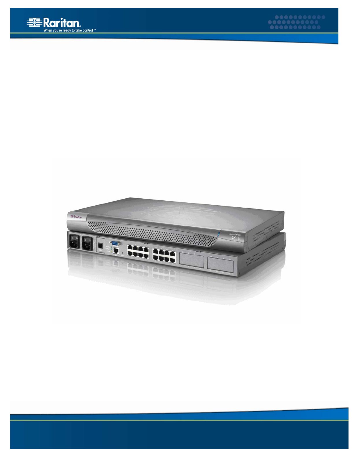
Figure 1 Dominion SX16 Unit....................................................................................................................... 1
Figure 2 Rear Panel of the DSXA-32 ........................................................................................................... 6
Figure 5 Certificate Information.................................................................................................................... 7
Figure 6 DSX Login Screen .........................................................................................................................8
Figure 7 Restricted Service Agreement Screen ........................................................................................... 8
Figure 8 Change Password Screen ............................................................................................................. 8
Figure 9 Dominion SX Port Access Screen for Operators/ Observers ....................................................... 11
Figure 10 Dominion SX Port Access Screen for Administrators................................................................. 11
Figure 11 Setup Screen .............................................................................................................................11
Figure 12 Date / Time Configuration Screen.............................................................................................. 12
Figure 13 Network Configuration Screen ...................................................................................................13
Figure 14 Network Basic Settings and Ports Screen ................................................................................ 15
Figure 15 Network Service Settings.......................................................................................................... 17
Figure 16 Modem Settings Screen............................................................................................................ 18
Figure 17 IP Forwarding Panel ..................................................................................................................18
Figure 18 Static Routes List ....................................................................................................................... 19
Figure 19 Static Route Screen .................................................................................................................. 19
Figure 20 User List Screen ....................................................................................................................... 21
Figure 21 New User Screen...................................................................................................................... 22
Figure 22 Group List Screen ..................................................................................................................... 24
Figure 23 New Group Screen ................................................................................................................... 24
Figure 24 RADIUS Panel .......................................................................................................................... 27
Figure 25 LDAP Panel ..............................................................................................................................28
Figure 26 TACACS+ Panel ....................................................................................................................... 29
Figure 27 Port Keywords Screen ...............................................................................................................31
Figure 28 Port Configuration Screen.......................................................................................................... 32
Figure 29 Edit Port Screen........................................................................................................................ 33
Figure 30 Direct Port Access Mode Field................................................................................................... 34
Figure 31 Port Access Screen ................................................................................................................... 35
Figure 34 Java Runtime Settings ............................................................................................................... 36
Figure 35 Raritan Serial Client Window .....................................................................................................38
Figure 36 Emulator Drop-Down Menu ....................................................................................................... 39
Figure 37 Connection Terminated Warning ...............................................................................................39
Figure 38 General Settings Window .......................................................................................................... 40
Figure 39 Display Settings Window ...........................................................................................................41
Figure 40 Display Settings: GUI Font Properties .......................................................................................42
Figure 43 Connected Users Window ......................................................................................................... 44
Figure 45 Edit Commands - Copy, Paste, and Select All Text................................................................... 45
Figure 46 Tools Menu ................................................................................................................................ 46
Figure 47 Start Logging Command Window .............................................................................................. 47
Figure 48 Send Keystroke.......................................................................................................................... 48
Figure 50 SecureChat Command and User Chat Window......................................................................... 49
Figure 52 Sample of the About Raritan Serial Console Window ................................................................ 50
Figure 53 Windows OS: System Properties............................................................................................... 51
Figure 54 Windows OS: New System Variable.......................................................................................... 52
Figure 55 Windows OS: Edit System Variable........................................................................................... 53
Figure 56 Windows OS: CLASSPATH Variable......................................................................................... 53
Figure 57 Check JRE Version in Sun Solaris............................................................................................. 54
Figure 60 RSC Windows Install Progress Screen...................................................................................... 55
Figure 61 RSC Windows Shortcut Screen ................................................................................................. 56
Page 12

viii DOMINION SX USER GUIDE
Figure 63 Standalone RSC Login Screen ..................................................................................................56
Figure 64 Standalone RSC Connected to Port Window............................................................................. 57
Figure 67 Security Settings Screen............................................................................................................ 59
Figure 68 Login Settings Screen................................................................................................................ 60
Figure 69 Kerberos Settings ......................................................................................................................61
Figure 70 Certificate Signing Request ....................................................................................................... 62
Figure 71 Install User Key.......................................................................................................................... 63
Figure 72 Install User Certificate................................................................................................................ 63
Figure 73 SSL Client Certificate Screen .................................................................................................... 65
Figure 74 Banner Screen........................................................................................................................... 67
Figure 75 Security Profiles......................................................................................................................... 68
Figure 76 Edit Custom Security Profile Screen .......................................................................................... 69
Figure 77 Firewall Screen ..........................................................................................................................70
Figure 78 Event Log Panel........................................................................................................................ 71
Figure 79 System Logging Panel .............................................................................................................. 71
Figure 80 Port Logging Panel ...................................................................................................................72
Figure 81 Sample Output File ...................................................................................................................73
Figure 82 Input Port Logging Panel ........................................................................................................... 74
Figure 83 Encryption Panel....................................................................................................................... 74
Figure 84 SMTP Settings Panel................................................................................................................ 75
Figure 85 New SMTP Event Panel ...........................................................................................................75
Figure 86 NFS Settings Screen ................................................................................................................77
Figure 87 SNMP Settings Panel ................................................................................................................78
Figure 88 SNMP Destination Panel .......................................................................................................... 78
Figure 89 Event Log.................................................................................................................................. 79
Figure 90 Send Event Log Screen ............................................................................................................ 80
Figure 91 Backup Screen.......................................................................................................................... 81
Figure 92 Restore Screen ......................................................................................................................... 82
Figure 93 Firmware Version...................................................................................................................... 83
Figure 94 Firmware Upgrade Screen......................................................................................................... 84
Figure 95 Firmware Upgrade History Screen............................................................................................. 84
Figure 96 Diagnostics Screen .................................................................................................................... 87
Figure 97 Active Network Interface Status ................................................................................................. 87
Figure 98 Network Statistics ......................................................................................................................88
Figure 99 Ping Host ................................................................................................................................... 89
Figure 100 Trace Route to Host................................................................................................................. 89
Figure 101 Process Status......................................................................................................................... 90
Figure 102 Sample Administrator Login..................................................................................................... 97
Figure 103 Sample Operator or Observer Login ........................................................................................ 97
Figure 104 IPMI Screen ...........................................................................................................................153
Figure 105 Discover IPMI Devices Screen............................................................................................... 153
Figure 106 IPMI Configuration ................................................................................................................. 154
Figure 107 Port Power Association Screen.............................................................................................. 157
Figure 108 Power Strip Configuration Screen.......................................................................................... 158
Figure 109 Power Association Group Screen ......................................................................................... 159
Figure 110 Power Control ........................................................................................................................159
Figure 111 Associations Power Control ...................................................................................................160
Figure 112 Power Strip Power Control..................................................................................................... 161
Figure 113 Power Strip Status ................................................................................................................. 162
Figure 114 Cisco ACS AAA Client for TACACS+ .................................................................................... 191
Figure 115 Cisco ACS Interface Configuration ........................................................................................192
Figure 116 TACACS+ Properties ............................................................................................................. 192
Figure 117 Dial-Up Networking Display ................................................................................................... 195
Page 13

FIGURES IX
Figure 118 New Phone Entry Display ...................................................................................................... 196
Figure 119 Dial-Up Security Display ........................................................................................................ 197
Figure 120 Windows 2000 Network and Dial-Up Connections................................................................. 197
Figure 122 Network Connection Type...................................................................................................... 198
Figure 123 Device Selection .................................................................................................................... 198
Figure 124 Phone Number to Dial............................................................................................................ 199
Figure 125 Connection Availability........................................................................................................... 199
Figure 128 Network Connection Type...................................................................................................... 200
Figure 129 Device Selection .................................................................................................................... 200
Figure 130 Internet Connection................................................................................................................ 201
Figure 131 Connection Name .................................................................................................................. 201
Figure 132 Phone Number to Dial............................................................................................................ 202
Figure 133 Internet Account Information.................................................................................................. 202
Page 14

x DOMINION SX USER GUIDE
Tables
Table 1 Factory Default Network Settings.................................................................................................... 5
Table 2 Java Runtime Parameters............................................................................................................. 37
Table 3 Commands Common to All CLI Levels ......................................................................................... 99
Table 4 Available CLI Commands............................................................................................................ 101
Table 5 Configuration: Authentication Commands: ldap .......................................................................... 105
Table 6 LDAP Command .........................................................................................................................106
Table 7 Configuration: Events Commands............................................................................................... 107
Table 8 Eventlogfile Command ................................................................................................................ 108
Table 9 Eventsyslog Command ............................................................................................................... 108
Table 10 nfsget Command....................................................................................................................... 109
Table 11 nfssetkey Command ................................................................................................................ 109
Table 12 Portlog Command ..................................................................................................................... 110
Table 13 Sendeventlog Command........................................................................................................... 111
Table 14 Configuration: Modem Commands............................................................................................ 111
Table 15 Configuration: Network Commands .......................................................................................... 114
Table 16 Interface Command................................................................................................................... 114
Table 17 Ipforwarding Command............................................................................................................. 115
Table 18 name Command........................................................................................................................ 115
Table 19 ports Command......................................................................................................................... 115
Table 20 Route Command ....................................................................................................................... 116
Table 21 Routeadd Command ................................................................................................................. 116
Table 22 Routedelete Command ............................................................................................................. 116
Table 23 NFS Command .........................................................................................................................117
Table 24 Port Configuration Command.................................................................................................... 118
Table 25 Port Keywordadd Command ..................................................................................................... 120
Table 26 Port Keyworddelete Command .................................................................................................120
Table 27 dpa Command .......................................................................................................................... 121
Table 28 Encryption Command................................................................................................................ 123
Table 29 HTTP Command ....................................................................................................................... 123
Table 30 Lpa Command .......................................................................................................................... 124
Table 31 SSH Command .........................................................................................................................125
Table 32 Telnet Command....................................................................................................................... 125
Table 33 SNMP Add Command............................................................................................................... 126
Table 34 SNMP Delete Command........................................................................................................... 126
Table 35 SNMP Command ......................................................................................................................127
Table 36 Clock Command........................................................................................................................ 127
Table 37 ntp Command ........................................................................................................................... 128
Table 38 Addgroup Command ................................................................................................................. 129
Table 39 Adduser Command ................................................................................................................... 129
Table 40 Deletegroup Command ............................................................................................................. 130
Table 41 Deleteuser Command ............................................................................................................... 130
Table 42 Editgroup Command ................................................................................................................. 130
Table 43 Edituser Command ................................................................................................................... 131
Table 44 Connect Commands ................................................................................................................. 132
Table 45 Diagnostics Commands ............................................................................................................ 132
Table 46 IPMIDiscover Command ........................................................................................................... 133
Table 47 IPMITool Command .................................................................................................................. 134
Table 48 Listports Command ................................................................................................................... 136
Table 49 Backup Command..................................................................................................................... 137
Table 50 Logoff Command....................................................................................................................... 138
Table 51 Password Command................................................................................................................. 138
Page 15

TABLES XI
Table 52 Restore Command .................................................................................................................... 139
Table 53 Sendeventlog Command........................................................................................................... 140
Table 54 Upgrade Command................................................................................................................... 140
Table 55 Banner Command ..................................................................................................................... 142
Table 56 ftpgetbanner Command ............................................................................................................ 142
Table 57 Certificate Client Commands .................................................................................................... 143
Table 58 Certificate Server Commands ................................................................................................... 143
Table 59 Firewall Command ................................................................................................................... 144
Table 60 iptables Command .................................................................................................................... 144
Table 61 Kerberos Commands ................................................................................................................ 146
Table 62 Loginsettings Commands.......................................................................................................... 147
Table 63 Inactiveloginexpiry Command ................................................................................................... 148
Table 64 Invalidloginretries Command..................................................................................................... 148
Table 65 Lockoutperiod Command .......................................................................................................... 149
Table 66 Singleloginperuser Command................................................................................................... 149
Table 67 Strongpassword Command....................................................................................................... 150
Table 68 unauthorizedportaccess Command........................................................................................... 150
Table 69 Securityprofiles Commands ...................................................................................................... 151
Table 70 Profiledata Command ............................................................................................................... 151
Table 71 Dominion SX Specifications ...................................................................................................... 167
Table 72 Dominion SX Dimensions and Weight ...................................................................................... 168
Table 73 Dominion SX Requirements...................................................................................................... 169
Table 74 Browser Requirements.............................................................................................................. 169
Table 75 Connectivity .............................................................................................................................. 170
Table 76 Dominion SX RJ-45 Serial Pinouts and Signals ........................................................................ 171
Table 77 DB9F Nulling Serial Adapter Pinouts ........................................................................................ 171
Table 78 DB9M Nulling Serial Adapter Pinouts........................................................................................ 172
Table 79 DB25F Nulling Serial Adapter Pinouts ...................................................................................... 172
Table 80 DB25M Nulling Serial Adapter Pinouts...................................................................................... 172
Table 81 Dominion SX Terminal Port Pinouts-First Port ..........................................................................173
Table 82 Dominion SX Terminal Port Pinouts-Second Port ..................................................................... 173
Table 83 Dominion SX16 and SX32 Terminal Port Pinouts ..................................................................... 174
Table 84 Dominion SX System Defaults .................................................................................................. 175
Table 85 Initiating Port Access................................................................................................................. 176
Table 86 Troubleshooting Page Access .................................................................................................. 203
Table 87 Troubleshooting Firewall ...........................................................................................................204
Table 88 Troubleshooting Login............................................................................................................... 205
Table 89 Troubleshooting Port Access .................................................................................................... 205
Table 90 Troubleshooting Upgrade.......................................................................................................... 206
Table 91 Troubleshooting Modem ........................................................................................................... 206
Page 16

xii DOMINION SX USER GUIDE
Preface
The Dominion SX User Guide provides the information needed to install, set up and configure,
access devices such as routers, servers, switches, VPNs, and power strips, manage users and
security, and maintain and diagnose the Dominion SX secure console server.
Audience
The primary audiences for this guide are infrastructure administrators and installers who are
responsible for installing and setting up devices such as secure console servers. Other interested
audiences are operators and observers who use the Dominion SX to reach other devices.
Conventions
This guide uses the following conventions:
EXAMPLE DESCRIPTION
/usr/local/java
Enter
<ip address>
Monospaced text indicates file names, paths, directories, or screen text.
Menu items, Key words and Keyboard keys are bolded.
Monospaced, italicized text indicate where the user would substitute a
value in a command.
Acronyms
This guide uses the following acronyms:
ACRONYM MEANING
AD Active Directory
CC Command Center
CLI Command Line Interface
CSC Common Socket Connection
DPA Direct Port Access
HTTP Hypertext Transfer protocol
HTTPS HTTP Secure (over SSL)
LAN Local Area Network
LDAP Lightweight Directory Access Protocol
LDAP/S Lightweight Directory Access Protocol/Secure
NFS Network File System
NTP Network Time Protocol
PPP Point to Point Protocol
RADIUS Remote Authentication Dial In User Service
RSC Raritan Serial Console
SMTP Simple Mail Transfer Protocol
SSH Secure Shell
SSL Secure Sockets Layer Protocol
SNMP Simple Network Management Protocol
TACACS+ Terminal Access Controller Access Control System (PLUS)
TLS Transport Layer Security
UTC Universal Time Coordinated
VLAN Virtual Local Area Network
Page 17

PREFACE XIII
ACRONYM MEANING
VPN Virtual Private Network
Notices
Important: cautionary information that warns of possible affects on the users,
corruption risks, and actions that may affect warranty and service coverage.
Note: general information that is supplemental to the text.
Page 18

This page intentionally left blank.
Page 19
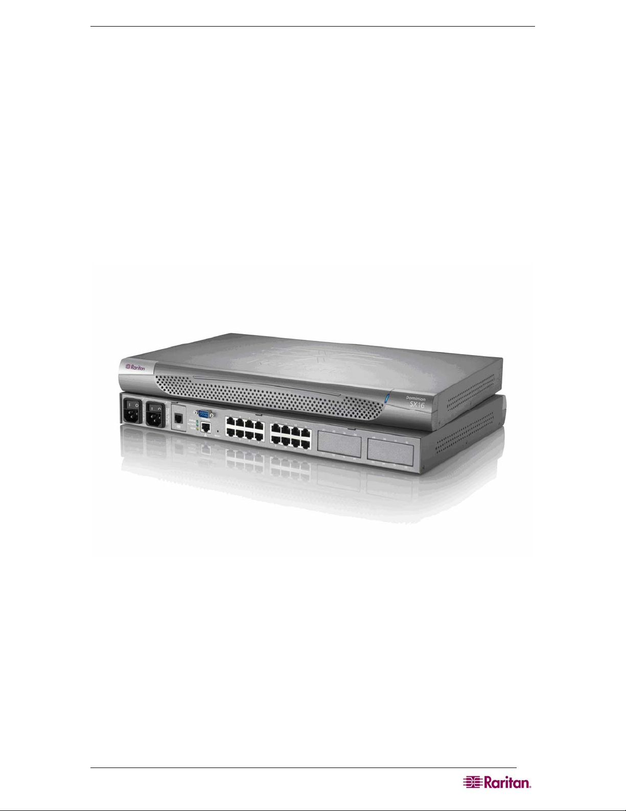
CHAPTER 1: INTRODUCTION 1
Chapter 1: Introduction
Dominion SX Overview
The Dominion SX Series of Serial over IP Console Servers offers convenient and secure, remote
access and control through LAN/WAN, Internet, or Dial-up modem to all networking devices.
The Dominion SX:
• Provides a non-intrusive solution for managing network elements and does not require any
installation of software agents on the target device.
• Connects to any networking device (servers, firewalls, load balancer, and so forth) through
the serial port and provides the ability to remotely and securely manage the device using a
Web browser.
Dominion SX is a fully configured stand-alone product in a standard 1U high 19” rack mount
chassis.
Figure 1 Dominion SX16 Unit
Page 20

2 DOMINION SX USER GUIDE
Product Features
Comprehensive Console Management
• Remote Management: Access, monitor, administer, and troubleshoot up to 48 target devices
(depending on the model) via Secure Socket Shell (SSH), Telnet, Local Port or Web browser
with only one IP address.
• Direct Port Access via TCP/IP address per port; or one IP address and TCP Port numbers.
• Notification: Create notification messages by email alerts.
• Collaborative Management and Training: Access ports simultaneously; up to 10 users per
port at any time.
• SecureChat™: “Instant message” and other Secure Sockets Layer (SSL) users can securely
collaborate on device management, troubleshooting, and training activities.
• Get History: Get up to 256 KB (64KB on units with 64MB SDRAM; 256KB on units with
128MB SDRAM) of recent console history to assist with debugging.
• Supports VT100, VT220, VT 320, and ANSI terminal emulation.
• Up to a 5,000 line copy-paste buffer.
• Local port access.
• SNMP traps.
• SYSLOG.
• Logging to Network File System (NFS) Server.
• Comprehensive SNMP traps.
• Port alerts with keyword triggers.
• Three Levels of User Access:
o Administrator: Has read and write access to the console window; can modify the
configuration of unit.
o Operator: Has read and write access to the console window; cannot modify the
configuration of unit (except own password).
o Observer: Has read-only access to the console window; cannot modify the configuration
of unit (except own password).
Strong Security and User-Authentication
• SSHv2 Support
• Encryption Security: 128-bit SSL handshake protocol and RC4 encryption.
• User Authentication Security: local database, remote authentication
• Supports RADIUS, TACACS+, LDAP, LDAP(S), Microsoft Active Directory, and NTP.
• Supports user-defined and installable security Certificates.
Reliable Connectivity
• Optional Modem Connectivity: For emergency remote access if the network has failed.
• Target Device Connectivity: Simplified RJ45-based CAT 5 cable scheme; serial port adapters
are available from Raritan.
• Local Access for “crash-cart” applications.
Simplified User Experience
• Telnet
• SSH
• Browser-based Interface: The new GUI provides intuitive access to target devices (click on
the appropriate button to select the desired target device).
• Upgrades: Built-in firmware upgrade capability through FTP and integrated with Command
Center (CC) and SSH.
Page 21

CHAPTER 1: INTRODUCTION 3
Package Contents
Each Dominion SX ships with the following:
• (1) Dominion SX unit with mounting kit (Rack-mount kit is optional on some units)
• (1) Raritan Dominion SX User Guide CD-ROM, which contains the installation and
operations information for the Dominion SX
• (1) Printed Dominion SX Quick Setup Guide
• (1) Power cord
• (1) Release Notes
• (1) Packing List page
• (1) RJ45 serial loop-back plug
• A DB9 Factory Reset Adapter for some units (Other units have a reset switch and do not
require an adapter).
Page 22

4 DOMINION SX USER GUIDE
This page intentionally left blank.
Page 23

CHAPTER 2: INSTALLATION 5
Chapter 2: Installation
There are two ways of completing the initial network installation of the Dominion SX:
• Using a serial cable with a VT100/equivalent, such as a PC with HyperTerminal.
• Using Ethernet (with an installation computer).
This section describes the steps necessary to configure Dominion SX for use on a local area
network (LAN). The following table describes the factory default network settings that come with
the Dominion SX. After units are connected to the network, these factory default settings allow
you to configure the Dominion SX for normal use.
Table 1 Factory Default Network Settings
DEFAULT NETWORK SETTINGS
Internet Address (IP) 192.168.0.192
Gateway Address 192.168.0.192
Subnet Mask 255.255.255.0
CSC Port Address 5000
Port Address for CC Discovery 5000
Username admin (all lowercase)
Password raritan (all lowercase)
Pre-Installation
Ensure that you have the correct cabling ready to connect to the serial consoles of the target
server (s) or other serially managed devices that provide a console port.
The following sections describe information that you must supply to complete the configuration
of the Dominion SX. Obtain all required configuration information prior to performing the
configuration steps. If you are uncertain of any information, contact your system administrator for
assistance.
Client Configuration
1. Disable Proxies in the installation computer Web browser.
Use “no Proxies” or temporarily add 192.168.0.192 to the list of URLs for which no proxy is
configured.
2. Enable Java Applet Execution in the installation computer Web browser for the console
client application (RSC).
3. Access the unit through your installation computer Web browser on the same subnet by
typing the URL https://192.168.0.192 into the address/location field.
Page 24
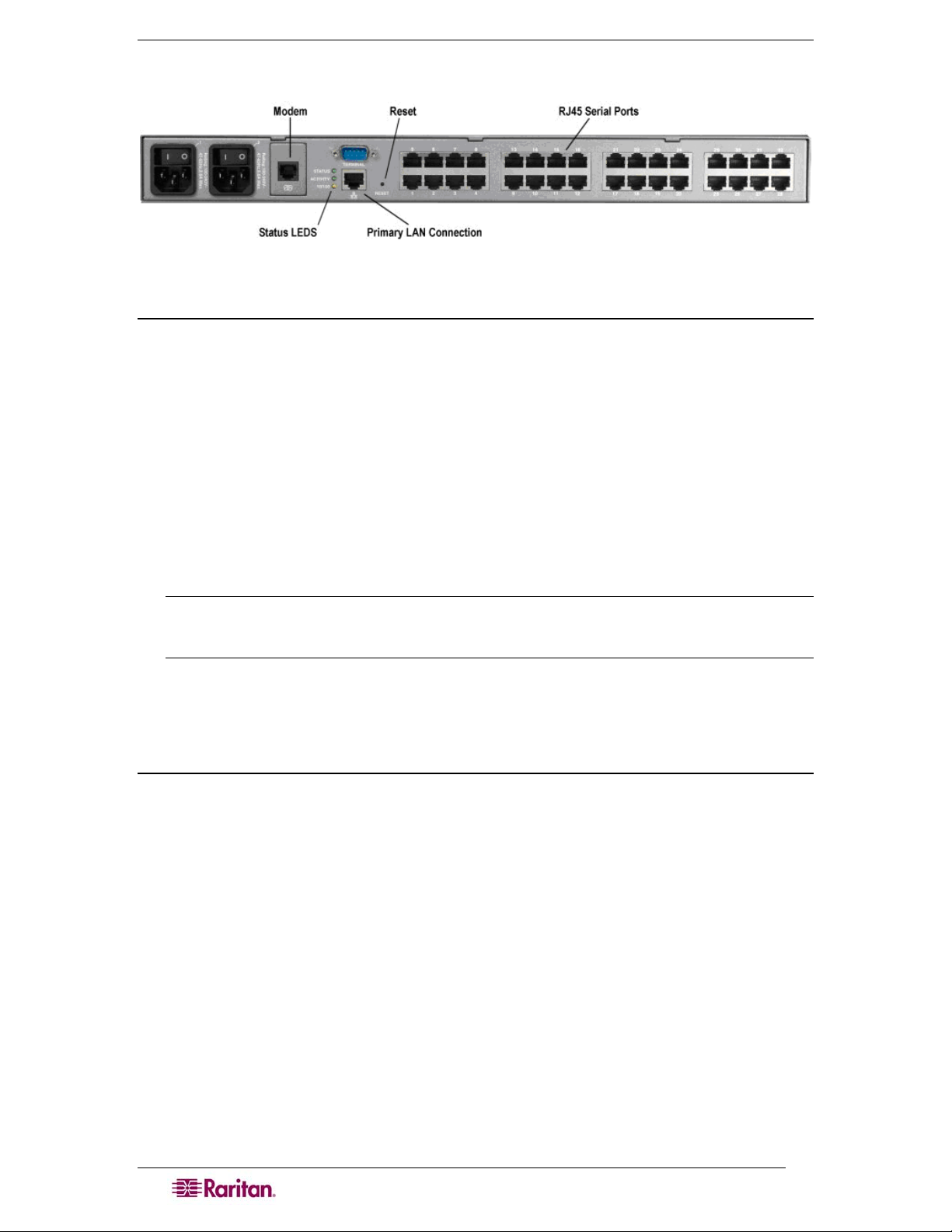
6 DOMINION SX USER GUIDE
Hardware Installation
Figure 2 Rear Panel of the DSXA-32
Physical Installation of Dominion SX for Initial Configuration
1. Use a computer with a network card and crossover network cable. This computer will be
referred to as the ‘installation computer.’
2. Physically mount the unit in an ergonomically sound manner. The unit is designed to be
easily rack-mounted, and rack mounting is recommended.
3. Connect the crossover network LAN cable to the primary LAN connection (LAN 1 on
models with two Ethernet interfaces) on the back of the chassis.
4. Connect the other end of the network LAN cable to the network card in the installation
computer.
5. Connect the female end of the external power cord to the back of the chassis.
6. Connect the male end of the external power cord to the power supply outlet.
7. Power ON the Dominion SX unit.
Note: The unit will perform a hardware and firmware self-test then start the software boot
sequence, which takes a short time and is complete when the light turns on and remains
on.
After completion of the hardware and firmware self-test and the software boot sequence, perform
the initial configuration tasks using the Graphical User Interface (GUI) or the Command
Language Interface (CLI) as described in the following sections.
LED State
On the front panel of the Dominion SX unit, there exists a LED indicator right next to the model
name label. The LED indicator will blink blue in the following three cases:
1. Ethernet packets are received or transmitted.
2. Serial data are received or transmitted.
3. When watchdog timer is reset to 0. The LED blinks on a periodic basis as the watchdog
timer reaches a certain value, and then is reset to 0.
Page 25
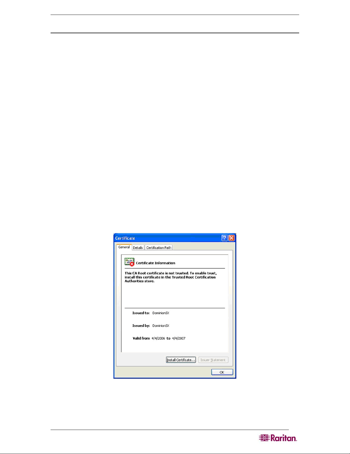
CHAPTER 2: INSTALLATION 7
Initial Configuration Using the Graphical User Interface (GUI)
To initially configure the Dominion SX unit from the Graphical User Interface, follow the steps
below.
Network Access
1. Ensure that the installation computer has the route for 192.168.0.192 and that it can
communicate with IP address 192.168.0.192.
2. To check the route table in Windows, type the command route print in a Command
window on the installation computer. If 192.168.0.192 is on the gateway list, proceed to step
3. Otherwise, add 192.168.0.192 to the gateway list using the appropriate DOS or UNIX CLI
command:
• Windows 98/2000/NT system: route add 192.168.0.192
<INSTALLATION COMPUTER IP ADDRESS>.
[Example: route add 192.168.0.192 15.128.122.12
• UNIX (including Sun Solaris) system:
route add 192.168.0.192 <CLIENT_HOST IP ADDRESS> -interface.
[Example: route add 192.168.0.192 15.128.122.12 –interface]
3. Type ping 192.168.0.192. Go to step 4 if you receive a successful reply from the
Dominion SX unit. If an error occurs, verify that the default IP address is entered correctly
and that a route to that IP address exists.
4. Use the installation computer to connect to the unit by launching a browser and typing the
factory default IP address 192.168.0.192 in the Web browser’s address box.
5. The computer displays the security screens before you can log in.
6. If you click View Certificate on the Security Alert-Certificate screen a Certificate screen
appears.
Figure 3 Certificate Information
See Chapter 8: Security and Appendix C: Certificates for information about installing
certificates.
Page 26
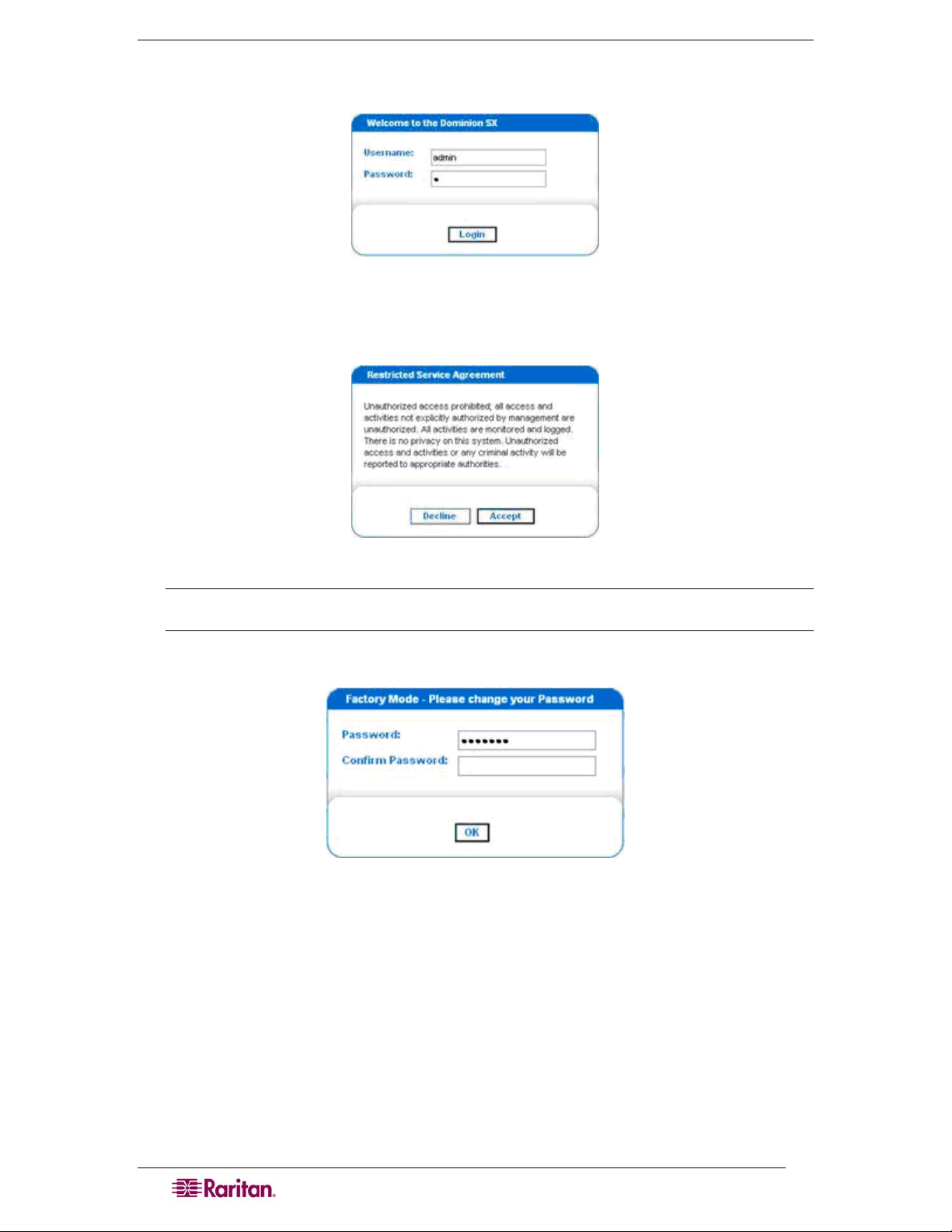
8 DOMINION SX USER GUIDE
The login screen appears after you finish viewing the security alerts and the Certification
Information screen.
Figure 4 DSX Login Screen
7. Log in with the default username admin and password raritan. Use all lowercase letters. A
Restricted Service Agreement Screen appears:
Figure 5 Restricted Service Agreement Screen
Note: Once you click Accept after login, the Dominion SX prompts you to change the
default password.
A Change Password screen appears:
Figure 6 Change Password Screen
8. Type a new secure password then retype it (Remember the new password).
9. Click OK.
10. Click Exit.
11. Log in again using your new password.
The Dominion SX Port Access Screen appears. (See
Chapter 3: Initial Software
Configuration)
Page 27

CHAPTER 2: INSTALLATION 9
Initial Configuration Using the Command Line Interface
To initially configure the Dominion SX unit from the Command Line Interface, follow the steps
below.
1. Connect the serial port of your Installation Computer to the Terminal serial port on your
Dominion SX. This port is a DB9-Male port on most models, except ALL dual-power dualLAN models, including DSXA-48, which have an RJ45 connector for a terminal port.
2. Open a terminal emulation program, such as HyperTerminal, to connect to the Dominion SX
unit. The serial communication parameters are 9600 bps, No parity, 8 data bits, 1 stop bit and
None flow control.
3. Power ON the Dominion SX.
4. Log in using the default username admin and the default password raritan when prompted.
Once logged in a prompt to change the password appears.
5. Type a new password, and then retype it (Remember this password).
A display will appear showing the Dominion SX unit’s status and serial channel ports.
Note: If the password entered does not follow the password rules, an error message will
appear as a warning. The user will then be logged out and need to start over again for
password setting.
Network Access
1. Ensure that the installation computer has the route for 192.168.0.192 and that it can
communicate with IP address 192.168.0.192.
2. To check the route table in Windows, type the command route print in a Command
window on the installation computer. If 192.168.0.192 is on the gateway list, proceed to step
3. Otherwise, add 192.168.0.192 to the gateway list using the appropriate DOS or UNIX CLI
command:
• Windows 98/2000/NT system: route add 192.168.0.192
<INSTALLATION COMPUTER IP ADDRESS>.
[Example: route add 192.168.0.192 15.128.122.12
• UNIX (including Sun Solaris) system:
route add 192.168.0.192 <CLIENT_HOST IP ADDRESS> -interface.
[Example: route add 192.168.0.192 15.128.122.12 –interface]
3. Type ping 192.168.0.192. Go to step 4 if you receive a successful reply from the
Dominion SX unit. If an error occurs, verify that the default IP address is entered correctly
and that a route to that IP address exists.
4. Use the installation computer to connect to the unit by launching a browser and typing the
factory default IP address 192.168.0.192 in the Web browser’s address box.
Set Date and Time
1. Type Configuration to change the unit’s configuration.
2. Type Time to select the Date / Time configuration.
3. Type Timezonelist and find the number code that corresponds to your time zone.
4. Type clock [tz timezone] [datetime datetime-string]. The following is an
example:
admin > Config > Time > clock tz 9 datetime “2007-02-05
09:22:33”
In this example, 9 is the time zone code (Step 3) and “2007-02-05 09:22:33” the
date/time string in the format “YYYY-MM-DD HH:MM:SS” (quotes required).
Network Configuration
Page 28

10 DOMINION SX USER GUIDE
1. Type Configuration to change the unit’s configuration.
2. Type Network to select the network configuration.
3. Type:
admin > Config > Network > interface enable true if lan1 ip
192.16.151.12 mask 255.255.255 gw 192.168.51.12
.Upon successfully entering the data, a report will display the new network configuration and you
will be prompted to reboot the unit.
4. Type yes to reboot the Dominion SX.
5. You can now remove the serial cable.
6. Reconnect from the installation computer browser to the Dominion SX using the new IP
address and password and proceed.
User Configuration
1. Type Configuration to change the unit’s configuration.
2. Type Users to select the user configuration.
To add a user group
Type
addgroup name <group name> class <class type> ports <n1,n2,n3...>
where <group name> is the name of the group and <class type> is
• Op for operator
• Ob for observer.
<n1,n2,n3...> is a list of port numbers this group has access to, separated by comas and no
spaces. You could configure port ranges using the same parameters as well, or use the wildcard
asterisk (*). For example:
• “config port 3-7 exitstring #0”(this disables exit strings for ports
3,4,5,6,7)
• config port * bps 115200 (this sets all ports to a communications speed of
115200 bps)
To add a user
1. Type
adduser user <user name> fullname <full name> group <group name>
password <password> info <information> dialback <dialback number>
active <status>
...
where <user name> is user’s login name,
<full name> is a user’s descriptive name (no spaces),
<group name> is the user’s assigned group,
<password> is the user’s password,
<information> is extra information (optional, no spaces),
<dialback number> is the user’s phone number (optional),
<status> is true or false, allowing the user to login or not.
2. Type top to return to the top level of the CLI menu.
Page 29
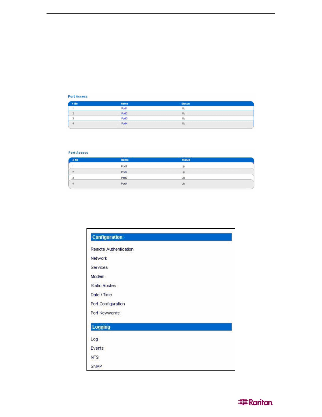
CHAPTER 3: INITIAL SOFTWARE CONFIGURATION 11
Chapter 3: Initial Software Configuration
After the hardware installation, perform the initial software configuration. Do this by logging
onto the Dominion SX from either a browser or through a Command Line Interface (See Chapter
12: Command Line Interface for CLI information.)
Dominion SX Initial Software Configuration
1. Log on to the Dominion SX using your new password. A Port Access screen appears
according to your user type:
Figure 7 Dominion SX Port Access Screen for Operators/ Observers
Figure 8 Dominion SX Port Access Screen for Administrators.
2. Click the Setup tab. The Setup screen appears. It contains links to the Configuration and
Logging screens.
Figure 9 Setup Screen
Page 30
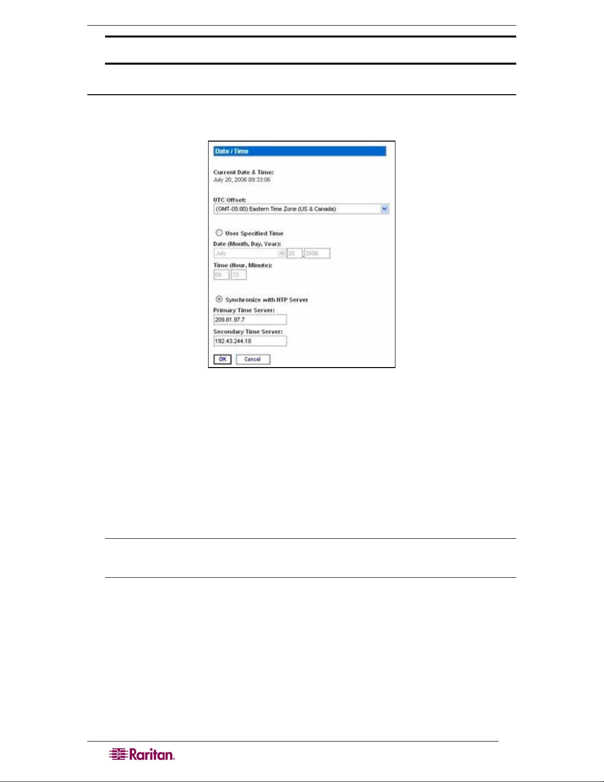
12 DOMINION SX USER GUIDE
Important: After you complete each configuration task, you must return to the Setup tab to
perform the next configuration task.
Date / Time Configuration
1. Click the Date / Time in the Configuration section of the Setup Screen. The Date / Time
Configuration screen appears.
Figure 10 Date / Time Configuration Screen
2. Select the correct time zone from the UTC Offset drop-down menu.
3. Choose one of the following:
• User Specified Time – Click this radio button and enter the date and time manually
in the corresponding fields.
• Synchronize with NTP Server – Click this radio button and enter the IP address of a
Network Time Protocol (NTP) server in the Primary Time Server. If you have a
backup NTP server, enter its IP address in the Secondary Time Server field.
4. Type the Interface Name in the Interface field.
5. Click OK.
Note: Features such as certificate generation depend on the correct Timestamp, used to
check the validity period of the certificate. In addition, the Syslog and NFS logging
features also use the system time for time-stamping log entries.
After you click OK, the system displays one of the following screens:
• A confirmation screen, which contains the settings you chose and a confirmation message
at the top of the screen.
Date / Time Settings successfully applied.
• An error screen, which contains the original Date / Time screen and the error message.
ERROR: Date / Time Settings NOT successfully applied.
Page 31

CHAPTER 3: INITIAL SOFTWARE CONFIGURATION 13
Network Configuration
1. Click Network in the Configuration section of the Setup screen. The Network Configuration
Screen appears.
Note: If you have a dual LAN model, there is an Eth Failover checkbox that is selected by
default, but can be turned off. The screen below represents a single LAN model and does
not show this checkbox.
Figure 11 Network Configuration Screen
Note: Your network administrator usually assigns the values for the following parameters:
2. Type the data in the following fields:
• IP Address: Network address for this unit
• Subnet Mask: Subnet mask for the network where this unit will reside
• Gateway IP Gateway: Default gateway for this unit
3. Select the Mode from the Mode drop-down menu.
4. Type the Domain Name in the Domain field.
5. Type your Unit Name in the Unit Name field.
6. In the Ports section:
• Type 5000 or another port number in the CSC Port field.
• Type 5000 or another port number in the Discovery Port field.
7. Click OK.
Dominion SX displays either a confirmation or error screen.
1. Click OK when the confirmation window appears. After the confirmation screen, Dominion
SX automatically disconnects to update the configuration then restarts.
2. Remove the crossover cable between the SX unit and your computer.
3. Connect one end of a straight-through Cat 5 cable to the SX.
4. Connect the other end of the cable to the network.
5. Use the newly assigned IP Address to access your SX unit.
Page 32

14 DOMINION SX USER GUIDE
Deployment
1. You can remotely access the Dominion SX through a: LAN connection or a modem
connection (optional).
2. The Dominion SX can access target devices only through a serial connection.
LAN Connection
After the initial software configuration phase, configure the DSX unit for operation on the LAN.
1. Ensure that you have an Ethernet cable connected to the network for use with the unit.
2. Physically mount the unit in an ergonomically sound manner.
3. Connect the LAN cable to the primary LAN connection (LAN 1) on the back of the chassis.
If the unit has a failover module, connect the secondary network LAN connection (LAN 2).
4. Perform a quick connectivity check by connecting to the device using the Web browser.
5. Enter https://<IPAddress> in the address line, where <IPAddress> is the IP address of
the unit as previously configured.
The login display should appear verifying that the unit has been properly configured and
can be accessed from the network.
6. Log in with username admin and the password you created earlier.
7. From the Home page, click the Setup tab and select the various configuration options for
configuring the DSX and each console port.
Modem Connection (Optional)
To configure the DSX for a modem connection:
1. Connect a phone line to the modem port.
2. Write down the phone number for this line because it will be needed when you configure a
client for dialup networking.
See
Appendix E: Modem Configuration for more information.
Page 33

CHAPTER 4: NETWORK SETTINGS AND SERVICES 15
Chapter 4: Network Settings and Services
This chapter explains how to configure the basic network settings for the DSX, and how to
configure the various access protocols (SSH, telnet, etc.) It also explains how to configure the
DSX for modem access, and how to enable IP forwarding and create static routes.
Configuring the Basic Network Settings
To configure the basic network settings and discovery ports, click the Setup tab, and then click
Network. The Network Basic Settings and Ports screen appears (
Figure 12).
Figure 12 Network Basic Settings and Ports Screen
Give the DSX a Name
To give the DSX unit a name to help identify it:
1. Type a name in the Unit Name field.
2. Click OK.
Configure the DSX’s Network Settings
To configure the network settings:
1. Type an IP address for the DSX in the IP Address field.
2. Type the subnet mask in the Subnet Mask field.
3. Type the IP address of the gateway router in the Gateway IP Address field.
4. Select the speed from the drop-down menu in the Mode field. Your choices are Auto
(default) or 100 Mbps.
5. Type your domain name in the Domain field.
6. Click OK.
Page 34

16 DOMINION SX USER GUIDE
Change the Discovery Ports
The DSX has two discovery ports:
• TCP 5000 Common Socket Connection (CSC) discovery
• UDP 5000 Command Center (CC) discovery
If either of these ports is used by another application, you can change the discovery port number
in the DSX in the appropriate field and click OK.
Configuring the Network Service Settings
The table below indicates the default settings for the various network access services:
Service Default Setting
HTTP Enabled. The default port is 80. This can be changed.
HTTPS redirect is enabled by default. If HTTPS is also enabled, all HTTP
requests are automatically redirected to the HTTPS port (see below).
HTTPS Enabled. The default port is 443. This can be changed.
Encryption is set to SSL, but this can be changed to TLS.
Telnet Disabled for security reasons. This can be enabled and the port configured.
Local Port Access Enabled. The baud rate is set to 9600 bps, but this can be changed.
Direct Port Access Set to IP, but this can be changed to Normal or TCP port.
Page 35

CHAPTER 4: NETWORK SETTINGS AND SERVICES 17
To change any of these network service settings:
1. Click the Setup tab, and then click Services. The Network Service Settings screen appears.
Figure 13 Network Service Settings
2. Make any necessary changes to the appropriate fields.
3. Click OK.
Page 36

18 DOMINION SX USER GUIDE
Configuring Modem Access
You can access the DSX via a modem. To set this up:
1. Click the Setup tab, and then click Modem. The Modem Settings screen appears.
Figure 14 Modem Settings Screen
2. Click the checkbox labeled Enable Modem to enable modem access.
3. Type the IP addresses of the Point-to-Point (PPP) server in the PPP Server IP field. The
default is 10.0.0.1
4. Type the IP address of the PPP client in the PPP Client IP field. The default is 10.0.0.2.
5. If you want to enable modem dialback, click the Enable Modem Dial Back checkbox.
6. Click OK. Modem access is enabled.
Configuring IP Forwarding and Static Routes
You can enable IP forwarding. You can also create static routes if your DSX has two LAN ports
or is configured for modem access.
Enable IP Forwarding
To enable IP forwarding:
1. Click the Setup tab, and then click Static Routes. The Static Routes screen appears. It
consists of an Enable IP Forwarding panel and a Static Routes List.
2. Go to the IP Forwarding panel and click the checkbox labeled Enable IP Forwarding.
Figure 15 IP Forwarding Panel
3. Click OK. IP forwarding is enabled.
Page 37

CHAPTER 4: NETWORK SETTINGS AND SERVICES 19
Add a New Static Route
To add a new Static Route:
1. Click the Setup tab, and then click Static Routes. The Static Routes screen appears. It
consists of an Enable IP Forwarding panel and a Static Routes List.
Figure 16 Static Routes List
2. Go to the Static Routes List and click Add New Route. The Static Route screen appears.
Figure 17 Static Route Screen
3. On a DSX with one LAN interface, LAN1 appears automatically in the Interface field. On a
DSX with two LAN interfaces, select the one you want from the drop-down menu In the
Interface field.
• LAN1 = eth0
• LAN2 = eth1
4. Type the IP address, subnet mask, and gateway of the destination host in the Destination,
Mask and Gateway fields.
5. Type the TCP maximum segment size (MSS) in bytes in the MSS field.
6. Type the TCP windows size for connections over this route in bytes in the Window field.
7. Type the initial round trip time (IRTT) for TCP connections over this route in
milliseconds(1-12000) in the IRTT field.
8. Select your route type from the Flags drop-down menu.
• Host means this route is for a host machine.
• Net means this route it for a subnet.
9. Click OK.
Page 38

20 DOMINION SX USER GUIDE
Delete a Static Route
To delete a static route:
1. Click the Setup tab, and then click Static Routes. The Static Routes screen appears. It
consists of an Enable IP Forwarding panel and a Static Routes List.
2. Go the Static Routes List and click the checkbox next to the route you want to delete.
3. Click Delete. You are prompted to confirm the deletion.
4. Click OK. The route is deleted.
Page 39

CHAPTER 5: USER PROFILES AND GROUPS 21
Chapter 5: User Profiles and Groups
This chapter explains how to create and manage user profiles and user groups.
Managing User Profiles
User profiles serve two purposes:
• To provide users with a username and password to log into the DSX
• To associate the user with a user group. The user group determines which system
functions and ports the user can access.
The DSX is shipped with one user profile built in. This is the admin user. This profile is
associated with the Admin user group, and has full system and port permissions. This profile
cannot be modified or deleted.
You can create as many other user profiles as necessary. You can create individual user profiles
for each person who will be logging into the DSX, or you can create a limited number of profiles
and allow more than one person to use each profile.
Display a List of User Profiles
1. To display a list of existing user profiles, click the User Management tab, and then click
User List. The User List screen appears (
Figure 18).
Figure 18 User List Screen
2. The User List screen shows every user profile created to date, and for each one gives the:
• Username
• Full name
• Dialback number (if one has been defined)
• User group
3. The User List screen also indicates whether the user profile is active or inactive.
Create a User Profile
To create a new user profile:
1. Click the User Management tab, and then click User List. The User List screen appears
(
Figure 18).
Page 40

22 DOMINION SX USER GUIDE
2. Click Add New User. The New User screen appears.
Figure 19 New User Screen
3. Type a login name in the Username field. This is the name the user enters to log into the
DSX. This field is required.
• You can enter any number of characters up to a maximum of 255.
• You can enter any printable character except “ > <
• The user name is case sensitive.
4. Type the user’s full name in the Full Name field. This field is required.
5. Type the user’s telephone number in the Dialback field. This field is optional.
6. Type any comments about the user profile in the Information field. This field is to help you
identify the profile. It is optional.
7. Type the password in the Password field, and then type it again in the Confirm Password
field. This field is required.
• You can enter any number of characters up to a maximum of 16.
• You can enter any printable character.
• The password is case sensitive.
Note: If the strong password feature is enabled, there are other password requirements.
Refer to Chapter 8 for details.
8. Select a user group from the drop-down menu in the User Group field. By default, the
Admin group is entered.
Page 41

CHAPTER 5: USER PROFILES AND GROUPS 23
Tip: If the user group you want has not yet been created, you can create it and then return
to the user profile and select it. For now, keep the default.
9. Decide whether or not to activate this profile immediately. By default, the Active checkbox is
selected. To deactivate this account, clear this checkbox. You can return at any time and
activate the user when necessary.
10. Click OK. The user profile is created. It should appear in the User List screen.
Modify a User Profile
To modify an existing user profile:
1. Click the User Management tab, and then click User List. The User List screen appears
(
Figure 18).
2. Click the Username of the profile you want to edit. The Edit User screen appears. It looks
exactly like the New User screen (
Figure 19).
3. You can change any of the fields except the Username field.
4. For security reasons, the password is not displayed. To change the profile’s password, type a
new password in the Password and Confirm Password fields. If you leave these fields as is,
the password is unchanged.
5. Click OK when finished. The user profile is modified.
Delete a User Profile
To delete an existing user profile:
1. Click the User Management tab, and then click User List. The User List screen appears
(
Figure 18).
2. Click the checkbox to the left of the user profile you want to delete. You can select more than
one.
3. Click Delete. You are prompted to confirm the deletion.
4. Click OK. The selected user profiles are deleted.
Managing User Groups
User groups serve two purposes:
• To determine which system functions the users associated with a group are permitted to
perform
• To determine which ports the users associated with a group are permitted to access.
The DSX is shipped with one user group built in. This is the Admin user group. Users associated
with this group can perform all system functions and access all ports. This group cannot be
modified or deleted.
You can create as many other user groups as necessary.
Page 42

24 DOMINION SX USER GUIDE
Display a List of User Groups
To display a list of existing user groups, click the User Management tab, and then click User
Group List. The Group List screen appears (
Figure 20 Group List Screen
Figure 20).
The Group List screen shows every user group created to date, and for each one gives the group’s
name and class.
Create a User Group
To create a new user group:
1. Click the User Management tab, and then click User Group List. The Group List screen
appears (
Figure 20).
2. Click Add New User Group. The New Group screen appears.
Figure 21 New Group Screen
3. Type a group name in the Group Name field.
• You can enter any number of characters up to a maximum of 255.
• You can enter all letters and numbers, as well as the underscore character (_)
• The user name is case sensitive.
4. Select the class from the drop-down menu in the Class field. Your choices are:
• Operator This is the default. Users associated with the Operator class have read/write
access to the console window, and cannot change any system configuration parameters
except their own password.
Page 43

CHAPTER 5: USER PROFILES AND GROUPS 25
• Observer Users associated with the Observer class have read-only access to the
console window, and cannot change any system configuration parameters except their
own password.
5. Select the ports that the users associated with this group are permitted to access. You can
select all ports, or you can select any combination of individual ports.
6. Click OK. The user group is created. It should appear in the User List screen.
Modify a User Group
To modify an existing user group:
1. Click the User Management tab, and then click User Group List. The Group List screen
appears (
Figure 20).
2. Click the Group Name of the group you want to edit. The Edit Group screen appears. It
looks exactly like the New Group screen (
Figure 21).
3. You can change any of the fields except the Group Name field.
4. Click OK when finished. The user group is modified.
Delete a User Group
To delete an existing User Group:
1. Click the User Management tab, and then click User Group List. The Group List screen
appears (
Figure 20).
2. Select the checkbox to the left of the user group you want to delete. You can select more than
one.
3. Select Delete. You are prompted to confirm the deletion.
4. Click OK. The selected user groups are deleted.
Page 44

26 DOMINION SX USER GUIDE
Page 45

CHAPTER 6: REMOTE AUTHENTICATION 27
Chapter 6: Remote Authentication
This chapter explains how to configure RADIUS, LDAP, and TACACS+ authentication.
Tip: If you are setting up remote authentication, it is a good idea to still keep local
authentication enabled. When an authentication request reaches the DSX, it looks to
authenticate the user remotely first, and then looks to authenticate the user locally.
Keeping local authentication enabled ensures that if remote authentication is
misconfigured or otherwise unavailable, you are not locked out or the DSX because you
can always be authenticated locally.
Configuring RADIUS
You can use Remote Dial-In User Service (RADIUS) to authenticate DSX users instead of local
authentication. To configure RADIUS:
1. Click the Setup tab, and then click Remote Authentication. The Remote Authentication
screen appears. It contains a RADIUS panel.
Figure 22 RADIUS Panel
2. In the RADIUS panel, click the RADIUS button to enable RADIUS authentication.
3. Under Primary Radius, type the following information:
• IP address of the RADIUS server
• Port the RADIUS server is listening on (default is 1812)
• Shared secret
4. If you have a backup RADIUS server, enter the same information in the Secondary Radius
fields.
5. Click OK. RADIUS authentication is enabled.
Page 46

28 DOMINION SX USER GUIDE
Configuring LDAP
You can use the Lightweight Directory Access Protocol (LDAP) to authenticate DSX users
instead of local authentication. To configure LDAP:
1. Click the Setup tab, and then click Remote Authentication. The Remote Authentication
screen appears. It contains an LDAP panel.
Figure 23 LDAP Panel
2. In the LDAP panel, click the LDAP button to enable LDAP authentication.
3. Under Primary LDAP, type the IP address of the LDAP server and the port it is listening on
(default is 389) in the IP Address and Port fields.
4. Type the root password to access the directory server/manager in the Secret field. The name
for this field depends on the Directory Server. For example, Microsoft Windows Active
Directory refers to the field as Password, while the SUN iPlanet directory server uses Secret.
5. Type the 'root' point to bind to the server in the Base DN field. This is the same as Directory
Manager DN (for example, BaseDn: cn=Directory Manager).
6. Type a string in the Query field. Make sure the same string is added as an attribute in the
Search field. For example, if the authorization query string is DominionSX, an attribute
named DominionSX must be added under the given domain specified by the Search field. On
top of that, a user group must have been created in DSX to map with the one in Windows
Active Directory for these configurations to work correctly.
7. Type the domain name where the search starts in the Search field. The Search field is the
sub-tree of the Base DN to direct the search to the path of the user information such as UID
and speed up search time.
In other words, it is the domain name. This is where the search starts for the user name. The
user name is created in this domain (for example, Search: dc=raritan, dc=com) to process
LDAP authentication queries from Dominion SX.
Page 47

CHAPTER 6: REMOTE AUTHENTICATION 29
8. If you are using a modem to connect to the LDAP server, type a dialback string in the
Dialback Query String field.
9. If you have a backup LDAP server, enter the same information in the Secondary LDAP
fields.
10. Click OK. LDAP authentication is enabled.
Configuring TACACS+
You can use the Terminal Access Controller Access-Control System Plus (TACACS+) to
authenticate DSX users instead of local authentication. To configure TACACS+:
1. Click the Setup tab, and then click Remote Authentication. The Remote Authentication
screen appears. It contains a TACACS+ panel.
Figure 24 TACACS+ Panel
2. In the TACACS+ panel, click the TACACS+ button to enable TACACS+ authentication.
3. Under Primary TACACS+, type the IP address of the TACACS+ server and the port it is
listening on (default is 49) in the IP Address and Port fields.
4. Type the root password to access the directory server/manager in the Secret field. The name
for this field depends on the Directory Server. For example, Microsoft Windows Active
Directory refers to the field as Password, while the SUN iPlanet directory server uses Secret.
5. If you have a backup TACACS+ server, enter the same information in the Secondary
TACACS+ fields.
6. Click OK. TACACS+ authentication is enabled.
Page 48

30 DOMINION SX USER GUIDE
Page 49

CHAPTER 7: PORT CONFIGURATION AND PORT ACCESS APPLICATION 31
Chapter 7: Port Configuration and Port Access Application
Port configuration allows Administrators to define the serial/console port settings in order to
communicate with remote target devices.
Note: You can access the Raritan Serial Console (RSC) from the Port screen. See the
Raritan Serial Console section of this chapter for RSC information.
Port Keywords
You can create port keywords and associate them with:
• Events
• Local/remote syslog messages
• SNMP traps.
Port keywords work as a filter. If a keyword is detected, then and only then will a corresponding
message be logged in a local/NFS port log. A corresponding event will be sent via SMTP (if
configured) and corresponding trap will be sent via SNMP (if configured).
This is very useful for local/remote NFS logging, as it logs just the information you need and no
junk messages, thus providing ease of traceability.
Note: The SMTP notification (event.amp.keyword) is selected from the Event configuration
page.
1. Click the Setup tab, and then click Port Keywords. The Port Keywords screen appears.
Figure 25 Port Keywords Screen
2. Type a keyword in the Keyword field.
3. Type the Port(s) you want to associate with that keyword.
4. Click OK.
Page 50

32 DOMINION SX USER GUIDE
Port Configuration
To configure one or more ports:
1. Click the Setup tab, and then click Port Configuration. The Port Configuration screen
appears.
Figure 26 Port Configuration Screen
2. Select the port(s) you want to configure. You can select one port or several ports, so long as
the port configurations are all the same.
• To select specific ports, click the checkboxes to the left of the port numbers and then
click Edit.
• To select all ports, click Select All.
Page 51

CHAPTER 7: PORT CONFIGURATION AND PORT ACCESS APPLICATION 33
The Edit Port screen appears.
Figure 27 Edit Port Screen
3. Make sure the port values match the target system’s serial port configuration for the first
three values.
• Select the Baud Rate from the Baud Rate drop-down menu.
Note: The minimum baud rate supported for local port access is 9600.
• Select the Parity Bits from the Parity Bits drop-down menu.
• Select the Flow Control from the Flow Control drop-down menu.
4. In the Detect field, indicate whether you want the Dominion SX to detect or not detect the
physical connection to the target. The default is Not detect. Change by selecting Detect
Physical Connection to the Target from the drop-down menu in the Detect field.
5. Type a command in the Exit Command field. This is the command that will be sent to your
system when a port disconnection occurs, for example, logout.
Page 52

34 DOMINION SX USER GUIDE
6. Select the escape mode. The default is None. Change as follows:
• Select Control from the drop-down menu in the Escape Mode field.
• Type the Escape Character. The default for the Dominion SX is ] (closed bracket ).
7. Select the terminal emulation type from the drop-down menu in the Emulation field. The
choices are:
• VT100
• VT220
• VT320
• ANSI
8. If you plan to use Direct Port Access (DPA), you must enter the DPA IP Address, as well as
one or both of the following:
• The port number, such as 7700, in the DPA SSH TCP Port field
• The port number, such as 8800, in the DPA Telnet TCP Port field .
9. Click OK.
Direct Port Access
To configure direct port access:
1. Click the Setup tab, and then click Services. The Network Service Settings screen appears.
The Direct Port Access Mode field is at the bottom of the screen.
Figure 28 Direct Port Access Mode Field
2. Go to the Direct Port Access Mode field. The default is Normal, which means disabled. To
enable DPA, select either IP or TCP Port from the drop-down menu.
3. Click OK to save this information. The screen displays the following message:
The system will need to be rebooted for changes to take effect.
4. Reboot now or reboot after completely configuring for DPA.
5. Click the Setup tab, and then click Port Configuration. The Port Configuration screen
appears. (
Figure 26).
6. Select the ports to configure for direct port access:
• To select specific ports, click the checkboxes to the left of the port number. You can
select more than one. When you have finished, lick Edit.
• To select all the ports, click Select All.
The Edit Port Configuration screen appears (
the screen.
Figure 27). The DPA fields are at the bottom of
7. Type the DPA IP address of the DSX, and the DPA ports used for SSH and Telnet in the
appropriate fields.
8. Click OK to save this information.
9. Reboot the DSX unit. This is necessary for the direct port access settings to take effect.
.
Page 53

CHAPTER 7: PORT CONFIGURATION AND PORT ACCESS APPLICATION 35
Anonymous Port Access
Anonymous port access allows users to access DPA configured ports without entering a password.
To enable the feature:
1. Click the Security tab, and then click Login Settings. The Login Settings screen appears
(
Figure 54).
2. Make sure the Anonymous Port Access checkbox at the bottom of the screen is checked.
3. Click the User Management tab, and the click User Group List. The Group List appears
(
Figure 20).
Note: Refer to Chapter 5 for additional information about user groups.
4. Click Add New User Group. The New Group screen appears (Figure 21).
5. Type Anonymous in the Group Name field.
6. Select Observer from the drop-down menu in the Class field.
7. Select the ports for which you want anonymous port access in the Port Access field.
8. Click OK.
Important: The Dominion SX unit must be rebooted to apply new direct port access
settings.
Raritan Serial Console
Use the following steps to launch the Raritan Serial Client (RSC).
1. Select the Port Access tab.
Figure 29 Port Access Screen
2. Click on the Name of the port you want to access for the RSC, for example, Port1 or Port2.
Note: A Security popup screen appears only if you used https to connect to the RSC.
3. Click Yes. A Warning – Security popup screen appears.
4. Click Yes to access the Raritan Serial Client from the Port Screen.
Note: If you click Always, you will not receive the security screen for future access.
The Raritan Serial Console window appears. Refer to the Raritan Serial Client Interface section in
this chapter.
Page 54

36 DOMINION SX USER GUIDE
Raritan Serial Client Requirements for Java
The Raritan Serial Client (RSC) requires a minimum 1 GHz PC with 512 MB RAM. Java must
be installed to access targets (managed devices) before you can use the RSC.
Java Runtime Environment (JRE)
The RSC will function with JRE version 1.4.2_05 or later (except for JRE version 1.5.0_02) .
However, for optimum performance, Raritan recommends using JRE 1.5.0 (except, of course for
1.5.0_02).
Depending on your operating system and browser, it is possible that you need to adjust some JRE
configurations to prevent problems with the system’s memory.
Note: Raritan does not support JRE version 1.5.0_02 for use with the RSC.
JRE provides configuration instructions with the JRE download. Determine the JRE version on
your system by going to the Java Web page at:
http://www.java.com/en/download/help/testvm.xml
IMPORTANT: When launching RSC from a browser, Raritan highly recommends that
Java Applet Caching be disabled and that you perform the following steps to make sure
that Java does not create problems for the system’s memory.
Java Applets and Memory Considerations
Usually, a browser based RSC does not need to make any changes to the Runtime parameters for
Java Applets. Do the following if you notice any “Out of Memory” errors happening when
executing RSC via a web browser:
• Change the Runtime settings for Java Applets.
• Use the following links to find out how to use Runtime settings in the Java Control
Panel.
http://java.sun.com/j2se/1.5.0/docs/guide/deployment/deployment-guide/jcp.html
http://java.sun.com/j2se/1.4.2/docs/guide/plugin/developer_guide/control_panel.html
To increase the heap settings so that more RSC applets can be launched to access multiple
Dominion SX targets:
1. Launch the Java Control Panel, which is located in the:
• Advanced Tab in JRE 1.4.x
• Java Tab in JRE 1.5
2. Locate Java Runtime Settings.
Figure 30 Java Runtime Settings
3. Insert the values of the Java Runtime Parameters using the syntax in the following table,
which contains the non-standard options.
Page 55

CHAPTER 7: PORT CONFIGURATION AND PORT ACCESS APPLICATION 37
Table 2 Java Runtime Parameters
VALUES -SYNTAX
-Xms<Size>
in bytes
-Xmn<Size>
in bytes
-Xmx<Size>
in bytes
DESCRIPTION
Sets the initial size
of the Java heap.
Sets the initial Java
heap size for the
Eden generation.
Sets the maximum
size to which the
Java heap can
grow.
DEFAULT / COMMENTS
2097152 (2MB)
• The
• The values must be a multiple of, and
• Append the letter “m” or “M” to
640K
• The
• Append the letter “m” or “M” to
64M
• The
• The maximum heap limit is
-server flag increases the
default size to 32M.
greater than, 1024 bytes (1KB).
indicate megabytes and “k” or “K” to
indicate kilobytes.
-server flag increases the default
size to 2M.
indicate megabytes and “k” or “K”
to indicate kilobytes.
-server flag increases the default
size to 128M.
approximately 2 GB (2048MB).
• Append the letter “m” or “M” to
indicate megabytes and “k” or “K” to
indicate kilobytes.
.
Command Example:
-Xms128M -Xmn128M -Xmx512M
Refer to the following links for additional information and for all the non-standard options:g
http://java.sun.com/j2se/1.4.2/docs/tooldocs/windows/java.html
http://java.sun.com/docs/hotspot/VMOptions.html
Page 56

38 DOMINION SX USER GUIDE
Raritan Serial Client Interface
Important: The Raritan Serial Client (Console) Screen usually opens in a separate
window in back of the Port Screen. With some versions of Java on Windows, the
screen opens in front of the Port Screen.
Minimize the Port Access screen to access the Raritan Serial Console screen. The RSC contains
drop-down menus that provide the user with the ability to:
• Modify emulation settings such as fonts and window size.
• Manage the history of the session.
• Request Write Access to the port.
• Get a Write Lock on the port.
• Send a Break signal (used for Solaris servers).
• Get a list of users connected to this port.
• Edit text in the window.
• Manage client workstation-based logging of data from the target device.
• Send Keystroke (combinations).
• Send Text files.
• Send power commands to a Power Distribution Unit (PDU).
• Chat among other users on the same port.
• Get help.
Figure 31 Raritan Serial Client Window
Page 57

CHAPTER 7: PORT CONFIGURATION AND PORT ACCESS APPLICATION 39
Emulator
1. Change the default user Idle Timeout setting before launching the RSC for the first time
or it will timeout in 10 minutes and display a host termination message. See the Security
section of the Dominion SX User Guide for changing the Idle Timeout setting..
2. Click on the Emulator drop-down menu to display a list of topics.
Figure 32 Emulator Drop-Down Menu
IMPORTANT: You must change the default user Idle Timeout setting on the Dominion
SX GUI before you begin using the RSC or it will timeout in 10 minutes and display a
host termination message. See the Security chapter of the Dominion SX User Guide for
changing the Idle Timeout setting.
Figure 33 Connection Terminated Warning
3. Change the default Idletimeout setting and then launch the RSC.
Page 58

40 DOMINION SX USER GUIDE
Note: If the RSC Idletimeout expires, the Dominion SX Idletimeout period begins.
Settings
Note: Terminal emulation settings are set with the port by an Administrator using the
Setup->Port Configuration menu.
1. On the Emulator menu, click Settings. The Settings screen displays the General tab with the
default settings.
Figure 34 General Settings Window
2. Accept the Main Menu Shortcut: default of None or choose one of the following from the
Main Menu Shortcut: drop-down menu.
• F10
• Alt
3. Accept the Show Confirmation Dialog on Exit default or uncheck it.
4. Accept the Terminal Size: default or choose a size from the Terminal Size: drop-down
menu.
5. Accept the Backspace Sends: default of ASCII DEL or choose Control-H from the
Backspace Sends: drop-down menu.
6. Accept the History Buffer Size: default of 200 or use the arrows to change the buffer size.
7. Accept the Cursor type: default of Block Cursor: or select Line Cursor.
8. Click Ok.
Page 59

CHAPTER 7: PORT CONFIGURATION AND PORT ACCESS APPLICATION 41
Display Settings
1. Return to the Emulator menu, select Settings and then click the Display tab.
Figure 35 Display Settings Window
2. Click Default to accept the Default settings. Then click Ok to close the Display Settings
window; however, if you want to change the settings, perform the following steps:
3. Accept the Terminal Font Properties default of Arial or choose a font from the
Terminal Font Properties scrolling list.
4. Accept the Antialiase Font default or uncheck it.
5. If you want to change the size of the font, check the Lock Font Size box and choose a
font size from the Font size: drop-down menu.
Page 60

42 DOMINION SX USER GUIDE
6. Click on the GUI Font Properties tab and accept the default of Monospaced or choose a
font from the GUI Font Properties scrolling list.
Figure 36 Display Settings: GUI Font Properties
7. Choose the following from their drop-down menus:
• Foreground Color
• Background Color
8. Choose one of the following from the Encoding drop-down menu:
• US-ASCII
• ISO-8859-1
• ISO-8859-15
• UTF-8
9. Choose one of the following from the Language drop-down menu:
• English
• Bulgarian
• Japanese
• Korean
• Chinese
10. Click Ok to close the Display Settings window. If you changed the Language setting, the
RSC changes to that language when the Display Settings window is closed.
Note: In case of unrecognized characters or blurry screens that might appear when RSC is
launched due to localization support, please try changing the font to Courier New.
Page 61

CHAPTER 7: PORT CONFIGURATION AND PORT ACCESS APPLICATION 43
Get History
History information can be useful when debugging, troubleshooting, or administering a target
device. The Get History feature:
• Allows you to view the recent history of console sessions by displaying the console
messages to and from the target device.
• Displays up to 256 KB (64KB only on models with 64MB SDRAM; 256KB available on
128MB SDRAM Models) of recent console message history. This allows a user to see
target device events over time.
When the size limit is reached, the text will wrap, overwriting the oldest data with the newest.
Notes: Verify the memory on your unit from the Maintenance->Configuration menu.
History data is displayed only to the user who requested the history.
To view the Session History, click Get History on the Emulator menu.
Clear History
To clear the history, click Clear History on the Emulator menu.
Get Write Access
Only Administrators and Operators can get write access. The user with Write Access can send
commands to the target device. Write Access can be transferred among users working in the
Raritan Serial Client via the Get Write Access command.
10. To enable Write Access, click Get Write Access on the Emulator menu.
• You now have Write Access to the target device.
• When another user assumes Write Access from you,
o The RSC displays a red block before Write Access in the status bar.
o A message alerting the user who currently has Write Access appears to tell that
user that another user has taken over access to the console.
Get Write Lock
1. To get write lock, click Get Write Lock on the Emulator menu.
2. If the Get Write Lock is not available, a request rejected message appears:
Write Unlock
To get Write Unlock, click Write Unlock on the Emulator menu.
Send Break
Some target systems such as Sun Solaris servers require the transmission of a null character
(Break) to generate the OK prompt. This is equivalent to issuing a STOP-A from the Sun
keyboard.
• Only users with Administrator privileges can send a break.
• Users who are Operator or Observers cannot send a break.
To send an intentional “break” to a Sun Solaris server:
1. Verify that you have Write Access. If not, follow the instructions in the previous section
to obtain write access.
2. Click Send Break on the Emulator menu.
A Send Break Ack (Acknowledgement) pop-up appears.
3. Click OK.
Page 62

44 DOMINION SX USER GUIDE
Connected Users
The Connected Users command allows you to view a list of other users who are currently
connected on the same port.
1. Click Connected Users to view the connected users on the Emulator menu.
Figure 37 Connected Users Window
11. A check mark appears in the Write Access column after the name of the User who has
Write Access to the console.
2. Click Close to close the Connected Users window.
Exit
1. Click Exit on the Emulator menu to close the Raritan Serial Console.
The Exit Confirmation screen appears.
2. Click Yes.
Page 63

CHAPTER 7: PORT CONFIGURATION AND PORT ACCESS APPLICATION 45
Edit
Use the Copy, Paste, and Select All text commands to relocate and/or re-use important text.
Figure 38 Edit Commands - Copy, Paste, and Select All Text
Copy and Paste All Text:
1. Click Select All on the Edit menu.
2. Click Copy on the Edit menu.
3. Position the cursor at the location where you want to paste the text.
4. Click once to make that location active.
5. Click Paste on the Edit menu.
Note: Here are keyboard shortcuts that you can use to highlight, copy, and paste all or
partial lines of text:
- Click and drag your mouse over the text you wish to copy.
- Press CTRL and tap the C key to copy.
- Position the cursor where you want to paste the text and click in that location to make it
active.
- Press CTRL and tap the V key to paste.
The text copy limit in Raritan Serial Client is 9999 lines.
Page 64

46 DOMINION SX USER GUIDE
Tools
1. Click on the Tools drop-down menu to display a list of topics.
Figure 39 Tools Menu
Page 65

CHAPTER 7: PORT CONFIGURATION AND PORT ACCESS APPLICATION 47
Start Logging
The Start Logging function allows you to collect raw console data from the target device and save
it to a file in your computer. When you start the RSC, the Logging indicator on the status bar
indicates whether logging is on or off.
1. On the Tools menu, click Start Logging.
2. Choose an existing file or provide a new file name in the Save RSC Log dialog box.
• When an existing file is selected for logging, data gets appended to the contents.
• Providing a new file name results in new file being created.
Figure 40 Start Logging Command Window
3. Click Save after selecting or creating a file.
Stop Logging
On the Tools menu, click Stop Logging. The logging stops.
Page 66

48 DOMINION SX USER GUIDE
Send Keystroke
1. On the Tools menu, click Send Keystroke.
A Send Keystroke screen appears:
Figure 41 Send Keystroke
2. Enter the keystroke combinations that you want and select a Key Code name from the dropdown menu.
3. Send the keystroke combinations.
Send Text File
1. On the Tools menu, click Send Text File.
A Send Text File screen appears:
2. Open the directory of the Text file.
3. Click on or enter the File Name of the Text file.
4. Click Open.
• As soon as you click the Open dialog box, it sends whatever file you selected directly to
the port.
• If there is a loopback plug inserted, you see the file displayed.
• If there is currently no target connected, then nothing will be visible on the screen.
Chat
When using browser access over SSL, an interactive chat feature called Chat provides you and
other users on the same port to communicate. You can conduct an online dialog for training or
collaborative diagnostic activities. The maximum length of a chat message is 300 characters.
Note: When a chat is initiated, a chat window appears on the monitors of all SSL users
logged on to the port. If a user is logged into a port multiple times, chat messages will not
be shown to the same user.
Page 67

CHAPTER 7: PORT CONFIGURATION AND PORT ACCESS APPLICATION 49
To use Chat:
1. Click Chat on the Chat menu.
Figure 42 SecureChat Command and User Chat Window
2. Type a message in the Message text field.
3. Click Send or press ENTER to send the message.
4. Click Clear to delete the typed text, or click Close to exit and close the Message window.
Help
Help Topics include on-line assistance for operating the Raritan Serial Console, and release
information about Raritan Serial Console.
Help Topics
To Access Help Topics:
1. Click Help Topics on the Help menu.
2. Use the navigation bar on the right side of Table of Contents window to scroll to the
topic you need or click on the links.
3. Close this window when you are finished.
About Raritan Serial Console
The About Raritan Serial Console window displays the copyright and version information
(name and revision number) of the console terminal emulation software. When contacting Raritan
for technical support or when performing a software upgrade, you may be asked for this
information.
Page 68

50 DOMINION SX USER GUIDE
To Access ‘About’ Information:
1. Click About Raritan Serial Console on the Help menu.
An About Raritan Serial Console message appears on top of the Raritan Serial Console
drop-down menu:
Figure 43 Sample of the About Raritan Serial Console Window
2. Click OK to close the About Raritan Serial Console window.
Standalone Raritan Serial Console Installation
Note: You can download the Standalone Raritan Serial Client from the Raritan support
Web site: http://www.raritan.com/support
The standalone Raritan Serial Client (RSC) is used to make direct connections to the target
without going through the Dominion SX GUI application. The user specifies the Dominion SX
address and the port number (target) and then is connected.
The steps in this section install the standalone Raritan Serial Client (RSC).
Standalone Raritan Serial Client Requirements
The following requirements must be met to support the Raritan Serial Console:
• The RSC will function with JRE version 1.4.2_05 or later (except for JRE version
1.5.0_02) . However, for optimum performance, Raritan recommends using JRE 1.5.0
(except, of course for 1.5.0_02).
• Your system may require configuration adjustments depending on the operating system
and browser. The JRE provides configuration instructions with the JRE download.
Browse to the page at
the JRE version currently installed on your system.
If you do not have a compatible version of the JRE, go to
click the Download Now button.
http://www.java.com/en/download/help/testvm.xml to determine
http://www.java.com and
Note: Raritan does not support JRE version 1.5.0_02 for use with the RSC.
• Minimum 1 GHz PC with 512 MB RAM.
Page 69

CHAPTER 7: PORT CONFIGURATION AND PORT ACCESS APPLICATION 51
• Ensure that Java can be started from the command line. To do this, environment variables
must be configured. Make a note of the exact path where Java was installed. (The path
information will be used later.)
Setting Windows OS Variables
1. Open the Start menu, and then open the Control Panel and choose System.
2. Go to Advanced and open Environment Variables.
Figure 44 Windows OS: System Properties
3. In the System variables section, click New.
4. In the New System Variable dialog, add JAVA_HOME to the Variable name block and the
path you wrote down earlier in the Variable value block.
Page 70

52 DOMINION SX USER GUIDE
5. Click OK.
Figure 45 Windows OS: New System Variable
6. Select the PATH variable and click Edit.
7. Add %JAVA_HOME%\bin to the end of the current Variable value. Ensure a
semicolon (;) separates the new value from the last value in the string.
Page 71

CHAPTER 7: PORT CONFIGURATION AND PORT ACCESS APPLICATION 53
8. Click OK.
Figure 46 Windows OS: Edit System Variable
9. Select the CLASSPATH variable and click Edit.
Ensure the CLASSPATH Variable value is configured properly; that is, its value must have a
period(.) in it. If, for any reason, there is no CLASSPATH variable defined, create one.
Figure 47 Windows OS: CLASSPATH Variable
Page 72

54 DOMINION SX USER GUIDE
Setting Linux OS Variables
If you want to set Java for this user only, open and edit .profile file located in the
/home/Username folder.
If you want to set Java for all users, open .profile file in your /etc folder
1. Find the line where you set your PATH
Example: export PATH=$PATH:/home/username/somefolder
2. Before that line you must set your JAVA_HOME and then modify your PATH to include it.
To achieve this, add the following lines:
export
JAVA_HOME=/home/username/j2sdk1.4.2/
export PATH=$PATH:$JAVA_HOME/bin
3. Save the file and you are finished.
Setting UNIX OS Variables
Perform the following steps to check the latest JRE Version on Sun Solaris.
1. Launch a terminal window on the Sun Solaris desktop.
2. Type java –version in the command line and press ENTER. The currently-installed version
of Java Runtime Environment (JRE) appears.
• If your path variable is not set to where the java binaries have been installed, you may not
be able to see the JRE version.
• To set your path: Assuming JRE 1.4.2_05 is installed in /usr/local/java: you must
set your PATH variable.
• To set path for bash shell:
export PATH=$PATH:/usr/local/java/j2re1.4.2_05/bin.
• To set path for tcsh or csh:
set PATH = ($PATH /usr/local/java/j2re1.4.2_05/bin).
• These commands can either be typed at the terminal each time you log in, or you can add
them to your .bashrc for bash shell or .cshrc for csh or tcsh so that each time you log in,
the PATH is already set. See your shell documentation if you encounter problems.
Figure 48 Check JRE Version in Sun Solaris
3. If the JRE is version 1.4.2_05 or later, but not version 1.5.0_02 , proceed with the RSC
installation. If the version is older, go to the Sun Web site at:
download the latest Runtime Environment.
http://java.sun.com/products/ to
Page 73

CHAPTER 7: PORT CONFIGURATION AND PORT ACCESS APPLICATION 55
Installing Standalone RSC for Windows
You must have administrative privileges to install RSC.
1. Log on to a Windows machine.
2. Download, or copy from a known location, the RSC-installer.jar installation file.
3. Double-click on the executable file to start the installer program. The splash screen appears.
4. Click Next. The installation path screen appears.
5. Change the path, if desired.
6. Click Next. The installation progress screen appears.
Figure 49 RSC Windows Install Progress Screen
Page 74

56 DOMINION SX USER GUIDE
7. Click Next. The Windows shortcut screen appears.
Figure 50 RSC Windows Shortcut Screen
8. Specify the desired Program Group for the Shortcut.
9. Click Next. The installation finished screen appears.
10. Click Done.
Launching RSC on Windows Systems
1. Double-click on the shortcut or use Start Programs to launch the standalone RSC. The
Raritan Serial Console Login connection properties window appears.
Figure 51 Standalone RSC Login Screen
Page 75

CHAPTER 7: PORT CONFIGURATION AND PORT ACCESS APPLICATION 57
2. Enter the Dominion SX IP address, account information, and the desired target (port).
3. Click Start. The RSC opens with a connection to the port.
Figure 52 Standalone RSC Connected to Port Window
Note: In case of unrecognized characters or blurry screens that might appear in RSC
window due to localization support, please try changing the font to Courier New. Go to:
Emulator
GUI Font Properties.
Æ
Settings Æ Display, and select Courier New for Terminal Font Properties or
Installing RSC for Sun Solaris
You must have administrative privileges to install RSC.
1. Log on to your Sun Solaris machine.
2. Download, or copy from a known location, the RSC-installer.jar installation file.
3. Open a terminal window and change to the directory where the installer is saved.
4. Type java –jar RSC-installer.jar and press ENTER to run the installer.
5. Click Next after the initial screen loads.
Page 76

58 DOMINION SX USER GUIDE
6. The Set Installation Path screen appears.
a) Select the directory where you want to install RSC and click Next.
b) Click Browse to navigate to a non-default directory.
c) Click Next when the installation is complete.
d) Click Next again. The installation is complete. The final screen indicates where you will
find an uninstaller program, and allows the option of generating an automatic installation
script.
e) Click Done to close the Installation window.
Launching RSC on Sun Solaris
1. Open a terminal window and change to the directory where you installed the RSC.
2. Type ./start.sh and press ENTER to launch RSC.
3. Double-click on the desired device to establish a connection.
4. Type your Username and Password.
5. Click OK to log on.
Page 77

CHAPTER 8: SECURITY 59
Chapter 8: Security
There are a number of elements to consider when addressing security for console servers. The
following are some of the Security aspects:
• Encrypting the data traffic sent between the operator console and the DSX unit.
• Providing authentication and authorization for users.
• Logging data relevant to the operation so it can later be viewed for auditing purposes. In
some cases, this data is required for compliance with governmental or company
regulations.
• Encryption of port data log sent to a remote nfs server.
• Security profile
• “Man in the Middle”
The Security function provides the Dominion SX administrator with the following tools:
• Specify login authentication and handling parameters.
• Kerberos settings.
• Certificate specifications.
• Banner to be displayed.
• Security profile management.
• Manage firewall rules.
Security Settings
Select the Security tab to bring up the security-related tools. The Security Settings screen
appears.
Figure 53 Security Settings Screen
Page 78

60 DOMINION SX USER GUIDE
Login Settings
Click Login Settings on the Security Settings screen to access the Login Settings screen, which
contains the Local Authentication, Login Handling, and Strong Password Settings panels..
Figure 54 Login Settings Screen
Local Authentication
1. Go to the Local Authentication panel and click the Enable Local Authentication checkbox.
2. The system displays these defaults in the following fields:
• Inactive Login Expiry (days): 330
• Invalid Login Retries: 3
• Lockout Period on Invalid Login (minutes): 5
3. Accept the system defaults or type your own.
Login Handling
1. Go to the Login Handling panel and enter a value in the User Idle Timeout (minutes) field.
This is the length of inactive time, after which the user is timed out. Default is to 0, which
effectively disables this feature.
2. To enable single login only, click the Single Login per User checkbox. Only one user can
log in at a time using the same profile.
3. Click the Anonymous Port Access checkbox to turn this feature on. An Anonymous User
Group is created by default and it can’t be deleted even by the Administrator. It is visible/not
visible in Group List if Anonymous Port Access is unchecked/checked.
Note: Refer to Chapter 7 for additional information about anonymous port access.
Page 79

CHAPTER 8: SECURITY 61
Strong Password Settings
To enable strong passwords, go to the Strong Password panel and select the requirements for a
strong password. This includes maximum and minimum length and special character
requirements.
Configure Kerberos
Figure 55 Kerberos Settings
1. Click Enable Kerberos.
2. Type the name of the file you want for your Hosts File in the Hosts File field or click on the
Browse drop-down menu and select your file.
3. Type the name of the file you want for your Kerberos Configuration File in the Kerberos
Configuration File field or click on the Browse drop-down menu and select your file.
4. Type the name of the file you want for your Kerberos Keytab File in the Kerberos Keytab
File field or click on the Browse drop-down menu and select your file.
5. Click OK.
Certificates
The Certificate feature allows you to generate a Certificate Signing Request (CSR), install a user
key on the DSX, and install a user certificate on the DSX.
Page 80

62 DOMINION SX USER GUIDE
Generate a Certificate Signing Request
To generate a Certificate Signing Request (CSR):
1. Click the Security tab, and then click Certificate. The Certificate screen appears.
Figure 56 Certificate Signing Request
2. Click the checkbox labeled Generate a Certificate Signing Request.
3. Click on the drop-down menu in the Bits field. Keep the 1024 default or change it to 512.
4. Type the following in the corresponding fields:
• Name
• Country
• State
• Locality
• Unit
• Email address
5. To view the default certificate or the CSR, click the appropriate radio buttons.
6. Click OK. The CSR is generated.
Page 81

CHAPTER 8: SECURITY 63
Install a User Key
To install a user key on the DSX:
1. Click the Security tab, and then click Certificate. The Certificate screen appears.
Figure 57 Install User Key
2. Click the checkbox labeled Install User Key.
3. Type the following information in the corresponding fields:
• The IP address of the host with the key
• A login and password on the host
• The path and name of the file containing the key
6. Click OK.
Install a User Certificate
To install a user certificate on the DSX:
1. Click the Security tab, and then click Certificate. The Certificate screen appears.
Figure 58 Install User Certificate
Page 82

64 DOMINION SX USER GUIDE
2. Click the checkbox labeled Install User Certificate.
3. Type the following information in the corresponding fields:
• The IP address of the host with the certificate
• A login and password on the host
• The path and name of the file containing the certificate
4. Click OK.
SSL Client Certificate
SSL Security certificates are used in browser access to ensure that the device that you are
attached to is the device that is authorized to be connected. See
details on SSL Certificates. This section describes only how to configure the certificates, but you
can find additional SSL Certificate information at:
http://www.microsoft.com/technet/prodtechnol/ie/reskit/6/part2/c06ie6rk
.mspx?mfr=true
Appendix C: Certificates for
Page 83

CHAPTER 8: SECURITY 65
Figure 59 SSL Client Certificate Screen
Page 84

66 DOMINION SX USER GUIDE
Enabling Client Certificate Authentication:
To enable Client Certificate Authentication:
1. Click Enable SSL Client Certification.
2. Click OK to enable the Client Certificate authentication.
Installing a New Trusted Certificate Authority
To install a new trusted Certificate Authority (CA) to the DSX, the CA certificate must be on an
accessible FTP server.
1. Click Install Certificate Authority.
2. Fill in the data needed to retrieve the certificate from the FTP server.
3. Click OK to retrieve and install the CA certificate to the DSX.
Removing a User-Added Certificate Authority
To remove a user-added CA from the DSX:
1. Click Remove Certificate Authority.
2. In the CA Name field, type the name that was specified when the CA certificate was
added.
3. Click OK to remove the certificate.
Viewing a Certificate Authority
To view a CA:
1. Click View Certificate Authority.
2. In the CA Name field, type the name of the CA you want to view.
3. Click OK to retrieve the list of CAs.
Managing the Client Certificate Revocation List (CRL)
The DSX comes with VeriSign and Thawte CA certificates and CRLs preinstalled. If a user adds
a custom CA to the DSX, a corresponding CRL should be added to keep track of revoked
certificates. For the CRL to be automatically retrieved when expired, it should be retrievable from
a web server that the DSX can connect to.
Adding a New Certificate Revocation List to the DSX
To add a new CRL to the DSX, the CRL list must be on an accessible FTP server.
1. Click Add Certificate Revocation List.
2. Fill in the fields to access the FTP Server.
• The CRL Name field should match the name that was used to add the CA.
• The URL field should be the numeric dot notation of the IP address of the HTTP
server.
3. Click OK to add the CRL.
Deleting a Certificate Revocation List from the DSX
To delete a CRL from the SX:
1. Click Delete Certificate Revocation List.
2. In the CRL Name field, type the name of the CA this CRL belongs to.
3. Click OK to delete the CRL.
Page 85

CHAPTER 8: SECURITY 67
Viewing a Certificate Revocation List
To view a CRL:
1. Click View Certificate Revocation List.
2. Click OK to retrieve the list of CRLs.
Banner
Dominion SX optionally supports a customizable (maximum 5000 words, 8 words per row)
welcome banner that is displayed after login. The banner identifies where the user has logged
into. In addition, there is the ability to add a consent banner that forces the user to accept the
stated conditions prior to advancing into operation of the console server.
Figure 60 Banner Screen
1. Check one of the following fields.
• Display Restricted Service Banner
• Require Acceptance of Restricted Service Banner
2. Check one of the following fields:
• Restricted Service Banner Message
• Restricted Service Banner File
3. If you selected Restricted Service Banner File, click on the Browse drop-down menu
4. Locate and select the file that contains the Restricted Service Banner message you want to
display on the DSX login screen.
5. Click OK.
Page 86

68 DOMINION SX USER GUIDE
Security Profiles
The DSX provides three security profiles that you can use. They simplify the assigning of
permissions to users and groups by defining basic permissions that automatically apply to all
users.
About Security Profiles
The three security profiles are:
• Standard ─ Custom defaults
• Secure ─ All functions in Custom are checked
• Custom ─ Can be configured by a user
If you enable the Standard or Secure profiles, you cannot enable/disable manually any of the
features they include. You have to disable the profile in order to make those changes.
If a profile is disabled, the features in the profile keep the states they had when the profile was
enabled. For example, if the default TLS Required feature is unchecked, and you enable the
Secure profile, this feature becomes checked. When you disable the Secure profile, the TLS
Required feature remains checked.
Select a Security Profile
To select a security profile:
1. Click the Security tab, and then click Security Profiles. The Security Profiles screen
appears.
Figure 61 Security Profiles
2. Click the checkbox labeled Enable Security Profile.
3. Select the profile from the drop-down menu in the Profile field.
4. Click OK.
Edit the Custom Profile
To edit the Custom profile:
1. Click the Security tab, and then click Security Profiles. The Security Profiles screen
appears.
Page 87

CHAPTER 8: SECURITY 69
2. Click the Edit Custom Profile link. The Edit Custom Security Profile screen appears.
Figure 62 Edit Custom Security Profile Screen
3. Check one or all of the following fields.
• Telnet Access
• Strong Password Required
• Single Login Per User
• Timeout Required
• TLS Required
• Redirect HTTP to HTTPS
4. Click OK.
Page 88

70 DOMINION SX USER GUIDE
Firewall
The DSX provides a firewall function to provide protection for the IP network and to control
access between the internal router and the LAN 1, LAN 2 and the dial modem interfaces.
Enable the Firewall
To enable the firewall:
1. Click the Security tab, and then click Firewall. The Firewall Screen appears. The Firewall
screen displays the existing IPTables rules.
Figure 63 Firewall Screen
2. Click the check box labeled Enable Firewall.
3. Click OK.
Note: When you enable IP forwarding for Dual LAN units, use IPTables rules to create
policies for traffic being forwarded between LAN interfaces
Add an IPTables Rule
To add an IPTables rule:
1. Click the Security tab, and then click Firewall. The Firewall Screen appears. The firewall
screen displays the default IPTables rules.
2. Go to the Add/Delete IP Tables Rule field and enter a rule.
3. Click Apply, and then click Save. The rule is displayed on the screen.
4. Delete some or all of the default rules if you choose.
5. Add new rules if you choose.
Note: Rules are added using the IP Tables command to the kernel. These rules take effect
immediately but persist permanently only after clicking the Save button.
Note: If there is a mistake in the rules and as a result, the unit becomes inaccessible, the
Save action allows you to recover from the mistake. Reboot the system. If you do not Save
the rules, you lose them in the reboot.
Page 89

CHAPTER 9: LOGGING 71
Chapter 9: Logging
This chapter explains how to enable and configure the various DSX logs.
Configuring Local Event Logging
To configure the local log settings, click the Setup tab, and then click Log. The Log Settings
screen appears. It contains a number of individual logging panels.
Enable the Event Log File
This feature enables event log messages to be stored locally on the DSX unit. To set this feature
up:
1. Go to the Event Log panel and click the Enable Event Log File checkbox. (To turn this
feature off, clear this checkbox.).
Figure 64 Event Log Panel
2. Select the log file style in the Style field. This determines how the file reacts when the
maximum file size is reached. Your choices are:
• Wrap This causes the log file to circle around to the beginning when the end of the file
is reached.
• Flat This causes logging to stop when the end of the file is reached.
3. Enter the maximum size of the file in the Size field. The default is 65535 bytes.
4. Click OK.
Enable System Logging
This feature sends event log messages to a remote Syslog server. The messages from the
Dominion SX unit are sent to the LOCAL0 channel of the Syslog server for more efficient
parsing. To set this feature up:
1. Go to the System Logging panel and click the Enable System Logging checkbox. (To turn
this feature off, clear this checkbox.)
Figure 65 System Logging Panel
2. Type the IP address of the remote Syslog server in the Primary IP Address field.
3. If you have a backup Syslog server, types its IP address in the Secondary IP Address field.
Page 90

72 DOMINION SX USER GUIDE
4. Click OK.
Enable Port Logging
You need to configure port logging after you have enabled NFS logging (see “Configuring NFS
Logging” below).
This feature enables port data to be logged to a Network File System (NFS) server. This allows
you to save and access the log files over a network.
NFS supports file sharing, which means you can store the files on the network that you want other
people to access, while keeping your secure files on the DSX unit. NFS stores the port sessions as
viewed by the user, as well as adding messages when a user connects to or disconnects from a
port.
To set up port logging:
1. Go to the Port Logging panel and click the Enable Port Logging checkbox. (To turn this
feature off, clear this checkbox.)
Figure 66 Port Logging Panel
2. Type the prefix to the port data file's name on the NFS server in the Prefix field.
3. Type the maximum file size allowed in the Size field. Once this size is reached, a new file is
created to store the port log data. If you enter a value of 0, the DSX will not create a new file.
4. Type the time interval (in seconds) between two timestamp messages in the log file in the
Timestamp (Interval) field. If you enter a value of 0, this will disable timestamps in the log
file. The maximum value is 99999. This field is optional.
5. Type the time interval (in seconds) between two updates of the port log file in the NFS
Update Frequency (seconds) field. Data is buffered until the internal buffer is full or this
timestamp occurs. Then the data is written to the file. This prevents severe network traffic on
port activity where every character would trigger a write to the NFS server.
6. Type the subdirectory on the configured NFS server to write the output port data to in the
Out Directory field. This is the default log file and contains the port sessions as visible to the
user.
7. Click OK.
Figure 67 shows an example of an output file.
Page 91

CHAPTER 9: LOGGING 73
Mon Nov 06-2006 13:46:20 -------- admin connected to port-------Mon Nov 06-2006 13:46:21 -------- admin got write access -------Password:
Authentication failure.
Username: admin
Password:
Authentication successful.
----------------------------------------------------------------------
Welcome to the DominionSX. [Model: SX32]
UnitName:sx181 FirmwareVersion:3.0.1.5.1 Serial:WAOF300029
IP Address:192.168.51.181 UserIdletimeout:5min
Port Port Port Port Port Port
No. Name No. Name No. Name
1 - Port1 [U] 2 - Port2 [U] 3 - Port3 [U]
4 - Port4 [U] 5 - Port5 [U] 6 - Port6 [U]
7 - Port7 [U] 8 - Port8 [U] 9 - Port9 [U]
10 - Port10 [U] 11 - Port11 [U] 12 - Port12 [U]
13 - Port13 [U] 14 - Port14 [U] 15 - Port15 [U]
16 - Port16 [U] 17 - Port17 [U] 18 - Port18 [U]
19 - Port19 [U] 20 - Port20 [U] 21 - Port21 [U]
22 - Port22 [U] 23 - Port23 [U] 24 - Port24 [U]
25 - Port25 [U] 26 - Port26 [U] 27 - Port27 [U]
28 - Port28 [U] 29 - Port29 [U] 30 - Port30 [U]
31 - Port31 [U] 32 - Port32 [U]
Current Time: Mon Nov 6 16:34:35 2006
admin > log
admin >
-- sx240_16ports UP -- Mon Nov 06-2006 13:46:38
lgo^G
admin > logout
Username:
Mon Nov 06-2006 13:46:47 -------- admin disconnected from port --------
Figure 67 Sample Output File
Page 92

74 DOMINION SX USER GUIDE
Configure Input Port Logging
To enable input port logging:
1. Go to the Input Port Logging panel and click the Enable Input Port Logging checkbox. (To
turn this feature off, clear this checkbox.)
Figure 68 Input Port Logging Panel
2. Type a directory for input in the In Directory field.
3. Click OK.
Configuring Encryption
To configure encryption:
1. Go to the Encryption panel and click the Encryption checkbox. (To turn this feature off,
clear this checkbox.)
Figure 69 Encryption Panel
2. Accept the default encryption key or type a new one in the NFS Encryption Key (RC4)
field.
3. Click OK.
Page 93

CHAPTER 9: LOGGING 75
Configuring SMTP Logging
To configure SMTP logging, click the Setup tab, and then click Events. The SMTP Logging
screen appears. This screen contains and SMTP Settings panel and a New SMTP Event panel.
Enable SMTP Logging
To enable SMTP logging:
1. Go to the SMTP Settings panel and click the Enable SMTP Server checkbox to enable SMTP
logging.
Figure 70 SMTP Settings Panel
2. Type the IP address of the SMTP server in the SMTP Server IP Address field.
3. Type the username and password in the Username and Password fields. These are required
to access the SMTP server.
4. Type your source address in the Source Address field.
5. Click OK.
Select a New SMTP Event
To select a new SMTP event:
1. Go to the New SMTP Event panel and select the new event in the Event field.
Figure 71 New SMTP Event Panel
Page 94

76 DOMINION SX USER GUIDE
Available events include:
• event.amp.notice.port.connection
• event.amp.notice.user.logoff
• event.amp.notice.backup
• event.amp.notice.restore
• event.amp.notice.config.directaccesslockout
• event.amp.notice.reboot
• event.amp.notice.boot
• event.amp.notice.config.datacom
• event.amp.notice.config
• event.amp.notice.upgrade
• event.amp.keyword
• event.amp.strongpasssword
• event.amp.banner
• event.amp.firewall
• event.amp.iptablesaved
• event.amp.security.clientauth
• event.amp.security.clientcert.ca
• event.amp.security.clientcert.crl.expired
• event.amp.security.clientcert.crl.updated
2. Type the email address to send the event in the Destination field.
3. Click OK.
Test the SMTP Logging
It is important that the SMTP server information be accurate so that the Dominion SX unit can
send messages using that SMTP server.
To verify that the information is correct and working:
1. Send a test email by selecting an event such as:
event.amp.notice.port connection.
2. Connect to a port and see if the message is received by the intended email target. If there are
problems, contact your SMTP administrator to make sure your SMTP server IP address and
authorization information are correct.
Configuring NFS Logging
Network File System (NFS) logging allows you to log all port activity to an NFS shared
directory. All user activity and user port logins and logouts are logged. There are two log files:
• Input Records all input (keystrokes) from users.
• Output Contains all the messages that come from the server into the console server.
This includes all user input that is echoed back from the managed device/server.
You must also enable port logging. For more information on port logging, see “Enable Port
Logging” above.
Page 95

CHAPTER 9: LOGGING 77
Note: The NFS server must have the exported directory with write permission for the port
logging to work.
To configure NFS Logging:
1. Click the Setup tab, and then click NFS. The NFS Settings screen appears.
Figure 72 NFS Settings Screen
2. Click the Enable NFS checkbox to enable NFS logging.
3. Type the IP address of the NFS server in the Primary IP field, and then enter the path to the
log file in the Primary Directory field.
4. If you have a backup NFS server, enter the same information for this server in the Secondary
IP field and Secondary Directory fields. If the primary server fails, port logging is
redirected to the secondary server.
5. Click OK.
Page 96

78 DOMINION SX USER GUIDE
Configuring SNMP Logging
The DSX supports Simple Network Management Protocol (SNMP) traps and logging.
Enable SNMP Logging
To enable SNMP logging:
1. Click the Setup tab, and then click SNMP. The SNMP screen appears.
2. Go to the SNMP Setting panel and click the Enable SNMP checkbox to enable the SNMP
feature.
Figure 73 SNMP Settings Panel
3. Type an SNMP public community in the Public Community field. The default is Public.
The public community determines which SNMP management stations receive SNMP alerts.
4. Click OK.
Create a New SNMP Destination
SNMP destinations determine which SNMP management stations receive SNMP traps. To create
a new SNMP destination:
1. Go the SNMP Destination panel and type the IP address of the new destination in the IP
Address field.
Figure 74 SNMP Destination Panel
2. By default, the new destination will use the standard SNMP port of 162. You can change this
to another port, if you wish, by entering a different port number in the Port field.
3. Click OK.
Note: To display the SNMP Management Information Base (MIB), click the View SNMPMIB link in the SNMP Settings panel (Figure 73).
Page 97

CHAPTER 10: MAINTENANCE 79
Chapter 10: Maintenance
The Dominion SX maintenance features presented in this chapter allow the administrator perform
the following tasks:
• Manage event logs.
• View configuration report.
• Backup and restore the SX unit settings.
• Upgrade firmware and track upgrade history.
• Reset to factory default settings.
• Reboot the unit.
Managing the Local Event Log
The DSX allows you to display the contents of the event log, clear the log, and send the log to a
remote FTP server
Display the Local Event Log
To display the contents of the local event log, click the Maintenance tab, and then click View
Event Log. The event log is displayed.
Figure 75 shows a typical event log.
Figure 75 Event Log
Note: If the number of events in the log exceeds the size of one screen, a Next link is added
under “Event Log” at the top of the screen to display the next page.
For each event, the log gives the date and time the event was logged and a brief description. The
following are typical events:
Feb 5 12:55:23 DominionSX DomSX: DominionSX notice SXRebootCompleted
Feb 5 12:55:25 DominionSX DomSX: DominionSX notice SXSystemReady
Feb 1 16:30:35 DominionSX DomSX: DominionSX notice SXSettingSaved User Elaine
changed configuration for Logging
Clear the Event Log
To clear the event log:
1. Click the Maintenance tab, and then click Clear Event Log. You are prompted to confirm
the clear action.
2. Click Yes. The log is cleared of all contents. (If you change your mind, click No.)
Page 98

80 DOMINION SX USER GUIDE
Send the Event Log
To send the contents of the event log to a remote FTP server:
1. Click the Maintenance tab, and then click Send Event Log. The Send Event Log screen
appears.
Figure 76 Send Event Log Screen
2. Enter the IP address of the FTP server in the IP address field.
3. Enter a login name and password on the FTP server in the Login and Password fields. This
is necessary to access the FTP server.
4. Enter the path to the location where the event log will be stored in the Remote Path field.
5. Enter the name of the file to store the event log in the Remote File field.
6. Click Send.
Displaying a Configuration Report
The Configuration Report is a report that provides detailed information about the DSX unit. To
display the report, click the Maintenance tab, and then click Configuration Report. The report
shows:
• Version and firmware information
• Port settings
• User and group settings
• HTTP, HTTPS, SSH and Telnet ettings
• RADIUS, LDAP, TACACS+, and Kerberos settings
• Local authentication settings
• Other settings
Page 99

CHAPTER 10: MAINTENANCE 81
Backing Up and Restoring the DSX
When you back up the DSX, the system makes a copy of the DSX configuration (without
network settings) and writes the copy to an FTP server. The file can be recovered using a Restore
operation, if necessary.
Backing Up the DSX
To back up the DSX unit:
1. Click the Maintenance tab, and then click Backup. The Backup screen appears.
Figure 77 Backup Screen
2. In the IP Address field, type the IP address of the target FTP server where the backup will be
written.
3. In the Login field, type the login name of the account on the system where the backup will be
stored.
4. In the Password field, type the password of the account on the system where the backup will
be stored.
5. In the Remote Path field, type the path to the backup file.
6. In the Remote File field, type the name of the file in which the backup will be saved.
7. Click OK.
Page 100

82 DOMINION SX USER GUIDE
Restoring the DSX
Restoring the DSX retrieves a copy of the DSX configuration from the FTP server where it has
been backed up and writes the file to the DSX. To perform a restore operation
1. Click the Maintenance tab, and then click Restore. The Restore screen appears.
Figure 78 Restore Screen
2. In the IP Address field, type the IP address of the source FTP server system from which the
restore data will be retrieved.
3. In the Login field, type the login name of the account on the system where the restore data
will be stored.
4. In the Password field, type the password of the account on the system where the restore data
will be stored.
5. In the Remote Path field, type the path to the restore file.
6. In the Remote File field, type the name of the file in which the restore will be saved.
7. Click OK.
Upgrading the DSX Firmware
You can display the version of the firmware currently running on the DSX, upgrade the firmware
to a later version, and display a history of firmware upgrades.
 Loading...