

Page 1

Dominion KX II
User Guide
Release 2.6.0
Copyright © 2014 Raritan, Inc.
DKX2-v2.6.0-0R-E
March 2014
255-62-4023-00
Page 2

This document contains proprietary information that is protected by copyright. All rights reserved. No
part of this document may be photocopied, reproduced, or translated into another language without
express prior written consent of Raritan, Inc.
© Copyright 2014 Raritan, Inc. All third-party software and hardware mentioned in this document are
registered trademarks or trademarks of and are the property of their respective holders.
FCC Information
This equipment has been tested and found to comply with the limits for a Class A digital device,
pursuant to Part 15 of the FCC Rules. These limits are designed to provide reasonable protection
against harmful interference in a commercial installation. This equipment generates, uses, and can
radiate radio frequency energy and if not installed and used in accordance with the instructions, may
cause harmful interference to radio communications. Operation of this equipment in a residential
environment may cause harmful interference.
VCCI Information (Japan)
Raritan is not responsible for damage to this product resulting from accident, disaster, misuse, abuse,
non-Raritan modification of the product, or other events outside of Raritan's reasonable control or not
arising under normal operating conditions.
If a power cable is included with this product, it must be used exclusively for this product.
In Raritan products that require Rack Mounting, please follow these precautions:
Operation temperature in a closed rack environment may be greater than room temperature. Do
not exceed the rated maximum ambient temperature of the appliances. See Specifications (on
page 287) in online help.
Ensure sufficient airflow through the rack environment.
Mount equipment in the rack carefully to avoid uneven mechanical loading.
Connect equipment to the supply circuit carefully to avoid overloading circuits.
Ground all equipment properly, especially supply connections, such as power strips (other than
direct connections), to the branch circuit.
Page 3

iii
Contents
Chapter 1 Introduction 1
KX II Overview ............................................................................................................................... 2
Package Contents .......................................................................................................................... 4
KX II Device Photos and Features ................................................................................................. 5
Product Features ........................................................................................................................... 7
Hardware ............................................................................................................................. 7
Software ............................................................................................................................... 8
KX II Client Applications................................................................................................................. 9
KX II Help ....................................................................................................................................... 9
Chapter 2 Installation and Configuration 10
Overview ...................................................................................................................................... 10
Rack Mounting ............................................................................................................................. 10
Forward Mount ................................................................................................................... 10
Rear Mount ........................................................................................................................ 11
Default Login Information ............................................................................................................. 12
Getting Started ............................................................................................................................. 12
Step 1: Configuring Network Firewall Settings .................................................................. 12
Step 2: Configure the KVM Target Servers ....................................................................... 13
Step 3: Connect the Equipment ......................................................................................... 16
Step 4: Configure the KX II ................................................................................................ 18
Step 5: Launching the KX II Remote Console ................................................................... 23
Step 6: Configuring the Keyboard Language (Optional) ................................................... 24
Step 7: Configure Tiering (Optional) .................................................................................. 25
Logging in to the KX II.................................................................................................................. 25
Allow Pop-Ups ............................................................................................................................. 26
Security Warnings and Validation Messages .............................................................................. 26
Java Validation and Access Warning ................................................................................ 26
Additional Security Warnings ............................................................................................. 27
Installing a Certificate................................................................................................................... 27
Example 1: Import the Certificate into the Browser ........................................................... 28
Example 2: Add the KX II to Trusted Sites and Import the Certificate .............................. 30
Chapter 3 Working with Target Servers 32
KX II Interfaces ............................................................................................................................ 32
KX II Local Console Interface: KX II Devices .............................................................................. 33
KX II Remote Console Interface .................................................................................................. 33
KX II Interface .................................................................................................................... 34
Left Panel ........................................................................................................................... 35
KX II Console Navigation ................................................................................................... 37
Page 4

Contents
iv
Port Access Page (Remote Console Display) ................................................................... 38
Port Action Menu ............................................................................................................... 41
Managing Favorites ........................................................................................................... 43
Scanning Ports .................................................................................................................. 47
Logging Out ....................................................................................................................... 50
Proxy Server Configuration for Use with MPC, VKC and AKC.................................................... 50
Virtual KVM Client (VKC) and Active KVM Client (AKC) ............................................................. 52
Overview ............................................................................................................................ 52
Virtual KVM Client Java Requirements ............................................................................. 52
Virtual KVM Client (VKC) and Active KVM Client (AKC) Shared Features ....................... 53
Connect to a Target Server ............................................................................................... 53
Connection Properties ....................................................................................................... 54
Connection Information ..................................................................................................... 56
Connection Properties ....................................................................................................... 57
Toolbar Buttons and Status Bar Icons ............................................................................... 58
Keyboard Options .............................................................................................................. 60
Video Properties ................................................................................................................ 66
Mouse Options ................................................................................................................... 70
Tool Options ...................................................................................................................... 75
View Options ...................................................................................................................... 79
Digital Audio ....................................................................................................................... 82
Smart Cards ....................................................................................................................... 89
Version Information - Virtual KVM Client ........................................................................... 91
About the Active KVM Client ............................................................................................. 92
Multi-Platform Client (MPC) ......................................................................................................... 94
Launching MPC from a Web Browser ............................................................................... 94
Launching MPC on Mac Lion Clients ................................................................................ 95
Chapter 4 Virtual Media 96
Prerequisites for Using Virtual Media .......................................................................................... 96
KX II Virtual Media Prerequisites ....................................................................................... 96
Remote PC VM Prerequisites ............................................................................................ 97
Target Server VM Prerequisites ........................................................................................ 97
CIMs Required for Virtual Media ....................................................................................... 97
Mounting Local Drives ................................................................................................................. 97
Notes on Mounting Local Drives ........................................................................................ 97
Supported Tasks Via Virtual Media ............................................................................................. 98
Supported Virtual Media Types ................................................................................................... 98
Conditions when Read/Write is Not Available ................................................................... 98
Supported Virtual Media Operating Systems .............................................................................. 99
Number of Supported Virtual Media Drives ................................................................................. 99
Connecting and Disconnecting from Virtual Media .................................................................... 100
Access a Virtual Media Drive on a Client Computer ....................................................... 100
Mounting CD-ROM/DVD-ROM/ISO Images .................................................................... 101
Disconnect from Virtual Media Drives ............................................................................. 102
Virtual Media in a Windows XP Environment ............................................................................ 102
Virtual Media in a Linux Environment ........................................................................................ 102
Active System Partitions .................................................................................................. 102
Drive Partitions ................................................................................................................ 103
Root User Permission Requirement ................................................................................ 103
Page 5

Contents
v
Virtual Media in a Mac Environment .......................................................................................... 103
Active System Partition .................................................................................................... 103
Drive Partitions ................................................................................................................ 103
Virtual Media File Server Setup (File Server ISO Images Only)................................................ 104
Chapter 5 Rack PDU (Power Strip) Outlet Control 105
Overview .................................................................................................................................... 105
Turning Outlets On/Off and Cycling Power ............................................................................... 106
Chapter 6 USB Profiles 108
Overview .................................................................................................................................... 108
CIM Compatibility ....................................................................................................................... 109
Available USB Profiles ............................................................................................................... 109
Mouse Modes when Using the Mac Boot Menu .............................................................. 115
Selecting Profiles for a KVM Port .............................................................................................. 115
Chapter 7 User Management 116
User Groups ............................................................................................................................... 116
User Group List................................................................................................................ 117
Relationship Between Users and Groups ....................................................................... 117
Adding a New User Group ............................................................................................... 117
Modifying an Existing User Group ................................................................................... 124
Users .......................................................................................................................................... 125
Adding a New User .......................................................................................................... 125
View the KX II Users List ................................................................................................. 126
View Users by Port .......................................................................................................... 126
Disconnecting Users from Ports ...................................................................................... 127
Logging Users Off the KX II (Force Logoff) ..................................................................... 127
Modifying an Existing User .............................................................................................. 128
Authentication Settings .............................................................................................................. 128
Implementing LDAP/LDAPS Remote Authentication ...................................................... 129
Returning User Group Information from Active Directory Server .................................... 133
Implementing RADIUS Remote Authentication ............................................................... 134
Returning User Group Information via RADIUS .............................................................. 137
RADIUS Communication Exchange Specifications ......................................................... 137
User Authentication Process ........................................................................................... 139
Changing a Password ................................................................................................................ 140
Chapter 8 Device Management 141
Network Settings ........................................................................................................................ 141
Network Basic Settings .................................................................................................... 141
Assign the KX II an IP Address ....................................................................................... 142
Configure the IPv4 Settings ............................................................................................. 142
Configure the IPv6 Settings ............................................................................................. 143
Configure the DNS Settings ............................................................................................ 143
Page 6

Contents
vi
LAN Interface Settings ..................................................................................................... 144
Device Services ......................................................................................................................... 145
Enabling SSH .................................................................................................................. 145
HTTP and HTTPS Port Settings ...................................................................................... 146
Entering the Discovery Port ............................................................................................. 146
Configuring and Enabling Tiering .................................................................................... 147
Enabling Direct Port Access via URL .............................................................................. 152
Enabling the AKC Download Server Certificate Validation ............................................. 156
Configuring SNMP Agents ............................................................................................... 157
Configuring Modem Settings ........................................................................................... 159
Configuring Date/Time Settings ....................................................................................... 161
Event Management ......................................................................................................... 162
Power Supply Setup .................................................................................................................. 170
Configuring Ports ....................................................................................................................... 171
Configuring Standard Target Servers .............................................................................. 173
Configuring KVM Switches .............................................................................................. 174
Configuring CIM Ports ..................................................................................................... 176
Configuring Rack PDU (Power Strip) Targets ................................................................. 177
Configuring Blade Chassis .............................................................................................. 183
Configuring USB Profiles (Port Page) ............................................................................. 204
Configuring KX II Local Port Settings .............................................................................. 206
Connect and Disconnect Scripts ................................................................................................ 211
Applying and Removing Scripts ....................................................................................... 211
Adding Scripts .................................................................................................................. 212
Modifying Scripts ............................................................................................................. 215
Importing and Exporting Scripts ...................................................................................... 215
Port Group Management ........................................................................................................... 216
Creating Port Groups ....................................................................................................... 217
Creating a Dual Video Port Group ................................................................................... 218
Changing the Default GUI Language Setting ............................................................................ 219
Chapter 9 Security Management 221
Security Settings ........................................................................................................................ 221
Login Limitations .............................................................................................................. 222
Strong Passwords............................................................................................................ 224
User Blocking ................................................................................................................... 225
Encryption & Share .......................................................................................................... 227
Enabling FIPS 140-2 ....................................................................................................... 230
Configuring IP Access Control ................................................................................................... 232
SSL Certificates ......................................................................................................................... 234
Security Banner ......................................................................................................................... 237
Chapter 10 Maintenance 239
Audit Log .................................................................................................................................... 239
Device Information ..................................................................................................................... 240
Backup and Restore .................................................................................................................. 242
USB Profile Management .......................................................................................................... 244
Handling Conflicts in Profile Names ................................................................................ 245
Page 7

Contents
vii
Upgrading CIMs ......................................................................................................................... 245
Upgrading Firmware .................................................................................................................. 245
Upgrade History ......................................................................................................................... 247
Rebooting the KX II .................................................................................................................... 248
Stopping CC-SG Management .................................................................................................. 249
Chapter 11 Diagnostics 251
Network Interface Page ............................................................................................................. 251
Network Statistics Page ............................................................................................................. 251
Ping Host Page .......................................................................................................................... 253
Trace Route to Host Page ......................................................................................................... 254
Device Diagnostics .................................................................................................................... 255
Chapter 12 Command Line Interface (CLI) 257
Overview .................................................................................................................................... 257
Accessing the KX II Using CLI ................................................................................................... 258
SSH Connection to the KX II ..................................................................................................... 258
SSH Access from a Windows PC .................................................................................... 258
SSH Access from a UNIX/Linux Workstation .................................................................. 258
Logging In .................................................................................................................................. 259
Navigation of the CLI ................................................................................................................. 259
Completion of Commands ............................................................................................... 259
CLI Syntax -Tips and Shortcuts ....................................................................................... 260
Common Commands for All Command Line Interface Levels ........................................ 260
Initial Configuration Using CLI ................................................................................................... 261
Setting Parameters .......................................................................................................... 261
Setting Network Parameters ............................................................................................ 261
CLI Prompts ............................................................................................................................... 262
CLI Commands .......................................................................................................................... 262
Security Issues ................................................................................................................ 263
Administering the KX II Console Server Configuration Commands .......................................... 263
Configuring Network .................................................................................................................. 263
Interface Command ......................................................................................................... 264
Name Command ........................................................................................................... 265
IPv6 Command ................................................................................................................ 265
Chapter 13 KX II Local Console 266
Overview .................................................................................................................................... 266
Simultaneous Users ................................................................................................................... 266
KX II Local Console Interface: KX II Devices ............................................................................ 267
Security and Authentication ....................................................................................................... 267
Available Resolutions................................................................................................................. 267
Port Access Page (Local Console Server Display) ................................................................... 268
Accessing a Target Server ........................................................................................................ 268
Scanning Ports - Local Console ................................................................................................ 269
Local Port Scan Mode ..................................................................................................... 270
Page 8

Contents
viii
Local Console Smart Card Access ............................................................................................ 270
Smart Card Access in KX2 8xx Devices ......................................................................... 271
Local Console USB Profile Options ........................................................................................... 272
Hot Keys and Connect Keys ...................................................................................................... 273
Connect Key Examples ................................................................................................... 273
Special Sun Key Combinations ................................................................................................. 274
Returning to the KX II Local Console Interface ......................................................................... 275
Local Port Administration ........................................................................................................... 275
Configuring KX II Local Console Local Port Settings ...................................................... 275
KX II Local Console Factory Reset.................................................................................. 279
Connect and Disconnect Scripts ................................................................................................ 281
Applying and Removing Scripts ....................................................................................... 281
Adding Scripts .................................................................................................................. 282
Modifying Scripts ............................................................................................................. 285
Resetting the KX II Using the Reset Button ............................................................................... 285
Appendix A Specifications 287
Hardware ................................................................................................................................... 287
KX II Physical Specifications ........................................................................................... 287
Supported Target Server Video Resolution/Refresh Rate/Connection Distance ............ 289
Supported Computer Interface Module (CIMs) Specifications ........................................ 289
Digital CIM Target Server Timing and Video Resolution ................................................. 292
Digital Video CIMs for Macs ............................................................................................ 295
Supported Paragon II CIMS and Configurations ............................................................. 296
Supported Remote Connections ..................................................................................... 300
Network Speed Settings .................................................................................................. 300
Dell Chassis Cable Lengths and Video Resolutions ....................................................... 301
Smart Card Minimum System Requirements .................................................................. 301
Supported and Unsupported Smart Card Readers ......................................................... 303
Supported Audio Device Formats .................................................................................... 305
Audio Playback and Capture Recommendations and Requirements ............................. 305
Number of Supported Audio/Virtual Media and Smartcard Connections ........................ 307
Certified Modems............................................................................................................. 307
Devices Supported by the Extended Local Port .............................................................. 307
KX2 8xx Extended Local Port Recommended Maximum Distances ............................... 308
Mac Mini BIOS Keystroke Commands ............................................................................ 308
Using a Windows Keyboard to Access Mac Targets ....................................................... 309
TCP and UDP Ports Used ............................................................................................... 309
Software ..................................................................................................................................... 311
Supported Operating Systems (Clients) .......................................................................... 311
Supported Browsers ........................................................................................................ 312
Supported Video Resolutions .......................................................................................... 313
KX II Supported Keyboard Languages ............................................................................ 315
Events Captured in the Audit Log and Syslog ................................................................. 316
Page 9

Contents
ix
Appendix B Dual Video Port Groups 317
Overview .................................................................................................................................... 317
Recommendations for Dual Port Video ..................................................................................... 318
Dual Video Port Group Supported Mouse Modes ..................................................................... 318
CIMs Required for Dual Video Support ..................................................................................... 319
Dual Port Video Group Usability Notes...................................................................................... 319
Permissions and Dual Video Port Group Access ...................................................................... 320
Example Dual Port Video Group Configuration ......................................................................... 321
Dual Port Video Configuration Steps ......................................................................................... 322
Step 1: Configure the Target Server Display ................................................................... 322
Step 2: Connect the Target Server to the KX III .............................................................. 323
Step 3: Configure the Mouse Mode and Ports ................................................................ 324
Step 4: Create the Dual Video Port Group ...................................................................... 324
Step 5: Launch a Dual Port Video Group ........................................................................ 325
Raritan Client Navigation when Using Dual Video Port Groups ................................................ 325
Direct Port Access and Dual Port Video Groups ....................................................................... 326
Dual Port Video Groups Displayed on the Ports Page .............................................................. 326
Appendix C Accessing a PX2 from the KX II 327
Overview .................................................................................................................................... 327
Connecting the Paragon II to the KX II ...................................................................................... 328
Appendix D Updating the LDAP Schema 330
Returning User Group Information ............................................................................................. 330
From LDAP/LDAPS ......................................................................................................... 330
From Microsoft Active Directory ...................................................................................... 330
Setting the Registry to Permit Write Operations to the Schema ............................................... 331
Creating a New Attribute ............................................................................................................ 331
Adding Attributes to the Class ................................................................................................... 332
Updating the Schema Cache ..................................................................................................... 334
Editing rciusergroup Attributes for User Members ..................................................................... 334
Appendix E Informational Notes 337
Overview .................................................................................................................................... 337
Java Runtime Environment (JRE) Notes ................................................................................... 337
Java Runtime Environment (JRE) ................................................................................... 337
Java Not Loading Properly on Mac ................................................................................. 338
IPv6 Support Notes .................................................................................................................... 339
Operating System IPv6 Support Notes ........................................................................... 339
AKC Download Server Certification Validation IPv6 Support Notes ............................... 339
Dual Stack Login Performance Issues ....................................................................................... 340
CIM Notes .................................................................................................................................. 340
Windows 3-Button Mouse on Linux Targets .................................................................... 340
Windows 2000 Composite USB Device Behavior for Virtual Media ................................ 341
Page 10

Contents
x
Virtual Media Notes .................................................................................................................... 341
Cannot Connect to Drives from Linux Clients ................................................................. 341
Cannot Write To/From a File from a Mac Client .............................................................. 342
Virtual Media via VKC and AKC in a Windows Environment .......................................... 343
Virtual Media Not Refreshed After Files Added ............................................................... 343
Virtual Media Linux Drive Listed Twice............................................................................ 344
Accessing Virtual Media on a Windows 2000 ................................................................. 344
Disconnecting Mac and Linux Virtual Media USB Drives ................................................ 344
Target BIOS Boot Time with Virtual Media ...................................................................... 344
Virtual Media Connection Failures Using High Speed for Virtual Media Connections .... 344
USB Port and Profile Notes ....................................................................................................... 345
VM-CIMs and DL360 USB Ports ..................................................................................... 345
Help Choosing USB Profiles ............................................................................................ 345
Changing a USB Profile when Using a Smart Card Reader ........................................... 347
Keyboard Notes ......................................................................................................................... 347
Non-US Keyboards .......................................................................................................... 347
Mac Keyboard Keys Not Supported for Remote Access................................................. 350
Video Mode and Resolution Notes ............................................................................................ 350
SUSE/VESA Video Modes .............................................................................................. 350
List of Supported Target Video Resolutions Not Displaying ........................................... 351
Audio .......................................................................................................................................... 351
Audio Playback and Capture Issues................................................................................ 351
Audio in a Linux Environment .......................................................................................... 352
Audio in a Windows Environment .................................................................................... 352
CC-SG Notes ............................................................................................................................. 352
Virtual KVM Client Version Not Known from CC-SG Proxy Mode .................................. 352
Single Mouse Mode when Connecting to a Target Under CC-SG Control ..................... 352
Proxy Mode and MPC ..................................................................................................... 353
Moving Between Ports on a Device................................................................................. 353
Browser Notes ........................................................................................................................... 353
Resolving Fedora Core Focus ......................................................................................... 353
Mouse Pointer Synchronization (Fedora) ........................................................................ 353
VKC and MPC Smart Card Connections to Fedora Servers ........................................... 354
Resolving Issues with Firefox Freezing when Using Fedora .......................................... 354
Page 11

Contents
xi
Appendix F Frequently Asked Questions 355
General FAQs ............................................................................................................................ 355
Remote Access .......................................................................................................................... 356
Universal Virtual Media .............................................................................................................. 359
Bandwidth and KVM-over-IP Performance ................................................................................ 361
Ethernet and IP Networking ....................................................................................................... 367
IPv6 Networking ......................................................................................................................... 369
Servers ....................................................................................................................................... 371
Blade Servers ............................................................................................................................ 372
Installation .................................................................................................................................. 374
Local Port ................................................................................................................................... 376
Extended Local Port (Dominion KX2-832 and KX2-864 models only) ...................................... 378
Intelligent Power Distribution Unit (PDU) Control ...................................................................... 379
Local Port Consolidation, Tiering and Cascading ...................................................................... 380
Computer Interface Modules (CIMs) .......................................................................................... 383
Security ...................................................................................................................................... 384
Smart Cards and CAC Authentication ....................................................................................... 386
Manageability ............................................................................................................................. 386
Documentation and Support ...................................................................................................... 388
Miscellaneous ............................................................................................................................ 388
Index 391
Page 12

1
In This Chapter
KX II Overview ........................................................................................... 2
Package Contents ..................................................................................... 4
KX II Device Photos and Features ............................................................ 5
Product Features ....................................................................................... 7
KX II Client Applications ............................................................................ 9
KX II Help................................................................................................... 9
Chapter 1
Introduction
Page 13

Chapter 1: Introduction
2
KX II Overview
Raritan's Dominion KX II is an enterprise-class, secure, digital KVM
(Keyboard, Video, Mouse) switch that provides BIOS-level (and up)
access and control of servers from anywhere in the world via a web
browser. Up to 64 servers can be controlled with a standard KX II. With
the KX II 8-user model, up to 32 servers can be controlled with the
KX2-832 and up to 64 servers can be controlled with the KX2-864. A
scan feature allows you to locate and view up to 32 targets. The targets
are displayed as thumbnails in a slide show from which users connect to
each target.
The KX II supports up to 8 video channels, allowing up to eight
concurrent users to connect to eight different video targets at any given
point in time. Digital audio devices are supported, allowing you to
connect to playback and record devices from the remote client PC to the
target server. At the rack, the KX II provides BIOS-level control of up to
64 servers and other IT devices from a single keyboard, monitor, and
mouse. The integrated remote access capabilities of the KX II provide
the same levels of control of your servers via a web browser.
The KX II is easily installed using standard UTP (Cat 5/5e/6) cabling. Its
advanced features include virtual media, 256-bit encryption, dual power
supplies, remote power control, dual Ethernet, LDAP, RADIUS, Active
Directory®, Syslog integration, external modem capabilities, and web
management. The KX II 8-user model also provides an extended local
port located on the back of the device. These features enable you to
deliver higher up-time, better productivity, and bulletproof security - at
any time from anywhere.
KX II products can operate as standalone appliances and do not rely on
a central management device. For larger data centers and enterprises,
numerous KX II devices (along with Dominion SX devices for remote
serial console access and Dominion KSX for remote/branch office
management) can be integrated into a single logical solution using
Raritan's CommandCenter Secure Gateway (CC-SG) management unit.
Page 14
Chapter 1: Introduction
3
Page 15
Chapter 1: Introduction
4
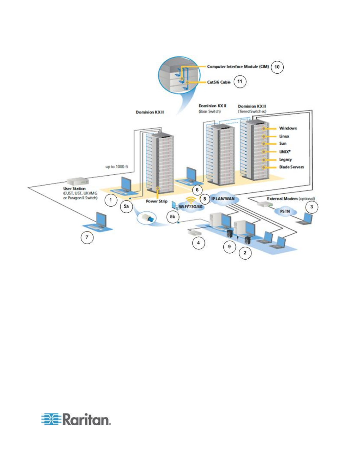
Diagram key
Local port access
Tiering
IP-based network
access
Extended local port
Modem
Mobile access via iPhone®
and iPad® using CC-SG
Virtual media
Digital audio
Smart card access at
the rack
CIMs
Remote smart card
access
Cat5/6 cable
Package Contents
Each KX II ships as a fully-configured stand-alone product in a standard
1U (2U for DKX2-864) 19" rackmount chassis. Each KX II device ships
with the following contents:
1 - KX II device
1 - KX II Quick Setup Guide
1 - Rackmount kit
2 - AC power cords
2 - Cat5 network cable
1 - Cat5 network crossover cable
1 - Set of 4 rubber feet (for desktop use)
1 - Application note
1 - Warranty card
Page 16
Chapter 1: Introduction
5
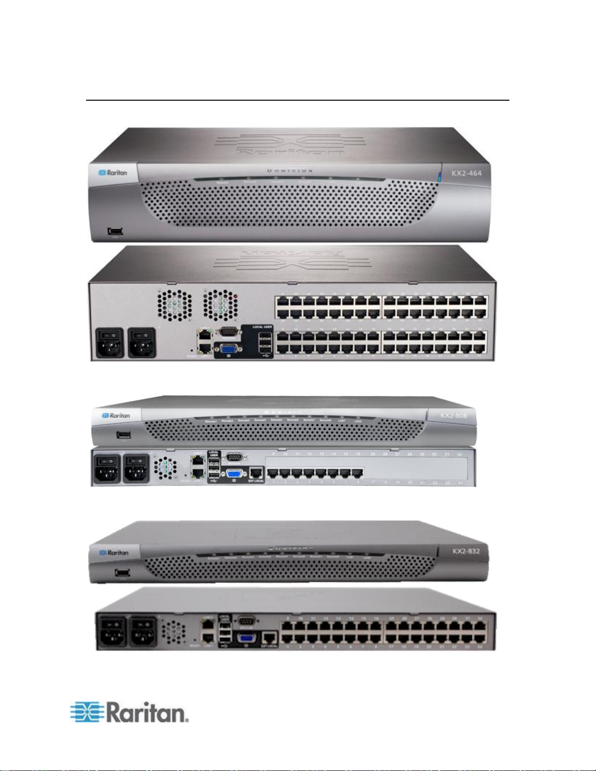
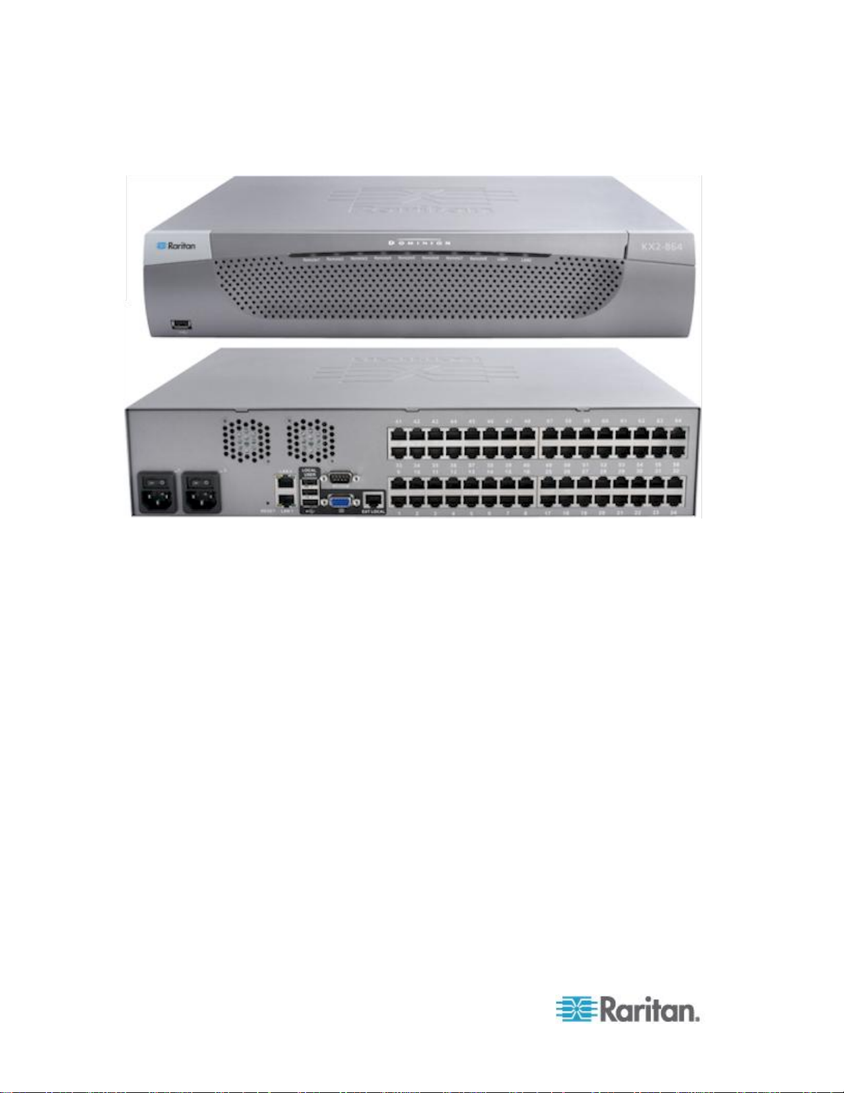
KX II Device Photos and Features
KX II
KX2-808
Page 17
Chapter 1: Introduction
6
KX2-832
KX2-864
See KX II Dimensions and Physical Specifications (on page 287) for
product specifications. See Supported Computer Interface Module
(CIMs) Specifications (on page 289) for CIM specifications and images.
Page 18

Chapter 1: Introduction
7
Product Features
Model
Remote users
Ports
KX II-864
8
64
KX II-832
8
32
KX II-808
8 8 KX II-464
4
64
KX II-432
4
32
Hardware
Integrated KVM-over-IP remote access
1U or 2U rack-mountable (brackets included)
Dual power supplies with failover; autoswitching power supply with
power failure warning
Support for tiering in which a base KX II device is used to access
multiple other tiered devices. See Configuring and Enabling
Tiering (on page 147) for more information on tiering.
Multiple user capacity (1/2/4/8 remote users; 1 local user)
UTP (Cat5/5e/6) server cabling
Dual Ethernet ports (10/100/1000 LAN) with failover
Field upgradable
Local User port for in-rack access
Keyboard/mouse ports on the KX2-808, KX2-832 and KX2-864
are USB only
One front and three back panel USB 2.0 ports for supported USB
devices
Fully concurrent with remote user access
Local graphical user interface (GUI) for administration
Extended local port provides extended reach to in-rack access on
KX2-8xx devices
Centralized access security
Integrated power control
LED indicators for dual power status, network activity, and remote
user status
Hardware Reset button
Serial port to connect to an external modem
Supported users and ports per model:
Page 19

Chapter 1: Introduction
8
Model
Remote users
Ports
KX II-416
4
16
KX II-232
2
32
KX II-216
2
16
KX II-132
1
32
KX II-116
1
16
KX II-108
1
8
Software
Virtual media support in Windows®, Mac® and Linux® environments
with D2CIM-VUSB and D2CIM-DVUSB CIMs and digital CIMs
Support for digital audio over USB
Port scanning and thumbnail view of up to 32 targets within a
configurable scan set
Absolute Mouse Synchronization with D2CIM-VUSB CIM,
D2CIM-DVUSB CIM and digital CIMs
Plug-and-Play
Web-based access and management
Intuitive graphical user interface (GUI)
Support for dual port video output
256-bit encryption of complete KVM signal, including video and
virtual media
LDAP, Active Directory®, RADIUS, or internal authentication and
authorization
DHCP or fixed IP addressing
Smart card/CAC authentication
SNMP, SNMP3 and Syslog management
IPv4 and IPv6 support
Power control associated directly with servers to prevent mistakes
Integration with Raritan's CommandCenter Secure Gateway (CC-SG)
management unit
CC Unmanage feature to remove device from CC-SG control
Support of Raritan PX1 and PX2 appliances
Page 20

Chapter 1: Introduction
9
KX II Client Applications
The following client applications can be used in the KX II:
KX II 2.2 (and later):
Virtual KVM Client (VKC)
Active KVM Client (AKC)
Multi-Platform Client (MPC)
KX II (Generation 2):
Virtual KVM Client (VKC)
Multi-Platform Client (MPC)
Java™ 1.7 is required to use the Java-based Java-based KX II Virtual
KVM Client (VKC) and Multi-Platform Client (MPC)..
Microsoft .NET® 3.5 (or later) is required to use KX II with the Microsoft
Windows®-based Active KVM Client (AKC).
KX II Help
KX II online help is considered your primary help resource. PDF versions
of help are a secondary resource.
See the KX II Release Notes for important information on the current
release before you begin using the KX II.
KVM Client help is provided as part of KX II online help.
Online help is accompanied by the KX II Quick Setup Guide, which is
included with your KX II and can be found on the Raritan Support page
of Raritan's website
(http://www.raritan.com/support/firmware-and-documentation).
Note: To use online help, Active Content must be enabled in your
browser.
Page 21

10
In This Chapter
Overview .................................................................................................. 10
Rack Mounting ......................................................................................... 10
Default Login Information ........................................................................ 12
Getting Started ........................................................................................ 12
Logging in to the KX II ............................................................................. 25
Allow Pop-Ups ......................................................................................... 26
Security Warnings and Validation Messages .......................................... 26
Installing a Certificate .............................................................................. 27
Overview
Chapter 2
Installation and Configuration
Rack Mounting
This section provides a brief overview of the installation process. Each
step is further detailed in the remaining sections of this chapter.
Before installing the KX II, configure the target server you want to access
via the KX II so you ensure optimum performance.
The KX II can be mounted in 1U (1.75", 4.4 cm) of vertical space in a
standard 19" equipment rack.
Note: The Raritan device depicted in the rack mounting diagrams is for
example purposes only and may not depict your device. The mounting
instructions are specific to your device.
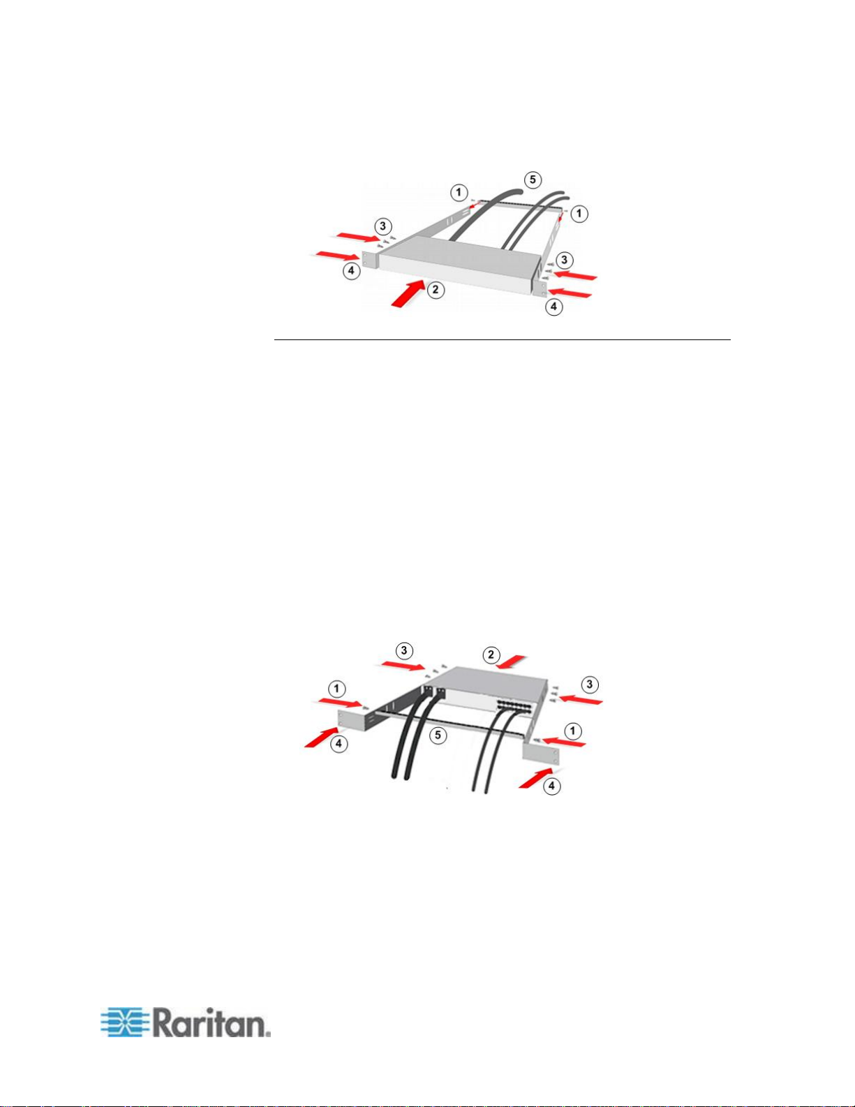
Forward Mount
The steps correspond to the numbers shown in the front rackmount
diagrams.
1. Secure the cable-support bar to the back end of the side brackets
using two of the included screws.
2. Slide the KX II between the side brackets, with its rear panel facing
the cable-support bar, until its front panel is flush with the “ears” of
the side brackets.
3. Secure the KX II to the side brackets using the remaining included
screws (three on each side).
4. Mount the entire assembly in your rack, and secure the side
brackets' ears to the rack's front rails with your own screws, bolts,
cage nuts, and so on.
Page 22
Chapter 2: Installation and Configuration
11
5. When connecting cables to the rear panel of the KX II drape them
over the cable-support bar.
Rear Mount
The steps correspond to the numbers shown in the rear rackmount
diagrams.
1. Secure the cable-support bar to the front end of the side brackets,
near the side brackets' “ears,” using two of the included screws.
2. Slide the KX II between the side brackets, with its rear panel facing
the cable-support bar, until its front panel is flush with the back
edges of the side brackets.
3. Secure the KX II to the side brackets using the remaining included
screws (three on each side).
4. Mount the entire assembly in your rack and secure the side brackets'
ears to the rack's front rails with your own screws, bolts, cage nuts,
and so on.
5. When connecting cables to the rear panel of the user station or
switch, drape them over the cable-support bar.
Page 23

Chapter 2: Installation and Configuration
12
Default Login Information
Default
Value
User name
admin
This user has administrative privileges.
Password
raritan
The first time you start the KX II, you are required to
change the default password.
IP address
192.168.0.192.
Important: For backup and business continuity purposes, it is strongly
recommended that you create a backup administrator user name and
password and keep that information in a secure location.
Getting Started
Note that the following configuration requirements apply only to the
target server, not to the computers that you remotely access the KX II.
Step 1: Configuring Network Firewall Settings
TCP Port 5000
Allow network and firewall communication on TCP Port 5000 to enable
remote access to the KX II.
Alternatively, configure the KX II to use a different TCP port, then allow
communication on that port.
TCP Port 443
Allow access to TCP Port 443 (Standard HTTPS) so you can access KX
II via a web browser.
TCP Port 80
Allow access to TCP Port 80 (Standard HTTP) to enable automatic
redirection of HTTP requests to HTTPS.
Page 24

Chapter 2: Installation and Configuration
13
Step 2: Configure the KVM Target Servers
Target Server Video Resolutions
For optimal bandwidth efficiency and video performance, KVM target
servers running graphical user interfaces such as Windows®, Linux®,
X-Windows, Solaris™, and KDE may require configuration.
The desktop background does not need to be completely solid, but
desktop backgrounds featuring photos or complex gradients might
degrade performance.
Ensure that the server video resolution and refresh rate are supported by
KX II, and that the signal is non-interlaced.
See the KX II Online Help for a list of supported target server video
resolutions.
Mouse Settings
Following are the mouse settings for various operating systems.
These settings are configured on your target operating system unless
otherwise indicated.
See the KX II Online Help for details on configuring these mouse
settings.
Windows 7 and Windows Vista Mouse Settings
Configure these mouse settings in Windows 7® and Windows
Vista®:
Configure the motion settings:
Set the mouse motion speed setting to exactly the middle speed
Disable the "Enhanced pointer precision" option
Disable animation and fade effects:
Animate controls and elements inside windows
Animate windows when minimizing and maximizing
Fade or slide menus into view
Fade or slide ToolTips into view
Fade out menu items after clicking
Page 25

Chapter 2: Installation and Configuration
14
Windows XP, Windows 2003, Windows 2008 Mouse Settings
Configure these mouse settings in Windows XP®, Windows
2003® and Windows 2008®:
Configure the Motion settings:
Set the mouse motion speed setting to exactly the middle speed
Disable the "Enhance pointer precision" option
Disable the Snap To option
Disable transition effects:
Deselect the "Use the following transition effect for menus and
tooltips" option
Windows 2000 Mouse Settings
Configure these Windows 2000® mouse settings:
Configure the Motion settings:
Set the acceleration to None
Set the mouse motion speed setting to exactly the middle speed
Disable transition effects:
Deselect the "Use the following transition effect for menus and
tooltips" option
Apple Mac Mouse Settings
Configure these Apple Mac® mouse settings:
Absolute Mouse Synchronization is required for proper mouse
synchronization on KVM target servers running a Mac® operating system.
In order for Absolute Mouse Synchronization to work, a virtual media
CIM is required. For a list of supported CIMs, see Supported Computer
Interface Module (CIMs) Specifications.
Once you have completed your KX II installation, set the Mac USB profile.
If you do not set this profile, the mouse does synch in OS X.
To do this, do one of the following:
1. Connect to the Mac target from the Raritan KVM Client.
2. Select USB Profile > Other Profiles > Mac OS-X (10.4.9 and later).
Or
Page 26

Chapter 2: Installation and Configuration
15
3. In KX II, select Device Settings > Port Configuration, then click on
the target name to open the Port page.
4. Expand 'Select USB Profiles for Port' section.
5. Select 'Mac OS-X (10.4.9) and later' from the Available box, then
click Add to add it to the Selected box.
6. Click on 'Mac OS-X (10.4.9) and later' in the Selected box. This
automatically adds it to the Preferred Profile drop-down.
7. Select 'Mac OS-X (10.4.9) and later' from the Preferred Profile
drop-down, then check the checkbox under 'Set Active Profile As
Preferred Profile'.
Click OK to apply.
Linux Mouse Settings
Configure these Linux® mouse settings:
(Standard Mouse Mode only) Set the mouse acceleration to exactly
1 and set the threshold to exactly 1. Enter the following command:
xset mouse 1 1. This should be set for execution upon login.
Sun Solaris Mouse Settings
Configure these Sun® Solaris™ mouse settings:
Set the mouse acceleration value to exactly 1 and the threshold to
exactly 1
Ensure that your video card is set to a supported resolution and that
its output is VGA, not composite sync
IBM AIX Mouse Settings
Configure these IBM AIX® mouse settings:
Go to the Style Manager, click on Mouse Settings and set Mouse
Acceleration to 1.0 and Threshold to 3.0
Page 27
Chapter 2: Installation and Configuration
16
Step 3: Connect the Equipment
A. AC Power
Connect the power supply(s):
1. Attach the included AC power cord to the KX II, and plug it into an
AC power outlet.
2. For dual-power failover protection, attach the second included AC
power cord to the KX II, and plug it into a different power source than
the first power cord.
B. Modem Port (Optional)
Please see the KX II Online Help for information on connecting
modems.
C. Network Port
The KX II provides two Ethernet ports for failover purposes - not for
load-balancing.
By default, only LAN1 is active, and the automatic failover is disabled.
Enable network failover if you want LAN2 to use the same IP address
should the KX II internal network interface or the network switch it is
connected to become unavailable.
To connect to the network:
1. Connect a standard Ethernet cable from the network port labeled
LAN1 to an Ethernet switch, hub, or router.
2. To use the optional KX II Ethernet failover capabilities:
a. Connect a standard Ethernet cable from the network port labeled
LAN2 to an Ethernet switch, hub, or router.
Page 28

Chapter 2: Installation and Configuration
17
Enable 'Automatic Failover' on the KX II Network Configuration page.
D. Local Access Port (Local PC)
For access to target servers at the rack, use the KX II Local Access port.
The Local Access port also provides a graphical user interface from the
KX II Local Console for administration and target server access.
While the Local Access port is required for installation and setup, it is
optional for subsequent use.
Note: The KX2-808, KX2-832 and KX2-864 also provide an Extended
Local port labeled EXT LOCAL on the back of the device for access to
target servers while at the rack. The Extended Local port is not required
for the initial installation and setup. It is not enabled by default and is
configured from the Local Console and the Remote Console.
To connect the local port:
Attach a multi-sync VGA monitor, mouse, and keyboard to the
respective Local User ports using USB keyboard and mouse. The
Local User and Extended Local ports are on the back panel of the
KX II.
Monitor - attach a standard multi-sync VGA monitor to the HD15
(female) video port
Keyboard - attach either a standard keyboard to the Mini-DIN6
(female) keyboard port, or a standard USB keyboard to one of the
USB Type A (female) ports
Mouse - attach either a standard mouse to the Mini-DIN6 (female)
mouse port, or a standard USB mouse to one of the USB Type A
(female) ports
E. Target Server Ports
The KX II uses standard UTP cabling (Cat5/5e/6) to connect to each
target server.
For information on the supported distances between the KX II and target
server, see Supported Target Server Connection Distance/Refresh
Rate/Video Resolution in KX II Online Help.
If you are using digital CIMs (DCIMs), review Digital CIM Target Server
Timing and Video Resolution in KX II Online Help.
To connect a target server to the KX II:
1. Use the appropriate CIM or DCIM. Attach the video connector of
your CIM/DCIM to the video port of your target server.
Page 29

Chapter 2: Installation and Configuration
18
2. Ensure that your target server's video is configured to a supported
resolution and refresh rate.
For Sun servers, ensure your target server's video card is set to
output standard VGA (H-and-V sync) and not composite sync.
3. Attach the keyboard/mouse connector of your CIM/DCIM to the
corresponding ports on your target server.
Use a DCIM if you are connecting from the target server video port to
the KX II.
4. Attach the CIM/DCIM to an available server port on the back of the
KX II using a standard, straight-through UTP (Cat5/5e/6) cable for
CIMs, or standard USB cable for DCIMs.
Note: The DCIM-USB G2 provides a small slide switch on the back of the
CIM. Move the switch to P for PC-based USB target servers. Move the
switch to S for Sun USB target servers. Power-cycle the CIM by
removing the USB connector from the target server, then plugging it back
in a few seconds later in order to apply the new switch position.
Step 4: Configure the KX II
For the following steps, you must change the default password and
assign the KX II its IP address at the Local Console.
All other steps can be performed from either the Local Console, or from
the KX II Remote Console via a supported web browser using the KX II's
default IP address.
Java™ 1.7 is required to use the Java-based Java-based KX II Virtual
KVM Client (VKC) and Multi-Platform Client (MPC)..
Microsoft .NET® 3.5 (or later) is required to use KX II with the Microsoft
Windows®-based Active KVM Client (AKC).
Change the Default Password
The first time you start the KX II, you are required to change the default
password.
To change the default password:
1. Once the unit has booted, enter the default username admin and
password raritan. Click Login.
2. Enter the old password raritan, then enter and reenter a new
password.
Passwords can be up to 64 characters in length consisting of English,
alphanumeric and special characters.
3. Click Apply. Click OK on the Confirmation page.
Page 30

Chapter 2: Installation and Configuration
19
Assign the KX II an IP Address
To assign an IP address to the KX II:
1. Choose Device Settings > Network. The Network Settings page
opens.
2. Specify a meaningful Device Name for your KX II device.
Up to 32 alphanumeric and valid special characters, no spaces
between characters.
3. Next, configure the IPv4, IPv6 and DNS settings.
Configure the IPv4 Settings
1. In the IPv4 section, enter or select the appropriate IPv4-specific
network settings:
a. Enter the IP Address if needed. The default IP address is
192.168.0.192.
b. Enter the Subnet Mask. The default subnet mask is
255.255.255.0.
c. Enter the Default Gateway if None is selected from the IP Auto
Configuration drop-down.
d. Enter the Preferred DHCP Host Name if DHCP is selected from
the IP Auto Configuration drop-down.
e. Select the IP Auto Configuration. The following options are
available:
None (Static IP) - This option requires you manually specify the
network parameters.
This is the recommended option because the KX II is an
infrastructure device, and its IP address should not change.
Select this option if you want to ensure redundant failover
capabilities should the primary Ethernet port (or the switch/router
to which it is connected) fail. If it fails, KX III fails over to the
secondary network port with the same IP address, ensuring there
is not interruption.
DHCP - Dynamic Host Configuration Protocol is used by
networked computers (clients) to obtain unique IP addresses
and other parameters from a DHCP server.
With this option, network parameters are assigned by the DHCP
server.
If DHCP is used, enter the Preferred host name (DHCP only). Up
to 63 characters.
2. Next, configure IPv6 and/or DNS settings.
Page 31

Chapter 2: Installation and Configuration
20
Configure the IPv6 Settings
1. If using IPv6, enter or select the appropriate IPv6-specific network
settings in the IPv6 section:
a. Select the IPv6 checkbox to activate the fields in the section and
enable IPv6 on the device.
b. Enter a Global/Unique IP Address. This is the IP address
assigned to the KX II.
c. Enter the Prefix Length. This is the number of bits used in the
IPv6 address.
d. Enter the Gateway IP Address.
e. Link-Local IP Address. This address is automatically assigned to
the device, and is used for neighbor discovery or when no
routers are present. Read-Only
f. Zone ID. Identifies the device the address is associated with.
Read-Only
g. Select an IP Auto Configuration option:
None (Static IP) - this option requires you manually specify the
network parameters.
This is the recommended option because the KX II is an
infrastructure device, and its IP address should not change.
Select this option if you want to ensure redundant failover
capabilities should the primary Ethernet port (or the switch/router
to which it is connected) fail. If it fails, KX III switches to the
secondary network port with the same IP address, ensuring their
is no interruption.
If None is selected, the following Network Basic Settings fields
are enabled: Global/Unique IP Address, Prefix Length, and
Gateway IP Address allowing you to manually set the IP
configuration.
Router Discovery - use this option to automatically assign IPv6
addresses that have Global or Unique Local significance beyond
that of the Link Local, which only applies to a directly connected
subnet.
2. Next, configure DNS settings.
Configure the DNS Settings
1. Select Obtain DNS Server Address Automatically if DHCP is
selected and Obtain DNS Server Address is enabled. When Obtain
DNS Server Address Automatically, the DNS information provided by
the DHCP server will be used.
Page 32

Chapter 2: Installation and Configuration
21
2. If Use the Following DNS Server Addresses is selected, whether or
not DHCP is selected, the addresses entered in this section is used
to connect to the DNS server.
Enter the following information if the Following DNS Server
Addresses is selected. These addresses are the primary and
secondary DNS addresses used if the primary DNS server
connection is lost due to an outage.
a. Primary DNS Server IP Address
b. Secondary DNS Server IP Address
3. When finished, click OK.
Your KX II device is now network accessible.
Name Your Target Servers
To name the target servers:
1. Connect all of the target servers if you have not already done so.
2. Select Device Settings > Port Configuration, then click the Port
Name of the target server you want to name.
3. Enter a name for the server up to 32 alphanumeric and special
characters. Click OK.
Specify Power Supply Autodetection
The KX II provides dual power supplies.
When both power supplies are used, the KX II automatically detects
them and notifies you of their status.
Additionally, both the Powerln1 and Powerln2 Auto Detect checkboxes
are automatically selected on the Power Supply Setup page.
If you are using only one power supply, you can enable automatic
detection for only the power supply in use.
To enable automatic detection for the power supply in use:
1. Choose Device Settings > Power Supply Setup. The Power Supply
Setup page opens.
2. If you are plugging power input into power supply number one
(left-most power supply at the back of the device), select the
Powerln1 Auto Detect option.
3. If you are plugging power input into power supply number two
(right-most power supply at the back of the device), select the
Powerln2 Auto Detect option. Click OK.
Page 33

Chapter 2: Installation and Configuration
22
If either of these checkboxes is selected and only power input is
connected, the power LED on the front of the device is Red.
Configure Date/Time Settings (Optional)
Optionally, configure the date and time settings.
The date and time settings impact SSL certificate validation if LDAPS is
enabled.
Use the Date/Time Settings page to specify the date and time for the KX
II. There are two ways to do this:
Manually set the date and time.
Synchronize the date and time with a Network Time Protocol (NTP)
server.
To set the date and time:
1. Choose Device Settings > Date/Time. The Date/Time Settings page
opens.
2. Choose your time zone from the Time Zone drop-down list.
3. Adjust for daylight savings time by checking the "Adjust for daylight
savings time" checkbox.
4. Choose the method to use to set the date and time:
User Specified Time - use this option to input the date and time
manually. For the User Specified Time option, enter the date and
time. For the time, use the hh:mm format (using a 24-hour clock).
Synchronize with NTP Server - use this option to synchronize the
date and time with the Network Time Protocol (NTP) Server.
5. For the Synchronize with NTP Server option:
a. Enter the IP address of the Primary Time server.
b. Enter the IP address of the Secondary Time server. Optional
Note: If DHCP is selected for the Network Settings on the Network
page, the NTP server IP address is automatically retrieved from the
DHCP server by default. Manually enter the NTP server IP address
by selecting the Override DHCP checkbox.
6. Click OK.
Page 34

Chapter 2: Installation and Configuration
23
Step 5: Launching the KX II Remote Console
Log in to your KX II Remote Console from any workstation with network
connectivity that has Microsoft .NET® and/or Java Runtime Environment™
installed.
To launch the KX II Remote Console:
1. Launch a supported web browser.
2. Enter either:
The URL - http://IP-ADDRESS to use the Java-based Virtual
KVM Client
Or
http://IP-ADDRESS/akc for the Microsoft .NET-based Active KVM
Client
IP-ADDRESS is the IP address assigned to your KX II
You can also use HTTPS, or the DNS name of the KX II assigned by
your administrator (if applicable).
3. You are always redirected to the IP address from HTTP to HTTPS.
4. Enter your username and password. Click Login.
Access and Control Target Servers Remotely
The KX II Port Access page provides a list of all KX II ports, as well as
the connected target servers, their status, and availability.
Accessing a Target Server
To access a target server:
1. On the KX II Port Access page, click the Port Name of the target you
want to access.
The Port Action Menu is displayed.
2. Choose Connect from the Port Action menu.
A KVM window opens with a connection to the target.
Switching between Target Servers
To switch between KVM target servers:
1. While already using a target server, access the KX II Port Access
page.
2. Click the port name of the target you want to access. The Port Action
menu appears.
Page 35

Chapter 2: Installation and Configuration
24
3. Choose Switch From in the Port Action menu. The new target server
you selected is displayed.
Disconnecting a Target Server
To disconnect a target server:
On the Port Access page, click the port name of the target you want
to disconnect from, then click Disconnect on Port Action menu when
it appears.
Step 6: Configuring the Keyboard Language (Optional)
Note: This step is not required if you are using the US/International
language keyboard.
If you are using a non-US language, the keyboard must be configured for
the appropriate language.
Additionally, the keyboard language for the client machine and the KVM
target servers must match.
Consult your operating system documentation for additional information
about changing the keyboard layout.
Changing the Keyboard Layout Code (Sun Targets)
Use this procedure if you are using a DCIM-SUSB and want to change
the keyboard layout to another language.
To change the keyboard layout code (DCIM-SUSB only):
1. Open a Text Editor window on the Sun™ workstation.
2. Check that the Num Lock key is active. then press the left Ctrl key
and the Del key on your keyboard, or select the option "set CIM
keyboard/Mouse options" from the keyboard menu.
The Caps Lock light starts to blink, indicating that the CIM is in
Layout Code Change mode.
The text window displays: Raritan Computer, Inc. Current
keyboard layout code = 22h (US5 UNIX).
3. Type the layout code desired (for example, 31 for the Japanese
keyboard). Press Enter.
4. Shut down the device and power on once again. The DCIM-SUSB
performs a reset (power cycle).
5. Verify that the characters are correct.
Page 36

Chapter 2: Installation and Configuration
25
Step 7: Configure Tiering (Optional)
The optional tiering feature allows you to use a KX II as your base device,
then connect additional KX II's to it as tiered devices.
You can then access servers and PX PDUs through the base both locally
and remotely. See the Device Management (on page 141) section of
the KX II Help for more information on this feature.
To enable tiering:
1. From the base KX II tier device, select Device Settings > Device
Services to open the Device Service Settings page.
2. Select Enable Tiering as Base.
3. In the Base Secret field, enter the secret shared between the base
and the tiered devices. This secret is required for the tiered devices
to authenticate the base device. Enter the same secret word for the
tiered device. Click OK.
4. Enable the tiered devices. From the tiered device, choose Device
Settings > Local Port Settings.
5. In the Enable Local Ports section of the page, select Enable Local
Port Device Tiering.
6. In the Tier Secret field, enter the same secret word you entered for
the base device on the Device Settings page. Click OK.
Logging in to the KX II
Log in to your KX II Remote Console from any workstation with network
connectivity. Java™ 1.7 is required to use the Java-based Java-based
Virtual KVM Client (VKC) and Multi-Platform Client (MPC). Alternatively,
Microsoft .NET® 3.5 (or later) is required to use KX II with the Microsoft
Windows®-based Active KVM Client (AKC).
Logging in and using KX II requires you to allow pop-ups.
For information on security warnings and validation messages, and steps
to reduce or eliminate them, see Security Warnings and Validation
Messages (on page 26).
To log in to the KX II:
1. Launch a supported web browser.
2. Enter either:
The URL - http://IP-ADDRESS to use the Java-based Virtual
KVM Client
Or
Page 37

Chapter 2: Installation and Configuration
26
http://IP-ADDRESS/akc for the Microsoft .NET-based Active KVM
Client
IP-ADDRESS is the IP address assigned to your KX II
You can also use HTTPS, or the DNS name of the KX II assigned by
your administrator (if applicable).
You are always redirected to the IP address from HTTP to HTTPS.
3. Enter your username and password, then click Login.
4. Accept the user agreement (if applicable).
5. If security warnings appear, accept and/or allow access.
Allow Pop-Ups
Regardless of the browser used, you must allow pop-ups from the
device's IP address to launch the KX II Remote Console.
Security Warnings and Validation Messages
When logging in to KX II, security warnings and application validation
message may appear.
These include:
Java™ security warnings and requests to validate KX II. See Java
Validation and Access Warning (on page 26), and Installing a
Certificate (on page 27)
Additional security warnings based on your browser and security
settings. See Additional Security Warnings (on page 27)
Java Validation and Access Warning
When logging in to KX II, Java™ 1.7 prompts you to validate KX II, and to
allow access to the application.
Raritan recommends installing an SSL certificate in each KX II device in
order to reduce Java warnings, and enhance security. See SSL
Certificates (on page 234)
Page 38

Chapter 2: Installation and Configuration
27
Additional Security Warnings
Even after an SSL certificate is installed in the KX II, depending on your
browser and security settings, additional security warnings may be
displayed when you log in to KX II.
It is necessary to accept these warnings to launch the KX II Remote
Console.
Reduce the number of warning messages during subsequent log ins by
checking the following options on the security and certificate warning
messages:
In the future, do not show this warning
Always trust content from this publisher
Installing a Certificate
You may be prompted by the browser to accept and validate the KX II's
SSL certificate.
Depending on your browser and security settings, additional security
warnings may be displayed when you log in to KX II.
It is necessary to accept these warnings to launch the KX II Remote
Console. For more information, see Security Warnings and Validation
Messages (on page 26).
Two sample methods on how to install an SSL Certificate in the browser
are provided here, both using Microsoft Internet Explorer 8® and
Windows 7®.
Specific methods and steps depend on your browser and operating
system. See your browser and operating system help for details.
Page 39

Chapter 2: Installation and Configuration
28
Example 1: Import the Certificate into the Browser
Steps
Open an IE browser, then log in to KX II.
Click More Information on the first Java™ security warning.
Click View Certificate Details on the More Information dialog. You are prompted to
install the certificate. Follow the wizard steps.
Note: If you are not prompted by the browser, manually select Tools > Internet
Options to open the Internet Options dialog.
In this example, you import the Certificate into the browser.
Page 40

Chapter 2: Installation and Configuration
29
Steps
Click the Content tab.
Click Certificates.
The Certificate Import Wizard opens and walks you through each step.
File to Import - Browse to locate the Certificate
Certificate Store - Select the location to store the Certificate
Click Finish on the last step of the Wizard.
The Certificate is imported. Close the success message.
Click OK on the Internet Options dialog to apply the changes, then close and reopen
the browser.
Page 41

Chapter 2: Installation and Configuration
30
Example 2: Add the KX II to Trusted Sites and Import the Certificate
Steps
Open an IE browser, then select Tools > Internet Options to open the Internet Options
dialog
Click the Security tab.
Click on Trusted Sites.
Disable Protected Mode, and accept any warnings.
Click Sites to open the Trusted Sites dialog.
Enter the KX II URL, then click Add.
Deselect server verification for the zone (if applicable).
Click Close.
In this example, the KX II's URL is added as a Trusted Site, and the Self
Signed Certificate is added as part of the process.
Page 42

Chapter 2: Installation and Configuration
31
Steps
Click OK on the Internet Options dialog to apply the changes, then close and reopen
the browser.
Next, import the Certificate.
Steps
Open an IE browser, then log in to KX II.
Click More Information on the first Java™ security warning.
Click View Certificate Details on the More Information dialog. You are prompted to
install the certificate. Follow the wizard steps.
For details see, Example 1: Import the Certificate into the Browser (on page 28)
Page 43

32
In This Chapter
KX II Interfaces ........................................................................................ 32
KX II Local Console Interface: KX II Devices .......................................... 33
KX II Remote Console Interface .............................................................. 33
Proxy Server Configuration for Use with MPC, VKC and AKC ............... 50
Virtual KVM Client (VKC) and Active KVM Client (AKC) ......................... 52
Multi-Platform Client (MPC) ..................................................................... 94
KX II Interfaces
User interface
Local
access
Admin
Remote
access
Admin
KX II Local Console
KX II Remote Console
Virtual KVM Client (VKC)
Multi-Platform Client
(MPC)
Active KVM Client (AKC)
Chapter 3
Working with Target Servers
There are several user interfaces in the KX II, providing you with easy
access anytime, anywhere to targets.
These include the KX II Local Console, the KX II Remote Console, the
Virtual KVM Client (VKC), the Active KVM Client (AKC), and the
Multi-Platform Client (MPC).
The following table identifies these interfaces and their use for target
server access and administration locally and remotely:
The following sections of the help contain information about using
specific interfaces to access the KX II and manage targets:
Local Console
Remote Console
Virtual KVM Client
Multi-Platform Client
Page 44

Chapter 3: Working with Target Servers
33
KX II Local Console Interface: KX II Devices
When you are located at the server rack, the KX II provides standard
KVM management and administration via the KX II Local Console. The
KX II Local Console provides a direct KVM (analog) connection to your
connected servers; the performance is exactly as if you were directly
connected to the server's keyboard, mouse, and video ports.
There are many similarities among the KX II Local Console and the KX II
Remote Console graphical user interfaces. Where there are differences,
they are noted in the help.
The KX II Local Console Factory Reset option is available in the KX II
Local Console but not the KX II Remote Console.
KX II Remote Console Interface
The KX II Remote Console is a browser-based graphical user interface
that allows you to log in to KVM target servers and serial targets
connected to the KX II and to remotely administer the KX II.
The KX II Remote Console provides a digital connection to your
connected KVM target servers. When you log into a KVM target server
using the KX II Remote Console, a Virtual KVM Client window opens.
There are many similarities among the KX II Local Console and the KX II
Remote Console graphical user interfaces, and where there are
differences, they are noted in the user manual. The following options are
available in the KX II Remote Console but not the KX II Local Console:
Virtual Media
Favorites
Backup/Restore
Firmware Upgrade
SSL Certificates
Audio
Page 45

Chapter 3: Working with Target Servers
34
KX II Interface
Both the KX II Remote Console and the KX II Local Console interfaces
provide a web-based interface for device configuration and
administration, as well as target server list and selection. The options are
organized into various tabs.
After a successful login, the Port Access page opens listing all ports
along with their status and availability. Four tabs are provided on the
page allowing you to view by port, view by group or view by search. You
can sort by Port Number, Port Name, Status (Up and Down), and
Availability (Idle, Connected, Busy, Unavailable, and Connecting) by
clicking on the column heading. See Port Access Page (Remote
Console Display) (on page 38) for more information.
Use the Set Scan tab to scan for up to 32 targets that are connected to
the KX II. See Scanning Ports (on page 47).
Page 46

Chapter 3: Working with Target Servers
35
Left Panel
Information
Description
When displayed?
Time & Session
The date and time the
current session started
Always
User
Username
Always
State
The current state of the
application, either idle or
active. If idle, the
application tracks and
displays the time the
session has been idle.
Always
Your IP
The IP address used to
access the KX II
Always
Last Login
The last login date and
time
Always
Under CC-SG
Management
The IP address of the
CC-SG device managing
the KX II
When the KX II is being
managed by CC-SG
Device Information
Information specific to the
KX II you are using
Always
Device Name
Name assigned to the
device
Always
IP Address
The IP address of the KX
II
Always
Firmware
Current version of
firmware
Always
Device Model
Model of the KX II
Always
Serial number
Serial number of the KX II
Always
Network
The name assigned to
the current network
Always
PowerIn1
Status of the power 1
outlet connection. Either
on or off, or Auto-detect
off
Always
The left panel of the KX II interface contains the following information.
Note that some information is conditional - meaning it is displayed based
on your role, features being used and so on. Conditional information is
noted here.
Page 47

Chapter 3: Working with Target Servers
36
Information
Description
When displayed?
PowerIn2
Status of the power 2
outlet connection. Either
on or off, or Auto-detect
off
Always
Configured As
Base or Configured
As Tiered
If you are using a tiering
configuration, this
indicates if the KX II you
are accessing is the base
device or a tiered device.
When the KX II is part of
a tiered configuration
Port States
The statuses of the ports
being used by the KX II
Always
Connect Users
The users, identified by
their username and IP
address, who are
currently connected to the
KX II
Always
Online Help
Links to online help
Always
FIPS Mode
FIPS Mode: EnabledSSL
Certificate: FIPS Mode
Compliant
When FIPS is enabled
Favorite Devices
See Managing Favorites
(on page 43)
When enabled
The left panel can be collapsed in order to increase the display area of
the page.
To collapse the left panel:
Click on the blue, left-facing arrow located approximately halfway
down the left side of the panel. Once the panel is collapsed, click the
blue arrow again to expand it.
Page 48

Chapter 3: Working with Target Servers
37
KX II Console Navigation
The KX II Console interfaces provide many methods for navigation and
making your selections.
To select an option (use any of the following):
Click on a tab. A page of available options appears.
Hover over a tab and select the appropriate option from the menu.
Click the option directly from the menu hierarchy displayed
(breadcrumbs).
To scroll through pages longer than the screen:
Use Page Up and Page Down keys on your keyboard.
Use the scroll bar on the right.
Page 49

Chapter 3: Working with Target Servers
38
Port Access Page (Remote Console Display)
After successfully logging on to the KX II remote console, the View by
Port tab on the Port Access page appears. This page lists all of the KX II
ports, and the target servers, port groups, and blade chassis that are
connected to those ports.
The information is sorted by Port Number by default, but you can change
the display to sort on any of the available columns by clicking on a
column header. To increase or decrease the number of rows displayed
on a tab at one time, enter the number of row in the Rows per Page field
and click Set.
The following information for each port is contained on this page:
Port Number - Numbered from 1 to the total number of ports
available for the KX II device.
Note: Ports connected to power strips are not listed, resulting in gaps
in the Port Number sequence.
Port Name - The name of the KX II port. Initially, this is set to
Dominion-KX2-Port# but you can change the name to something
more descriptive. When you click a Port Name link, the Port Action
Menu appears.
Note: Do not use apostrophes for the Port (CIM) Name.
Type - The type of server or CIM/DCIM.
For blade chassis, the type can be Blade Chassis, Blade,
BladeChassisAdmin, and BladeChassisURL.
Dual video port groups appear on the Port Access page as Dual Port
types.
The primary and secondary ports that are a part of the port group
appear on the Port Access page as Dual Port(P) and Dual Port(S),
respectively. For example, if the CIM type is DCIM, "DCIM Dual Port
(P)" is displayed.
Page 50

Chapter 3: Working with Target Servers
39
Status - The status of the servers - either up or down.
To connect to an available target server or dual monitor target
server:
1. Click on the port name. The Port Action menu opens.
2. Click Connect. Once you are connected to a target or dual monitor
target server, click on the port group name and then click Disconnect
to disconnect.
See Port Action Menu (on page 41) for details on additional available
menu options.
Page 51

Chapter 3: Working with Target Servers
40
View by Group Tab
The View by Group tab displays blade chassis, 'standard' port groups,
and dual video port groups. Click the Expand Arrow icon next to a
group to view the ports assigned to the port group.
See Device Management (on page 141) for information on creating
each of these types of port groups.
View by Search Tab
The View by Search tab allows you to search by port name. The search
feature supports the use of an asterisk (*) as a wildcard, and full and
partial names.
Set Scan Tab
The port scanning feature is accessed from the Set Scan tab on the Port
Access page. The feature allows you to define a set of targets to be
scanned. Thumbnail views of the scanned targets are also available.
Select a thumbnail to open that target in its Virtual KVM Client window.
See See Scanning Ports - Remote Console for more information.
Tiered Devices - Port Access Page
If you are using a tiered configuration in which a base KX II device is
used to access multiple other tiered devices, the tiered devices are
viewed on the Port Access page by clicking on the Expand Arrow icon
to the left of the tier device name. See Configuring and Enabling
Tiering (on page 147) for more information on tiering.
Page 52

Chapter 3: Working with Target Servers
41
Blade Chassis - Port Access Page
The blade chassis is displayed in an expandable, hierarchical list on the
Port Access page, with the blade chassis at the root of the hierarchy and
the individual blades labeled and displayed below the root. Use the
Expand Arrow icon next to the root chassis to display the individual
blades.
Note: To view the blade chassis in a hierarchal order, blade-chassis
subtypes must be configured for the blade server chassis.
Dual Port Video Groups - Port Access Page
Dual video port groups appear on the Port Access page as Dual Port
types.
The primary and secondary ports that are a part of the port group appear
on the Port Access page as Dual Port(P) and Dual Port(S), respectively.
For example, if the CIM type is DCIM, "DCIM Dual Port (P)" is displayed.
When you access a dual port video group from the remote client, you
connect to the primary port, which opens a KVM connection window to
both the primary and secondary ports of the dual port group.
Note: The dual video primary port is defined when the port group is
created.
Note: Two KVM channels are required to remotely connect to the dual
video port group by clicking primary port. If two channels are not
available, the Connect link is not displayed.
Note: The Action menu is not displayed when you click on a secondary
port in a dual video port group.
Note: You cannot connect to the primary port and secondary port at the
same time from the Local Port.
Port Action Menu
When you click a Port Name in the Port Access list, the Port Action menu
appears.
Choose the desired menu option for that port to execute it. Note that only
currently available options, depending on the port's status and availability,
are listed in the Port Action menu.
Connect - Creates a new connection to the target server.
For the KX II Remote Console, a new Virtual KVM Client page
appears.
For the KX II Local Console, the display switches to the target server,
and switches away from the local user interface.
Page 53

Chapter 3: Working with Target Servers
42
On the local port, the KX II Local Console interface must be visible in
order to perform the switch.
Hot key switching is also available from the local port.
Note: This option is not available from the KX II Remote Console for
an available port if all connections are busy.
Switch From - Switches from an existing connection to the selected
port (KVM target server).
This menu item is available only for KVM targets, and only when a
Virtual KVM Client is opened.
Note: This menu item is not available on the KX II Local Console.
Disconnect - Disconnects this port and closes the Virtual KVM Client
page for this target server.
This menu item is available only when the port status is up and
connected, or up and busy.
Note: This menu item is not available on the KX II Local Console.
The only way to disconnect from the switched target in the Local
Console is to use the hot key.
Power On - Powers on the target server through the associated
outlet.
This option is visible only when there are one or more power
associations to the target, and when the user has permission to
operate this service.
Power Off - Powers off the target server through the associated
outlets.
This option is visible only when there are one or more power
associations to the target, when the target power is on (port status is
up), and when user has permission to operate this service.
Power Cycle - Power cycles the target server through the associated
outlets.
This option is visible only when there are one or more power
associations to the target, and when the user has permission to
operate this service.
Page 54

Chapter 3: Working with Target Servers
43
Managing Favorites
A Favorites feature is provided so you can organize and quickly access
the devices you use frequently.
The Favorite Devices section is located in the lower left side (sidebar) of
the Port Access page and provides the ability to:
Create and manage a list of favorite devices
Quickly access frequently-used devices
List your favorites either by Device Name, IP Address, or DNS
hostname
Discover KX II devices on its subnet (before and after login)
Retrieve discovered KX II devices from the connected Dominion
device (after login)
Page 55

Chapter 3: Working with Target Servers
44
Enable Favorites
Click Enable in the Favorite Devices section of the left panel of the
KX II interface.
Once enabled, the Enable button becomes a Disable button.
Page 56

Chapter 3: Working with Target Servers
45
Access and Display Favorites
To access a favorite KX II device:
Click the device name (listed beneath Favorite Devices). A new
browser opens to that device.
To display favorites by name:
Click Display by Name.
To display favorites by IP Address:
Click Display by IP.
To display favorites by the host name:
Click Display by Host Name.
Discovering Devices on the Local Subnet
This option discovers the devices on your local subnet, which is the
subnet where the KX II Remote Console is running. These devices can
be accessed directly from this page or you can add them to your list of
favorites. See Favorites List Page.
To discover devices on the local subnet:
1. Choose Manage > Discover Devices - Local Subnet. The Discover
Devices - Local Subnet page appears.
2. Choose the appropriate discovery port:
Page 57

Chapter 3: Working with Target Servers
46
To use the default discovery port, select the Use Default Port
5000 checkbox.
To use a different discovery port:
a. Deselect the Use Default Port 5000 checkbox.
b. Type the port number in the Discover on Port field.
c. Click Save.
3. Click Refresh. The list of devices on the local subnet is refreshed.
To add devices to your Favorites List:
1. Select the checkbox next to the device name/IP address.
2. Click Add.
To access a discovered device:
Click the device name or IP address for that device. A new browser
opens to that device.
Discovering Devices on the KX II Subnet
This option discovers devices on the device subnet, which is the subnet
of the KX II device IP address itself. You can access these devices
directly from this the Subnet page or add them to your list of favorites.
See Favorites List Page.
This feature allows multiple KX II devices to interoperate and scale
automatically. The KX II Remote Console automatically discovers the KX
II devices, and any other Raritan device, in the subnet of the KX II.
To discover devices on the device subnet:
1. Choose Manage > Discover Devices - KX II Subnet. The Discover
Devices - KX II Subnet page appears.
2. Click Refresh. The list of devices on the local subnet is refreshed.
To add devices to your Favorites List:
1. Select the checkbox next to the device name/IP address.
2. Click Add.
To access a discovered device:
Click the device name or IP address for that device. A new browser
opens to that device.
Page 58

Chapter 3: Working with Target Servers
47
Scanning Ports
The KX II provides the port scanning feature to search for selected
targets, and display them in a slide show view, allowing you to monitor
up to 32 targets at one time.
You can connect to targets or focus on a specific target as needed.
Scans can include standard targets, blade servers, tiered Dominion
devices, and KVM switch ports.
Configure scan settings from either the Virtual KVM Client (VKC) or
Active KVM Client (AKC).
Note: For dual video port groups, the primary port is included in a port
scan, but the secondary port is not included when connecting from a
remote client. Both ports can be included in the scan from the Local Port.
Dual video port groups are supported by the KX II 2.5.0 (and later).
Note: Scanning for tiered devices is not supported by the Multi-Platform
Client (MPC).
When you start a scan, the Port Scan window opens.
As each target is found, it is displayed as a thumbnail in a slide show.
The slide show scrolls through the target thumbnails based on the
default interval of 10 seconds or according to the interval you specify.
As the scan scrolls through the targets, the target that is the focus of the
slide show displays in the center of the page.
The name of the target is displayed below its thumbnail and in the task
bar at the bottom of the window.
If a target is busy, a blank screen is displayed instead of the target server
access page.
The status of each target is indicated by green, yellow and red lights that
are displayed below the target thumbnail and, as the target is the focus
of the rotation, in the task bar.
Lights for each target are gray until they are the focus of the slide show.
The status lights indicate the following:
Green - the target is up/idle or up/connected
Yellow - the target is down but connected
Red - the target is down/idle, busy, or otherwise not accessible
This feature is available from the Local Port, Virtual KVM Client (VKC),
Active KVM Client (AKC) and Multi-Platform Client (MPC).
Page 59

Chapter 3: Working with Target Servers
48
Note: MPC uses a different method for initiating a scan than the other
Raritan clients. See Set Scan Group in the KVM and Serial Client
Guide for details. The scan results and scan options differ between the
Remote Console and the Local Console. See Scanning Ports - Local
Console (on page 269).
To scan for targets:
1. Click the Set Scan tab on the Port Access page.
2. Select the targets you want to include in the scan by selecting the
checkbox to the left of each target, or select the checkbox at the top
of the target column to select all targets.
3. Leave the Up Only checkbox selected if you only want targets that
are up to be included in the scan. Deselect this checkbox if you want
to include all targets, whether up or down.
4. Click Scan to begin the scan.
As each target is scanned, it is displayed in slide show view on the
page.
5. Click Options > Pause to pause the slide show and stop it from
moving between targets, click Options > Resume to resume the slide
show.
6. Click on a target thumbnail to scan it next.
7. Connect to a target by double clicking on its thumbnail.
Page 60

Chapter 3: Working with Target Servers
49
Using Scan Port Options
Following are options available to you while scanning targets.
With the exception of the Expand/Collapse icon, all of these options are
selected from the Options menu in the upper left of the Port Scan viewer.
The options will return to their defaults when you close the window.
Note: Configure scan settings such as the display interval from either the
Virtual KVM Client (VKC) or Active KVM Client (AKC). See Configuring
Port Scan Settings in VKC and AKC
Hide or View Thumbnails
Use the Expand/Collapse icon at the upper left of the window to
hide or view thumbnails. Expanded is the default view.
Pause the Thumbnail Slide Show
Pause thumbnails from rotating between one target and the next by
selecting Options > Pause. Rotating thumbnails is the default setting.
Resume the Thumbnail Slide Show
Resume the thumbnail rotation by selecting Options > Resume.
Size the Thumbnails in the Port Scan Viewer
Enlarge the size of the thumbnails by selecting Options > Size >
360x240.
Minimize the size of the thumbnails by selection Options > Size >
160x120. This is the default thumbnail size.
Change the Orientation of the Port Scan Viewer
View thumbnails along the bottom of the Port Scan viewer by
selecting Options > Split Orientation > Horizontal.
View thumbnails along the right of the Port Scan viewer by selecting
Options > Split Orientation > Vertical. This is the default view.
Page 61

Chapter 3: Working with Target Servers
50
Logging Out
To quit the KX II:
Click Logout in the upper right-hand corner of the page.
Note: Logging out also closes any open Virtual KVM Client and serial
client sessions.
Proxy Server Configuration for Use with MPC, VKC and AKC
When the use of a Proxy Server is required, a SOCKS proxy must also
be provided and configured on the remote client PC.
Note: If the installed proxy server is only capable of the HTTP proxy
protocol, you cannot connect.
To configure the SOCKS proxy:
1. On the client, select Control Panel > Internet Options.
a. On the Connections tab, click 'LAN settings'. The Local Area
Network (LAN) Settings dialog opens.
b. Select 'Use a proxy server for your LAN'.
c. Click Advanced. The Proxy Settings dialog opens.
d. Configure the proxy servers for all protocols. IMPORTANT: Do not
select 'Use the same proxy server for all protocols'.
Note: The default port for a SOCKS proxy (1080) is different from
HTTP proxy (3128).
2. Click OK at each dialog to apply the settings.
3. Next, configure the proxies for Java™ applets by selecting Control
Panel > Java.
Page 62

Chapter 3: Working with Target Servers
51
e. On the General tab, click Network Settings. The Network Settings
dialog opens.
f. Select Use Proxy Server.
g. Click Advanced. The Advanced Network Settings dialog opens.
h. Configure the proxy servers for all protocols. IMPORTANT: Do not
select 'Use the same proxy server for all protocols'.
Note: The default port for a SOCKS proxy (1080) is different from
HTTP proxy (3128).
4. If you are using standalone MPC, you must also do the following:
i. Open the start.bat file in MPC directory with a text editor.
j. Insert the following parameters to the command line. Add them
before "-classpath": -DsocksProxyHost=<socks proxy ip addr>
-DsocksProxyPort=<socks proxy port>
The parameters should look as follows:
start javaw -Xmn128M -Xmx512M -XX:MaxHeapFreeRatio=70
-XX:MinHeapFreeRatio=50 -Dsun.java2d.noddraw=true
-DsocksProxyHost=192.168.99.99 -DsocksProxyPort=1080
-classpath .\sdeploy.jar;.\sFoxtrot.jar;.\jaws.jar;.\sMpc.jar
com.raritan.rrc.ui.RRCApplication %1
Page 63

Chapter 3: Working with Target Servers
52
Virtual KVM Client (VKC) and Active KVM Client (AKC)
Overview
Whenever you access a target server from the Port Access page of KX II
the Remote Console, a Virtual KVM Client (VKC) window opens.
There is one Virtual KVM Client for each target server connected.
Virtual KVM Client windows can be minimized, maximized, and moved
around your computer desktop.
IMPORTANT: Refreshing your browser closes the Virtual KVM
Client connection, so exercise caution.
Virtual KVM Client Java Requirements
Java™ 1.7 is required to use the Java-based Virtual VKM Client (VKC).
Page 64

Chapter 3: Working with Target Servers
53
Virtual KVM Client (VKC) and Active KVM Client (AKC) Shared
Features
The Virtual KVM Client (VKC) and Active KVM Client (AKC) are
interfaces used to access remote targets.
VKC and AKC share similar features with the exception of the following:
Minimum system requirements
Supported operating systems and browsers
Keyboard macros created in AKC cannot be used in VKC
Direct port access configuration (see Enabling Direct Port Access
via URL)
AKC server certification validation configuration (see Prerequisites
for Using AKC (on page 93))
Connect to a Target Server
Once you have logged on to the KX II Remote Console, access target
servers via the Virtual KVM Client (VKC) or Active KVM Client (AKC).
To connect to an available server:
1. On the Port Access page, click on the port name of the target server
you want to connect to. The Port Action menu opens.
2. Click Connect.
See Port Action Menu for details on additional available menu options.
Page 65

Chapter 3: Working with Target Servers
54
Connection Properties
Dynamic video compression algorithms maintain KVM console usability
under varying bandwidth constraints.
The devices optimize KVM output not only for LAN use, but also for WAN
use.
These devices can also control color depth and limit video output,
offering an optimal balance between video quality and system
responsiveness for any bandwidth.
The parameters in the Properties dialog can be optimized to suit your
needs for different operating environments. Connection properties are
saved across subsequent connections to generation 2 devices once they
are set and saved.
To set the connection properties:
1. Choose Connection > Properties or click the Connection Properties
button in the toolbar. The Properties dialog appears.
2. Choose the Connection Speed from the drop-down list. The device
can automatically detect available bandwidth and not limit bandwidth
use. However, you can also adjust this usage according to
bandwidth limitations.
Auto
1G Ethernet
100 Mb Ethernet
10 Mb Ethernet
1.5 Mb (MAX DSL/T1)
1 Mb (Fast DSL/T1)
512 Kb (Medium DSL/T1)
384 Kb (Slow DSL/T1)
256 Kb (Cable)
128 Kb (Dual ISDN)
56 kb (ISP Modem)
33 kb (Fast Modem)
24 kb (Slow Modem)
Note that these settings are an optimization for specific conditions
rather than an exact speed. The client and server always attempt to
deliver video as quickly as possible on the network regardless of the
current network speed and encoding setting. But the system will be
most responsive when the settings match the real world environment.
Page 66

Chapter 3: Working with Target Servers
55
3. Choose the Color Depth from the drop-down list. The device can
dynamically adapt the color depth transmitted to remote users in
order to maximize usability in all bandwidths.
15-bit RGB Color
8-bit RGB Color
4-bit Color
4-bit Gray
3-bit Gray
2-bit Gray
Black and White
Important: For most administrative tasks (server monitoring,
reconfiguring, and so on), the full 24-bit or 32-bit color spectrum
made available by most modern video graphics cards is not
necessary. Attempting to transmit such high color depths wastes
network bandwidth.
4. Use the slider to select the desired level of Smoothing (15-bit color
mode only). The level of smoothing determines how aggressively to
blend screen regions with small color variation into a single smooth
color. Smoothing improves the appearance of target video by
reducing displayed video noise.
5. Click OK to set these properties.
Page 67

Chapter 3: Working with Target Servers
56
Connection Information
Open the Connection Information dialog for real-time connection
information, and copy the information from the dialog as needed.
This is useful if, for example, you want to gather real-time information on
your current connection. See Configuring Connection Properties
The following information is displayed about the current connection:
KX III Name - The name of the KX III.
IP Address - The IP address of the KX III.
Port - The KVM communication TCP/IP port used to access the KX
III.
Data In/Second - Data rate received from the KX III.
Data Out/Second - Data rate sent to the KX III.
Connect Time - The duration of the current connection.
FPS - Video frames per second transmitted received from the KX III.
Horizontal Resolution - The target server horizontal resolution.
Vertical Resolution - The target server vertical resolution.
Refresh Rate - Refresh rate of the target server.
Protocol Version - Raritan communications protocol version.
Access and Copy Connection Information
Page 68

Chapter 3: Working with Target Servers
57
Steps
Click Connection > Info... to open the Connection Info dialog.
Click Copy to Clipboard. Paste the information in a file of your choosing.
Connection Properties
Dynamic video compression algorithms maintain KVM console usability
under varying bandwidth constraints.
The devices optimize KVM output not only for LAN use, but also for WAN
use.
These devices can also control color depth and limit video output,
offering an optimal balance between video quality and system
responsiveness for any bandwidth.
The parameters in the Properties dialog can be optimized to suit your
needs for different operating environments. Connection properties are
saved across subsequent connections to generation 2 devices once they
are set and saved.
To set the connection properties:
1. Choose Connection > Properties or click the Connection Properties
button in the toolbar. The Properties dialog appears.
2. Choose the Connection Speed from the drop-down list. The device
can automatically detect available bandwidth and not limit bandwidth
use. However, you can also adjust this usage according to
bandwidth limitations.
Auto
1G Ethernet
100 Mb Ethernet
10 Mb Ethernet
1.5 Mb (MAX DSL/T1)
1 Mb (Fast DSL/T1)
512 Kb (Medium DSL/T1)
384 Kb (Slow DSL/T1)
256 Kb (Cable)
128 Kb (Dual ISDN)
56 kb (ISP Modem)
Page 69

Chapter 3: Working with Target Servers
58
33 kb (Fast Modem)
Button
Button name
Description
Connection
Properties
Opens the Modify Connection Properties dialog
from which you can manually adjust bandwidth
options (such as connection speed, color depth,
smoothing, and so forth).
Video
Settings
Opens the Video Settings dialog, allowing you to
manually adjust video conversion parameters.
Color
Calibration
Adjusts color settings to reduce excess color
noise.
24 kb (Slow Modem)
Note that these settings are an optimization for specific conditions
rather than an exact speed. The client and server always attempt to
deliver video as quickly as possible on the network regardless of the
current network speed and encoding setting. But the system will be
most responsive when the settings match the real world environment.
3. Choose the Color Depth from the drop-down list. The device can
dynamically adapt the color depth transmitted to remote users in
order to maximize usability in all bandwidths.
15-bit RGB Color
8-bit RGB Color
4-bit Color
4-bit Gray
3-bit Gray
2-bit Gray
Black and White
Important: For most administrative tasks (server monitoring,
reconfiguring, and so on), the full 24-bit or 32-bit color spectrum
made available by most modern video graphics cards is not
necessary. Attempting to transmit such high color depths wastes
network bandwidth.
4. Use the slider to select the desired level of Smoothing (15-bit color
mode only). The level of smoothing determines how aggressively to
blend screen regions with small color variation into a single smooth
color. Smoothing improves the appearance of target video by
reducing displayed video noise.
5. Click OK to set these properties.
Toolbar Buttons and Status Bar Icons
Page 70

Chapter 3: Working with Target Servers
59
Button
Button name
Description
Same as choosing Video > Color Calibrate.
Target
Screenshot
Click to take a screenshot of the target server
and save it to a file of your choosing.
Audio
Opens a dialog that allows you to select from a
list of audio devices connected to a client PC.
Once audio devices have been connected to the
target, select to disconnect the devices.
Synchronize
Mouse
Dual-mouse mode forces the realignment of the
target server mouse pointer with the mouse
pointer.
Note: Not available if Absolute Mouse mode is
selected.
Refresh
Screen
Forces a refresh of the video screen.
Auto-sense
Video
Settings
Forces a refresh of the video settings (resolution,
refresh rate).
Smart Card
Opens a dialog that allows you to select from a
list of smart card readers connected to a client
PC.
Send
Ctrl+Alt+Del
Sends a Ctrl+Alt+Del hot key combination to the
target server.
Single Cursor
Mode
Starts Single Cursor mode in which the local
mouse pointer no longer appears onscreen.
Press Ctrl+Alt+O to exit this mode.
Full Screen
Mode
Maximizes the screen real estate to view the
target server desktop.
Scaling
Increases or reduces the target video size so you
can view the entire contents of the target server
window without using the scroll bar.
Page 71

Chapter 3: Working with Target Servers
60
Audio is supported by KX II 2.4.0 (and later). Audio capture is supported
Audio
icons
Icon name
Description
Speaker
These icons are located in status bar at the
bottom of the client window.
Green, blinking waves indicate an audio
playback session is currently streaming.
A black speaker icon is displayed when the
session is muted.
The icon is grayed out when no audio is
connected.
Microphone
These icons are located in the status bar at the
bottom of the client window.
Red, blinking waves indicate an audio capture
session is currently underway.
The Speaker icon, indicating a playback session
is streaming, is also displayed when a session is
underway.
A black Microphone icon is displayed when the
session is muted.
When the Microphone icon is grayed out, no
audio is connected.
by KX II 2.5.0 (and later).
Keyboard Options
Keyboard Macros
Keyboard macros ensure that keystroke combinations intended for the
target server are sent to and interpreted only by the target server.
Otherwise, they might be interpreted by the computer on which the
Virtual KVM Client is running (your client PC).
Macros are stored on the client PC and are PC-specific. Therefore, if you
use another PC, you cannot see your macros.
In addition, if another person uses your PC and logs in under a different
name, that user will see your macros since they are computer-wide.
Keyboard macros created in the Virtual KVM Client are available in
Multi-Platform Client (MPC) and vice versa. However, keyboard macros
created in Active KVM Client (AKC) cannot be used in VKC or MPC, and
vice versa.
Page 72

Chapter 3: Working with Target Servers
61
Import/Export Keyboard Macros
Macros exported from Active KVM Client (AKC) cannot be imported into
Multi-Platform Client (MPC) or Virtual KVM Client (VKC). Macros
exported from MPC or VKC cannot be imported into AKC.
To import macros:
1. Choose Keyboard > Import Keyboard Macros to open the Import
Macros dialog. Browse to the folder location of the macro file.
2. Click on the macro file and click Open to import the macro.
a. If too many macros are found in the file, an error message is
displayed and the import terminates once OK is selected.
b. If the import fails, an error dialog appears and a message
regarding why the import failed is displayed. Select OK to
continue the import without importing the macros that cannot be
imported.
3. Select the macros to be imported by checking their corresponding
checkbox or using the Select All or Deselect All options.
4. Click OK to begin the import.
a. If a duplicate macro is found, the Import Macros dialog appears.
Do one of the following:
Click Yes to replace the existing macro with the imported
version.
Click Yes to All to replace the currently selected and any
other duplicate macros that are found.
Click No to keep the original macro and proceed to the next
macro
Click No to All keep the original macro and proceed to the
next macro. Any other duplicates that are found are skipped
as well.
Click Cancel to stop the import.
Alternatively, click Rename to rename the macro and import
it. If Rename is selected, the Rename Macro dialog appears.
Enter a new name for the macro in the field and click OK.
The dialog closes and the process proceeds. If the name
that is entered is a duplicate of a macro, an alert appears
and you are required to enter another name for the macro.
b. If during the import process the number of allowed, imported
macros is exceeded, a dialog appears. Click OK to attempt to
continue importing macros or click Cancel to stop the import
process.
Page 73

Chapter 3: Working with Target Servers
62
The macros are then imported. If a macro is imported that contains a hot
key that already exists, the hot key for the imported macro is discarded.
To export macros:
1. Choose Tools > Export Macros to open the Select Keyboard Macros
to Export dialog.
2. Select the macros to be exported by checking their corresponding
checkbox or using the Select All or Deselect All options.
3. Click Ok. An "Export Keyboard Macros to" dialog is displayed.
Locate and select the macro file. By default, the macro exists on your
desktop.
4. Select the folder to save the macro file to, enter a name for the file
and click Save. If the macro already exists, you receive an alert
message.
5. Select Yes to overwrite the existing macro or No to close the alert
without overwriting the macro.
Page 74

Chapter 3: Working with Target Servers
63
Building a Keyboard Macro
To build a macro:
1. Click Keyboard > Keyboard Macros. The Keyboard Macros dialog
appears.
2. Click Add. The Add Keyboard Macro dialog appears.
3. Type a name for the macro in the Keyboard Macro Name field. This
name appears in the Keyboard menu after it is created.
4. From the Hot-Key Combination field, select a keyboard combination
from the drop-down list. This allows you to execute the macro with a
predefined keystroke. Optional
5. In the Keys to Press drop-down list, select each key you would like to
use to emulate the keystrokes that is used to perform the command.
Select the keys in the order by which they are to be pressed. After
each selection, select Add Key. As each key is selected, it appears
in the Macro Sequence field and a Release Key command is
automatically added after each selection.
For example, create a macro to close a window by selecting Left Ctrl
+ Esc. This appears in the Macro Sequence box as follows:
Press Left Alt
Press F4
Esc
Release F4
Esc
Release Left Alt
6. Review the Macro Sequence field to be sure the macro sequence is
defined correctly.
a. To remove a step in the sequence, select it and click Remove.
b. To change the order of steps in the sequence, click the step and
then click the up or down arrow buttons to reorder them as
needed.
7. Click OK to save the macro. Click Clear to clear all field and start
over. When you click OK, the Keyboard Macros dialog appears and
lists the new keyboard macro.
8. Click Close to close the Keyboard Macros dialog. The macro now
appears on the Keyboard menu in the application.
Page 75

Chapter 3: Working with Target Servers
64
9. Select the new macro on the menu to run it or use the keystrokes
you assigned to the macro.
To use the Send Text to Target function for the macro:
1. Click the Keyboard > Send Text to Target. The Send Text to Target
dialog appears.
2. Enter the text you want sent to the target.
Note: Non-English characters are not supported by the Send Text to
Target function.
3. If the target uses a US/International keyboard layout, select the
"Target system is set to the US/International keyboard layout"
checkbox.
4. Click OK.
Running a Keyboard Macro
Once you have created a keyboard macro, execute it using the keyboard
macro you assigned to it or by choosing it from the Keyboard menu.
Run a Macro from the Menu Bar
When you create a macro, it appears under the Keyboard menu.
Execute the keyboard macro by clicking on it in the Keyboard menu.
Run a Macro Using a Keyboard Combination
If you assigned a keyboard combination to a macro when building it, you
can execute the macro by pressing its assigned keystrokes. For example,
press the keys Ctrl+Alt+0 simultaneously to minimize all windows on a
Windows target server.
Page 76

Chapter 3: Working with Target Servers
65
Modifying and Removing Keyboard Macros
To modify a macro:
1. Choose Keyboard > Keyboard Macros. The Keyboard Macros dialog
appears.
2. Choose the macro from among those listed.
3. Click Modify. The Add/Edit Macro dialog appears.
4. Make your changes.
5. Click OK.
To remove a macro:
1. Choose Keyboard > Keyboard Macros. The Keyboard Macros dialog
appears.
2. Choose the macro from among those listed.
3. Click Remove. The macro is deleted.
Ctrl+Alt+Del Macro
Due to its frequent use, a Ctrl+Alt+Delete macro is preprogrammed.
Selecting Keyboard > Send Ctrl+Alt+Del, or clicking on the
Ctrl+Alt+Delete button in the toolbar sends this key sequence to
the server or to the KVM switch to which you are currently connected.
In contrast, if you were to physically press the Ctrl+Alt+Del keys, the
command would first be intercepted by your own PC due to the structure
of the Windows operating system, instead of sending the key sequence
to the target server as intended.
Setting CIM Keyboard/Mouse Options
To access the DCIM-USBG2 setup menu:
1. Put the mouse focus on a window such as Note Pad (Windows®
operating system) or an equivalent.
2. Select Set CIM Keyboard/Mouse options. This is the equivalent of
sending the Left-Control and Num Lock to the target. The CIM setup
menu options are then displayed.
3. Set the language and mouse settings.
4. Exit the menu to return to normal CIM functionality.
Page 77

Chapter 3: Working with Target Servers
66
Video Properties
Refreshing the Screen
The Refresh Screen command forces a refresh of the video screen.
Video settings can be refreshed automatically in several ways:
The Refresh Screen command forces a refresh of the video screen.
The Auto-sense Video Settings command automatically detects the
target server's video settings.
The Calibrate Color command calibrates the video to enhance the
colors being displayed.
In addition, you can manually adjust the settings using the Video Settings
command.
To refresh the video settings, do one of the following:
Choose Video > Refresh Screen, or click the Refresh Screen button
Auto-Sense Video Settings
in the toolbar.
The Auto-sense Video Settings command forces a re-sensing of the
video settings (resolution, refresh rate) and redraws the video screen.
To automatically detect the video settings, do the following:
Choose Video > Auto-sense Video Settings, or click the Auto-Sense
Video Settings button in the toolbar.
A message stating that the auto adjustment is in progress appears.
Calibrating Color
Use the Calibrate Color command to optimize the color levels (hue,
brightness, saturation) of the transmitted video images. The color
settings are on a target server-basis.
Note: The Calibrate Color command applies to the current connection
only.
To calibrate the color, do the following:
Choose Video > Calibrate Color, or click the Calibrate Color button
in the toolbar.
The target device screen updates its color calibration.
Page 78

Chapter 3: Working with Target Servers
67
Adjusting Video Settings
Use the Video Settings command to manually adjust the video settings.
To change the video settings:
1. Choose Video > Video Settings to open the Video Settings dialog.
2. Adjust the following settings as required. As you adjust the settings
the effects are immediately visible:
a. PLL Settings
Clock - Controls how quickly video pixels are displayed across
the video screen. Changes made to clock settings cause the
video image to stretch or shrink horizontally. Odd number
settings are recommended. Under most circumstances this
setting should not be changed because the autodetect is usually
quite accurate.
Phase - Phase values range from 0 to 31 and will wrap around.
Stop at the phase value that produces the best video image for
the active target server.
b. Brightness: Use this setting to adjust the brightness of the target
server display.
c. Brightness Red - Controls the brightness of the target server
display for the red signal.
d. Brightness Green - Controls the brightness of the green signal.
e. Brightness Blue - Controls the brightness of the blue signal.
f. Contrast Red - Controls the red signal contrast.
g. Contrast Green - Controls the green signal.
h. Contrast Blue - Controls the blue signal.
If the video image looks extremely blurry or unfocused, the
settings for clock and phase can be adjusted until a better image
appears on the active target server.
Warning: Exercise caution when changing the Clock and Phase
settings. Doing so may result in lost or distorted video and you may
not be able to return to the previous state. Contact Raritan Technical
Support before making any changes.
i. Horizontal Offset - Controls the horizontal positioning of the
target server display on your monitor.
j. Vertical Offset - Controls the vertical positioning of the target
server display on your monitor.
3. Select Automatic Color Calibration to enable this feature.
4. Select the video sensing mode:
Page 79

Chapter 3: Working with Target Servers
68
Best possible video mode
The device will perform the full Auto Sense process when
switching targets or target resolutions. Selecting this option
calibrates the video for the best image quality.
Quick sense video mode
With this option, the device will use a quick video Auto Sense in
order to show the target's video sooner. This option is especially
useful for entering a target server's BIOS configuration right after
a reboot.
5. Click OK to apply the settings and close the dialog. Click Apply to
apply the settings without closing the dialog.
Note: Some Sun background screens, such as screens with very dark
borders, may not center precisely on certain Sun servers. Use a different
background or place a lighter colored icon in the upper left corner of the
screen.
Page 80

Chapter 3: Working with Target Servers
69
Screenshot from Target Command (Target Screenshot)
You are able to take a screenshot of a target server using the
Screenshot from Target server command. If needed, save this
screenshot to a file location of your choosing as a bitmap, JPEG or PNG
file.
To take a screenshot of the target server:
1. Select Video > Screenshot from Target, or click the Target
Screenshot button on the toolbar.
2. In the Save dialog, choose the location to save the file, name the file,
and select a file format from the 'Files of type' drop-down.
3. Click Save to save the screenshot.
Changing the Maximum Refresh Rate
If the video card you are using on the target uses custom software, and
you are accessing the target through the Virtual KVM Client (VKC) or
Multi-Platform Client (MPC), you may need to change the maximum
refresh rate of the monitor in order for the refresh rate to take effect on
the target.
To adjust the monitor refresh rate:
1. In Windows®, select Display Properties > Settings > Advanced to
open the Plug and Play dialog.
2. Click on the Monitor tab.
3. Set the 'Screen refresh rate'.
4. Click OK and then OK again to apply the setting.
Page 81

Chapter 3: Working with Target Servers
70
Mouse Options
When in dual mouse mode, and provided the option is properly
configured, the mouse cursors align.
In dual mouse mode, when controlling a target server, the Remote
Console displays two mouse cursors: one belonging to your KX II client
workstation, and the other belonging to the target server.
You can operate in either single mouse mode or dual mouse mode.
When there are two mouse cursors, the device offers several mouse
modes:
Absolute (Mouse Synchronization)
Intelligent (Mouse Mode)
Standard (Mouse Mode)
When the mouse pointer lies within the KVM Client target server window,
mouse movements and clicks are directly transmitted to the connected
target server.
While in motion, the client mouse pointer slightly leads the target mouse
pointer due to mouse acceleration settings.
On fast LAN connections, you can use single mouse mode, and view
only the target server's pointer.
You can toggle between these two modes (single mouse and dual
mouse).
Page 82

Chapter 3: Working with Target Servers
71
Mouse Pointer Synchronization
When remotely viewing a target server that uses a mouse, two mouse
cursors are displayed: one belonging to your remote client workstation
and the other belonging to the target server.
When the mouse pointer lies within the Virtual KVM Client target server
window, mouse movements and clicks are directly transmitted to the
connected target server.
While in motion, the client mouse pointer slightly leads the target mouse
pointer due to mouse acceleration settings.
On fast LAN connections, you can disable the Virtual KVM Client mouse
pointer and view only the target server's pointer.
You can toggle between these two modes (single mouse and dual
mouse).
Mouse Synchronization Tips
If you have an issue with mouse synchronization:
1. Verify that the selected video resolution and refresh rate are among
those supported by the device. The KVM Client Connection Info
dialog displays the actual values that the device is seeing.
2. For KX II and LX devices, verify that the cable length is within the
specified limits for the selected video resolution.
3. Force an auto-sense by clicking the KVM Client auto-sense button.
4. If that does not improve the mouse synchronization (for Linux, UNIX,
and Solaris KVM target servers):
a. Open a terminal window.
b. Enter the following command: xset mouse 1 1
c. Close the terminal window.
5. Click the "KVM Client mouse synchronization" button .
Page 83

Chapter 3: Working with Target Servers
72
Additional Notes for Intelligent Mouse Mode
Be sure that there are no icons or applications in the upper left
section of the screen since that is where the synchronization routine
takes place.
Do not use an animated mouse.
Disable active desktop on KVM target servers.
Synchronize Mouse
In dual mouse mode, the Synchronize Mouse command forces
realignment of the target server mouse pointer with Virtual KVM Client
mouse pointer.
To synchronize the mouse, do one of the following:
Choose Mouse > Synchronize Mouse or click the Synchronize
Mouse button in the toolbar.
Note: This option is available only in Standard and Intelligent mouse
modes.
Standard Mouse Mode
Standard Mouse mode uses a standard mouse synchronization
algorithm using relative mouse positions. Standard Mouse mode requires
that mouse acceleration is disabled and other mouse parameters are set
correctly in order for the client and server mouse to stay synchronized.
To enter Standard Mouse mode:
Choose Mouse > Standard.
Page 84

Chapter 3: Working with Target Servers
73
Intelligent Mouse Mode
In Intelligent Mouse mode, the device can detect the target mouse
settings and synchronize the mouse cursors accordingly, allowing mouse
acceleration on the target. Intelligent mouse mode is the default for
non-VM targets.
During synchronization, the mouse cursor does a “dance” in the top left
corner of the screen and calculates the acceleration. For this mode to
work properly, certain conditions must be met.
To enter intelligent mouse mode:
Choose Mouse > Intelligent.
Intelligent Mouse Synchronization Conditions
The Intelligent Mouse Synchronization command, available on the
Mouse menu, automatically synchronizes mouse cursors during
moments of inactivity. For this to work properly, however, the following
conditions must be met:
The active desktop should be disabled on the target.
No windows should appear in the top left corner of the target page.
There should not be an animated background in the top left corner of
the target page.
The target mouse cursor shape should be normal and not animated.
The target mouse speeds should not be set to very slow or very high
values.
Advanced mouse properties such as “Enhanced pointer precision" or
“Snap mouse to default button in dialogs” should be disabled.
Choose “Best Possible Video Mode” in the Video Settings window.
The edges of the target video should be clearly visible (that is, a
black border should be visible between the target desktop and the
remote KVM console window when you scroll to an edge of the
target video image).
When using the intelligent mouse synchronization function, having a
file icon or folder icon located in the upper left corner of your desktop
may cause the function not to work properly. To be sure to avoid any
problems with this function, Raritan recommends you do not have file
icons or folder icons in the upper left corner of your desktop.
After autosensing the target video, manually initiate mouse
synchronization by clicking the Synchronize Mouse button on the toolbar.
This also applies when the resolution of the target changes if the mouse
cursors start to desync from each other.
If intelligent mouse synchronization fails, this mode will revert to standard
mouse synchronization behavior.
Page 85

Chapter 3: Working with Target Servers
74
Please note that mouse configurations will vary on different target
operating systems. Consult your OS guidelines for further details. Also
note that intelligent mouse synchronization does not work with UNIX
targets.
Absolute Mouse Mode
In this mode, absolute coordinates are used to keep the client and target
cursors in synch, even when the target mouse is set to a different
acceleration or speed.
This mode is supported on servers with USB ports and is the default
mode for Virtual Media CIMs.
Absolute Mouse Mode requires the use of a virtual media CIM:
D2CIM-VUSB
D2CIM-DVUSB
D2CIM-DVUSB-DVI
D2CIM-DVUSB-HDMI
D2CIM-DVUSB-DP
To enter Absolute Mouse Synchronization:
Choose Mouse > Absolute.
Note: For KX II, Absolute Mouse Synchronization is available for use with
the virtual media-enabled USB CIMs (D2CIM-VUSB and D2CIM-DVUSB)
and digital CIMs only.
Page 86

Chapter 3: Working with Target Servers
75
Single Mouse Mode
Single Mouse mode uses only the target server mouse cursor and the
local mouse pointer no longer appears onscreen.
Note: Single mouse mode does not work on Windows or Linux targets
when client is running on a Virtual Machine.
To enter single mouse mode, do one the following:
Choose Mouse > Single Mouse Cursor.
Click the Single/Double Mouse Cursor button in the toolbar.
To exit single mouse mode:
Press Ctrl+Alt+O on your keyboard to exit single mouse mode.
Tool Options
General Settings
To set the tools options:
1. Click Tools > Options. The Options dialog appears.
2. Select the Enable Logging checkbox only if directed to by Technical
Support.
This option creates a log file in your home directory.
3. Choose the Keyboard Type from the drop-down list (if necessary).
The options include:
US/International
French (France)
German (Germany)
Japanese
Page 87

Chapter 3: Working with Target Servers
76
United Kingdom
Korean (Korea)
French (Belgium)
Norwegian (Norway)
Portuguese (Portugal)
Danish (Denmark)
Swedish (Sweden)
German (Switzerland)
Hungarian (Hungary)
Spanish (Spain)
Italian (Italy)
Slovenian
Translation: French - US
Translation: French - US International
In AKC, the keyboard type defaults to the local client, so this option
does not apply.
4. Configure hotkeys:
Exit Full Screen Mode - Hotkey.
When you enter Full Screen mode, the display of the target
server becomes full screen and acquires the same resolution as
the target server.
This is the hot key used for exiting this mode.
Exit Single Cursor Mode - Hotkey.
When you enter single cursor mode, only the target server
mouse cursor is visible.
This is the hot key used to exit single cursor mode and bring
back the client mouse cursor.
Disconnect from Target - Hotkey.
Enable this hotkey to allow users to quickly disconnect from the
target.
For hotkey combinations, the application does not allow you to
assign the same hotkey combination to more than one function.
For example, if Q is already applied to the Disconnect from Target
function, it won't be available for the Exit Full Screen Mode function.
Further, if a hotkey is added to the application due to an upgrade and
the default value for the key is already in use, the next available
value is applied to the function instead.
Page 88

Chapter 3: Working with Target Servers
77
5. Click OK.
Language
Configuration method
US Intl
Default
French
Keyboard Indicator
German
System Settings (Control Center)
Japanese
System Settings (Control Center)
UK
System Settings (Control Center)
Korean
System Settings (Control Center)
Belgian
Keyboard Indicator
Norwegian
Keyboard Indicator
Danish
Keyboard Indicator
Swedish
Keyboard Indicator
Hungarian
System Settings (Control Center)
Spanish
System Settings (Control Center)
Italian
System Settings (Control Center)
Slovenian
System Settings (Control Center)
Portuguese
System Settings (Control Center)
Keyboard Limitations
Turkish Keyboards
If using a Turkish keyboard, you must connect to a target server through
the Active KVM Client (AKC). It is not supported by other Raritan clients.
Slovenian Keyboards
The < key does not work on Slovenian keyboards due to a JRE
limitation.
Language Configuration on Linux
Because the Sun JRE on Linux has problems generating the correct Key
Events for foreign-language keyboards configured using System
Preferences, Raritan recommends that you configure foreign keyboards
using the methods described in the following table.
Note: The Keyboard Indicator should be used on Linux systems using
Gnome as a desktop environment.
Page 89

Chapter 3: Working with Target Servers
78
Client Launch Settings
KX II users can configure client launch settings that allow you to define
the screen settings for a KVM session.
To configure client launch settings:
1. Click Tools > Options. The Options dialog appears.
2. Click on the Client Launch Settings tab.
To configure the target window settings:
a. Select 'Standard - sized to target Resolution' to open the window
using the target's current resolution. If the target resolution is
greater than the client resolution, the target window covers as
much screen area as possible and scroll bars are added (if
needed).
b. Select 'Full Screen' to open the target window in full screen
mode.
To configure the monitor on which the target viewer is launched:
a. Select 'Monitor Client Was Launched From' if you want the target
viewer to be launched using the same display as the application
that is being used on the client (for example, a web browser or
applet).
b. Use 'Select From Detected Monitors' to select from a list of
monitors that are currently detected by the application. If a
previously selected monitor is no longer detected, 'Currently
Selected Monitor Not Detected' is displayed.
To configure additional launch settings:
a. Select 'Enable Single Cursor Mode' to enable single mouse
mode as the default mouse mode when the server is accessed.
b. Select 'Enable Scale Video' to automatically scale the display on
the target server when it is accessed.
c. Select 'Pin Menu Toolbar' if you want the toolbar to remain
visible on the target when it is in Full Screen mode. By default,
while the target is in Full Screen mode, the menu is only visible
when you hover your mouse along the top of the screen.
3. Click OK.
Page 90

Chapter 3: Working with Target Servers
79
Configure Scan Settings in VKC and AKC
The KX II provides the port scanning feature to search for selected
targets, and display them in a slide show view, allowing you to monitor
up to 32 targets at one time.
You can connect to targets or focus on a specific target as needed.
Scans can include standard targets, blade servers, tiered Dominion
devices, and KVM switch ports.
Configure scan settings from either the Virtual KVM Client (VKC) or
Active KVM Client (AKC). See Scanning Ports - Remote Console
Use the Scan Settings tab to customize the scan interval and default
display options.
To set scan settings:
1. Click Tools > Options. The Options dialog appears.
2. Select the Scan Settings tab.
3. In the "Display Interval (10-255 sec):" field, specify the number of
seconds you want the target that is in focus to display in the center of
the Port Scan window.
4. In the "Interval Between Ports (10 - 255 sec):" field, specify the
interval at which the device should pause between ports.
5. In the Display section, change the default display options for the
thumbnail size and split orientation of the Port Scan window.
6. Click OK.
View Options
View Toolbar
You can use the Virtual KVM client with or without the toolbar display.
To toggle the display of the toolbar (on and off):
Choose View > View Toolbar.
Page 91

Chapter 3: Working with Target Servers
80
View Status Bar
By default, the status bar is displayed at the bottom of the target window.
To hide the status bar:
Click View > Status Bar to deselect it.
To restore the status bar:
Click View > Status Bar to select it.
Scaling
Scaling your target window allows you to view the entire contents of the
target server window.
This feature increases or reduces the size of the target video to fit the
Virtual KVM Client window size, and maintains the aspect ratio so that
you see the entire target server desktop without using the scroll bar.
To toggle scaling (on and off):
Choose View > Scaling.
Page 92

Chapter 3: Working with Target Servers
81
Full Screen Mode
When you enter Full Screen mode, the target's full screen is displayed
and acquires the same resolution as the target server.
The hot key used for exiting this mode is specified in the Options dialog,
see Tool Options (on page 75).
While in Full Screen mode, moving your mouse to the top of the screen
displays the Full Screen mode menu bar.
If you want the menu bar to remain visible while in Full Screen mode,
enable the Pin Menu Toolbar option from the Tool Options dialog. See
Tool Options (on page 75).
To enter full screen mode:
Choose View > Full Screen, or click the Full Screen button .
To exit full screen mode:
Press the hot key configured in the Tool's Options dialog. The default
is Ctrl+Alt+M.
If you want to access the target in full screen mode at all times, you can
make Full Screen mode the default.
To set Full Screen mode as the default mode:
1. Click Tools > Options to open the Options dialog.
2. Select Enable Launch in Full Screen Mode and click OK.
Page 93

Chapter 3: Working with Target Servers
82
Digital Audio
The KX II supports end-to-end, bidirectional, digital audio connections for
digital audio playback and capture devices from a remote client to a
target server.
The audio devices are accessed over a USB connection.
Current device firmware is required.
One of the following CIMs must be used:
D2CIM-DVUSB
D2CIM-DVUSB-DVI
D2CIM-DVUSB-HDMI
D2CIM-DVUSB-DP
The digital audio feature supports:
Saving Audio Settings (on page 83)
Connecting to Multiple Targets from a Single Remote Client (on
page 83)
Connecting to a Single Target Server from Multiple Remote
Clients (on page 85)
Connecting and Disconnecting a Digital Audio Device (on page
86)
Adjusting Capture and Playback Buffer Size (Audio Settings) (on
page 88)
Windows®, Linux® and Mac® operating systems are supported. The
Virtual KVM Client (VKC) and Active KVM Client (AKC) support
connections to audio devices.
Note: Audio CDs are not supported by virtual media so they do not work
with the audio feature.
Before you begin using the audio feature, Raritan recommends you
review the audio related information documented in the following
sections of Help:
Supported Audio Device Formats (on page 305)
Recommendations for Dual Port Video (on page 318)
Supported Mouse Modes (see "Dual Video Port Group
Supported Mouse Modes" on page 318)
CIMs Required for Dual Video Support (on page 319)
Informational Notes (on page 337), Audio (on page 351)
Page 94

Chapter 3: Working with Target Servers
83
Saving Audio Settings
Operating system
Audio playback and capture supported
by:
Windows®
Active KVM Client (AKC)
Virtual KVM Client (VKC)
Multi-Platform Client (MPC)
Linux®
Virtual KVM Client (VKC)
Multi-Platform Client (MPC)
Audio device settings are applied on a per KX II device basis.
Once the audio devices settings are configured and saved on the KX II,
the same settings are applied to it.
For example, you can configure a Windows® audio device to us a stereo,
16 bit, 44.1K format.
When you connect to different targets and use that Windows audio
device, the stereo, 16 bit, 44.1K format is applied to each target server.
For both playback and recording devices, the device type, device format,
and the buffer settings applied to the device are saved.
See Connecting and Disconnecting from a Digital Audio Device for
information on connecting to and configuring an audio device, and
Adjusting Capture and Playback Buffer Size (Audio Settings) (on
page 88) for information on audio device buffer settings.
If you are using the audio feature while running PC Share mode and VM
Share mode so multiple users can access the same audio device on a
target at once, the audio device settings of the user who initiates the
session are applied to all users who join the session.
So, when a user joins an audio session, the target machine settings are
used. See Connecting to Multiple Targets from a Single Remote Client.
Connecting to Multiple Targets from a Single Remote Client
KX II 2.5.0 (and later) allows you to listen to audio on up to four (4) target
servers at the same time from a single, remote client.
See Connecting and Disconnecting a Digital Audio Device (on page
86) for information on connecting to audio devices.
Note: When an audio session is underway, be sure to keep the session
active or change the KX II's idle timeout time so the audio session does
not time out.
Review the table shown here to see which Raritan client works with
audio playback/capture for each operating system:
Page 95

Chapter 3: Working with Target Servers
84
Operating system
Audio playback and capture supported
by:
Mac®
Virtual KVM Client (VKC)
Multi-Platform Client (MPC)
A Speaker icon is displayed in the status bar at the bottom of the
client window. It is grayed out when no audio is being used. When the
Speaker icon and Microphone icon are displayed in the status bar,
the session is being captured as it is streamed.
Page 96

Chapter 3: Working with Target Servers
85
Connecting to a Single Target Server from Multiple Remote Clients
KX II 2.5.0 (and later) allows up to eight (8) users on different remote
clients to connect to the same target server at the same time in order to
listen in on audio playback.
In order to use this feature, PC Share mode and VM Share mode must
be enabled for the target. See Encryption & Share (on page 227) for
information on enabling PC Share and VM Share modes.
Note: If you are using the audio feature while running PC Share mode
and VM Share mode, see Audio Playback and Capture
Recommendations and Requirements (on page 305) for important
information.
When users join an audio session on the same target, the audio device
settings of the person who initiated the session are used. For example, if
the user who originally configured the audio device applied a stereo, 16
bit, 44.1K format to the audio device, that is the format used each time
users access the target server audio device during a shared session.
These settings are configured for the target when the audio device was
originally added and cannot be changed by the users. However, users
can adjust the capture and playback buffer settings in order to
accommodate their specific network configuration. For example, users
can increase the buffer size so the audio quality is improved. See
Adjusting Capture and Playback Buffer Size (Audio Settings) (on
page 88).
Each user who is part of the session connects to the target via either
VKC, AKC or MPC in the same way they connect to audio devices. See
Connecting and Disconnecting a Digital Audio Device (on page 86).
A Speaker icon is displayed in the status bar at the bottom of the
client window. It is grayed out when no audio is being used. When the
Speaker icon and Microphone icon are displayed in the status bar,
the session is being captured as it is streamed.
Note: When an audio session is underway, be sure to keep the session
active or change the KX II's idle timeout time so the audio session does
not time out.
Page 97

Chapter 3: Working with Target Servers
86
Connecting and Disconnecting a Digital Audio Device
Audio device settings are applied on a per KX II device basis.
Once the audio devices settings are configured and saved on the KX II,
the same settings are applied to it. See Saving Audio Settings (on
page 83) for more information.
Note: If you are using the audio feature while running PC Share mode
and VM Share mode, see Audio Playback and Capture
Recommendations and Requirements (on page 305) for important
information. See also Connecting to a Single Target Server from
Multiple Remote Clients (on page 85).
Note: If you are connecting to multiple target server audio devices at the
same time from a single remote client, review which Raritan client work
with audio playback/capture for each type of operating system. See
Connecting to Multiple Targets from a Single Remote Client (on
page 83).
Note: When an audio session is underway, be sure to keep the session
active or change the KX II's idle timeout time so the audio session does
not time out.
To connect to an audio device:
1. Connect the audio device to the remote client PC prior to launching
the browser connection to the KX II.
2. Connect to the target from the Port Access page.
3. Once connected, click the Audio icon in the toolbar. The
Connect Audio Device dialog appears. A list of available audio
device connected to the remote client PC is displayed.
Note: If there are no available audio devices connected to the remote
client PC, the Audio icon is grayed out. .
4. Check Connect Playback Device if you are connecting to a playback
device.
5. Select the device that you wish to connect from the drop-down list.
6. Select the audio format for the playback device from the Format:
drop-down.
Note: Select the format that you wish to use based on the available
network bandwidth. Formats with lower sampling rates consume less
bandwidth and may tolerate more network congestion.
7. Check Connect Recording Device if you are connecting a recording
device.
Page 98

Chapter 3: Working with Target Servers
87
Note: The device names listed in the Connect Recording Device
drop-down are truncated to a maximum of 30 characters for Java
clients.
8. Select the device that you wish to connect from the drop-down list.
9. Select the audio format for the recording device from the Format:
drop-down.
10. Click OK. If the audio connection is established, a confirmation
message appears. Click OK.
If the connection was not established, an error message appears.
Once an audio connection is established, the Audio menu is changed
to Disconnect Audio. Additionally, the settings for the audio device
are saved and applied to the audio device.
A Speaker icon is displayed in the status bar at the bottom of
the client window. It is grayed out when no audio is being used.
When the Speaker icon and Microphone icon are displayed in
the status bar, the session is being captured as it is streamed.
Page 99

Chapter 3: Working with Target Servers
88
To disconnect from the audio device:
Click the Audio icon in the toolbar and select OK when you
are prompted to confirm the disconnect. A confirmation message
Adjusting Capture and Playback Buffer Size (Audio Settings)
appears. Click OK.
Once an audio device is connected, the capture and playback buffer size
can be adjusted as needed.
This feature is useful for controlling the quality of the audio, which may
be impacted by bandwidth limitations or network spikes.
Increasing the buffer size improves the audio quality but may impact the
delivery speed.
The maximum available buffer size is 400 milliseconds since anything
higher than that greatly impacts audio quality.
The buffer size can be adjusted whenever needed, including during an
audio session.
Audio settings are configured in the AKC, VKC or MPC clients.
To adjust audio settings:
1. Select Audio Settings from the Audio menu. The Audio Settings
dialog opens.
2. Adjust the capture and/or playback buffer size as needed. Click OK.
Page 100

Chapter 3: Working with Target Servers
89
Smart Cards
Using the KX II, you are able to mount a smart card reader onto a target
server to support smart card authentication and related applications.
For a list of supported smart cards, smart card readers, and additional
system requirements, see Smart Card Minimum System Requirements,
CIMs and Supported/Unsupported Smart Card Readers.
Note: The USB Smart Card token (eToken NG-OTP) is only supported
from the remote client.
When accessing a server remotely, you can select an attached smart
card reader and mount it onto the server.
Smart card authentication is used with the target server, it is not used to
log into the device. Therefore, changes to smart card PIN and
credentials do not require updates to device accounts.
When mounted onto the target server, the card reader and smart card
will cause the server to behave as if they had been directly attached.
Removal of the smart card or smart card reader will cause the user
session to be locked or you will be logged out depending on how the
card removal policy has been setup on the target server OS.
When the KVM session is terminated, either because it has been closed
or because you switch to a new target, the smart card reader will be
automatically unmounted from the target server.
When PC-Share mode is enabled on the device, multiple users can
share access to a target server.
However, when a smart card reader is connected to a target, the device
will enforce privacy regardless of the PC-Share mode setting.
In addition, if you join a shared session on a target server, the smart card
reader mounting will be disabled until exclusive access to the target
server becomes available.
After a KVM session is established with a target server, a Smart Card
menu and button are available in Virtual KVM Client (VKC) and Active
KVM Client (AKC).
Once the Smart Card button is selected or Smart Card is selected from
the menu, the smart card readers that are detected as attached to the
remote client are displayed in a dialog.
From this dialog you can attach additional smart card readers, refresh
the list of smart card readers attached to the target, and detach smart
card readers.
 Loading...