

Page 1

CommandCenter Secure Gateway
Administrators Guide
Release 5.1
Copyright © 2011 Raritan, Inc.
CCA-0N-v5.1-E
February 2011
255-80-5140-00-0N
Page 2

This document contains proprietary information that is protected by copyright. All rights reserved. No
part of this document may be photocopied, reproduced, or translated into another language without
express prior written consent of Raritan, Inc.
© Copyright 2011 Raritan, Inc. All third-party software and hardware mentioned in this document are
registered trademarks or trademarks of and are the property of their respective holders.
FCC Information
This equipment has been tested and found to comply with the limits for a Class A digital device,
pursuant to Part 15 of the FCC Rules. These limits are designed to provide reasonable protection
against harmful interference in a commercial installation. This equipment generates, uses, and can
radiate radio frequency energy and if not installed and used in accordance with the instructions, may
cause harmful interference to radio communications. Operation of this equipment in a residential
environment may cause harmful interference.
VCCI Information (Japan)
Raritan is not responsible for damage to this product resulting from accident, disaster, misuse, abuse,
non-Raritan modification of the product, or other events outside of Raritan's reasonable control or not
arising under normal operating conditions.
Page 3

iii
Contents
What's New in the CC-SG Administrators Guide xvii
Chapter 1 Introduction 1
Prerequisites .................................................................................................................................. 1
Terminology/Acronyms .................................................................................................................. 2
Client Browser Requirements ........................................................................................................ 4
Chapter 2 Accessing CC-SG 5
Browser-Based Access via the CC-SG Admin Client .................................................................... 5
JRE Incompatibility .............................................................................................................. 6
Thick Client Access ........................................................................................................................ 6
Install the Thick Client ......................................................................................................... 6
Use the Thick Client ............................................................................................................ 7
CC-SG Admin Client ...................................................................................................................... 8
Chapter 3 Getting Started 10
Licensing - Getting Started - New and Existing Customers......................................................... 10
Licensing - Basic License Information ......................................................................................... 11
Available Licenses ............................................................................................................. 11
Find Your Physical Appliance Host ID and Check Number of Nodes In Database .......... 12
Licensing - New Customers - Physical Appliance ....................................................................... 14
Licensing - Clusters - New Customers .............................................................................. 16
Licensing - Virtual Appliance with License Server ....................................................................... 17
Virtual Appliance Installation Requirements ...................................................................... 17
Download Installation Files ................................................................................................ 18
Install License Server Software on a Linux or Windows Server ........................................ 18
Get Your License ............................................................................................................... 19
Copy the License File to the License Server ..................................................................... 21
Start the License Server .................................................................................................... 21
Install CommandCenter Secure Gateway on VMware ESX Server 4.0 ............................ 22
Log in to Diagnostic Console to Set CC-SG IP Address ................................................... 22
Log in to CC-SG ................................................................................................................ 23
Install and Check Out Your License .................................................................................. 23
License Server Communication ......................................................................................... 24
Command Line Utilities for Managing License Server ...................................................... 25
Install or Upgrade VMware Tools ...................................................................................... 27
Configure Backups and Snapshots of Virtual Appliance and Storage Servers ................. 27
Virtual Appliances with Remote Storage Servers .............................................................. 27
Page 4

Contents
iv
Licensing - Limited Operation Before License Install .................................................................. 28
Licensing - Existing Customers ................................................................................................... 29
Licensing - Rehosting .................................................................................................................. 29
Add a License .............................................................................................................................. 30
Confirming IP Address ................................................................................................................. 30
Setting CC-SG Server Time ........................................................................................................ 30
Checking the Compatibility Matrix ............................................................................................... 31
Checking and Upgrading Application Versions ........................................................................... 32
Chapter 4 Configuring CC-SG with Guided Setup 33
Before You Use Guided Setup .................................................................................................... 33
Associations in Guided Setup ...................................................................................................... 34
Create Categories and Elements ...................................................................................... 34
Device Setup ................................................................................................................................ 34
Discover and Add Devices ................................................................................................ 35
Creating Groups ........................................................................................................................... 36
Add Device Groups and Node Groups .............................................................................. 36
User Management ....................................................................................................................... 38
Add User Groups and Users ............................................................................................. 39
Chapter 5 Associations, Categories, and Elements 41
About Associations ...................................................................................................................... 41
Association Terminology ................................................................................................... 41
Associations - Defining Categories and Elements ............................................................ 41
How to Create Associations .............................................................................................. 42
Adding, Editing, and Deleting Categories and Elements ............................................................. 42
Add a Category .................................................................................................................. 42
Delete a Category .............................................................................................................. 43
Add an Element ................................................................................................................. 43
Adding Categories and Elements with CSV File Import .............................................................. 43
Categories and Elements CSV File Requirements ........................................................... 44
Sample Categories and Elements CSV File ...................................................................... 45
Import Categories and Elements ....................................................................................... 45
Export Categories and Elements ....................................................................................... 46
Chapter 6 Devices, Device Groups, and Ports 47
Viewing Devices ........................................................................................................................... 48
The Devices Tab................................................................................................................ 48
Device and Port Icons ....................................................................................................... 48
Port Sorting Options .......................................................................................................... 49
Device Profile Screen ........................................................................................................ 50
Topology View ................................................................................................................... 51
Right Click Options in the Devices Tab ............................................................................. 52
Searching for Devices .................................................................................................................. 52
Wildcards for Search ......................................................................................................... 52
Wildcard Examples ............................................................................................................ 52
Page 5

Contents
v
Discovering Devices .................................................................................................................... 53
Adding a Device ........................................................................................................................... 54
Add a KVM or Serial Device .............................................................................................. 54
Add a PowerStrip Device ................................................................................................... 56
Add a Dominion PX Device ............................................................................................... 56
Editing a Device ........................................................................................................................... 57
Change the HTTP and HTTPS Ports for a KX2 Device .............................................................. 57
Editing a PowerStrip Device or a Dominion PX Device ............................................................... 57
Adding Notes to a Device Profile ................................................................................................. 58
Adding Location and Contacts to a Device Profile ...................................................................... 59
Deleting a Device ......................................................................................................................... 59
Configuring Ports ......................................................................................................................... 60
Configure a Serial Port ...................................................................................................... 60
Configure a KVM Port ........................................................................................................ 60
Nodes Created by Configuring Ports ................................................................................. 61
Editing a Port ............................................................................................................................... 61
Deleting a Port ............................................................................................................................. 62
Configuring a Blade Chassis Device Connected to KX2 ............................................................. 63
Blade Chassis Overview .................................................................................................... 63
Add a Blade Chassis Device ............................................................................................. 64
Edit a Blade Chassis Device ............................................................................................. 67
Delete a Blade Chassis Device ......................................................................................... 67
Move a Blade Chassis Device to a Different Port ............................................................. 68
Restore Blade Servers Ports to Normal KX2 Ports ..................................................................... 68
Bulk Copying for Device Associations, Location and Contacts ................................................... 69
Configuring Analog KVM Switches Connected to KX2 2.3 or Higher .......................................... 70
Add a KVM Switch Connected to KX2............................................................................... 70
Configuring Ports on an Analog KVM Switch Device Connected to KX2.......................... 70
Device Group Manager ................................................................................................................ 71
Device Groups Overview ................................................................................................... 72
Add a Device Group .......................................................................................................... 72
Edit a Device Group .......................................................................................................... 76
Delete a Device Group ...................................................................................................... 76
Adding Devices with CSV File Import .......................................................................................... 77
Devices CSV File Requirements ....................................................................................... 77
Sample Devices CSV File ................................................................................................. 81
Import Devices ................................................................................................................... 81
Export Devices ................................................................................................................... 82
Upgrading a Device ..................................................................................................................... 82
Backing Up a Device Configuration ............................................................................................. 83
Restoring Device Configurations ................................................................................................. 84
Restore a Device Configuration (KX, KSX, KX101, SX, IP-Reach) .................................. 84
Restore All Configuration Data Except Network Settings to a KX2, KSX2, or KX2-101
Device ................................................................................................................................ 85
Restore Only Device Settings or User and User Group Data to a KX2, KSX2, or KX2-101
Device ................................................................................................................................ 85
Restore All Configuration Data to a KX2, KSX2, or KX2-101 Device ............................... 86
Save, Upload, and Delete Device Backup Files ................................................................ 86
Page 6

Contents
vi
Copying Device Configuration ..................................................................................................... 87
Restarting a Device ...................................................................................................................... 88
Pinging the Device ....................................................................................................................... 88
Pausing CC-SG's Management of a Device ................................................................................ 88
Resuming Management of a Device ............................................................................................ 89
Pause and Resume Management of Devices Using a Scheduled Task ..................................... 89
Device Power Manager................................................................................................................ 90
Launching a Device's Administrative Page .................................................................................. 90
Disconnecting Users .................................................................................................................... 91
Special Access to Paragon II System Devices ............................................................................ 91
Paragon II System Controller (P2-SC) .............................................................................. 91
IP-Reach and UST-IP Administration ................................................................................ 92
Chapter 7 Managed Powerstrips 93
Configuring Powerstrips that are Managed by Another Device in CC-SG .................................. 94
Configuring PowerStrips Connected to KX, KX2, KX2-101, KSX2, and P2SC ........................... 95
Add a PowerStrip Device Connected to a KX, KX2, KX2-101, KSX2, or P2SC Device ... 95
Move a KX, KX2, KX2-101, KSX2, or P2SC's PowerStrip to a Different Port ................... 95
Delete a PowerStrip Connected to a KX, KX2, KX2-101, KSX2, or P2SC Device ........... 96
Configuring PowerStrips Connected to SX 3.0 and KSX ............................................................ 96
Add a PowerStrip Connected to an SX 3.0 or KSX device ............................................... 96
Delete a PowerStrip Connected to an SX 3.0 or KSX Device ........................................... 97
Change a PowerStrip's Device or Port Association (SX 3.0, KSX) ................................... 97
Configuring Powerstrips Connected to SX 3.1 ............................................................................ 98
Add a Powerstrip Connected to an SX 3.1 Device ............................................................ 98
Move an SX 3.1's Powerstrip to a Different Port ............................................................... 99
Delete a Powerstrip Connected to an SX 3.1 Device ........................................................ 99
Configuring Outlets on a Powerstrip ............................................................................................ 99
Chapter 8 Nodes, Node Groups, and Interfaces 101
Nodes and Interfaces Overview ................................................................................................. 101
About Nodes .................................................................................................................... 101
Node Names .................................................................................................................... 102
About Interfaces............................................................................................................... 102
Viewing Nodes ........................................................................................................................... 102
Nodes Tab ....................................................................................................................... 102
Node Profile ..................................................................................................................... 103
Node and Interface Icons ................................................................................................ 105
Service Accounts ....................................................................................................................... 106
Service Accounts Overview ............................................................................................. 106
Add, Edit, and Delete Service Accounts .......................................................................... 107
Change the Password for a Service Account .................................................................. 107
Assign Service Accounts to Interfaces ............................................................................ 108
Adding, Editing, and Deleting Nodes ......................................................................................... 109
Add a Node ...................................................................................................................... 109
Nodes Created by Configuring Ports ............................................................................... 110
Edit a Node ...................................................................................................................... 110
Delete a Node .................................................................................................................. 110
Page 7

Contents
vii
Adding Location and Contacts to a Node Profile ....................................................................... 111
Adding Notes to a Node Profile ................................................................................................. 111
Configuring the Virtual Infrastructure in CC-SG ........................................................................ 112
Terminology for Virtual Infrastructure .............................................................................. 112
Virtual Nodes Overview ................................................................................................... 113
Add a Control System with Virtual Hosts and Virtual Machines ...................................... 113
Add a Virtual Host with Virtual Machines ........................................................................ 116
Edit Control Systems, Virtual Hosts, and Virtual Machines ............................................. 118
Delete Control Systems and Virtual Hosts ...................................................................... 120
Delete a Virtual Machine Node ........................................................................................ 120
Delete a Virtual Infrastructure .......................................................................................... 120
vSphere 4 Users Must Install New Plug-In ...................................................................... 121
Synchronizing the Virtual Infrastructure with CC-SG ................................................................. 121
Synchronize the Virtual Infrastructure ............................................................................. 122
Enable or Disable Daily Synchronization of the Virtual Infrastructure ............................. 122
Reboot or Force Reboot a Virtual Host Node ............................................................................ 123
Accessing the Virtual Topology View ......................................................................................... 123
Connecting to a Node ................................................................................................................ 124
Firefox Users of the Access Client Must Download JNLP File ........................................ 124
Pinging a Node .......................................................................................................................... 124
Adding, Editing, and Deleting Interfaces.................................................................................... 125
Add an Interface .............................................................................................................. 125
Edit an Interface............................................................................................................... 135
Delete an Interface .......................................................................................................... 135
Bookmarking an Interface .......................................................................................................... 136
Configuring Direct Port Access to a Node ................................................................................. 137
Bulk Copying for Node Associations, Location and Contacts.................................................... 137
Using Chat ................................................................................................................................. 138
Adding Nodes with CSV File Import .......................................................................................... 138
Nodes CSV File Requirements ........................................................................................ 139
Sample Nodes CSV File .................................................................................................. 148
Import Nodes ................................................................................................................... 148
Export Nodes ................................................................................................................... 149
Editing IP Addresses with CSV File Import................................................................................ 149
Adding, Editing, and Deleting Node Groups .............................................................................. 150
Node Groups Overview ................................................................................................... 150
Add a Node Group ........................................................................................................... 151
Edit a Node Group ........................................................................................................... 154
Delete a Node Group ....................................................................................................... 154
Chapter 9 Users and User Groups 156
The Users Tab ........................................................................................................................... 157
Default User Groups .................................................................................................................. 158
CC Super-User Group ..................................................................................................... 158
System Administrators Group .......................................................................................... 158
CC Users Group .............................................................................................................. 158
Adding, Editing, and Deleting User Groups ............................................................................... 159
Add a User Group ............................................................................................................ 159
Edit a User Group ............................................................................................................ 160
Delete a User Group ........................................................................................................ 161
Page 8

Contents
viii
Limit the Number of KVM Sessions per User ............................................................................ 162
Configuring Access Auditing for User Groups ........................................................................... 162
Adding, Editing, and Deleting Users .......................................................................................... 163
Add a User ....................................................................................................................... 163
Edit a User ....................................................................................................................... 164
Delete a User ................................................................................................................... 165
Assigning a User to a Group ...................................................................................................... 165
Deleting a User From a Group ................................................................................................... 166
Adding Users with CSV File Import ........................................................................................... 166
Users CSV File Requirements ......................................................................................... 167
Sample Users CSV File ................................................................................................... 170
Import Users .................................................................................................................... 171
Export Users .................................................................................................................... 171
Your User Profile ........................................................................................................................ 172
Change your password .................................................................................................... 172
Change your name .......................................................................................................... 172
Change your default search preference .......................................................................... 172
Change the CC-SG default font size ............................................................................... 173
Change your email address ............................................................................................. 173
Change the CC-SG Super User's Username .................................................................. 173
Logging Users Out ..................................................................................................................... 173
Bulk Copying Users ................................................................................................................... 174
Chapter 10 Policies for Access Control 175
Adding a Policy .......................................................................................................................... 176
Editing a Policy .......................................................................................................................... 177
Deleting a Policy ........................................................................................................................ 178
Support for Virtual Media ........................................................................................................... 179
Assigning Policies To User Groups ........................................................................................... 179
Chapter 11 Custom Views for Devices and Nodes 180
Types of Custom Views ............................................................................................................. 180
View by Category............................................................................................................. 180
Filter by Node Group ....................................................................................................... 180
Filter by Device Group ..................................................................................................... 180
Using Custom Views in the Admin Client .................................................................................. 181
Custom Views for Nodes ................................................................................................. 181
Custom Views for Devices ............................................................................................... 183
Chapter 12 Remote Authentication 187
Authentication and Authorization (AA) Overview ....................................................................... 187
Flow for Authentication .................................................................................................... 187
User Accounts ................................................................................................................. 188
Distinguished Names for LDAP and AD .................................................................................... 188
Specify a Distinguished Name for AD ............................................................................. 188
Specify a Distinguished Name for LDAP ......................................................................... 189
Specify a Username for AD ............................................................................................. 189
Page 9

Contents
ix
Specify a Base DN........................................................................................................... 189
Specifying Modules for Authentication and Authorization ......................................................... 189
Establishing Order of External AA Servers ................................................................................ 190
AD and CC-SG Overview .......................................................................................................... 190
Adding an AD Module to CC-SG ............................................................................................... 190
AD General Settings ........................................................................................................ 191
AD Advanced Settings ..................................................................................................... 192
AD Group Settings ........................................................................................................... 193
AD Trust Settings............................................................................................................. 194
Editing an AD Module ................................................................................................................ 195
Importing AD User Groups ........................................................................................................ 195
Synchronizing AD with CC-SG .................................................................................................. 197
Synchronize All User Groups with AD ............................................................................. 198
Synchronize All AD Modules ........................................................................................... 199
Enable or Disable Daily Synchronization of All AD Modules ........................................... 199
Change the Daily AD Synchronization Time ................................................................... 200
Renaming and Moving AD Groups ............................................................................................ 201
About LDAP and CC-SG............................................................................................................ 201
Add an LDAP (Netscape) Module to CC-SG ............................................................................. 201
LDAP General Settings ................................................................................................... 202
LDAP Advanced Settings ................................................................................................ 202
Sun One LDAP (iPlanet) Configuration Settings ............................................................. 203
OpenLDAP (eDirectory) Configuration Settings .............................................................. 204
IBM LDAP Configuration Settings ................................................................................... 204
About TACACS+ and CC-SG .................................................................................................... 205
Add a TACACS+ Module ........................................................................................................... 205
TACACS+ General Settings ............................................................................................ 205
About RADIUS and CC-SG ....................................................................................................... 206
Add a RADIUS Module .............................................................................................................. 206
RADIUS General Settings ............................................................................................... 206
Two-Factor Authentication Using RADIUS ...................................................................... 207
Chapter 13 Reports 208
Using Reports ............................................................................................................................ 208
Sort Report Data .............................................................................................................. 208
Resize Report Column Width .......................................................................................... 208
View Report Details ......................................................................................................... 209
Navigate Multiple Page Reports ...................................................................................... 209
Print a Report ................................................................................................................... 209
Save a Report to a File .................................................................................................... 209
Purge a Report's Data From CC-SG ............................................................................... 210
Hide or Show Report Filters ............................................................................................ 210
Page 10

Contents
x
Audit Trail Report ....................................................................................................................... 210
Error Log Report ........................................................................................................................ 211
Access Report ............................................................................................................................ 212
Availability Report ...................................................................................................................... 212
Active Users Report ................................................................................................................... 213
Locked Out Users Report .......................................................................................................... 213
All Users Data Report ................................................................................................................ 213
User Group Data Report ............................................................................................................ 214
Device Asset Report .................................................................................................................. 214
Device Group Data Report ........................................................................................................ 215
Query Port Report ...................................................................................................................... 215
Node Asset Report ..................................................................................................................... 216
Active Nodes Report .................................................................................................................. 217
Node Creation Report ................................................................................................................ 217
Node Group Data Report ........................................................................................................... 218
AD User Group Report............................................................................................................... 218
Scheduled Reports .................................................................................................................... 219
Upgrade Device Firmware Report ............................................................................................. 220
Chapter 14 System Maintenance 221
Maintenance Mode .................................................................................................................... 221
Scheduled Tasks and Maintenance Mode ...................................................................... 221
Entering Maintenance Mode ...................................................................................................... 222
Exiting Maintenance Mode ........................................................................................................ 222
Backing Up CC-SG .................................................................................................................... 222
What is the difference between Full backup and Standard backup? .............................. 224
Saving and Deleting Backup Files ............................................................................................. 224
Save a Backup File .......................................................................................................... 224
Delete a Backup File ....................................................................................................... 224
Restoring CC-SG ....................................................................................................................... 225
Resetting CC-SG ....................................................................................................................... 226
Restarting CC-SG ...................................................................................................................... 229
Upgrading CC-SG ...................................................................................................................... 229
Clear the Browser's Cache .............................................................................................. 231
Clear the Java Cache ...................................................................................................... 231
Upgrading a Cluster ................................................................................................................... 232
Primary Node Upgrade Failure ........................................................................................ 233
Migrating a CC-SG Database .................................................................................................... 233
Requirements for Migration ............................................................................................. 233
Migrate a CC-SG Database ............................................................................................. 233
CC-SG Shutdown ...................................................................................................................... 234
Restarting CC-SG after Shutdown ............................................................................................. 235
Powering Down CC-SG ............................................................................................................. 235
Ending CC-SG Session ............................................................................................................. 235
Log Out of CC-SG ........................................................................................................... 235
Exit CC-SG ...................................................................................................................... 236
Page 11

Contents
xi
Chapter 15 Advanced Administration 237
Configuring a Message of the Day ............................................................................................ 237
Configuring Applications for Accessing Nodes .......................................................................... 238
About Applications for Accessing Nodes ......................................................................... 238
Checking and Upgrading Application Versions ............................................................... 238
Older Version of Application Opens After Upgrading ...................................................... 239
Add an Application ........................................................................................................... 239
Delete an Application ....................................................................................................... 240
Prerequisites for Using AKC ............................................................................................ 240
Configuring Default Applications ................................................................................................ 240
About Default Applications .............................................................................................. 240
View the Default Application Assignments ...................................................................... 241
Set the Default Application for an Interface or Port Type ................................................ 241
Managing Device Firmware ....................................................................................................... 241
Upload Firmware ............................................................................................................. 241
Delete Firmware .............................................................................................................. 242
Configuring the CC-SG Network ................................................................................................ 242
About Network Setup ....................................................................................................... 242
About CC-SG LAN Ports ................................................................................................. 242
What is IP Failover mode? .............................................................................................. 243
What is IP Isolation mode? .............................................................................................. 246
Recommended DHCP Configurations for CC-SG ........................................................... 248
Configuring Logging Activity ...................................................................................................... 248
Purge CC-SG's Internal Log ............................................................................................ 249
Configuring the CC-SG Server Time and Date ......................................................................... 249
Connection Modes: Direct and Proxy ........................................................................................ 250
About Connection Modes ................................................................................................ 250
Configure Direct Mode for All Client Connections ........................................................... 251
Configure Proxy Mode for All Client Connections ........................................................... 251
Configure a Combination of Direct Mode and Proxy Mode ............................................. 251
Device Settings .......................................................................................................................... 251
Enabling the AKC Download Server Certificate Validation ............................................. 253
Configuring Custom JRE Settings ............................................................................................. 254
Configuring SNMP ..................................................................................................................... 255
MIB Files .......................................................................................................................... 256
Configuring CC-SG Clusters ...................................................................................................... 256
Requirements for CC-SG Clusters .................................................................................. 257
Access a CC-SG Cluster ................................................................................................. 257
Create a Cluster............................................................................................................... 257
Configure Cluster Settings ............................................................................................... 258
Switch the Primary and Secondary Node Status ............................................................ 259
Recover a Cluster ............................................................................................................ 259
Delete a Cluster ............................................................................................................... 260
Upgrade a Cluster............................................................................................................ 260
Cluster Licenses .............................................................................................................. 261
Configuring a Neighborhood ...................................................................................................... 262
What is a Neighborhood? ................................................................................................ 262
Create a Neighborhood ................................................................................................... 262
Edit a Neighborhood ........................................................................................................ 263
Page 12

Contents
xii
Refresh a Neighborhood ................................................................................................. 266
Delete a Neighborhood .................................................................................................... 266
Security Manager ....................................................................................................................... 266
Remote Authentication .................................................................................................... 266
AES Encryption................................................................................................................ 266
Configure Browser Connection Protocol: HTTP or HTTPS/SSL ..................................... 268
Set the Port Number for SSH Access to CC-SG ............................................................. 268
Login Settings .................................................................................................................. 268
Configure the Inactivity Timer .......................................................................................... 271
Portal ............................................................................................................................... 271
Certificates ....................................................................................................................... 273
Access Control List .......................................................................................................... 276
Notification Manager .................................................................................................................. 277
Configure an External SMTP Server ............................................................................... 277
Task Manager ............................................................................................................................ 278
Task Types ...................................................................................................................... 278
Schedule Sequential Tasks ............................................................................................. 279
Email Notifications for Tasks ........................................................................................... 279
Scheduled Reports .......................................................................................................... 279
Find and View Tasks ....................................................................................................... 279
Schedule a Task .............................................................................................................. 280
Schedule a Device Firmware Upgrade ............................................................................ 282
Change a Scheduled Task .............................................................................................. 284
Reschedule a Task .......................................................................................................... 284
Schedule a Task that is Similar to Another Task ............................................................. 284
Delete a Task ................................................................................................................... 285
SSH Access to CC-SG .............................................................................................................. 285
Get Help for SSH Commands ......................................................................................... 286
SSH Commands and Parameters ................................................................................... 287
Command Tips ................................................................................................................ 289
Create an SSH Connection to a Serial-Enabled Device ................................................. 290
Use SSH to Connect to a Node via a Serial Out-of-Band Interface ................................ 291
End SSH Connections ..................................................................................................... 292
Serial Admin Port ....................................................................................................................... 293
About Terminal Emulation Programs............................................................................... 293
Finding Your CC-SG Serial Number ................................................................................ 294
Web Services API ...................................................................................................................... 294
CC-NOC ..................................................................................................................................... 295
Chapter 16 Diagnostic Console 296
Accessing Diagnostic Console .................................................................................................. 296
Access Diagnostic Console via VGA/Keyboard/Mouse Port ........................................... 296
Access Diagnostic Console via SSH ............................................................................... 296
Status Console ........................................................................................................................... 297
About Status Console ...................................................................................................... 297
Access Status Console .................................................................................................... 297
Status Console Information ............................................................................................. 298
Administrator Console................................................................................................................ 303
About Administrator Console ........................................................................................... 303
Access Administrator Console ......................................................................................... 303
Page 13

Contents
xiii
Navigate Administrator Console ...................................................................................... 305
Edit Diagnostic Console Configuration ............................................................................ 306
Edit Network Interfaces Configuration (Network Interfaces) ........................................... 307
Ping an IP Address .......................................................................................................... 308
Use Traceroute ................................................................................................................ 309
Edit Static Routes ............................................................................................................ 310
View Log Files in Diagnostic Console ............................................................................. 312
Restart CC-SG with Diagnostic Console ......................................................................... 315
Reboot CC-SG with Diagnostic Console ......................................................................... 316
Power Off CC-SG System from Diagnostic Console....................................................... 317
Reset CC Super-User Password with Diagnostic Console ............................................. 318
Reset CC-SG Factory Configuration ............................................................................... 319
Diagnostic Console Password Settings ........................................................................... 321
Diagnostic Console Account Configuration ..................................................................... 323
Configure Remote System Monitoring............................................................................. 325
Display Historical Data Trending Reports ....................................................................... 326
Display RAID Status and Disk Utilization ........................................................................ 327
Perform Disk or RAID Tests ............................................................................................ 328
Schedule Disk Tests ........................................................................................................ 330
Repair or Rebuild RAID Disks ......................................................................................... 331
View Top Display with Diagnostic Console ..................................................................... 333
Display NTP Status.......................................................................................................... 333
Take a System Snapshot ................................................................................................ 335
Change the Video Resolution for Diagnostic Console .................................................... 336
Chapter 17 Power IQ Integration 337
Power Control of Power IQ IT Devices ...................................................................................... 337
Configuring Power IQ Services ....................................................................................... 338
Configuring Power Control of Power IQ IT Devices ........................................................ 339
Configuring Synchronization of Power IQ and CC-SG .............................................................. 340
Synchronize Power IQ and CC-SG ................................................................................. 341
Power IQ Synchronization Policies.................................................................................. 342
Importing and Exporting Dominion PX Data from Power IQ ...................................................... 342
Import Power Strips from Power IQ ................................................................................. 343
Export Dominion PX Data to Use in Power IQ ................................................................ 344
Appendix A Specifications for V1 and E1 346
V1 Model .................................................................................................................................... 346
V1 General Specifications ............................................................................................... 346
V1 Environmental Requirements ..................................................................................... 346
E1 Model .................................................................................................................................... 347
E1 General Specifications ............................................................................................... 347
E1 Environmental Requirements ..................................................................................... 347
Page 14

Contents
xiv
Appendix B CC-SG and Network Configuration 349
Required Open Ports for CC-SG Networks: Executive Summary ............................................. 349
CC-SG Communication Channels ............................................................................................. 350
CC-SG and Raritan Devices ............................................................................................ 351
CC-SG Clustering ............................................................................................................ 351
Access to Infrastructure Services .................................................................................... 352
PC Clients to CC-SG ....................................................................................................... 352
PC Clients to Nodes ........................................................................................................ 353
CC-SG and Client for IPMI, iLO/RILOE, DRAC, RSA ..................................................... 354
CC-SG and SNMP ........................................................................................................... 354
CC-SG Internal Ports ....................................................................................................... 355
CC-SG Access via NAT-enabled Firewall ....................................................................... 355
RDP Access to Nodes ..................................................................................................... 355
VNC Access to Nodes ..................................................................................................... 356
SSH Access to Nodes ..................................................................................................... 356
Remote System Monitoring Port ...................................................................................... 356
Page 15

Contents
xv
Appendix C User Group Privileges 357
Appendix D SNMP Traps 366
Appendix E CSV File Imports 368
Common CSV File Requirements .............................................................................................. 369
Audit Trail Entries for Importing ................................................................................................. 370
Troubleshoot CSV File Problems .............................................................................................. 371
Appendix F Troubleshooting 372
Appendix G Diagnostic Utilities 374
Memory Diagnostic .................................................................................................................... 374
Debug Mode .............................................................................................................................. 375
CC-SG Disk Monitoring.............................................................................................................. 376
Appendix H Two-Factor Authentication 379
Supported Environments for Two-Factor Authentication ........................................................... 379
Two-Factor Authentication Setup Requirements ....................................................................... 379
Two-Factor Authentication Known Issues ................................................................................. 379
Appendix I FAQs 380
General FAQs ............................................................................................................................ 380
Authentication FAQs .................................................................................................................. 382
Security FAQs ............................................................................................................................ 383
Accounting FAQs ....................................................................................................................... 384
Performance FAQs .................................................................................................................... 384
Grouping FAQs .......................................................................................................................... 385
Interoperability FAQs ................................................................................................................. 386
Authorization FAQs .................................................................................................................... 386
User Experience FAQs .............................................................................................................. 386
Licensing FAQs .......................................................................................................................... 387
Appendix J Keyboard Shortcuts 388
Appendix K Naming Conventions 389
Page 16

Contents
xvi
User Information ........................................................................................................................ 389
Node Information ....................................................................................................................... 389
Location Information .................................................................................................................. 390
Contact Information .................................................................................................................... 390
Service Accounts ....................................................................................................................... 390
Device Information ..................................................................................................................... 390
Port Information ......................................................................................................................... 391
Associations ............................................................................................................................... 391
Administration ............................................................................................................................ 391
Appendix L Diagnostic Console Bootup Messages 392
Index 393
Page 17

xvii
The following sections have changed or information has been added to
What's New in the CC-SG Administrators Guide
the CommandCenter Secure Gateway Administrators Guide based on
enhancements and changes to the equipment and/or documentation.
Add a License (on page 30)
Pause and Resume Management of Devices Using a Scheduled
Task (on page 89)
IBM IMM Module Connection Details (on page 131)
Assigning Policies To User Groups (on page 179)
Upgrading a Cluster (on page 232)
Primary Node Upgrade Failure (on page 233)
Migrating a CC-SG Database (on page 233)
Requirements for Migration (on page 233)
Migrate a CC-SG Database (on page 233)
Cluster Licenses (on page 261)
Licensing FAQs (on page 387)
See the Release Notes for a more detailed explanation of the changes
applied to this version of the CommandCenter Secure Gateway.
Page 18

Page 19

1
In This Chapter
Prerequisites .............................................................................................. 1
Terminology/Acronyms .............................................................................. 2
Client Browser Requirements .................................................................... 4
Prerequisites
Chapter 1
Introduction
The CommandCenter Secure Gateway (CC-SG) Administrators Guide
offers instructions for administering and maintaining your CC-SG.
This guide is intended for administrators who typically have all available
privileges.
Users who are not administrators should see Raritan's CommandCenter
Secure Gateway User Guide.
Before configuring a CC-SG according to the procedures in this
document, see Raritan's CommandCenter Secure Gateway
Deployment Guide for more comprehensive instructions on deploying
Raritan devices that are managed by CC-SG.
Page 20

Chapter 1: Introduction
2
Terminology/Acronyms
Terms and acronyms found in this document include:
Access Client - HTML-based client intended for use by normal access
users who need to access a node managed by CC-SG. The Access
Client does not allow the use of administration functions.
Admin Client - Java-based client for CC-SG useable by both normal
access users and administrators. It is the only client that permits
administration.
Associations - relationships between categories, elements of a category,
and ports or devices or both. For example, if you want to associate the
“Location” category with a device, create associations before adding
devices and ports in CC-SG.
Category - a variable that contains a set of values or elements. An
example of a Category is Location, which may have elements such as
“New York City,” “Philadelphia,” or “Data Center 1.” When you add
devices and ports to CC-SG, you will associate this information with
them. It is easier if you set up associations correctly first, before adding
devices and ports to them. Another example of a Category is “OS Type,”
which may have elements such as “Windows” or “Unix” or “Linux.”
CIM (Computer Interface Module) - hardware used to connect a target
server and a Raritan device. Each target requires a CIM, except for the
Dominion KX101, which is attached directly to one target and therefore
does not require a CIM. Target servers should be powered on and
connected to CIMs, and CIMs should be connected to the Raritan device
BEFORE adding the device and configuring ports in CC-SG. Otherwise,
a blank CIM name will overwrite the CC-SG port name. Servers must be
rebooted after connecting to a CIM.
Device Group - defined group of devices that are accessible to a user.
Device groups are used when creating a policy to control access to the
devices in the group.
Devices - Raritan products such as Dominion KX, Dominion KX II,
Dominion SX, Dominion KSX, IP-Reach, Paragon II System Controller,
and Paragon II UMT832 with USTIP that are managed by CC-SG. These
devices control the target servers and systems, or "nodes" that are
connected to them. Check the CC-SG Compatibility Matrix on the Raritan
Support web site for a list of supported devices.
Elements - values of a category. For example, the “New York City”
element belongs to the “Location” category, and the “Windows” element
belongs to the “OS Type” category.
Page 21

Chapter 1: Introduction
3
Ghosted Ports - when managing Paragon devices, a ghosted port can
occur when a CIM or target server is removed from the system or
powered off (manually or accidentally). See Raritan's Paragon II User
Guide.
Hostname - can be used if DNS server support is enabled. See About
Network Setup (on page 242).
The hostname and its Fully-Qualified Domain Name (FQDN = Hostname
+ Suffix) cannot exceed 257 characters. It can consist of any number of
components, as long as they are separated by “.”.
Each component has a maximum size of 63 characters and the first
character must be alphabetic. The remaining characters can be
alphabetic, numeric, or “-” (hyphen or minus).
The last character of a component may not be “-”.
While the system preserves the case of the characters entered into the
system, the FQDN is case-insensitive when used.
iLO/RILOE and iLO2/RILOE2 - Hewlett Packard's Integrated Lights
Out/Remote Insight Lights Out servers that can be managed by CC-SG.
Targets of an iLO/RILOE device are powered on/off and recycled
directly. iLO/RILOE devices cannot be discovered by CC-SG; they have
to be manually added as nodes. In this guide, the term iLO/RILOE
includes both iLO/RILOE and iLO2/RILOE2.
In-band Access - going through the TCP/IP network to correct or
troubleshoot a target in your network. KVM and Serial devices can be
accessed via these in-band applications: RemoteDesktop Viewer, SSH
Client, RSA Client, VNC Viewer.
IPMI Servers (Intelligent Platform Management Interface) - servers that
can be controlled by CC-SG. IPMI are discovered automatically but can
be added manually as well.
Out-of-Band Access - using applications such as Raritan Remote
Console (RRC), Raritan Console (RC), Multi-Platform Client (MPC),
Virtual KVM Client (VKC) or Active KVM Client (AKC) to correct or
troubleshoot a KVM or serial managed node in your network.
Policies - define a user group's access within the CC-SG network.
Policies are applied to a user group and have several control parameters
to determine the level of control, such as date and time of access.
Nodes - target systems, such as servers, desktop PCs, and other
networked equipment, that CC-SG users can access.
Interfaces - the different ways a Node can be accessed, whether through
an out-of-band solution such as a Dominion KX2 connection, or through
an in-band solution, such as a VNC server.
Page 22

Chapter 1: Introduction
4
Node Groups - a defined group of nodes that are accessible to a user.
Node groups are used when creating a policy to control access to the
nodes in the group.
Ports - connection points between a Raritan device and a node. Ports
exist only on Raritan devices, and they identify a pathway from that
device to a node.
SASL (Simple Authentication and Security Layer) - method for adding
authentication support to connection-based protocols.
SSH - clients, such as PuTTY or OpenSSH, that provide a command line
interface to CC-SG. Only a subset of CC-SG commands is provided via
SSH to administer devices and CC-SG itself.
User Groups - sets of users that share the same level of access and
privileges.
Client Browser Requirements
For a complete list of supported browsers, see the Compatibility Matrix
on the Raritan Support web site.
Page 23

5
You can access CC-SG in several ways:
In This Chapter
Browser-Based Access via the CC-SG Admin Client ............................... 5
Thick Client Access ................................................................................... 6
CC-SG Admin Client .................................................................................. 8
Chapter 2
Accessing CC-SG
Browser: CC-SG supports numerous web browsers (for a complete
list of supported browsers, see the Compatibility Matrix on the
Raritan Support website).
Thick Client: You can install a Java Web Start thick client on your
client computer. The thick client functions exactly like the
browser-based client.
SSH: Remote devices connected via the serial port can be accessed
using SSH.
Diagnostic Console: Provides emergency repair and diagnostics only
and is not a replacement for the browser-based GUI to configure and
operate CC-SG. See Diagnostic Console (on page 296).
Note: Users can be connected simultaneously, using the browser, thick
client, and SSH while accessing CC-SG.
Browser-Based Access via the CC-SG Admin Client
The CC-SG Admin client is a Java-based client that provides a GUI for
both administrative and access tasks, depending on your permissions.
1. Using a supported Internet browser, type the URL of the CC-SG and
then type /admin: http(s)://IP address/admin, for example,
http://10.0.3.30/admin (https://10.0.3.30/admin) or
https://10.0.3.30/admin.
If you see the JRE Incompatibility Warning window, select the JRE
version that is appropriate for your client computer and install it.
Once JRE is installed, try this procedure again. See JRE
Incompatibility (on page 6).
Or, you can continue without installing a new JRE version.
2. If you see a Restricted Service Agreement, read the agreement text
and select the I Understand and Accept the Restricted Service
Agreement checkbox.
3. Type your Username and Password and click Log In.
4. Upon valid login, the CC-SG Admin Client opens.
Page 24
Chapter 2: Accessing CC-SG
6
JRE Incompatibility
If you do not have the minimum required version of JRE installed on your
client computer, you will see a warning message before you can access
the CC-SG Admin Client. The JRE Incompatibility Warning window
opens when CC-SG cannot find the required JRE file on your client
computer.
If you see the JRE Incompatibility Warning window, select the JRE
version that is appropriate for your client computer and install it, or you
can continue without installing a new JRE version.
You must launch CC-SG again once JRE is installed.
Administrators can configure the JRE minimum version that is
recommended and the message that appears in the JRE Incompatibility
Warning window. See Configuring Custom JRE Settings (on page
254).
Thick Client Access
The CC-SG thick client allows you to connect to CC-SG by launching a
Java Web Start application instead of running an applet through a web
browser. The thick client can be faster than a browser. The minimum
Java version required for running the thick client is 1.6.0.10.
Install the Thick Client
To download the thick client from CC-SG:
Note: If you are using JRE version 1.6.0_20, ensure that "Keep
temporary files on my computer" is selected in the Temporary Internet
Files tab in the Java Control panel. Without this setting, the thick client
cannot launch and displays the following message: "Unable to launch
application."
1. Launch a web browser and type this URL:
http(s)://<IP_address>/install where <IP_address> is
the IP address of the CC-SG.
If a security warning message appears, click Start to continue the
download.
2. When the download is complete, a new window in which you can
specify the CC-SG IP address opens.
3. Type the IP address of the CC-SG unit you want to access in the IP
to Connect field. Once you have connected, this address will be
available from the IP to Connect drop-down list. The IP addresses
are stored in a properties file that is saved to your desktop.
Page 25

Chapter 2: Accessing CC-SG
7
4. If the CC-SG is configured for secure browser connections, you must
select the Secure Socket Layer (SSL) checkbox. If the CC-SG is not
configured for secure browser connections, you must deselect the
Secure Socket Layer (SSL) checkbox. This setting must be correct
or the thick client will not be able to connect to CC-SG.
To check the setting in CC-SG: Choose Administration >
Security. In the Encryption tab, look at the Browser Connection
Protocol option. If the HTTPS/SSL option is selected, then you
must select the Secure Socket Layer SSL checkbox in the thick
client's IP address specification window. If the HTTP option is
selected, deselect the Secure Socket Layer SSL checkbox in the
thick client's IP address specification window.
5. Click Start.
A warning message appears if you are using an unsupported
Java Runtime Environment version on your machine. Follow the
prompts to either download a supported Java version, or
continue with the currently installed version.
6. The login screen appears.
7. If the Restricted Service Agreement is enabled, read the agreement
text, and then select the I Understand and Accept the Restricted
Service Agreement checkbox.
8. Type your Username and Password in the corresponding fields, and
then click Login to continue.
Use the Thick Client
The minimum Java version required for running the thick client is
1.6.0.10.
Once the thick client is installed, there are two ways to access it on your
client computer.
To access the thick client:
Launch the thick client from the Java Control Panel's Java
Application Cache Viewer.
Use the Java Control Panel's Java Application Cache Viewer to
install a shortcut icon on your desktop for the thick client.
Page 26
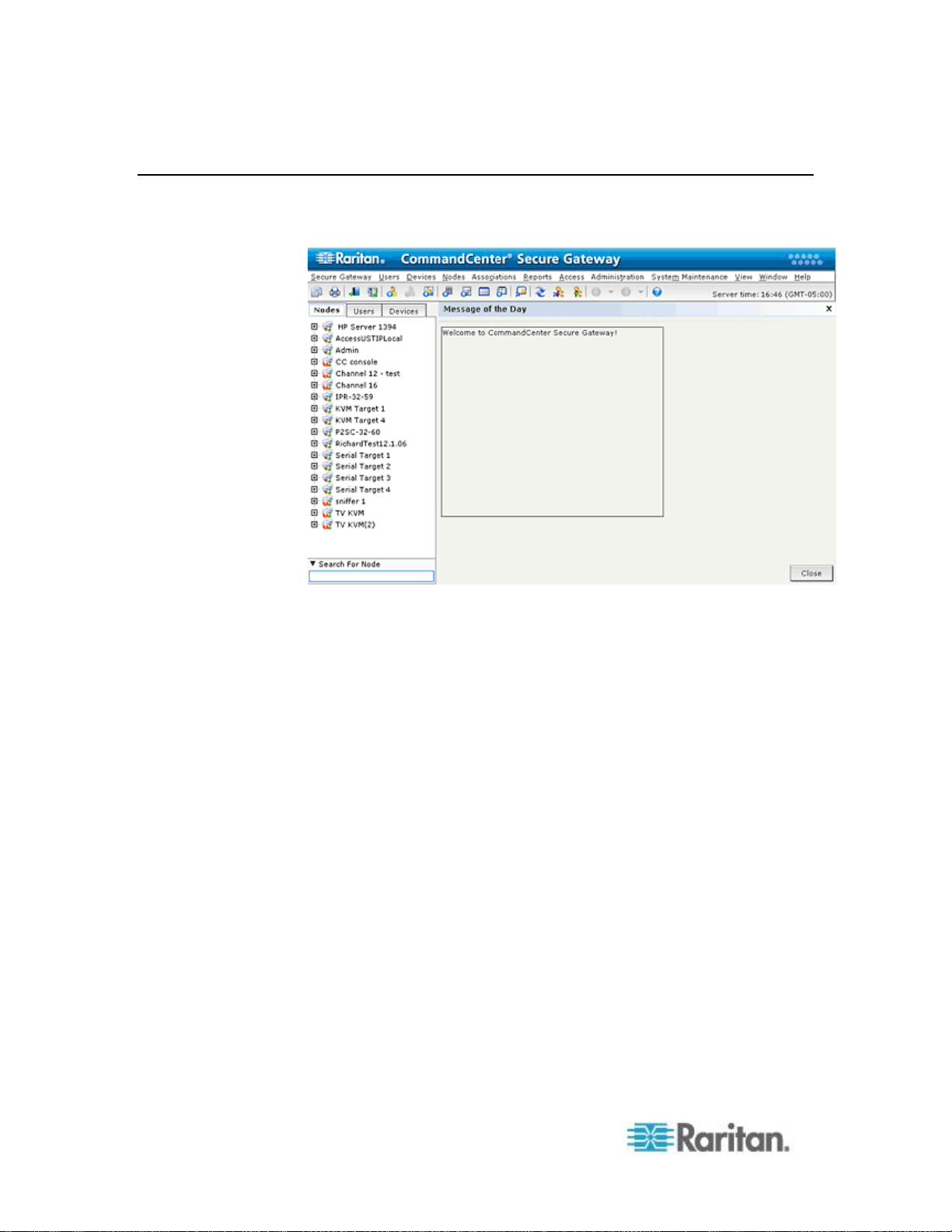
Chapter 2: Accessing CC-SG
8
CC-SG Admin Client
Upon valid login, the CC-SG Admin Client appears.
Page 27

Chapter 2: Accessing CC-SG
9
Nodes tab: Click the Nodes tab to display all known target nodes in a
tree view. Click a node to view the Node Profile. Interfaces are
grouped under their parent nodes. Click the + and - signs to expand
or collapse the tree. Right-click an interface and select Connect to
connect to that interface. You can sort the nodes by Node Name
(alphabetically) or Node Status (Available, Busy, Unavailable).
Right-click the tree view, select Node Sorting Options, and then
select By Node Name or By Node Status.
Users tab: Click the Users tab to display all registered Users and
Groups in a tree view. Click the + and - signs to expand or collapse
the tree.
Devices tab: Click the Devices tab to display all known Raritan
devices in a tree view. Different device types have different icons.
Ports are grouped under their parent devices. Click the + and - signs
to expand or collapse the tree. Click a port to view the Port Profile.
Right-click a port and select Connect to connect to that port. You can
sort the ports by Port Name (alphabetical), Port Status (Available,
Busy, Unavailable) or Port Number (numerical). Right-click the tree
view, select Port Sorting Options, and then select By Node Name or
By Node Status.
Quick Commands toolbar: This toolbar offers shortcut buttons for
executing common commands.
Operation and Configuration menu bar: These menus contain
commands to operate and configure CC-SG. You can access some
of these commands by right-clicking on the icons in the Nodes,
Users, and Devices Selection tabs. The menus and menu items you
see are based on your user access privileges.
Server time: The current time and time zone as configured on
CC-SG in Configuration Manager. This time is used when scheduling
tasks in Task Manager. See Task Manager (on page 278). This time
may be different than the time your client PC uses.
Page 28

10
Before you can begin configuring and working in CC-SG, you must have
In This Chapter
Licensing - Getting Started - New and Existing Customers .................... 10
Licensing - Basic License Information ..................................................... 11
Licensing - New Customers - Physical Appliance ................................... 14
Licensing - Virtual Appliance with License Server .................................. 17
Licensing - Limited Operation Before License Install .............................. 28
Licensing - Existing Customers ............................................................... 29
Licensing - Rehosting .............................................................................. 29
Add a License .......................................................................................... 30
Confirming IP Address ............................................................................. 30
Setting CC-SG Server Time .................................................................... 30
Checking the Compatibility Matrix ........................................................... 31
Checking and Upgrading Application Versions ....................................... 32
Chapter 3
Getting Started
valid licenses installed. Then, upon first login, you should confirm the IP
address, set the CC-SG server time, and check the firmware and
application versions installed. You may need to upgrade the firmware
and applications.
Once you have completed your initial configurations, proceed to Guided
Setup. See Configuring CC-SG with Guided Setup (on page 33).
Licensing - Getting Started - New and Existing Customers
In CC-SG 5.0, Raritan introduces a new licensing technology.
You must have valid licenses installed before you can begin using
CC-SG 5.0. Until the licenses are installed, your CC-SG only allows
access to limited functions. See Licensing - Limited Operation Before
License Install (on page 28).
To get started with licensing:
If you're a new customer to CC-SG with a physical appliance, see
Licensing - New Customers - Physical Appliance (on page 14).
If you're a new customer to CC-SG with a virtual appliance, see
Licensing - Virtual Appliance with License Server (on page 17).
If you're an existing customer who is upgrading to CC-SG 5.0, see
Licensing - Existing Customers (on page 29).
Page 29
Chapter 3: Getting Started
11
Licensing - Basic License Information
CC-SG product
Description
Information needed to create license for
first time
CC-E1-128
CC-SG E1 Appliance,
includes 128 Node License
Host ID of the CC-SG unit
CC-E1-256
CC-SG E1 Appliance,
includes 256 Node License
Host ID of the CC-SG unit
CC-E1-512
CC-SG E1 Appliance,
includes 512 Node License
Host ID of the CC-SG unit
CC-V1-128
CC-SG V1 Appliance,
includes 128 Node License
Host ID of the CC-SG unit
Licenses are based on the number of nodes configured in CC-SG.
Your purchase of a physical or virtual appliance includes a license to use
a specific number of nodes. This "base license" enables CC-SG
functionality and includes licensing for up to the set number of nodes. If
you need more nodes, you will also purchase an Add-On license for
additional nodes. If you want to use the WS-API feature, you must also
purchase an Add-On license for WS-API access.
License files for physical appliances are associated with a specific
CC-SG unit's Host ID.
License files for virtual appliances are associated with a specific license
server's Host ID.
This means that license files are not transferable.
If you are a new customer with a physical appliance, you will
download your license files from the Raritan Licensing Page website.
See Licensing - New Customers - Physical Appliance (on page
14).
If you are an existing pre-5.0 customer, you do not need to download
license files. When a pre-5.0 CC-SG unit is upgraded to 5.0 or
higher, the licenses are converted to the new format. A new base
license and any applicable Add-On licenses are created and
automatically installed and checked out as needed to accommodate
your current configuration. See Licensing - Existing Customers
(on page 29)
If you are a virtual appliance customer, you must deploy a license
server. See Licensing - Virtual Appliance with License Server (on
page 17).
Available Licenses
Page 30

Chapter 3: Getting Started
12
CC-SG product
Description
Information needed to create license for
first time
CC-V1-256
CC-SG V1 Appliance,
includes 256 Node License
Host ID of the CC-SG unit
CCSG128-VA
CC-SG Virtual Appliance,
includes 128 Node License
Host ID of the Windows or Linux license
server
Hostname or IP address of the Windows or
Linux license server
CC-2XE1-512
Cluster Kit: 2 CC-SG E1
Appliances, includes 512 Node
License
Host IDs of each CC-SG unit in the cluster
CC-2XE1-1024
Cluster Kit: 2 CC-SG E1
Appliances, includes 1024 Node
License
Host IDs of each CC-SG unit in the cluster
CC-2XV1-256
Cluster Kit: 2 CC-SG V1
Appliances, includes 256 Node
License
Host IDs of each CC-SG unit in the cluster
Add-on Licenses
Licenses for additional nodes and
value added services, such as
WS-API.
Host ID of the CC-SG unit
Find Your Physical Appliance Host ID and Check Number of Nodes In Database
The License Manager page contains information about your licenses,
including the number of licensed nodes currently in your database. You
can retrieve the physical appliance Host ID from the License
Management page. You will need to enter your CommandCenter Secure
Gateway's Host ID when creating a license file on the Raritan Licensing
portal. See Licensing - New Customers - Physical Appliance (on
page 14) for details on getting your new license files.
If you have a virtual appliance, see Get Your License (on page 19) for
details on retrieving your license server Host ID.
To view your Host ID and check number of nodes in database:
1. Choose Administration > License Management.
2. The Host ID of the CommandCenter Secure Gateway unit you are
logged into displays in the License Management page. You can copy
and paste the Host ID. For virtual CC-SG, the Host ID displays in the
License Summary section after you have installed the license server.
The License Manager page is slightly different for physical and
virtual appliances.
Page 31

Chapter 3: Getting Started
13
3. Check the number of nodes in your database on this page. You can
determine how many more nodes you can add up to your licensed
limit.
Page 32

Chapter 3: Getting Started
14
Licensing - New Customers - Physical Appliance
If you are a new customer who has just purchased a physical CC-SG 5.0
appliance, follow these instructions to ensure that you have valid
licenses installed and activated.
Step 1 - Get your license:
1. The license administrator designated at time of purchase will receive
an email from Raritan Licensing Portal from the email address
licensing@raritan.com, with the subject line Thank You for
Registering.
2. Click the link in the email to go to the Software License Key Login
page on Raritan's website. Create a user account and login. The
username is your email address. The licensing account information
page opens. Your license files will be available shortly.
3. Check your email for another message from Raritan Licensing Portal
from the email address licensing@raritan.com, with the subject line
Your Raritan Commandcenter SG Software License Key is Available.
Page 33

Chapter 3: Getting Started
15
4. Click the link in the email to go to the Software License Key Login
page on Raritan's website and login with the user account just
created.
5. Click the Product License tab. The licenses you purchased display in
a list. You may have only 1 license, or multiple licenses. See
Available Licenses (on page 11).
6. To get each license, click Create next to the item in the list, then
enter the CommandCenter Secure Gateway Host ID. You can copy
and paste the Host ID from the License Management page. See
Find Your Host ID and Check Number of Nodes In Database (see
"Find Your Physical Appliance Host ID and Check Number of
Nodes In Database" on page 12).
7. Click Create License. The details you entered display in a pop-up.
Verify that your Host ID is correct.
Warning: Make sure the Host ID is correct! A license created with an
incorrect Host ID is not valid and requires Raritan Technical
Support's help to fix.
8. Click OK. The license file is created.
9. Click Download Now and save the license file.
Step 2: Install your license
1. Choose Administration > License Management.
2. Click Add License.
3. Read the license agreement and scroll down the whole text area,
then select the I Agree checkbox.
Page 34

Chapter 3: Getting Started
16
Step 3: Check out the licenses you want to activate:
You must check out licenses to activate the features.
Select a license from the list then click Check Out. Check out all the
licenses you want to activate.
Licensing - Clusters - New Customers
A Cluster Kit license enables 2 CC-SG physical units operating as a
cluster to share licenses. The system will allow limited operations until
the cluster is created and actively operating, and the license is installed
and checked out on the primary cluster node. The CC-SG units in the
cluster can temporarily operate as standalone units to allow for
independent maintenance of each unit. The 2 CC-SG units must be
re-joined for continuous full functionality. Clustering is not supported for
virtual appliances.
Note: If the standalone grace period expires, CC-SG operations are
limited until the cluster is joined. See Licensing - Limited Operation
Before License Install (on page 28).
When creating your cluster license file on the Raritan Licensing Portal,
you must enter the Host IDs for each CC-SG unit. Find these numbers
on the Administration > License Management page of each CC-SG unit.
To deploy a CC-SG cluster with a Cluster Kit license:
See Configuring CC-SG Clusters (on page 256) for full details on
CC-SG clusters.
1. Deploy both CC-SG units to be clustered. See the CC-SG Quick
Setup Guide for deployment details.
2. Find the Host IDs for each CC-SG unit. See Find Your Host ID and
Check Number of Nodes In Database (see "Find Your Physical
Appliance Host ID and Check Number of Nodes In Database" on
page 12).
3. Get the Cluster Kit license file. See Licensing - New Customers -
Physical Appliance (on page 14).
4. Create the cluster. See Create a Cluster (on page 257).
5. Install the license file on the primary node in the cluster.The file will
be copied to the secondary node when the cluster is created. See
Licensing - New Customers - Physical Appliance (on page 14) for
details on installing a license file.
6. Check out the licenses you want to activate. Make sure to check out
the Cluster Kit license. See Licensing - New Customers - Physical
Appliance (on page 14).
Page 35

Chapter 3: Getting Started
17
Licensing - Virtual Appliance with License Server
The CC-SG virtual appliance requires you to install a license server to
host your license. Raritan provides the license server software and tools
and a vendor daemon, which you install on a physical server. See
Virtual Appliance Installation Requirements (on page 17).
If you are a new customer who has just purchased a virtual CC-SG
appliance, follow these instructions to ensure that you have your license
server installed and valid licenses activated.
Virtual Appliance Installation Requirements
ESX 4.0 to deploy the CommandCenter Secure Gateway virtual
appliance
Must have a datastore with 40GB minimum available
Must have 2GB memory available
2 virtual NICs
A high availability cluster with shared storage is recommended
Client computer running vSphere Client 4.0
A physical Windows or Linux server, to host the Flexera™ FlexNet
Publisher® license server, and a supported OS
Flexera's lmgrd utility is supported on:
Windows 32-bit, x86 on Windows Server 2008, Windows Server
2003, Windows XP Professional with SP3, Windows Vista
(Ultimate), Windows 7 (Ultimate)
Linux 32-bit Linux Standard Base (LSB) 3.0 Certified, x86 on Red
Hat Enterprise Linux 4.0 and 5.0
The following files, which are available at
http://www.raritan.com/support/commandcenter-secure-gateway.
See Download Installation Files (on page 18) for details.
CommandCenter Secure Gateway Virtual Appliance .OVF file
Raritan vendor daemon file
Flexera FlexNet Publisher license server
Page 36

Chapter 3: Getting Started
18
Download Installation Files
The complete set of installation files is available at
http://www.raritan.com/support/CommandCenter-Secure-Gateway/.
You must log in to the Raritan Licensing Portal to access these files at
this link. See Get Your License (on page 19).
If you prefer not to download the .OVF file due to its size, the .OVF file is
also shipped to customers on the product DVD. The DVD does not
include the Flexera or vendor daemon files, so you must download them
from the website.
The installation files are packaged in two .ZIP files. The <release
number> part of the filename will contain the actual CC-SG release
number.
The vccsg_rel_<release number>_ovf.ZIP file contains:
.OVF file used to deploy the virtual appliance
The flexserver-11.8-raritan.ZIP file contains:
Raritan vendor daemons for Linux and Windows
Flexera™ FlexNet Publisher® license server tool kit for Linux and
Windows
Install License Server Software on a Linux or Windows Server
CommandCenter Secure Gateway virtual appliance requires the
Flexera™ FlexNet Publisher® license server software to be installed on a
physical server. See Requirements for supported servers.
Linux Server
1. Log in to the Linux server.
2. Add a user called flex to the system.
3. Log in as flex and open the terminal.
4. Copy the flexserverv11.8-linux.tar.gz file you downloaded to
home/flex. Unzip the contents to the same location.
5. Type the command:
tar -xvzf flexserverv11.8.tar.gz
The files are unpacked. The following directories are created:
flexserverv11.8
i86_lsb is created under flexserverv11.8
6. Unzip the 5-1-0-raritan-daemon/raritan-linux32-1.1.zip file to
home/flex.
Page 37

Chapter 3: Getting Started
19
7. Move the Raritan vendor daemon file using this command:
cp raritan /home/flex/flexserverv11.8/i86_lsb/
8. Enter this command:
chmod +x raritan
9. Make sure you have the redhat-lsb package installed. To install it,
run yum install redhat-lsb as root.
Windows Server
1. Unpack the flexserverv11.8-win.zip file to C:\ on the Windows server.
This will create a folder called flexnet-win.
2. Unpack the raritan-win32-1.0.zip to C:\flexnet-win\i86_n3\.
Get Your License
1. The license administrator designated at time of purchase will receive
an email from Raritan Licensing Portal from the email address
licensing@raritan.com, with the subject line Thank You for
Registering.
2. Click the link in the email to go to the Software License Key Login
page on Raritan's website. Create a user account and login. The
username is your email address. The licensing account information
page opens. Your license files will be available shortly.
Page 38

Chapter 3: Getting Started
20
3. Check your email for another message from Raritan Licensing Portal
from the email address licensing@raritan.com, with the subject line
Your Raritan Commandcenter SG Software License Key is Available.
4. Click the link in the email to go to the Software License Key Login
page on Raritan's website and login with the user account just
created.
5. Click the Product License tab. The licenses you purchased display in
a list. You may have only 1 license, or multiple licenses.
6. To get each license, click Create next to the item in the list. If you
have more than 1 license, create the base license first.
7. Select New License Server Deployment if this is the first time you are
creating a license. If you have multiple CC-SG deployments with
more than 1 license server, select Add to an Existing License Server
Deployment, then select the license server you want to add this
license to.
8. Select Single as the Deployment Mode and Path. Leave Vendor
Daemon Path blank then click Next.
9. Select Hostname or Host IP, then enter either the hostname or IP
address of the license server.
10. Enter the Host ID of the license server, using these instructions to
retrieve it. The Host ID is a long string of letters and numbers, such
as: A005B983-8DFE-D511-A510-00112FCB87F6.
To retrieve the Host ID of your license server, run the
dmidecode program on the license server from the directory.
Page 39

Chapter 3: Getting Started
21
Linux: su - root; dmidecode -s system-uuid
Windows: Use cd to change to the /flexnet-win/i86_n3
directory, then run dmidecode -s system-uuid
Enter the TCP port number that CC-SG will use to
communicate with the license server. The default port is
27000. If the license server is behind a firewall, make sure
the port number you enter is open
11. Click Create License. The details you entered display in a pop-up.
Verify that your Host ID is correct.
Warning: Make sure the Host ID is correct! A license created with an
incorrect Host ID is not valid and requires Raritan Technical
Support's help to fix.
12. Click OK. The license file is created.
13. Click Download Now and save the license file.
Copy the License File to the License Server
License files must be added to the license server. If you have more than
1 license file, you can copy and paste the full contents of each file into
one file and save it using a text editor on your license server. Make sure
that you save the file with the .LIC extension.
Linux Server
Copy the license file to /home/flex/flexserverv11.8/i86_lsb/
Windows Server
Copy the license file to c:\flexnet-win\i86_n3\
Start the License Server
Linux Server
1. cd /home/flex/flexserverv11.8/i86_lsb/
2. Run lmgrd to start the server. In the sample commands,
"license-file.lic" is the file name of the .LIC file. If you have more than
1 license file, you must specify each file name in the command,
separating the file names by a colon. See examples.
/lmgrd -c ./license-file.lic
/lmgrd -c ./license-file1.lic:license-file2.lic
Windows Server
1. Launch the Windows cmd.exe shell.
Page 40

Chapter 3: Getting Started
22
2. Enter this command to change to the directory.
cd c:\flexnet-win\i86_n3\
3. Run lmgrd to start the server. In the sample commands,
"license-file.lic" is the file name of the .LIC file. If you have more than
1 license file, you must specify each file name in the command,
separating the file names by a semicolon. See examples.
lmgrd -z -c license-file.lic
lmgrd -z -c license-file1.lic;license-file2.lic
Install CommandCenter Secure Gateway on VMware ESX Server 4.0
1. Connect to the ESX 4.0 from your client computer using vSphere
4.0.
2. Log in as a user that has permission to create, start, and stop virtual
machines.
3. Choose File > Deploy OVF Template.
4. Select Deploy From File then click Browse to go to the directory
where you unzipped the files. Select the .OVF file. Click Next.
5. Details about the virtual machine that will be created display. You
can change the default name of the virtual machine. Click Next.
6. Select the inventory location. Click Next.
7. Select the Host where you want to deploy the CommandCenter
Secure Gateway. A host that is part of a high availability cluster
is recommended for failover protection. Click Next.
8. If you selected a cluster, select the specific host. Click Next.
9. Choose the datastore where all files will be stored. Make sure the
datastore has 40GB free. Click Next.
10. Choose the network your CC-SG is being deployed on. Click Next.
11. View the summary then click Finish. Wait several minutes while the
virtual machine is created.
12. Power on the virtual machine.
13. Open the Console tab to access the Diagnostic Console of CC-SG.
Log in to Diagnostic Console to Set CC-SG IP Address
1. Log in as admin/raritan. Usernames and passwords are
case-sensitive.
2. You will be prompted to change the local console password.
a. Type the default password (raritan) again.
Page 41

Chapter 3: Getting Started
23
b. Type and then confirm the new password. The new password
must be a strong password consisting of at least eight characters
that are a combination of letters and numbers.
3. Press CTRL+X when you see the Welcome screen.
4. Choose Operation > Network Interfaces > Network Interface Config.
The Administrator Console appears.
5. In the Configuration field, select DHCP or Static. If you select Static,
type a static IP address. If needed, specify DNS servers, netmask,
and gateway address.
6. Select Save. Wait a few minutes as CC-SG restarts.
Default CC-SG Settings
IP Address: 192.168.0.192
Subnet Mask: 255.255.255.0
Username/Password: admin/raritan
Log in to CC-SG
1. Launch a supported browser and type the URL of the CC-SG:
https://<IP address>/admin.
For example, https://192.168.0.192/admin.
Note: The default setting for browser connections is HTTPS/SSL
encrypted.
2. When the security alert window appears, accept the connection.
3. You will be warned if you are using an unsupported Java Runtime
Environment version. Follow the prompts to either download the
correct version, or continue. The Login window appears.
4. Type the default username (admin) and password (raritan) and click
Login.
The CC-SG Admin Client opens.
Install and Check Out Your License
1. Choose Administration > License Management.
2. Click Add License.
3. Read the license agreement and scroll down the whole text area,
then select the I Agree checkbox.
4. Click Browse, then select the base virtual appliance license file.
5. Click Open. CC-SG connects with the license server and retrieves a
list of licensed features. The features display in a list.
Page 42

Chapter 3: Getting Started
24
6. Select the CCSG128-VA base license then click Check-Out to
activate it.
7. To activate Add-On licenses, select each license then click
Check-Out.
See the CC-SG Administrators Guide for more details about licenses.
See the Flexera™ FlexNet Publisher® documentation for more details
about managing your license server. You can download the FlexNet
Publisher License Administration Guide for FlexNet Publisher Licensing
Toolkit 11.8 from www.flexera.com, under Support > Documentation
Center.
License Server Communication
The connection between the CC-SG virtual appliance and the license
server must be maintained. CC-SG uses this connection to make sure
the license server is up, to determine which license files are available,
and when checking in and checking out licenses.
Access to Licenses
All licenses that are checked out must be available on the license server
at all times. If a license file is moved or deleted from the license server,
CC-SG will not be able to verify the license when it polls the license
server. If a license that is checked out cannot be found on the license
server, CC-SG terminates access.
To prevent loss of access, always check in a license before moving or
deleting it from the license server.
License Server Outages
If CC-SG cannot connect with the license server, your licenses will
remain valid for a grace period of 7 days. Each time you login to CC-SG,
a message displays to remind you of the last day that access will be
allowed unless the connection with the license server resumes.
If the 7-day grace period ends without restoring the connection to the
license server, your checked-out licenses will be checked in. CC-SG
terminates access. You will be able to access limited options in CC-SG.
See Licensing - Limited Operation Before License Install (on page
28).
When the license server is up again, you must check out each license
again to resume normal operation. See Install and Check Out Your
License (on page 23).
Page 43

Chapter 3: Getting Started
25
Restart License Servers After an Outage
Command
Description
lmborrow
Allows a user to check out a feature and
borrow it for a specified period although
disconnected from the network.
lmdiag
Allows user to diagnose problems when
they cannot checkout a feature. Will
attempt feature check out and indicates
success/failure of the attempt.
lmdiag -c <license file name>
<feature name> -n
If the license server goes down, and then resumes operation, or if you
move, add or delete license files, you should restart the license server.
Restarting the license server ensures that CC-SG is synchronized with
the most current information.
Note: A Windows license server will synchronize automatically after an
outage. A Linux license server will synchronize after a 2-hour timeout,
but restarting it will synchronize it immediately after an outage.
To restart a license server:
Run the command lmdown for graceful shutdown of the license server.
Command Line Utilities for Managing License Server
The following utilities are installed when you install your license server
software. You can execute each from the command line to manage the
license server.
For the examples, use these values for the items in brackets.
<feature name> is the value in the Feature column on the Administration
> License Manager page in the Admin Client. For example,
"CCSG128-VA" is the feature name of the virtual appliance base license.
<license file name> is the file name of the license file installed, as saved
on your license server.
See the Flexera™ FlexNet Publisher® documentation for more details
about managing your license server. You can download the FlexNet
Publisher License Administration Guide for FlexNet Publisher Licensing
Toolkit 11.8 from www.flexera.com, under Support > Documentation
Center.
Page 44

Chapter 3: Getting Started
26
lmdown
Allows for the graceful shutdown of
selected license daemons.
lmdown -vendor raritan is used to
shut down the Raritan vendor daemon
lmhostid
Allows the user to retrieve the host ID of
the current platform.
Includes the –uuid, and, –hostdomain or
–internet arguments
lminstall
Allows conversion of licenses between
readable text format and decimal format.
lmnewlog
Move the existing Report log information
to a new file and start a new report with
original report log file name.
lmpath
Add to, override, or get the current license
path settings.
lmremove
Remove a single user’s license for a
specified feature.
The license server manager can be
configured to prevent unauthorized
execution of lmremove.
lmreread
lmreread – vendor raritan is used to
cause the Raritan vendor daemon to
re-read the license and options files
lmswitchr
Closes the existing report log and starting
a new report log with a new file name.
It can also be used to start a new report
log file if one does not already exist.
lmswitch
Closes the existing debug log for a
vendor daemon and starts a new debug
log for that vendor daemon with a new file
name.
It can also be used to start a new debug
log file written by the vendor daemon if
one does not already exist.
lmstat
Retrieves and displays license file status,
feature availability and usage information
that it receives from the license server.
lmstat -c <license file name> -f
<feature name>
Page 45

Chapter 3: Getting Started
27
lmver
Reports the version of a FLEXnet
Publisher library or binary file, such as
lmgrd, lmadmin, lmdown, vendor daemon.
Install or Upgrade VMware Tools
VMware Tools is recommended by VMware for all virtual machine
deployments. Once you install VMware Tools on your CommandCenter
Secure Gateway virtual appliance, you can follow this process to
upgrade it when VMware makes a new release.
The virtual CC-SG OVF package has a version of VMware Tools
installed by default.
To install or upgrade VMware Tools:
1. Login to the vSphere client and connect to the ESX host that is
hosting the CC-SG virtual appliance.
2. Select the virtual machine then click the Console tab. The Diagnostic
Console displays.
3. Right-click the virtual machine, then choose Guest > Install/Upgrade
VMware Tools. This mounts the files onto the virtual machine so that
CC-SG can do the installation.
4. Open a browser and login to the Admin Client.
5. Choose System Maintenance > Install / Upgrade VMware Tools.
When the installation is complete, a success message displays.
Configure Backups and Snapshots of Virtual Appliance and Storage Servers
Once the CC-SG virtual appliance is deployed, make sure to configure
backups of the virtual appliance through VMware®, and of the storage
servers used by the virtual appliance.
You should also enable snapshots through VMware.
See the VMware documentation at
http://www.vmware.com/support/pubs/vs_pubs.html for details on
configuring these features.
Virtual Appliances with Remote Storage Servers
If your CC-SG virtual appliance uses a remote server for file storage, and
access to that storage is lost, you may experience an interruption in
accessing CC-SG until the storage server has completely booted up.
You may see a Problems Retrieving Configuration Data message.
Page 46

Chapter 3: Getting Started
28
Licensing - Limited Operation Before License Install
Until you have installed and checked out the proper licenses, CC-SG
operations are limited. Only the following menu choices are enabled.
Diagnostic Console: To retrieve necessary information and logs,
configure network interfaces.
Note: You can access both the Administrator Console and Status
Console interfaces via VGA/Keyboard/Mouse Port (if applicable),
serial port (if applicable) or SSH. Status Console interface is also
available from a Web interface when enabled.
Change Password
Secure Gateway: To view Message Of The Day, Print, Print Screen,
Logout, and Exit.
Administration > Cluster Configuration: To configure the cluster and
assign roles to the cluster nodes. Building the cluster is a
pre-requisite for operating with a cluster-based license. Clusters are
available on physical appliances only.
Administration > License Manager: To allow uploading and removing
license files, and license check-out and check-in.
System Maintenance: The following menu choices are enabled.
Restore: To allow restore of licenses to CC-SG, in case you do a
full reset and remove the licenses by mistake.
Maintenance Mode: To enter and exit Maintenance Mode as
needed to create cluster or perform upgrades.
Restart
Upgrade
Shutdown
View
Help: To view online help documentation.
Page 47

Chapter 3: Getting Started
29
Licensing - Existing Customers
If you are an existing CC-SG customer, with a physical CC-SG
appliance, when you upgrade your CC-SG unit to 5.0 or higher, a license
file is created and installed that allows you to continue using CC-SG with
the number of nodes configured at the time of upgrade.
All existing customers must upgrade to 5.0 before upgrading to any
release higher than 5.0.
Follow the steps in this topic to confirm your license files are in place
after upgrade to 5.0.
Step 1: Upgrade to 5.0:
See Upgrading CC-SG (on page 229).
Step 2: View your license files:
1. In the Admin Client, choose Administration > License Management.
The License Manager page opens.
The License Summary section shows high-level information
about your license or licenses. You can view the CC-SG Host ID
associated with the license file.
The number of nodes in use and number of nodes allowed is
listed in the center of the page.
Licensing - Rehosting
Physical appliance licenses are associated with one specific CC-SG unit.
Virtual appliance licenses are associated with one specific license
server.
If these items change, your license file is assigned the wrong Host ID, or
anything happens that would result in a mismatch between the license
file and your CC-SG system, you must obtain a new license file with the
correct Host ID.
To get a new license file with a different Host ID:
Contact Raritan Technical Support. See Technical Support Contacts
(on page 2).
Note: If you discover that the number of nodes allowed is fewer than
the number you originally purchased a license for, contact your
Raritan Sales person.
Page 48

Chapter 3: Getting Started
30
Add a License
You can add a license to CC-SG if you purchase a new add-on license,
or need to replace your licenses.
When replacing licenses, add the base license first. Add-on licenses
associated with the previous base license will be deleted automatically if
they are not valid with the new base license, either because they are of a
different type, such as standalone or cluster, or if the host IDs are
different.
See Licensing FAQs (on page 387) for complete rules for license
replacement.
To add a license:
1. Choose Administration > License Management.
2. Click Add License.
3. Read the license agreement and scroll down the whole text area,
then select the I Agree checkbox.
4. Click Browse, then select the license file.
5. Click Open.
Note: If you are using a license server, CC-SG will contact the
license server and display the full list of features found on the server.
6. Select the features you want to activate, then click Check Out.
Confirming IP Address
1. Choose Administration > Configuration.
2. Click the Network Setup tab.
3. Check that the network settings are correct, and make changes if
needed. See About Network Setup (on page 242). Optional.
4. Click Update Configuration to submit your changes.
5. Click Restart Now to confirm your settings and restart CC-SG.
Setting CC-SG Server Time
CC-SG's time and date must be accurately maintained to provide
credibility for its device-management capabilities.
Important: The Time/Date configuration is used when scheduling
tasks in Task Manager. See
set on your client PC may be different than the time set on CC-SG.
Task Manager
(on page 278). The time
Page 49

Chapter 3: Getting Started
31
Only the CC Super-User and users with similar privileges can configure
Time and Date.
Changing the time zone is disabled in a cluster configuration.
To configure the CC-SG server time and date:
1. Choose Administration > Configuration.
2. Click the Time/Date tab.
a. To set the date and time manually:
Date - click the drop-down arrow to select the Month, use the up
and down arrows to select the Year, and then click the Day in
the calendar area.
Time - use the up and down arrows to set the Hour, Minutes, and
Seconds, and then click the Time zone drop-down arrow to
select the time zone in which you are operating CC-SG.
a. To set the date and time via NTP: Select the Enable Network
Time Protocol checkbox at the bottom of the window, and then
type the IP addresses for the Primary NTP server and the
Secondary NTP server in the corresponding fields.
Note: Network Time Protocol (NTP) is the protocol used to
synchronize the attached computer's date and time data with a
referenced NTP server. When CC-SG is configured with NTP, it can
synchronize its clock time with the publicly available NTP reference
server to maintain correct and consistent time.
3. Click Update Configuration to apply the time and date changes to
CC-SG.
4. Click Refresh to reload the new server time in the Current Time field.
Choose System Maintenance > Restart to restart CC-SG.
Checking the Compatibility Matrix
The Compatibility Matrix lists the firmware versions of Raritan devices
and software versions of applications that are compatible with the current
version of CC-SG. CC-SG checks against this data when you add a
device, upgrade device firmware, or select an application for use. If the
firmware or software version is incompatible, CC-SG displays a message
to warn you before you continue. Each version of CC-SG will support
only the current and previous firmware versions for Raritan devices at
the time of release. You can view the compatibility matrix on the Raritan
Support web site.
To check the Compatibility Matrix:
Choose Administration > Compatibility Matrix.
Page 50

Chapter 3: Getting Started
32
Checking and Upgrading Application Versions
Check and upgrade the CC-SG applications, including Raritan Console
(RC) and Raritan Remote Client (RRC).
To check an application version:
1. Choose Administration > Applications.
2. Select an Application name from the list. Note the number in the
Version field. Some applications do not automatically show a version
number.
To upgrade an application:
If the application version is not current, you must upgrade the
application. You can download the application upgrade file from the
Raritan website. For a complete list of supported application versions,
see the Compatibility Matrix on the Raritan Support website.
The best practice is to enter Maintenance Mode before upgrading
applications. See Entering Maintenance Mode (on page 222).
1. Save the application file to your client PC.
2. Click the Application name drop-down arrow and select the
application that must be upgraded from the list. If you do not see the
application, you must add it first. See Add an Application (on page
239).
3. Click Browse, locate and select the application upgrade file from the
dialog that appears then click Open.
4. The application name appears in the New Application File field in the
Application Manager screen.
5. Click Upload. A progress window indicates that the new application
is being uploaded. When complete, a new window will indicate that
the application has been added to the CC-SG database and is
available to use.
6. If the Version field does not automatically update, type the new
version number in the Version field. The Version field will
automatically update for some applications.
7. Click Update.
Note: Users who were logged in during the upgrade must log out of
CC-SG then log in again to ensure that the new version of the application
is launched. Also, see Older Version of Application Opens After
Upgrading (on page 239).
Page 51

33
Guided Setup offers a simple way to complete initial CC-SG
In This Chapter
Before You Use Guided Setup ................................................................ 33
Associations in Guided Setup ................................................................. 34
Device Setup ........................................................................................... 34
Creating Groups ...................................................................................... 36
User Management ................................................................................... 38
Chapter 4
Configuring CC-SG with Guided Setup
configuration tasks once the network configuration is complete. The
Guided Setup interface leads you through the process of defining
Associations, discovering and adding devices to CC-SG, creating device
groups and node groups, creating user groups, assigning policies and
privileges to user groups, and adding users. Once you have completed
Guided Setup, you can always edit your configurations individually.
Guided Setup is divided into four tasks:
Associations - Define the categories and elements that you use to
organize your equipment. See Associations in Guided Setup (on
page 34).
Device Setup - Discover devices in your network and add them to
CC-SG. Configure device ports. See Device Setup (on page 34).
Create Groups - Categorize the devices and nodes that CC-SG
manages into groups and create full access policies for each group.
See Creating Groups (on page 36).
User Management - Add users and user groups to CC-SG, and
select the policies and privileges that govern user access within
CC-SG and to devices and nodes. See User Management (on page
38).
See Naming Conventions (on page 389) for details on CC-SG's rules
for name lengths.
Before You Use Guided Setup
Before proceeding with CC-SG configuration, you must complete system
configuration.
Configure and install Dominion series and IP-Reach appliances (both
serial and KVM devices), including assigning an IP address.
Page 52

Chapter 4: Configuring CC-SG with Guided Setup
34
Associations in Guided Setup
Create Categories and Elements
To create categories and elements in Guided Setup:
1. In the Guided Setup window, click Associations, and then click
Create Categories in the left panel to open the Create Categories
panel.
2. In the Category Name field, type the name of a category into which
you want to organize your equipment, such as “Location.”
3. In the Applicable for field, indicate whether you want the category to
be available for devices, nodes, or both. Click the Applicable for
drop-down menu and select a value from the list.
4. In the Elements table, type the name of an element within the
category, such as “Raritan US.”
Click the Add New Row icon to add more rows to the
Elements table.
To delete an element, select its row, and then click the Delete
Row icon .
5. Repeat these steps until you have added all the elements within the
category to the Elements table.
Device Setup
6. To create another category, click Apply to save this category, and
then repeat the steps in this section to add additional categories.
Optional
7. When you have finished creating categories and elements, click OK.
The Association Summary panel displays a list of the categories and
elements that you created.
8. Click Continue to start the next task, Device Setup. Follow the steps
in the next section.
The second task of Guided Setup is Device Setup. Device Setup allows
you to search for and discover devices in your network, and add those
devices to CC-SG. When adding devices, you may select one element
per category to be associated with the device.
Important: Ensure that no other users are logged on to the device
during CC-SG configuration.
Page 53

Chapter 4: Configuring CC-SG with Guided Setup
35
Discover and Add Devices
The Discover Devices panel opens when you click Continue at the end of
the Associations task. You can also click Device Setup, and then click
Discover Devices in the Guided Tasks tree view in the left panel to open
the Discover Devices panel.
To discover and add devices in Guided Setup:
1. Type the IP address range in which you want to search for devices in
the From address and To address fields.
2. Type the subnet mask in which you want to search for devices in the
Mask field.
3. In the Device types list, select the type of device you want to search
for in the range specified. Press and hold down the Ctrl key while
you click device types to select multiple device types.
4. Select the Broadcast discovery checkbox if searching for devices on
the same subnet on which CC-SG resides. Deselect the Broadcast
discovery checkbox to discover devices across all subnets.
5. Click Discover.
6. If CC-SG has discovered devices of the specified type and in the
specified address range, the devices appear in a table in the bottom
section of the Discover Devices panel. Click the black arrow at the
top of the panel to hide the top section, expanding your view of the
discovery results in the bottom section of the panel.
7. In the table of discovered devices, select the device you want to add
to CC-SG, and then click Add. The Add Device panel opens. The
Add Device panel is slightly different, depending on the type of
device you are adding.
8. You can change the Device name and Description by typing new
information in the corresponding fields.
9. Confirm that the IP address you assigned when you prepared the
device to be added to CC-SG displays in the Device IP or Hostname
field, or type the correct address in the field if necessary.
10. The TCP Port Number field will be populated automatically based on
the device type.
11. Type the Username and Password you created when you prepared
the device to be added to CC-SG in the corresponding fields.
12. In the Heartbeat timeout field, type the number of seconds that
should elapse before timeout between the device and CC-SG.
13. If you are adding a Dominion SX or Dominion KXII version 2.2 or
later device, select the Allow Direct Device Access checkbox if you
want to allow local access to the device. Deselect the Local access:
Allowed checkbox if you do not want to allow local access to the
device.
Page 54

Chapter 4: Configuring CC-SG with Guided Setup
36
14. If you are manually adding a PowerStrip device, click the Number of
ports drop-down arrow and select the number of outlets the
PowerStrip contains.
15. If you are adding an IPMI Server, type an Interval, used to check for
availability, and an Authentication Method, which needs to match
what has been configured on the IPMI Server, in the corresponding
fields.
16. If you want to configure all available ports on the device, select the
Configure all ports checkbox. CC-SG will add all ports on the device
to CC-SG and create a node for each port.
17. In the Device Associations section at the bottom of the panel, click
the drop-down arrow in the Element column that corresponds to
each Category you want to assign to the device, and then select the
element you want to associate with the device from the list.
Note: A node or device that has more than one element of the same
category assigned to it will appear more than once in a Custom View
based on categories and elements.
18. If you want the Element to apply to the device and to the nodes
connected to the device, select the Apply to Nodes checkbox.
19. If you want to add another device, click Apply to save this device,
and repeat these steps. Optional.
Creating Groups
20. When you have finished adding devices, click OK. The Device
Summary panel displays a list of the devices that you added.
21. Click Continue to start the next task, Create Groups. Follow the
steps in the next section.
The third task of Guided Setup is Create Groups. Create Groups allows
you to define groups of devices and groups of nodes and specify the set
of devices or nodes included in each group. Administrators can save
time by managing groups of similar devices and nodes, rather than
managing each device or node individually.
Add Device Groups and Node Groups
To add device groups and node groups in Guided Setup:
1. The Device Group: New panel opens when you click Continue at the
end of the Device Setup task. You can also click Create Groups, and
then click Add Device Groups in the Guided Tasks tree view in the
left panel to open the Device Group: New panel.
2. In the Group Name field, type a name for a device group you want to
create.
Page 55

Chapter 4: Configuring CC-SG with Guided Setup
37
3. There are two ways to add devices to a group, Select Devices and
Describe Devices. The Select Devices tab allows you to select which
devices you want to assign to the group by selecting them from the
list of available devices. The Describe Devices tab allows you to
specify rules that describe devices, and the devices whose
parameters follow those rules will be added to the group.
Select Devices
a. Click the Select Devices tab in the Device Group: New panel.
b. In the Available list, select the device you want to add to the
group, and then click Add to move the device into the Selected
list. Devices in the Selected list will be added to the group.
c. To remove a device from the group, select the device name in
the Selected list, and then click Remove.
d. You can search for a device in either the Available or Selected
list. Type the search terms in the field below the list, and then
click Go.
Describe Devices
a. Click the Describe Devices tab in the Device Group: New panel.
In the Describe Devices tab, you create a table of rules that
describe the devices you want to assign to the group.
b. Click the Add New Row icon to add a row to the table.
c. Double-click the cell created for each column to activate a
drop-down menu. Select the rule components you want to use
from each list.
4. Select the Create Full Access Policy for Group checkbox if you want
to create a policy for this device group that allows access to all
nodes and devices in the group at all times with control permission.
5. To add another device group, click Apply to save this group and
repeat these steps. Optional.
6. When you have finished adding device groups, click OK. The Node
Group: New panel opens. You can also click Create Groups, and
then click Add Node Groups in the Guided Tasks tree view in the left
panel to open the Node Group: New panel.
7. In the Group Name field, type a name for a node group you want to
create.
8. There are two ways to add nodes to a group, Select Nodes and
Describe Nodes. The Select Nodes section allows you to select
which nodes you want to assign to the group by selecting them from
the list of available nodes. The Describe Nodes section allows you to
specify rules that describe nodes, and the nodes whose parameters
follow those rules will be added to the group.
Page 56

Chapter 4: Configuring CC-SG with Guided Setup
38
Select Nodes
a. Click the Select Nodes tab in the Node Group: New panel.
b. In the Available list, select the node you want to add to the
group, and then click Add to move the node into the Selected
list. Nodes in the Selected list will be added to the group.
c. To remove a node from the group, select the node name in the
Selected list and click Remove.
d. You can search for a node in either the Available or Selected list.
Type the search terms in the field below the list, and then click
Go.
Describe Nodes
a. Click the Describe Nodes tab in the Node Group: New panel. In
the Describe Nodes tab, you create a table of rules that describe
the nodes you want to assign to the group.
b. Click the Add New Row icon to add a row to the table.
c. Double-click the cell created for each column to activate a
drop-down menu. Select the rule components you want to use
from each list. See Policies for Access Control (on page 175).
9. Select the Create Full Access Policy for Group checkbox if you want
to create a policy for this node group that allows access to all nodes
in the group at all times with control permission.
User Management
10. To add another node group, click Apply to save this group and
repeat these steps. Optional.
11. When you have finished adding node groups, click OK. The Groups
Summary panel displays a list of the groups that you added.
12. Click Continue to start the next task, User Management. Follow the
steps in the next section.
The fourth task of Guided Setup is User Management. User
Management allows you to select the Privileges and Policies that govern
the access and activities of groups of users. Privileges specify which
activities the members of the user group can perform in CC-SG. Policies
specify which devices and nodes the members of the user group can
view and modify. Policies are based on Categories and Elements. When
you have created the user groups, you can define individual users and
add them to the user groups.
Page 57

Chapter 4: Configuring CC-SG with Guided Setup
39
Add User Groups and Users
The Add User Group panel opens when you click Continue at the end of
the Create Groups task. You can also click User Management, and then
click Add User Group in the Guided Tasks tree view in the left panel to
open the Add User Group panel.
To add user groups and users in Guided Setup:
1. In the User Group Name field, type a name for the user group you
want to create. User group names can contain up to 64 characters.
2. In the Description field, type a description of the user group.
3. To set a maximum number of KVM sessions per user in this user
group when accessing devices that have this feature enabled, select
the Limit Number of KVM Sessions per Device checkbox, and select
the number of sessions allowed in the Max KVM Sessions (1-8) field.
Optional. See Limit the Number of KVM Sessions per User (on
page 162) for details.
4. Click the Privileges tab, and then select the checkboxes that
correspond to the Privileges, or types of CC-SG activities, that you
want to assign to the user group.
5. In the Node Access section, you can specify whether you want the
user group to have access to In band and Out of band nodes, and to
Power Management functions. Select the checkboxes that
correspond to the types of access you want to assign to the group.
6. Click the Policies tab.
7. In the All Policies list, select the Policy that you want to assign to the
user group and click Add to move the Policy to the Selected Policies
list. Policies in the Selected Policies list will be assigned to the user
group. Repeat this step to add additional policies to the user group.
8. To remove a policy from the user group, select the policy name in
the Selected Policies list, and then click Remove.
9. If you want to associate remotely authenticated users with Active
Directory modules, click the Active Directory Associations tab when
the AD-configured Active Directory Associations tab is not hidden.
Select the checkbox that corresponds with each Active Directory
module you want to associate with the user group.
10. To add another user group, click Apply to save this group and repeat
these steps. Optional.
11. When you have finished adding user groups, click OK. The Add User
panel opens. You can also click User Management, and then click
Add User in the Guided Tasks tree view in the left panel to open the
Add User panel.
12. In the Username field, type the name that the user you want to add
will use to log in to CC-SG.
Page 58

Chapter 4: Configuring CC-SG with Guided Setup
40
13. Select the Login Enabled checkbox if you want the user to be able to
log in to CC-SG.
14. Select the Remote Authentication checkbox only if you want the user
to be authenticated by an outside server, such as TACACS+,
RADIUS, LDAP, or AD. If you are using remote authentication, a
password is not required. The New Password and Retype New
Password fields will be disabled when Remote Authentication is
checked.
15. In the New Password and Retype New Password fields, type the
password that the user will use to log in to CC-SG.
16. Check the Force Password Change on Next Login if you want the
user to be forced to change the assigned password the next time the
user logs in.
17. Select the Force Password Change Periodically checkbox if you
want to specify how often the user will be forced to change the
password.
18. In the Expiration Period (Days) field, type the number of days that
the user will be able to use the same password before being forced
to change it.
19. In the Email address field, type the user's email address.
20. Click the User Group drop-down arrow and select the user group to
which you want to assign the user from the list.
21. If you want to add another user, click Apply to save this user, and
then repeat the steps in this section to add additional users.
22. When you have finished adding users, click OK. The User Summary
panel displays a list of the user groups and users that you added.
Optional.
Page 59

41
In This Chapter
About Associations .................................................................................. 41
Adding, Editing, and Deleting Categories and Elements ........................ 42
Adding Categories and Elements with CSV File Import .......................... 43
Category
Elements
OS Type
Unix, Windows, Linux
Department
Sales, IT, Engineering
Chapter 5
Associations, Categories, and Elements
About Associations
You can set up Associations to help organize the equipment that CC-SG
manages. Each Association includes a Category, which is the top-level
organizational group, and its related Elements, which are subsets of a
Category. For example, you may have Raritan devices that manage
target servers in data centers in America, Asia Pacific, and Europe. You
could set up an Association that organizes this equipment by location.
Then, you can customize the CC-SG to display your Raritan devices and
nodes according to your chosen Category-Location, and its associated
Elements - America, Asia Pacific, and Europe, in the CC-SG interface.
You can customize the CC-SG to organize and display your servers
however you like.
Association Terminology
Associations - the relationships between categories, elements of a
Category - a variable that contains a set of values called elements.
Elements - the values of a category. For example, the “America”
category, and nodes and devices.
An example of a category is Location, which may have elements
such as “America” and “Asia Pacific.” Another example of a category
is “OS Type,” which may have elements such as “Windows” or “Unix”
or “Linux.”
element belongs to the “Location” category.
Associations - Defining Categories and Elements
Raritan devices and nodes are organized by categories and elements.
Each category/element pair is assigned to a device, a node, or both.
A category is a group of similar elements.
Page 60

Chapter 5: Associations, Categories, and Elements
42
Policies also use categories and elements to control user access to
servers. For example, the category/element pair Location/America can
be used to create a Policy to control user access to servers in America.
See Policies for Access Control (on page 175).
You can assign more than one element of a category to a node or device
via CSV file import.
As you add devices and nodes to CC-SG, you will link them to your
predefined categories and elements. When you create node and device
groups and assign policies to them, you will use your categories and
elements to define which nodes and devices belong in each group.
How to Create Associations
There are two ways to create associations, Guided Setup and
Association Manager.
Guided Setup combines many configuration tasks into an automated
interface. Guided Setup is recommended for your initial CC-SG
configuration. Once you have completed Guided Setup, you can
always edit your configurations individually. See Configuring
CC-SG with Guided Setup (on page 33).
Association Manager allows you to work only with associations, and
does not automate any configuration tasks. You can use Association
Manager to edit your Associations after using Guided Setup, too.
See Adding, Editing, and Deleting Categories and Elements (on
page 42).
Adding, Editing, and Deleting Categories and Elements
Association Manager allows you to add, edit, or delete Categories and
Elements.
Note: By default, CC-SG keeps default category names "System Type"
and "US States and territories" in English.
Add a Category
To add a category:
1. Choose Associations > Association.
2. Click Add. The Add Category window opens.
3. Type a category name in the Category Name field. See Naming
Conventions (on page 389) for details on CC-SG's rules for name
lengths.
4. Select the Data Type for Elements.
Select String if the value is read as text.
Page 61

Chapter 5: Associations, Categories, and Elements
43
Select Integer if the value is a number.
5. In the Applicable For field, select whether this category applies to:
Devices, Nodes, or Device and Nodes.
6. Click OK to create the new category. The new category name
appears in the Category Name field.
Delete a Category
Deleting a category deletes all of the elements created within that
category. The deleted category will no longer appear in the Nodes or
Devices trees once the screen refreshes or the user logs out and then
logs back into CC-SG.
To delete a category:
1. Choose Associations > Association.
2. Click the Category Name drop-down arrow and select the category
you want to delete.
3. Click Delete in the Category panel of the screen to delete the
category. The Delete Category window opens.
4. Click Yes to delete the category.
Add an Element
To add an element:
1. Choose Associations > Association.
2. Click the Category Name drop-down arrow and select the category
to which you want to add a new element.
3. Click the Add a new row icon.
4. Type the new element name in the blank row. See Naming
Conventions (on page 389) for details on CC-SG's rules for name
lengths. Element names are case-sensitive.
5. Click OK to save your changes.
Adding Categories and Elements with CSV File Import
You can add categories and elements to CC-SG by importing a CSV file
that contains the values. You must have the User Security Management
and CC Setup and Control privileges to import and export categories and
elements.
Page 62

Chapter 5: Associations, Categories, and Elements
44
Categories and Elements CSV File Requirements
Column 1
Column 2
Column 3
Column 4
Column 5
ADD
CATEGORY
Category Name
Type
Apply
Values:
Integer
String
Default is
String.
Values:
Nodes
Devices
Both
Default is Both.
Column 1
Column 2
Column 3
Column 4
ADD
CATEGORYELEMENT
Category Name
Element Name
The categories and elements CSV file defines the categories, their
associated elements, their type, and whether they apply to devices,
nodes or both.
All CATEGORY and CATEGORYELEMENT records are related. A
CATEGORY record must have one or more CATEGORYELEMENT
records.
CATEGORYELEMENT records can be present without a
corresponding CATEGORY record if that CATEGORY already exists
in CC-SG. For example, if you are adding more elements to an
existing category, then you do not have to include a row to redefine
the category that the new elements belong to.
Export a file from CC-SG to view the Comments, which include all
tags and parameters needed to create a valid CSV file. See Export
Categories and Elements (on page 46).
Follow the additional requirements for all CSV files. See Common
CSV File Requirements (on page 369).
To add a category to the CSV file:
To add an element to the CSV file:
Page 63

Chapter 5: Associations, Categories, and Elements
45
Sample Categories and Elements CSV File
ADD, CATEGORY, OS, String, Node
ADD, CATEGORYELEMENT, OS, UNIX
ADD, CATEGORYELEMENT, OS, WINDOWS
ADD, CATEGORYELEMENT, OS, LINUX
ADD, CATEGORY, Location, String, Device
ADD, CATEGORYELEMENT, Location, Aisle 1
ADD, CATEGORYELEMENT, Location, Aisle 2
ADD, CATEGORYELEMENT, Location, Aisle 3
Import Categories and Elements
Once you've created the CSV file, validate it to check for errors then
import it.
Duplicate records are skipped and are not added.
To import the CSV file:
1. Choose Administration > Import >Import Categories.
2. Click Browse and select the CSV file to import. Click Open.
3. Click Validate. The Analysis Report area shows the file contents.
If the file is not valid, an error message appears. Click OK and
look at the Problems area of the page for a description of the
problems with the file. Click Save to File to save the problems
list. Correct your CSV file and then try to validate it again. See
Troubleshoot CSV File Problems (on page 371).
4. Click Import.
5. Check the Actions area to see the import results. Items that imported
successfully show in green text. Items that failed import show in red
text. Items that failed import because a duplicate item already exists
or was already imported also show in red text.
6. To view more import results details, check the Audit Trail report. See
Audit Trail Entries for Importing (on page 370).
Page 64

Chapter 5: Associations, Categories, and Elements
46
Export Categories and Elements
The export file contains comments at the top that describe each item in
the file. The comments can be used as instructions for creating a file for
importing.
To export categories and elements:
1. Choose Administration > Export > Export Categories.
2. Click Export to File.
3. Type a name for the file and choose the location where you want to
save it
4. Click Save.
The first time you save the file in Excel, you must choose Save As and
MAKE SURE to select CSV as the file type. After that, Excel will
continue to save the file as CSV.
If you don't set the file type correctly, the file will corrupt and cannot be
used to import.
Page 65

47
In This Chapter
Viewing Devices ...................................................................................... 48
Searching for Devices ............................................................................. 52
Discovering Devices ................................................................................ 53
Adding a Device ...................................................................................... 54
Editing a Device ....................................................................................... 57
Change the HTTP and HTTPS Ports for a KX2 Device .......................... 57
Editing a PowerStrip Device or a Dominion PX Device .......................... 57
Adding Notes to a Device Profile ............................................................. 58
Adding Location and Contacts to a Device Profile .................................. 59
Deleting a Device .................................................................................... 59
Configuring Ports ..................................................................................... 60
Editing a Port ........................................................................................... 61
Deleting a Port ......................................................................................... 62
Configuring a Blade Chassis Device Connected to KX2 ......................... 63
Restore Blade Servers Ports to Normal KX2 Ports ................................. 68
Bulk Copying for Device Associations, Location and Contacts ............... 69
Configuring Analog KVM Switches Connected to KX2 2.3 or Higher ..... 70
Device Group Manager ........................................................................... 71
Adding Devices with CSV File Import ...................................................... 77
Upgrading a Device ................................................................................. 82
Backing Up a Device Configuration ......................................................... 83
Restoring Device Configurations ............................................................. 84
Copying Device Configuration ................................................................. 87
Restarting a Device ................................................................................. 88
Pinging the Device ................................................................................... 88
Pausing CC-SG's Management of a Device ........................................... 88
Resuming Management of a Device ....................................................... 89
Pause and Resume Management of Devices Using a Scheduled Task . 89
Device Power Manager ........................................................................... 90
Launching a Device's Administrative Page ............................................. 90
Disconnecting Users ................................................................................ 91
Special Access to Paragon II System Devices........................................ 91
Chapter 6
Devices, Device Groups, and Ports
To add Raritan PowerStrip Devices that are connected to other Raritan
devices to CC-SG, see Managed PowerStrips (on page 93).
Note: To configure iLO/RILOE devices, IPMI devices, Dell DRAC
devices, IBM RSA devices, or other non-Raritan devices, use the Add
Node menu and add these items as an interface. See Nodes, Node
Groups, and Interfaces (on page 101).
Page 66

Chapter 6: Devices, Device Groups, and Ports
48
Viewing Devices
Icon
Meaning
Device available
KVM port available or connected
KVM port inactive
Serial port available
The Devices Tab
Click the Devices tab to display all devices under CC-SG management.
Each device's configured ports are nested under the devices they belong
to. Devices with configured ports appear in the list with a + symbol. Click
the + or - to expand or collapse the list of ports.
Device and Port Icons
For easier identification, KVM, Serial, and Power devices and ports have
different icons in the Devices tree. Hold the mouse pointer over an icon
in the Devices tree to view a tool tip containing information about the
device or port.
Page 67

Chapter 6: Devices, Device Groups, and Ports
49
Icon
Meaning
Serial port unavailable
Ghosted port (See Raritan's Paragon II
User Guide for details on Ghosting
Mode.)
Device paused
Device unavailable
Power strip
Outlet port
Blade chassis available
Blade chassis unavailable
Blade server available
Blade server unavailable
Port Sorting Options
Configured ports are nested under their parent devices in the Devices
tab. You can change the way ports are sorted. Ports arranged by status
are sorted alphabetically within their connection status grouping. Devices
will also be sorted accordingly.
To sort the ports in the Devices tab:
1. Choose Devices > Port Sorting Options.
2. Select By Port Name, By Port Status or By Port Number to arrange
the ports within their devices alphabetically by name or by availability
status or numerically by port number.
Page 68

Chapter 6: Devices, Device Groups, and Ports
50
Note: For blade servers without an integrated KVM switch, such as HP
BladeSystem servers, their parent device is the virtual blade chassis that
CC-SG creates, not the KX2 device. These servers will be sorted only
within the virtual blade chassis device so they will not appear in order
with the other KX2 ports unless you restore these blade servers ports to
normal KX2 ports. See Restore Blade Servers Ports to Normal KX2
Ports (on page 68).
Device Profile Screen
When you select a device in the Devices tab, the Device Profile screen
appears, displaying information about the selected device.
When a device is down, the information in the Device Profile screen is
read-only. You can delete a device that is down. See Deleting a Device
(on page 59).
Page 69

Chapter 6: Devices, Device Groups, and Ports
51
The Device Profile includes tabs that contain information about the
device.
Associations tab
The Associations tab contains all categories and elements assigned to
the node. You can change the associations by making different
selections. See Associations, Categories, and Elements (on page 41).
Location & Contacts tab
The Location & Contacts tab contains information about a device's
location and contact information, such as phone numbers, that you may
need when working on a device. You can change the information in the
fields by typing in new information. See Adding Location and Contacts
to a Device Profile (on page 59).
Notes tab
The Notes tab contains a tool that enables users to leave notes about a
device for other users to read. All notes display in the tab with the date,
username, and IP address of the user who added the note.
If you have the Device, Port, and Node Management privilege, you can
clear all notes from the node profile by clicking Clear.
See Adding Notes to a Device Profile (on page 58).
Blades tab
Blade chassis nodes, such as IBM BladeCenter, include the Blades tab.
The Blades tab contains information about the blade servers residing in
the blade chassis.
In addition to viewing the blade information, you can configure the
unconfigured blade servers by selecting the checkboxes that correspond
to them in this tab.
See Configuring Slots on a Blade Chassis Device (on page 65).
Topology View
Topology View displays the structural setup of all connected appliances
in your configuration.
Until you close the Topology View, this view replaces the Device Profile
screen that normally appears when a device is selected.
To open the topology view:
1. Click the Devices tab and select the device whose topological view
you want to see.
Page 70

Chapter 6: Devices, Device Groups, and Ports
52
2. Choose Devices > Device Manager > Topology View. The Topology
Wildcard
Description
?
Indicates any character.
[-]
Indicates a character in range.
*
Indicates zero or more characters.
Example
Description
KX?
Locates KX1, and KXZ, but not
KX1Z.
KX*
Locates KX1, KX, KX1, and
KX1Z.
KX[0-9][0-9]T
Locates KX95T, KX66T, but not
KXZ and KX5PT.
Right Click Options in the Devices Tab
You can right-click a device or port in the Devices tab to display a menu
of commands available for the selected device or port.
Searching for Devices
The Devices tab provides the ability to search for devices within the tree.
Searching will only return devices as results and will not include port
names. The method of searching can be configured in My Profile. See
Change your default search preference (on page 172).
To search for a device:
At the bottom of the Devices Tab, type a search string in Search For
Wildcards are supported in the search string. See Wildcards for
Wildcards for Search
View for the selected device appears.
Click + or - to expand or collapse the view.
Device field, then press the Enter key.
Search (on page 52).
Wildcard Examples
Page 71

Chapter 6: Devices, Device Groups, and Ports
53
Discovering Devices
Discover Devices initiates a search for all devices on your network. After
discovering the devices, you may add them to CC-SG if they are not
already managed.
1. Choose Devices > Discover Devices.
2. Type the range of IP addresses where you expect to find the devices
3. Check Broadcast discovery if searching for devices on the same
4. To search for a particular type of device, select it in the list of Device
5. Select the Include IPMI Agents checkbox to find targets that provide
To discover devices:
in the From Address and To Address fields. The To Address should
be larger than the From Address. Specify a mask to apply to the
range. If a mask is not specified, then a broadcast address of
255.255.255.255 is sent, which broadcasts to all local networks. To
discover devices across subnets, you must specify a mask.
subnet on which CC-SG resides. Clear Broadcast Discovery to
discover devices across different subnets.
types. By default, all device types are selected. Use CTRL+click to
select more than one device type.
IPMI power control.
6. Click Discover to start the search. At any time during the discovery,
you can click Stop to discontinue the discovery process. Discovered
devices appear in a list.
7. To add one or more discovered devices to CC-SG, select the
devices from the list and click Add. The Add Device screen appears
with some of the data already populated.
If you selected more than one device to add, you can click Previous
and Skip at the bottom of the screen to navigate through the Add
Device screens for the devices you want to add.
8. The Add Device page is different for different device types. See the
instructions on adding each device type CC-SG discovered.
For KVM or Serial devices, see Add a KVM or Serial Device (on
page 54).
For Powerstrips, see Add a PowerStrip Device (on page 56).
For Dominion PX powerstrips on the IP network, see Add a
Dominion PX Device (on page 56).
9. Click Apply to add a discovered device and continue to the next
discovered device. Click OK to add the current discovered device
and stop the process of adding the discovered devices.
Page 72

Chapter 6: Devices, Device Groups, and Ports
54
Adding a Device
Devices must be added to CC-SG before you can configure ports or add
interfaces that provide access to the nodes connected to ports. The Add
Device screen is used to add devices whose properties you know and
can provide to CC-SG. To search for devices to add, use the Discover
Devices option. See Discovering Devices (on page 53).
To add Raritan PowerStrip Devices that are connected to other Raritan
devices to CC-SG, see Managed Powerstrips (on page 93).
To add a device to CC-SG:
1. Choose Devices > Device Manager > Add Device.
2. Click the Device Type drop-down arrow and then select the type of
device you are adding from the list. Depending on the device type
you select, you will see a slightly different Add Device page.
For instructions on adding KVM or serial devices, see Add a KVM or
Serial Device (on page 54).
For instructions on adding Powerstrip devices, see Add a
PowerStrip Device (on page 56).
For instructions on adding Dominion PX devices, see Add a
Dominion PX Device (on page 56).
Add a KVM or Serial Device
KVM and serial devices may support 256-bit AES encryption, which
CC-SG also supports as of release 4.1. If the device is set to the default
encryption mode "auto-negotiate", the device will negotiate with CC-SG
to select an appropriate encryption level to function with CC-SG.
1. Type a name for the device in the Device name field. See Naming
Conventions (on page 389) for details on CC-SG's rules for name
lengths.
2. Type the IP Address or Hostname of the device in the Device IP or
Hostname field. See Terminology/Acronyms (on page 2) for
hostname rules.
3. Type the number of the TCP communication port used to
communicate with the device in the Discovery Port field. The
maximum is five numeric characters, from 1 to 65535. The default
port number for most Raritan devices is 5000.
4. Type the name used to log into this device in the Username field.
The user must have administrative access.
5. Type the password needed to access this device in the Password
field. The user must have administrative access.
Page 73

Chapter 6: Devices, Device Groups, and Ports
55
6. Type the time (in seconds) that should elapse before timeout
between the new device and CC-SG in the Heartbeat timeout (sec)
field.
7. When adding a Dominion SX or Dominion KX2 version 2.2 or later
device, the Allow Direct Device Access checkbox enables access to
targets directly through the device even while it is under CC-SG
management.
8. Type a short description of this device in the Description field.
Optional.
9. Select the Configure all ports checkbox to automatically add all ports
on this device to the Devices tab and to create a Node for each port
on this device in the Nodes tab.
Corresponding nodes and ports will be configured with matching
names.
A new node will be created for each port and an out-of-band
interface will be created for that node except for a blade chassis
node or a generic analog KVM Switch node.
A node may or may not be created for a blade chassis appliance
or generic analog KVM switch connected to a KX2 port,
depending on whether an IP address or hostname for the blade
chassis or generic analog KVM switch has been entered in KX2.
See the KX II User Guide. A Web Browser interface is assigned
to a blade chassis node in CC-SG by default.
A virtual blade chassis device will be created in the Devices tab
for blade servers that are directly connected to KX2 ports, if
blade port groups have been configured properly for these blade
servers in KX2. See the KX II User Guide.
10. A list of Categories and Elements can be configured to better
describe and organize this device and the nodes connected to it. See
Associations, Categories, and Elements (on page 41).
11. For each Category listed, click the Element drop-down menu, and
then select the element you want to apply to the device from the list.
Select the blank item in the Element field for each Category you do
not want to use.
If you want to assign the Element to the related nodes as well as
the device, select the Apply to Nodes checkbox.
12. If you do not see the Category or Element values you want to use,
you can add more through the Associations menu. See
Associations, Categories, and Elements (on page 41).
13. When you are done configuring this device, click Apply to add this
device and open a new blank Add Device screen that allows you to
continue adding devices, or click OK to add this device without
continuing to a new Add Device screen.
Page 74

Chapter 6: Devices, Device Groups, and Ports
56
14. If the firmware version of the device is not compatible with CC-SG, a
message appears. Click Yes to add the device to CC-SG. You can
upgrade the device firmware after adding it to CC-SG. See
Upgrading a Device (on page 82).
Add a PowerStrip Device
The process of adding a PowerStrip Device to CC-SG varies, based on
which Raritan device the powerstrip is connected to physically. See
Managed PowerStrips (on page 93).
To add a Dominion PX that is not connected to another Raritan device,
see Add a Dominion PX Device (on page 56).
Add a Dominion PX Device
Dominion PX devices are powerstrips that are connected only to your IP
network. A Dominion PX device is not managed by another Raritan
device. If you want to add a powerstrip that is managed by another
Raritan device, there is a different procedure. See Managed
PowerStrips (on page 93).
1. Type a name for the device in the Device Name field. See Naming
Conventions (on page 389) for details on CC-SG's rules for name
lengths.
2. Type the IP Address or Hostname of the device in the IP
Address/Hostname field. See Terminology/Acronyms (on page 2)
for hostname rules.
3. Type the name used to log into this device in the Username field.
The user must have administrative access.
4. Type the password needed to access this device in the Password
field. The user must have administrative access.
Warning: CC-SG will lose connectivity with the Dominion PX device if
the username or password changes. If you change the password on
the PX, you must modify the password for the PX device in CC-SG.
See Editing a Device (on page 57).
5. Type a short description of this device in the Description field.
Optional.
6. Select the Configure All Outlets checkbox to automatically add all
outlets on this Dominion PX to the Devices tab.
7. A list of Categories and Elements can be configured to better
describe and organize this device.
For each Category listed, select the element you want to apply to
the device from the list. Select the blank item in the Element field
for each Category you do not want to use.
Page 75

Chapter 6: Devices, Device Groups, and Ports
57
If you do not see the Category or Element values you want to
use, you can add others. See Associations, Categories, and
Elements (on page 41).
8. When you are done configuring this device, click Apply to add this
device and open a new blank Add Device screen that allows you to
continue adding devices, or click OK to add this device without
continuing to a new Add Device screen.
Editing a Device
You can edit a device to rename it and modify its properties, including
the change of a PX device's username and password.
To edit a device:
1. Click the Devices tab and select the device you want to edit.
2. In the Device Profile page, change the parameters as needed.
3. Click OK to save your changes.
Change the HTTP and HTTPS Ports for a KX2 Device
Change the HTTP and HTTPS ports for a KX2 device, version 2.3 or
later by editing the device profile. CC-SG propagates the new port
numbers to the KX2 device.
The new ports will be used for communication between CC-SG and the
KX2 devices, or for communication by client applications, such as AKC
and VKC, directly with the KX2 devices. The new port numbers are not
used for communication between the user's client computer and CC-SG.
To change the HTTP and HTTPS ports for a KX2 Device:
Note: Only for KX2 versions 2.3 and later.
1. Click the Devices tab and select the device you want to edit.
2. In the Device Profile page, enter new values for HTTP and HTTPS
port.
3. Click OK.
Editing a PowerStrip Device or a Dominion PX Device
You can edit a Managed PowerStrip device or a Dominion PX device to
rename it, modify its properties, and view outlet configuration status.
To edit a powerstrip device:
1. Click the Devices tab and select the PowerStrip device you want to
edit.
Page 76

Chapter 6: Devices, Device Groups, and Ports
58
2. Type the new device properties in the appropriate fields on this
screen. If necessary, edit the Categories and Elements associated
with this device.
3. Click the Outlet tab to view all outlets of this PowerStrip.
4. If an outlet is associated with a node, click the Node hyperlink to
open the Node Profile.
5. If an outlet is associated with a node, select the outlet, and then click
Power Control to open the Power Control screen for the associated
node.
6. To delete an outlet, deselect the checkbox next to the outlet name.
7. To configure an outlet, select the checkbox next to the outlet name.
8. Click OK to save your changes. A message appears when the
device has been modified.
Adding Notes to a Device Profile
You can use the Notes tab to add notes about a device for other users to
read. All notes display in the tab with the date, username, and IP
address of the user who added the note.
If you have the Device, Port, and Node Management privilege, you can
clear all notes that display in the Notes tab.
To add notes to the device profile:
1. Select a device in the Devices tab. The Device Profile page opens.
2. Click the Notes tab.
3. Type your note in the New Note field.
4. Click Add. Your note appears in the Notes list.
To clear all notes:
1. Click the Notes tab.
2. Click Clear Notes.
3. Click Yes to confirm. All notes are deleted from the Notes tab.
Page 77

Chapter 6: Devices, Device Groups, and Ports
59
Adding Location and Contacts to a Device Profile
Enter details about the location of the device and contact information for
the people who administer or use the device.
To add location and contacts to a device profile:
1. Select a device in the Devices tab. The Device Profile page opens.
2. Click the Location & Contacts tab.
3. Enter Location information.
Department: Maximum 64 characters.
Site: Maximum 64 characters.
Location: Maximum 128 characters.
4. Enter Contacts information.
Primary Contact Name and Secondary Contact Name: Maximum
64 characters.
Telephone Number and Cell Phone: Maximum 32 characters.
5. Click OK to save your changes.
Deleting a Device
You can delete a device to remove it from CC-SG management.
Important: Deleting a device will remove all ports configured for
that device. All interfaces associated with those ports will be
removed from the nodes. If no other interface exists for these
nodes, the nodes will also be removed from CC-SG.
To delete a device:
1. Click the Devices tab and select the device you want to delete.
2. Choose Devices > Device Manager > Delete Device.
3. Click OK to delete the device. A message appears when the device
has been deleted.
Page 78

Chapter 6: Devices, Device Groups, and Ports
60
Configuring Ports
If all ports of a device were not automatically added by selecting
Configure all ports when you added the device, use the Configure Ports
screen to add individual ports or a set of ports on the device to CC-SG.
Once you configure ports, a node is created in CC-SG for each port, and
the default interface is also created. See Nodes Created by
Configuring Ports (on page 61).
Configure a Serial Port
To configure a serial port:
1. Click the Devices tab and select a serial device.
2. Choose Devices > Port Manager > Configure Ports.
Click a column header to sort the ports by that attribute in ascending
order. Click the header again to sort the ports in descending order.
3. Click the Configure button that corresponds to the serial port you
want to configure.
4. Type a name in the Port Name field. For ease of use, name the port
after the target that is connected to the port. See Naming
Conventions (on page 389) for details on CC-SG's rules for name
lengths.
5. Type a node name in the Node Name field to create a new node with
an Out-of-Band interface from this port. For ease of use, name the
node after the target that is connected to the port. This means that
you will type the same name in the Port name and Node Name
fields.
6. Click the Access Application drop-down menu and select the
application you want to use when you connect to this port from the
list. To allow CC-SG to automatically select the correct application
based on your browser, select Auto-Detect.
7. Click OK to add the port.
Configure a KVM Port
To configure a KVM port:
1. Click the Devices tab and select a KVM device.
2. Choose Devices > Port Manager > Configure Ports.
Click a column header to sort the ports by that attribute in
ascending order. Click the header again to sort the ports in
descending order.
Page 79

Chapter 6: Devices, Device Groups, and Ports
61
3. Click the Configure button that corresponds to the KVM port you
want to configure.
4. Type a port name in the Port Name field. For ease of use, name the
port after the target that is connected to the port. See Naming
Conventions (on page 389) for details on CC-SG's rules for name
lengths.
5. Type a node name in the Node Name field to create a new node with
an Out-of-Band interface from this port. For ease of use, name the
node after the target that is connected to the port. This means that
you will type the same name in the Port name and Node Name
fields.
6. Click the Access Application drop-down menu and select the
application you want to use when you connect to this port from the
list. To allow CC-SG to automatically select the correct application
based on your browser, select Auto-Detect.
7. Click OK to add the port.
Nodes Created by Configuring Ports
When you configure the ports of a device, a node is created
automatically for each port. An interface is also created for each node.
When a node is automatically created, it is given the same name as the
port to which it is associated. If this node name already exists, an
extension is added to the node name. For example, Channel1(1). The
extension is the number in parentheses. This extension is not included
as part of the character count for the node name. If you edit the node
name, the new name will be restricted to the maximum number of
characters. See Naming Conventions (on page 389).
Editing a Port
You can edit ports to change various parameters, such as port name,
access application, and serial port settings. The changes you can make
vary, based on port type and device type.
Note: You can also edit Dominion KX2 port settings by using Launch
Admin and using the KX2's web interface.
To edit a KVM or serial port name or access application:
Some ports support only one access application, so you cannot change
the access application preference.
1. Click the Devices tab and select a port you want to edit.
2. Type a new name for the port in the Port Name field, if necessary.
Page 80

Chapter 6: Devices, Device Groups, and Ports
62
3. Click the Access Application drop-down menu and select the
application you want to use when you connect to this port from the
list. To allow CC-SG to automatically select the correct application
based on your browser, select Auto-Detect.
4. Click OK to save your changes.
To edit a KSX2 or KSX serial port's settings, such as baud rate,
flow control, or parity/data bits:
1. Click the Devices tab and select the serial port you want to edit, or
just select the device that contains the port you want to edit.
2. Choose Devices > Device Manager > Launch Admin. The device's
administrative page opens.
3. Click Port Configuration.
4. Click the serial port you want to edit.
5. Edit the port settings.
6. Click OK to save your changes. Close the administrative page and
return to CC-SG.
To edit an SX serial port's settings, such as baud rate, flow
control, or parity/data bits:
1. Click the Devices tab and select a port you want to edit. The Port
Profile page opens.
Deleting a Port
2. Edit the port settings.
3. Click OK to save your changes.
Delete a port to remove the port entry from a Device. When a port is
down, the information in the Port Profile screen is read-only. You can
delete a port that is down.
Important: If you delete a port that is associated with a node, the
associated out-of-band KVM or Serial interface provided by the port
will be removed from the node. If the node has no other interfaces,
the node will also be removed from CC-SG.
To delete a port:
1. Click the Devices tab and select a device whose ports you want to
delete.
2. Choose Devices > Port Manager > Delete Ports.
Page 81

Chapter 6: Devices, Device Groups, and Ports
63
3. Select the checkbox of the port you want to delete.
4. Click OK to delete the selected port. A message appears when the
port has been deleted.
Configuring a Blade Chassis Device Connected to KX2
Blade Chassis Overview
There are two types of blade chassis devices: one is with an integrated
KVM switch, which can function as an IP-enabled KVM switch, and the
other is without.
Blade Chassis with an Integrated KVM Switch
A blade chassis with an integrated KVM switch, such as Dell PowerEdge
and IBM BladeCenter series, is connected to KX2 via a CIM. As only one
CIM is available to access all blade servers in that chassis, when a user
accesses one blade server, there are no paths left to the others.
When configuring all KX2 ports in CC-SG, the blade chassis connected
to the KX2 device is configured. See Add a Blade Chassis Device (on
page 64). The blade servers in this type of blade chassis are not
configured yet, so you must configure the blade servers later. See
Configuring Slots on a Blade Chassis Device (on page 65).
Blade Chassis without an Integrated KVM Switch
A blade chassis without an integrated KVM switch, such as HP
BladeSystem series, allows each blade server to connect to KX2
respectively via a CIM. As each blade server in that chassis has a CIM
for access, when a user accesses one blade server, others still can
access the other blade servers.
When configuring all KX2 ports in CC-SG, the blade servers connected
to the KX2 device are configured. If you have properly configured a blade
port group for these blade servers on the KX2 device, CC-SG then
creates a virtual blade chassis at the KX2 port level as the container for
these blade servers. See Add a Blade Chassis Device (on page 64).
Otherwise, these blade servers appear as normal KX2 ports in the
Devices tab of CC-SG.
Page 82

Chapter 6: Devices, Device Groups, and Ports
64
Add a Blade Chassis Device
The procedure to add a blade chassis device varies depending on the
blade chassis type.
A blade chassis device always show two names in the Devices tab: the
name without the parentheses is retrieved from the KX2 device, and the
name within the parentheses is the chassis name saved on CC-SG.
To add a blade chassis device with an integrated KVM switch:
1. Configure the blade chassis in KX2 properly. See the KX II User
Guide.
2. Configure the KX2 device in CC-SG properly. See Add a KVM or
Serial Device (on page 54).
3. CC-SG detects the blade chassis device and adds the blade chassis
icon in one or two tabs:
In the Devices tab, the blade chassis device appears beneath the
KX2 device to which it is connected.
In the Nodes tab, if you have entered the IP address or hostname
for the blade chassis on the KX2 device, the blade chassis
appears as a node with a Web Browser interface added to it.
Note: For this type of blade chassis, you must configure blade servers
later. See Configuring Slots on a Blade Chassis Device (on page 65).
To add a blade chassis device without an integrated KVM
switch:
1. Configure a blade port group for the blade servers in KX2 properly.
See the KX II User Guide.
2. Configure the KX2 device in CC-SG properly. See Add a KVM or
Serial Device (on page 54).
3. CC-SG automatically creates a virtual blade chassis and adds the
blade chassis icon in one tab. Note that a virtual blade chassis never
appears as a node in the Nodes tab.
In the Devices tab, the virtual blade chassis device appears
beneath the KX2 device, as a virtual container to the blade
servers, which appear beneath the virtual blade chassis.
Note: If you did not configure a blade port group for the blade servers
before configuring the KX2 ports in CC-SG, you can choose Devices >
Device Manager > Launch Admin to set the blade port group. Then
configure the blade servers in CC-SG. See Configuring Slots on a
Blade Chassis Device (on page 65).
Page 83

Chapter 6: Devices, Device Groups, and Ports
65
Configuring Slots on a Blade Chassis Device
If the blade servers or slots are not configured yet in CC-SG. you must
configure them by following the procedure in this section, or the blade
servers do not appear in the Devices and Nodes tabs. An Out-of-Band
KVM interface is automatically added to a blade server node.
To configure slots from the blade chassis profile:
1. In the Devices tab, click the + next to the KX2 device that is
connected to the blade chassis device.
2. Select the blade chassis device whose slots you want to configure.
3. In the Device Profile screen, select the Blades tab.
4. Select the checkbox for each slot you want to configure, and then
click OK.
To configure slots from the Configure Ports screen:
1. In the Devices tab, click the + next to the KX2 device that is
connected to the blade chassis device.
2. Select the blade chassis device whose slots you want to configure.
3. Choose Devices > Port Manager > Configure Ports.
To configure multiple slots with the default names shown on the
screen, select the checkbox for each slot you want to configure,
and then click OK to configure each slot with the default name.
To configure each slot individually, click the Configure button
next to the slot. Then type a name for the slot in the Port Name
field, and type a node name in the Node Name field. The default
Access Application is set according to the default application
selected for "Blade Chassis: KVM" in the Application Manager.
To change it, click the Access Application drop-down menu to
select the one you prefer from the list. Click OK to configure the
slot.
To configure slots using the Configure Blades command:
1. In the Devices tab, click the + next to the KX2 device that is
connected to the blade chassis device.
2. Select the blade chassis device whose slots you want to configure.
3. Choose Nodes > Configure Blades.
To configure multiple slots with the default names shown in the
screen, select the checkbox for each slot you want to configure,
and then click OK to configure each slot with the default name.
Page 84

Chapter 6: Devices, Device Groups, and Ports
66
To configure each slot individually, click the Configure button
next to the slot. Then type a name for the slot in the Port Name
field, and type a node name in the Node Name field. The default
Access Application is set according to the default application
selected for "Blade Chassis: KVM" in the Application Manager.
To change it, click the Access Application drop-down menu to
select the one you prefer from the list. Click OK to configure the
Changing the Blade Server Status
slot.
This section applies only to the blade chassis with an integrated
KVM switch, such as Dell PowerEdge and IBM BladeCenter series.
If the "Installed" status for the corresponding blade server or slot is not
enabled on the KX2 device, CC-SG always shows "Down" as the port
status of the blade server. When you are sure some blade slots are live
with blade servers installed, you should change their status on the KX2
device to make CC-SG reflect the status properly.
To change the blade server status:
1. Click the Devices tab and select the KX2 device whose blade slot
status you want to change.
2. Choose Devices > Device Manager > Launch Admin. The KX2
Admin Client opens.
3. Choose Device Settings > Port Configuration.
4. Click the blade chassis port that you want to configure.
5. Scroll down the page until you see the blade slots section. Select the
Installed checkbox next to the blade slots that are live with blade
servers installed.
6. Click OK to save the changes.
Deleting Slots on a Blade Chassis Device
You can delete unused blade servers or slots so they do not appear in
the Devices and Nodes tabs.
To delete a slot from the Delete Ports screen:
1. In the Devices tab, click the + next to the KX2 device that is
connected to the blade chassis device.
2. Select the blade chassis device whose slots you want to delete.
3. Choose Devices > Port Manager > Delete Ports.
4. Select the checkbox for each slot you want to delete, and then click
OK to delete the slot.
Page 85

Chapter 6: Devices, Device Groups, and Ports
67
To delete a slot using the Delete Blade command:
1. In the Devices tab, click the + next to the KX2 device that is
connected to the blade chassis device.
2. Click the + next to the blade chassis device whose slots you want to
delete.
3. Right-click the blade slot that you want to delete.
4. Select Delete Blade, and then click OK to delete the slot.
Edit a Blade Chassis Device
You can edit a blade chassis device to rename it, modify its properties,
and view slot configuration status.
To edit a blade chassis:
1. In the Devices tab, click the + next to the KX2 device that is
connected to the blade chassis device.
2. Select the blade chassis device you want to edit.
3. Type the new device properties in the appropriate fields on this
screen. If necessary, edit the Categories and Elements associated
with this device.
4. Click the Blades tab to view all slots of this blade chassis device.
5. If a slot has been configured as a node, you can click the Node
hyperlink to open the Node Profile. Optional.
6. Click OK to save your changes. A message appears when the
device has been modified.
Delete a Blade Chassis Device
You can delete a blade chassis device connected to a KX2 device from
CC-SG. When you delete the blade chassis device from the KX2 device,
the blade chassis device and all configured blade servers or slots
disappear from the Devices tab as well as from the Nodes tab.
To delete a blade chassis device:
1. Click the Devices tab and select a KX2 device whose blade chassis
device you want to delete.
2. Choose Devices > Port Manager > Delete Ports.
3. Select the checkbox of the blade chassis port you want to delete.
4. Click OK to delete the selected blade chassis port. A message
appears asking you to confirm the deletion of the blade chassis
device along with all of its blade servers.
Page 86

Chapter 6: Devices, Device Groups, and Ports
68
Move a Blade Chassis Device to a Different Port
When physically moving a blade chassis device from one KX2 device or
port to another KX2 device or port, CC-SG cannot detect and
automatically update the configuration data of the blade chassis device
to the new port. You must configure the blade chassis device on CC-SG
once again.
To move a blade chassis device to a different KX2 device or
port:
1. Delete the blade chassis device from CC-SG. See Delete a Blade
Chassis Device (on page 67).
2. Disconnect and reconnect the blade chassis to another KX2 device
or port.
3. Add the blade chassis device in CC-SG. See Add a Blade Chassis
Device (on page 64).
Restore Blade Servers Ports to Normal KX2 Ports
This section applies only to the blade chassis without an integrated
KVM switch, such as HP BladeSystem series.
You may re-configure blade servers beneath the virtual blade chassis as
normal KX2 ports in the Devices tab.
To restore blade servers to normal KX2 ports:
1. In the Devices tab, select the KX2 device whose blade servers you
want to re-configure as normal KVM ports.
2. Change the blade port group for these blade servers to a non-blade
port group.
a. In CC-SG, choose Devices > Device Manager > Launch Admin.
The KX2 Admin Client opens.
b. Click Port Group Management.
c. Click the blade port group whose group property you want to
change.
d. Deselect the Blade Server Group checkbox.
e. Click OK.
f. Exit the KX2 Admin Client.
3. The virtual blade chassis disappears in the Devices tab. Now you
can re-configure the blade server ports as normal KX2 ports in
CC-SG. See Configure a KVM Port (on page 60).
Page 87

Chapter 6: Devices, Device Groups, and Ports
69
Bulk Copying for Device Associations, Location and Contacts
The Bulk Copy command allows you to copy categories, elements,
location and contact information from one device to multiple other
devices. Note that the selected information is the only property copied in
this process. If you have the same type of information existing on any
selected devices, performing the Bulk Copy command will REPLACE the
existing data with newly assigned information.
To bulk copy device associations, location, and contact
information:
1. Click the Devices tab and select a device from Devices tree.
2. Choose Devices > Device Manager > Bulk Copy.
3. In the Available Devices list, select the devices to which you are
copying the associations, location, and contact information of the
device in the Device Name field.
4. Click > to add a device to the Selected Devices list.
5. Select the device and click < to remove it from the Selected Devices
list.
6. In the Associations tab, select the Copy Associations checkbox to
copy all categories and elements of the device.
You may change, add or delete any data in this tab. The modified
data will be copied to multiple devices in the Selected Devices
list as well as the current device displayed in the Device Name
field. Optional.
7. In the Location and Contacts tab, select the checkbox for the
information you want to copy:
Select the Copy Location Information checkbox to copy the
location information displayed in the Location section.
Select the Copy Contact Information checkbox to copy the
contact information displayed in the Contacts section.
You may change, add or delete any data in these tabs. The
modified data will be copied to multiple devices in the Selected
Devices list as well as the current device displayed in the Device
Name field. Optional.
8. Click OK to bulk copy. A message appears when the selected
information has been copied.
Page 88

Chapter 6: Devices, Device Groups, and Ports
70
Configuring Analog KVM Switches Connected to KX2 2.3 or Higher
KX2 version 2.3 enables you to connect a generic analog KVM switch to
a target port. The generic analog KVM switch and its ports will be
available as nodes to CC-SG.
You must configure this first in the KX2 web interface, and then add the
KX2 to CC-SG.
Add a KVM Switch Connected to KX2
This procedure adds a KVM switch connected to KX2 via the Admin
Client. You can also add KVM switches via CSV import. See Devices
CSV File Requirements (on page 77).
To add a KVM switch connected to KX2:
1. Configure the KVM switch in KX2 properly. See Configuring and
Enabling Tiering, and Configuring KVM Switches in the Dominion KX
II User Guide. You can access the Dominion KX II online help at
http://www.raritan.com/support/online-help/
2. Configure the KX2 device in CC-SG properly. See Add a KVM or
Serial Device (on page 54).
3. CC-SG detects the KVM switch on the KX2's port and adds the
device icon in one or two tabs:
In the Devices tab, the KVM switch device appears beneath the
KX2 device to which it is connected.
In the Nodes tab, if you have entered a URL for accessing the
KVM switch on the KX2 device, the KVM switch appears as a
node with a Web Browser interface added to it.
Configuring Ports on an Analog KVM Switch Device Connected to KX2
If the analog KVM switch device ports are not configured yet in CC-SG.
you must configure them by following the procedure in this section, or the
analog KVM switch and its ports do not appear in the Devices and Nodes
tabs. An Out-of-Band KVM interface is automatically added to a KVM
Switch node.
To configure ports from the KVM switch device profile:
1. In the Devices tab, click the + next to the KX2 device that is
connected to the KVM switch device.
2. Select the KVM switch whose ports you want to configure.
3. In the Device Profile screen, select the KVM Switch Ports tab.
Page 89

Chapter 6: Devices, Device Groups, and Ports
71
4. Select the checkbox for each slot you want to configure, then click
OK.
To configure slots from the Configure Ports screen:
1. In the Devices tab, click the + next to the KX2 device that is
connected to the KVM switch device.
2. Select the KVM switch device whose ports you want to configure.
3. Choose Devices > Port Manager > Configure Ports.
To configure multiple ports with the default names shown on the
page, select the checkbox for each port you want to configure,
and then click OK to configure each port with the default name.
To configure each port individually, click the Configure button
next to the port. Then type a name for the port in the Port Name
field, and type a node name in the Node Name field. The default
Access Application is set according to the default application
selected for "KVM Switch: KVM" in the Application Manager. To
change it, click the Access Application drop-down menu to select
the one you prefer from the list. Click OK to configure the port.
To configure slots using the Configure Blades command:
1. In the Devices tab, click the + next to the KX2 device that is
connected to the KVM switch device.
2. Select the KVM switch device whose ports you want to configure.
3. Choose Nodes > Configure Ports.
To configure multiple ports with the default names shown on the
To configure each port individually, click the Configure button
Device Group Manager
Use the Device Groups Manager to add device groups, edit device
groups, and remove device groups. When you add a new device group,
you can create a full access policy for the group. See Policies for
Access Control (on page 175).
page, select the checkbox for each port you want to configure,
and then click OK to configure each port with the default name.
next to the port. Then type a name for the port in the Port Name
field, and type a node name in the Node Name field. The default
Access Application is set according to the default application
selected for "KVM Switch: KVM" in the Application Manager. To
change it, click the Access Application drop-down menu to select
the one you prefer from the list. Click OK to configure the port.
Page 90

Chapter 6: Devices, Device Groups, and Ports
72
Device Groups Overview
Device groups are used to organize devices into a set. The device group
will become the basis for a policy either allowing or denying access to
this particular set of devices. See Adding a Policy (on page 176).
Devices can be grouped manually, using the Select method, or by
creating a Boolean expression that describes a set of common attributes,
using the Describe method.
If you used Guided Setup to create categories and elements for nodes,
some means to organize devices along common attributes have already
been created. CC-SG automatically creates default access policies
based on these elements. See Associations, Categories, and
Elements (on page 41) for details on creating categories and elements.
To view device groups:
Choose Associations > Device Groups. The Device Groups Manager
window appears. A list of existing device groups is displayed on the
left, while details about the selected device group appear in the main
panel.
A list of existing device groups is displayed on the left. Click a
device group to view the details of the group in the device group
manager.
If the group was formed arbitrarily, the Select Devices tab will be
displayed showing a list of devices in the group and a list of
devices not in the group.
If the group was formed based on common attributes, the
Describe Devices tab will appear, showing the rules that govern
selection of the devices for the group.
To search for a device in the device group list, type a string in the
Search field at the bottom of the list, and then click Search. The
method of searching is configured through the My Profile screen.
See Users and User Groups (on page 156).
If viewing a group based on attributes, click View Devices to
display a list of devices currently in the Device Group. A Devices
in Device Group window opens, displaying the devices and all
their attributes.
Choose Reports > Devices > Device Group Data. A list of existing
device groups is displayed. Double-click a row to view devices for
any device group.
Add a Device Group
To add a device group:
1. Choose Associations > Device Groups. The Device Groups Manager
window opens. Existing device groups appear in the left panel.
Page 91

Chapter 6: Devices, Device Groups, and Ports
73
2. Click the New Group icon in the toolbar. The Device Group:
New panel appears.
3. In the Group Name field, type a name for a device group you want to
create. See Naming Conventions (on page 389) for details on
CC-SG's rules for name lengths.
4. There are two ways to add devices to a group, Select Devices and
Describe Devices. The Select Devices tab allows you to choose
which devices you want to assign to the group by selecting them
from the list of available devices. The Describe Devices tab allows
you to specify rules that describe devices, and the devices whose
parameters follow those rules will be added to the group.
To add a device group with the Select Devices option:
1. Click the Select Devices tab in the Device Group: New panel.
2. In the Available list, select the device you want to add to the group,
then click Add to move the device into the Selected list. Devices in
the Selected list will be added to the group.
To remove a device from the group, select the device name in
the Selected list and click Remove.
You can search for a device in either the Available or Selected
list. Type the search terms in the field below the list, and then
click Go.
3. Select the Create Full Access Policy for Group checkbox to create a
policy for this device group that allows access to all devices in the
group at all times with control permission.
4. To add another device group, click Apply to save this group, then
repeat these steps. Optional.
5. If you have finished adding device groups, click OK to save your
changes.
To add a device group with the Describe Devices option:
1. Click the Describe Devices tab in the Device Group: New panel. In
the Describe Devices tab, you can create a table of rules that
describe the devices you want to assign to the group.
2. Click the Add New Row icon to add a row to the table.
3. Double-click the cell created for each column to activate a drop-down
menu. Select the rule components you want to use from each list.
Prefix - Leave this blank or select NOT. If NOT is selected, this
rule will filter for values opposite of the rest of the expression.
Page 92

Chapter 6: Devices, Device Groups, and Ports
74
Category - Select an attribute that will be evaluated in the rule. All
categories you created in the Association Manager are available
here. If any blade chassis has been configured in the system, a
Blade Chassis category is available by default.
Operator - Select a comparison operation to be performed
between the Category and Element items. Three operators are
available: = (is equal to), LIKE (used for find the Element in a
name) and <> (is not equal to).
Element - Select a value for the Category attribute to be
compared against. Only elements associated with the selected
category will appear here (for example: if evaluating a
“Department” category, “Location” elements will not appear
here).
Rule Name - This is a name assigned to the rule in this row. It is
not editable; it is used for writing descriptions in the Short
Expression field.
4. To add another rule, click the Add New Row icon , and then
make the necessary configurations. Configuring multiple rules will
allow more precise descriptions by providing multiple criteria for
evaluating devices.
5. The table of rules only makes available criteria for evaluating nodes.
To write a description for the device group, add the rules by Rule
Name to the Short Expression field. If the description requires only a
single rule, type that rule's name in the field. If multiple rules are
being evaluated, type the rules into the field using a set of logical
operators to describe the rules in relation to each other:
& - the AND operator. A node must satisfy rules on both sides of
this operator for the description (or that section of a description)
to be evaluated as true.
| - the OR operator. A device needs to satisfy only one rule on
either side of this operator for the description (or that section of a
description) to be evaluated as true.
( and ) - grouping operators. This breaks the description into a
subsection contained within the parentheses. The section within
the parentheses is evaluated before the rest of the description is
compared to the node. Parenthetical groups can be nested
inside other parenthetical groups.
Example1: If you want to describe devices that belong to the
engineering department, create a rule that says Department =
Engineering. This will become Rule0. Type Rule0 in the Short
Expression field.
Page 93

Chapter 6: Devices, Device Groups, and Ports
75
Example 2: If you want to describe a group of devices that belong
to the engineering department or are located in Philadelphia, and
specify that all of the machines must have 1 GB of memory, you
must create three rules. Department = Engineering (Rule0)
Location = Philadelphia (Rule1) Memory = 1GB (Rule2).These
rules must be arranged in relation to each other. Since the device
can either belong to the engineering department or be located in
Philadelphia, use the OR operator, |, to join the two: Rule0 |
Rule1. Make this comparison first by enclosing it parentheses:
(Rule0 | Rule1). Since the devices must both satisfy this
comparison AND contain 1GB of memory, use the AND
connector, &, to join this section with Rule2: (Rule0 | Rule1) &
Rule2. Type this final expression in the Short Expression field.
Note: You should have a space before and after operators & and |.
Otherwise, the Short Expression field may return to the default
expression, that is, Rule0 & Rule1 & Rule2 and so on, when you
delete any rule from the table.
To remove a row from the table, select the row, and then click the
Remove Row icon .
To see the list of devices whose parameters follow the rules you
have defined, click View Devices.
6. Click Validate when a description has been written in the Short
Expression field. If the description is formed incorrectly, you will
receive a warning. If the description is formed correctly, a normalized
form of the expression appears in the Normalized Expression field.
7. Click View Devices to see what nodes satisfy this expression. A
Devices in Device Group Results window opens, displaying the
devices that will be grouped by the current expression. This can be
used to check if the description was correctly written. If not, you can
return to the rules table or the Short Expression field to make
adjustments.
8. Select the Create Full Access Policy for Group checkbox to create a
policy for this device group that allows access to all devices in the
group at all times with control permission.
9. To add another device group, click Apply to save this group, then
repeat these steps. Optional.
10. If you have finished adding device groups, click OK to save your
changes.
Page 94

Chapter 6: Devices, Device Groups, and Ports
76
Describe Method versus Select Method
Use the describe method when you want your group to be based on
some attribute of the node or devices, such as the categories and
elements. The advantage of the describe method is that when you add
more devices or nodes with the same attributes as described, they will
be pulled into the group automatically.
Use the select method when you just want to create a group of specific
nodes manually. New nodes and devices added to CC-SG are not pulled
into these groups automatically. You must manually add the new nodes
or devices to the group after you add them to CC-SG.
These two methods cannot be combined.
Once a group is created with one method, you must edit it using the
same method. Switching methods will overwrite the current group
settings.
Edit a Device Group
To edit a device group:
1. Choose Associations > Device Groups. The Device Groups Manager
window opens.
2. Existing device groups appear in the left panel. Select the Device
Group whose name you want to edit. The Device Group Details
panel appears.
3. Type a new name for the device group in the Group Name field.
Optional.
4. Edit the device group's included devices using the Select Device or
Describe Devices tabs. See Add a Device Group (on page 72).
5. Click OK to save your changes.
Delete a Device Group
To delete a device group:
1. Choose Associations > Device Groups. The Device Groups Manager
window opens.
2. Existing device groups appear in the left panel. Select the device
group you want to delete. The Device Group Details panel appears.
3. Choose Groups > Delete.
4. The Delete Device Group panel appears. Click Delete.
5. Click Yes in the confirmation message that appears.
Page 95

Chapter 6: Devices, Device Groups, and Ports
77
Adding Devices with CSV File Import
Column
number
Tag or value
Details
1
ADD
The first column for all tags is the
command ADD.
2
DEVICE
Enter the tag as shown.
Tags are not case sensitive.
3
Device Type
Required field.
Enter the device type as shown here:
KX, KX2, KSX, KSX2, KX101,
KX2-101, IP-Reach, SX, or PX
4
Device Name
Required field.
Device names cannot contain
You can add devices to CC-SG by importing a CSV file that contains the
values. You must have the Device, Port, and Node Management and CC
Setup and Control privileges to import and export devices.
You must be assigned a policy that gives you access to all relevant
devices and nodes. A full access policy for All Nodes and All Devices is
recommended.
Note: You cannot add P2SC devices with CSV file import.
Devices CSV File Requirements
The devices CSV file defines the devices, ports, and their details
required to add them to CC-SG.
For devices that support power strips connected to a port (SX, KX,
KX2, KSX2), configuring the port will configure the power strip.
If device ports are configured, CC-SG also adds a node with
out-of-band KVM or out-of-band Serial interface for each port.
To add blades, the blade server must be connected to a KX2 device
via a CIM. The KX2 device must either already be added to CC-SG,
or be included in the same CSV file.
Export a file from CC-SG to view the Comments, which include all
tags and parameters needed to create a valid CSV file. See Export
Devices (on page 82).
Follow the additional requirements for all CSV files. See Common
CSV File Requirements (on page 369).
To add a device to the CSV file:
Page 96

Chapter 6: Devices, Device Groups, and Ports
78
Column
number
Tag or value
Details
spaces or certain special characters.
Dominion PX device names cannot
include periods. Upon import,
periods are converted to hyphens.
5
IP Address or Hostname
Required field.
6
Username
Required field.
7
Password
Required field.
8
Heartbeat
Default is configured in the Admin
Client in Administration >
Configuration > Device Settings tab.
9
TCP Port
Default is configured in the Admin
Client in Administration >
Configuration > Device Settings tab.
10
Configure All Ports
TRUE or FALSE
Default is TRUE for Dominion PX
devices.
Default is FALSE for all other device
types.
When set to TRUE, all ports are
configured and nodes with the
appropriate out-of-band interface are
created.
When set to FALSE, only ports that
have a corresponding ADD
DEVICE-PORT record in the CSV
file are configured.
11
Allow Direct Access
TRUE or FALSE
Default is FALSE.
This setting is for SX and KX2
version 2.2 or later devices only.
12
Description
Optional.
Page 97

Chapter 6: Devices, Device Groups, and Ports
79
To add a port to the CSV file:
Column
number
Tag or value
Details
1
ADD
The first column for all tags is the
command ADD.
2
DEVICE-PORT
Enter the tag as shown. Tags are not
case sensitive.
3
Device Name
Required field.
4
Port Type
Required field.
Enter the port type as shown here:
KVM
SERIAL
OUTLET or POWER
Use "OUTLET" or "POWER" for
configuring outlets on a PX device.
5
Port or Outlet Number
Required field.
6
Port or Outlet Name
Optional. If left blank, a default name
or the name already assigned at the
device level will be used.
7
Node Name
For KVM and Serial ports, enter a
name for the node that is created
when this port is configured.
Column
number
Tag or value
Details
1
ADD
The first column for all tags is the
command ADD.
2
DEVICE-BLADE
Enter the tag as shown.
Tags are not case sensitive.
3
Device Name
Required field.
4
Port Number
Required field.
5
Blade Number
Required field.
Use the DEVICE-PORT tag only if you add a device with Configure All
Ports set to FALSE, and you want to specify ports individually. The ports
you add must be un-configured in CC-SG when you import the CSV file.
To add a blade to the CSV file:
Page 98

Chapter 6: Devices, Device Groups, and Ports
80
Column
number
Tag or value
Details
6
Blade Name
Optional. If left blank, the name
assigned at the device level is used.
If a name is entered in the CSV file, it
will be copied to the device level.
7
Node Name
Enter a name for the node that will
be created when this blade is
configured.
To add a tiered KVM switch connected to a KX2:
Column
number
Tag or value
Details
1
ADD
The first column for all tags is the
command ADD.
2
DEVICE-KVMSWITCHPORT
Enter the tag as shown.
Tags are not case sensitive.
3
Device Name
Required field.
4
Port Number
The port that the KVM Switch is
connected to. Required field.
5
KVM Switch Port Number
Required field.
6
KVM Switch Port Name
Optional. If left blank, the name
assigned at the device level is used.
If a name is entered in the CSV file, it
will be copied to the device level.
7
Node Name
Enter a name for the node that will
be created when this KVM Switch
port is configured.
Column
number
Tag or value
Details
1
ADD
The first column for all tags is the
command ADD.
KX2 ports with tiered KVM switches connected must be imported as type
"KVM".
To assign a category and element to a device to the CSV file:
Categories and elements must already be created in CC-SG.
You can assign multiple elements of the same category to a device in the
CSV file.
Page 99

Chapter 6: Devices, Device Groups, and Ports
81
Column
number
Tag or value
Details
2
DEVICE-CATEGORYELEME
NT
Enter the tag as shown.
Tags are not case sensitive.
3
Device Name
Required field.
4
Category Name
Required field.
5
Element Name
Required field.
Sample Devices CSV File
ADD, DEVICE, DOMINION KX2, Lab-Test,192.168.50.123,ST Lab
KVM, username, password,,,,
ADD, DEVICE-PORT, Lab-Test, KVM, 1, Mail Server, Mail
Server
ADD, DEVICE-PORT, Lab-Test, KVM, 2, DNS Server, DNS Server
ADD, DEVICE-PORT, Lab-Test, KVM, 3
ADD, DEVICE-PORT, Lab-Test, KVM, 4
ADD, DEVICE-CATEGORYELEMENT, Lab-Test, Location, Rack17
Import Devices
Once you've created the CSV file, validate it to check for errors then
import it.
Duplicate records are skipped and are not added.
To import devices:
1. Choose Administration > Import > Import Devices.
2. Click Browse and select the CSV file to import. Click Open.
3. Click Validate. The Analysis Report area shows the file contents.
If the file is not valid, an error message appears. Click OK and
look at the Problems area of the page for a description of the
problems with the file. Click Save to File to save the problems
list. Correct your CSV file and then try to validate it again. See
Troubleshoot CSV File Problems (on page 371).
4. Click Import.
5. Check the Actions area to see the import results. Items that imported
successfully show in green text. Items that failed import show in red
text. Items that failed import because a duplicate item already exists
or was already imported also show in red text.
Page 100

Chapter 6: Devices, Device Groups, and Ports
82
Upgrading a Device
6. To view more import results details, check the Audit Trail report. See
Audit Trail Entries for Importing (on page 370).
Export Devices
The export file contains comments at the top that describe each item in
the file. The comments can be used as instructions for creating a file for
importing.
Note: P2SC devices are not exported.
To export devices:
1. Choose Administration > Export > Export Devices.
2. Click Export to File.
3. Type a name for the file and choose the location where you want to
save it
4. Click Save.
You can upgrade a device when a new versions of device firmware is
available.
Important: Check the Compatibility Matrix to make sure the new
device firmware version is compatible with your CC-SG firmware
version. If you need to upgrade both CC-SG and a device or group
of devices, perform the CC-SG upgrade first, and then perform the
device upgrade.
To upgrade a device:
1. Click the Devices tab and select a device from the Devices tree.
2. Choose Devices > Device Manager > Upgrade Device.
3. Firmware Name: Select the appropriate firmware from the list.
Raritan or your reseller will provide this information.
4. Click OK to upgrade the device.
Upgrading SX and KX devices takes about 20 minutes.
If the firmware version of the device is not compatible with
CC-SG, a message appears. Click Yes to upgrade the device.
Click No to cancel the upgrade.
5. A message appears. Click Yes to restart the device. A message
appears when the device has been upgraded.
6. To ensure that your browser loads all upgraded files, close your
browser window, and then login to CC-SG in a new browser window.
 Loading...