

Page 1

Raritan PX2, PX3 and PX3-iX7
QUICK SETUP GUIDE
Thank you for purchasing the Raritan intelligent power distribution unit (PDU) -- PX2, PX3, or PX3 with iX7™ controller (also known as
PX3-iX7 or iX7
™
). The intended use of the Raritan PX2/PX3 is distribution of power to information technology equipment such as
computers and communication equipment where such equipment is typically mounted in an equipment rack located in an information
technology equipment room.
This Quick Setup Guide explains how to install and configure the PX2/PX3. For further details on using the PX2/PX3, access online
help from the application, or download the user guide from the Raritan website's
Support page (http://www.raritan.com/support/
).
For more detailed information on this release, see the latest release notes on the Support page.
Note: In this guide, PX3 refers to both PX3 and PX3-iX7 models unless otherwise specified. For major differences between the
two product models, see
Safety Precautions
WARNING! Read and understand all sections in this guide
iX7-Specific Features
(on page 9).
this to Raritan Technical Support at [email protected], or
contact the Raritan partner where you purchased the product.
before installing or operating this product. Failure to heed any
of the following WARNINGS may result in electric shock, fire,
personal injury and death. Prior to operating this product, the
user should read the online help and specifically the warnings
in the online help.
WARNING! Connect this product to an AC power source
whose voltage is within the range specified on the product's
nameplate.
WARNING! Connect this product to an AC power source that
is current limited by a suitably rated fuse or circuit breaker in
accordance with national and local electrical codes.
WARNING! Use this product in a dry location.
WARNING! Connect this product to a protective earth ground.
Never use a "ground lift adaptor" between the product's plug
and the wall receptacle.
WARNING! If this product is a model that requires assembly
of its line cord or plug, all such assembly must be performed
by a licensed electrician and the line cord or plugs used must
be suitably rated based on the product's nameplate ratings
and national and local electrical codes.
QS Rule
Unpacking the PX2/PX3
The PX2/PX3 comes in Zero U, 1U, and 2U sizes. The following
describes the equipment shipped with each size. Unpack the
components. If any pieces are missing or damaged, report
Zero U Size
PX2 or PX3 PDU
Mounting screws, brackets and/or buttons
Cable retention clips for the inlet and/or outlets (for some
models only)
An "optional" null-modem cable with DB9 connectors on
both ends (Raritan number: 254-01-0006-00)
Note: For PX3-iX7, use a third party RJ45-to-DB9
adapter/cable instead of the null-modem cable.
1U and 2U Size
PX2 or PX3 PDU
1U or 2U bracket pack and screws
Cable retention clips for the inlet (for some models only)
An "optional" null-modem cable with DB9 connectors on
both ends (Raritan number: 254-01-0006-00)
Note: For PX3-iX7, use a third party RJ45-to-DB9
adapter/cable instead of the null-modem cable.
QS Rule
Before You Begin
1. Prepare the installation site. Make sure the installation
area is clean and not exposed to extreme temperatures or
Raritan PX Quick Setup Guide 1
QSG-DPX2-1B-v3.3.10-E 255-80-6099-00 RoHS
Page 2
humidity. Allow sufficient space around the device for
cabling and outlet connections. Safety instructions are
provided in the PX2/PX3 Online Help.
2. Fill out the Equipment Setup Worksheet found in the
PX2/PX3 Online Help. Record the model, serial number,
and use of each IT device connected to the PDU's power
outlets.
QS Rule
Mounting the PDU
Use one of the mounting methods to install your PX2/PX3 as
appropriate.
Circuit Breaker Orientation Limitation
Usually a PDU can be mounted in any orientation. However,
when mounting a PDU with circuit breakers, you must obey
these rules:
Circuit breakers CANNOT face down. For example, do not
horizontally mount a Zero U PDU with circuit breakers on
the ceiling.
If a rack is subject to shock in environments such as boats
or airplanes, the PDU CANNOT be mounted upside down.
If installed upside down, shock stress reduces the trip
point by 10%.
Note: If normally the line cord is down, upside down
means the line cord is up.
Mounting 1U or 2U Models
Using the appropriate brackets and tools, fasten the 1U or 2U
device to the rack or cabinet.
To mount the PX2/PX3 device:
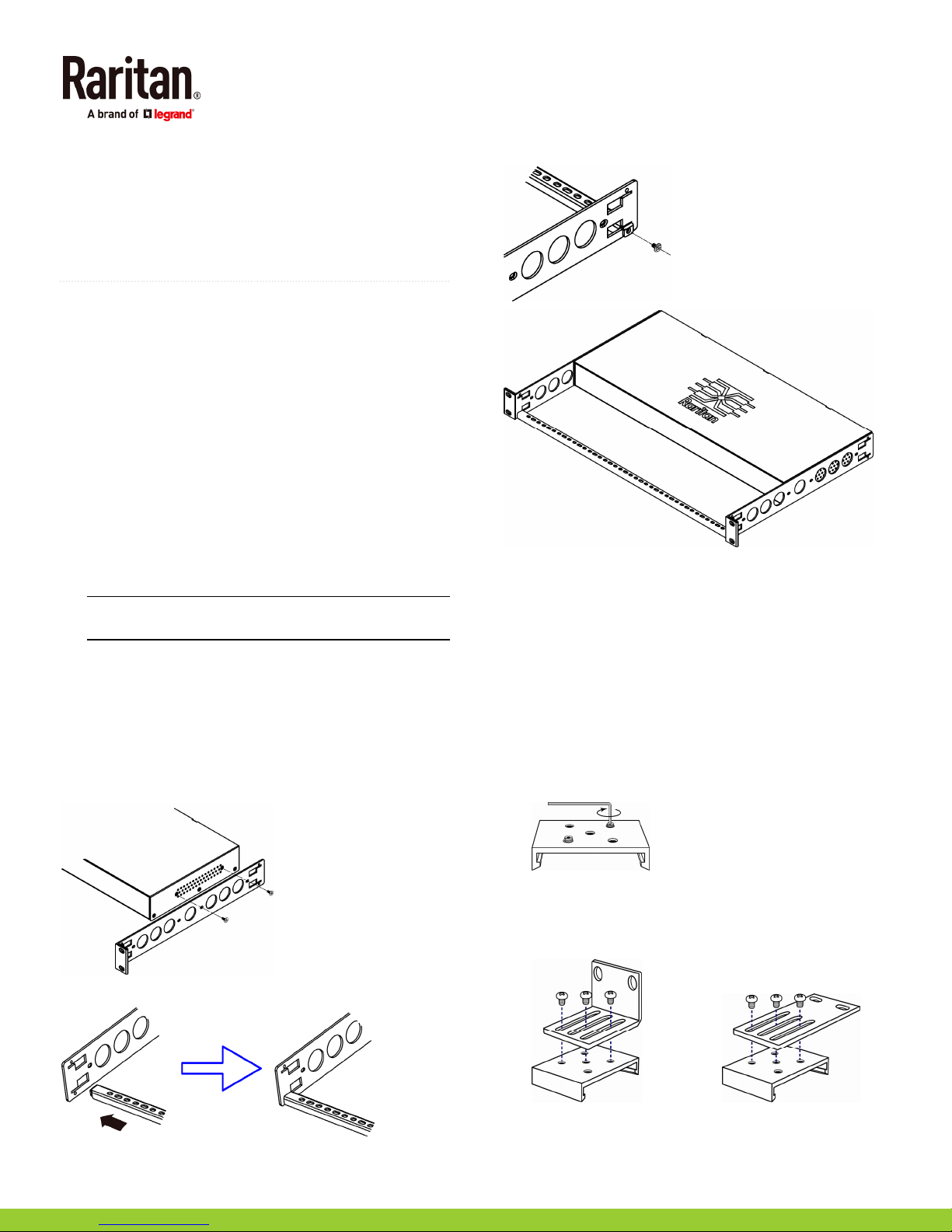
1. Attach a rackmount bracket to both sides of the PX2/PX3
with the provided screws.
3. Secure with the provided end cap screws.
4. Fasten the rackmount brackets' ears to the rack using
your own fasteners.
Mounting Zero U Models Using Baseplate-Based
Tools
You can use one of the three baseplate-based tools to mount
the PDU: L-brackets, buttons or claw-foot brackets.
To mount Zero U models using baseplates:
1. Align the baseplates on the rear of the PX2/PX3 device.
2. Make the baseplates grasp the device lightly. Use the
included L-shaped hex key to loosen the hex socket
screws until the baseplate is "slightly" fastened.
3. Attach brackets or buttons to the baseplates.
Fasten each L-bracket or claw-foot bracket to each
baseplate with at least three screws (one through each
slot).
2. Insert the cable-support bar into rackmount brackets.
OR
Raritan PX Quick Setup Guide 2
QSG-DPX2-1B-v3.3.10-E 255-80-6099-00 RoHS
Page 3
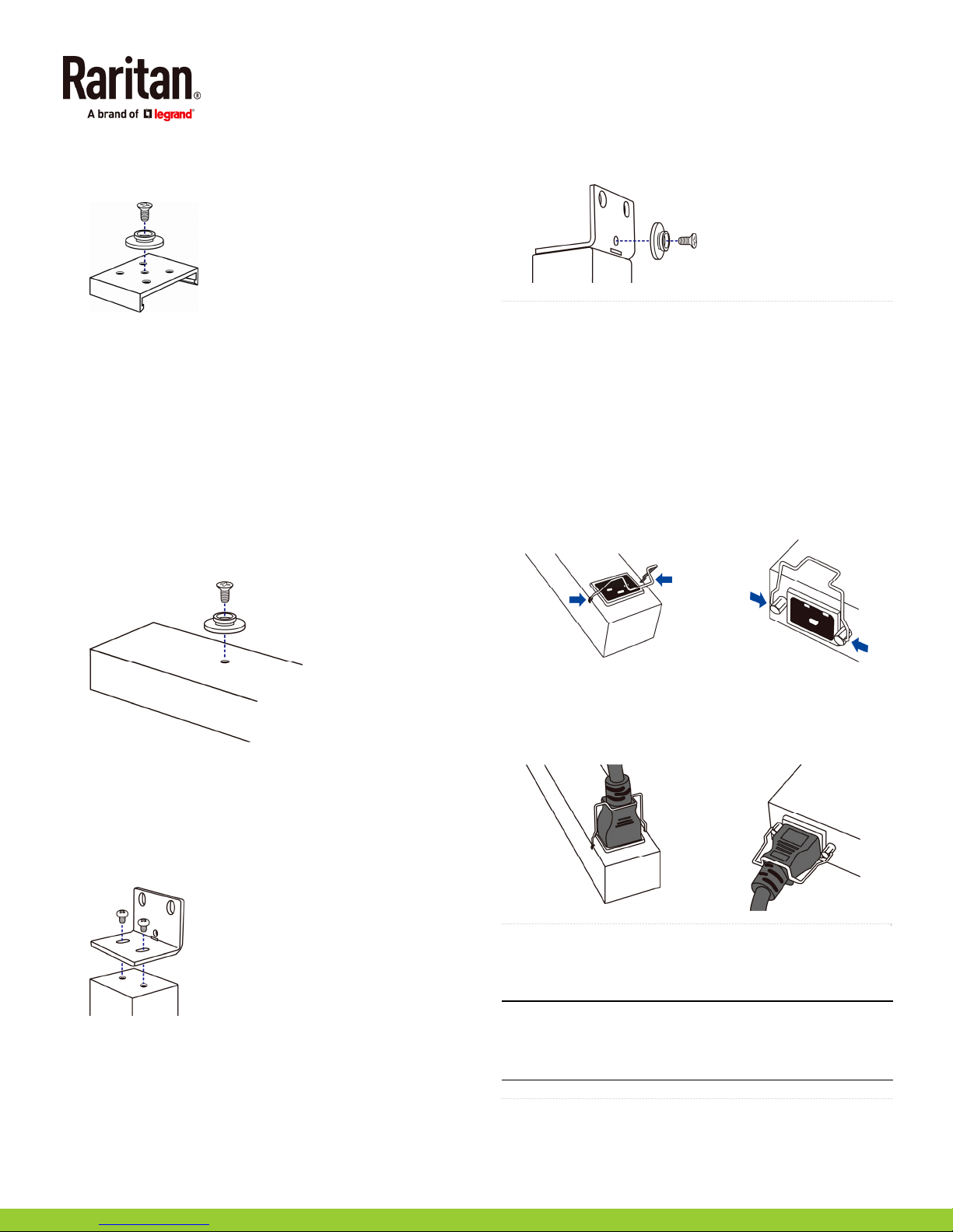
Screw each mounting button to each baseplate. The
recommended torque for the button is 1.96 N·m (20
kgf·cm).
4. Fasten the device to the rack or cabinet using the
baseplaed-based tools.
Use rack screws to fasten L-brackets or claw-foot
brackets on the PDU to the rack.
For the buttons, press the PDU forward, pushing the
mounting buttons through the mounting holes, then
letting the device drop about 5/8".
Mounting Zero U Models Using Buttons
1. Turn to the rear of the PDU.
2. Locate the two screw holes on the rear panel.
3. Screw a button in each screw hole. The recommended
torque for the button is 1.96 N·m (20 kgf·cm).
mounting holes in the rack. The recommended torque
for the button is 1.96 N·m (20 kgf·cm).
QS Rule
Installing Cable Retention Clips on the Inlet
(Optional)
If your PX2/PX3 device is designed to use a cable retention
clip, install the clip before connecting a power cord. A cable
retention clip prevents the connected power cord from
coming loose or falling off.
To install and use a cable retention clip on the inlet:
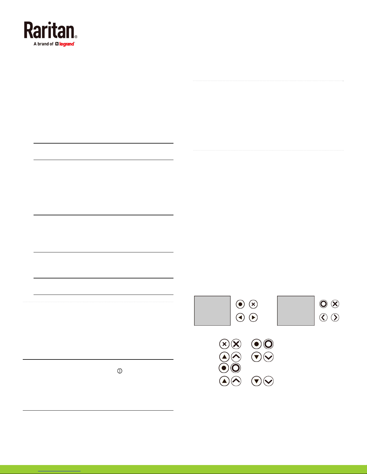
1. Install the cable retention clip by inserting two ends of the
clip into the two tiny holes adjacent to the inlet.
Zero U models 1U/2U models
4. Press the PDU forward, pushing the mounting buttons
through the mounting holes, then letting the PDU drop
slightly.
Mounting Zero U Models Using L-Brackets and
Buttons
1. Fasten the L-bracket to each end of the PDU.
2. Choose either of the following ways to fasten the PDU to
the rack.
Attach the rack screws to the two rackmount holes of
each L-bracket.
Screw a mounting button in the back center of each
L-bracket and then have both buttons engage the
2. Connect the power cord to the inlet, and press the clip to
hold the cord.
Zero U models 1U/2U models
QS Rule
Connecting the PX3 Locking Line Cord
A PX3 model is shipped with a locking line cord. Plug that cord
into the PDU's inlet and the cord is securely locked.
Note: To remove the cord, press the locking clips or push the
slide buttons at two sides of the cord's connector. For details,
see the topic titled "Disconnecting a Locking Line Cord" in the
PX3 online help.
QS Rule
Raritan PX Quick Setup Guide 3
QSG-DPX2-1B-v3.3.10-E 255-80-6099-00 RoHS
Page 4
Connecting the PDU to a Power Source
The distance between a PDU and its power source must be
SHORTER than the PDU's line cord to avoid stretching out the
cord. A locking connector used at the power source is highly
recommended for a secure connection.
To connect a PDU to the power source:
1. Verify that all circuit breakers on the PX2/PX3 device are
set to ON. If not, turn them ON.
Or make sure that all fuses are inserted and seated
properly. If there are any fuse covers, ensure that they
are closed.
Note: Not all PX2/PX3 devices have overcurrent
protection mechanisms.
2. Connect each PX2/PX3 to an appropriately rated branch
circuit. See the label or nameplate affixed to your PX2/PX3
for appropriate input ratings or range of ratings.
3. When a PX2/PX3 device powers up, it proceeds with the
power-on self test and software loading for a few
moments. At this time, the outlet LEDs cycle through
different colors.
Note: If a PDU beeps after being powered up, either its
circuit breaker has tripped or the L-N wiring is reversed.
If no circuit breakers tripped, check the wiring of the plug
adapter that is used or the direction in which the plug or
plug adapter is plugged into the power socket.
4. When the software has completed loading, the outlet LEDs
show a steady color and the front panel display
illuminates.
Note: A PX2-1000 or PX3-1000 PDU does not have outlet
LEDs so only the front panel display illuminates.
QS Rule
Connecting the PDU to Your Network
PX2/PX3 can be connected to a wired or wireless network.
To make a wired connection:
1. Connect a standard network patch cable to the ETHERNET
port on the PX2/PX3.
2. Connect the other end of the cable to your LAN.
Note: For PX3-iX7, you can connect either Ethernet port to the
LAN, but the "green" port labeled "ETH 10/100/1000" is
highly recommended because it supports 1000 Mbps. If
connecting both ports to the LAN, you must connect them to
two "different" subnets. If you are not sure whether the PDU
is connected to the same or different subnets, contact your IT
department.
To make a wireless connection:
1. Connect an appropriate USB wireless LAN adapter to the
PDU.
2. Make sure the wireless LAN configuration is supported by
your PDU. See
(on page 8).
QS Rule
Appendix B: Wireless LAN Information
Initial Network Configuration
Depending on your networking environment, the best method
to initially configure your PX2/PX3 differs.
For a DHCP IPv4 networking environment, see
Web Browser
(on page 4).
Using a
For an IPv6 or "static" IPv4 networking environment, see
Appendix A: Configuration via a Connected Computer
(on page 5).
QS Rule
Using a Web Browser
Initial configuration using a web browser involves these two
steps.
Step 1: Retrieve the IP Address
Step 2: Log in to the PX2/PX3 Web Interface
Step 1: Retrieve the IP Address
After connecting to a DHCP IPv4 network, an IPv4 address is
automatically assigned to your PX2/PX3.
A PX3 model's IP address is available using the front panel
display.
A PX2 model's IP address is available via the command line
interface (CLI).
PX3 Models
Depending on the PX3 model you purchased, the front panel
display is similar to either diagram below.
To retrieve the IP address:
1. Press
2. Press
press
3. Press
address is displayed.
/ or / to show the "Main Menu."
/ or / to select "Device Info," and
/ .
/ or / until the device's IP
PX2 Models
1. Connect PX2 to a computer via an RS-232 or USB cable.
See
Step 1: Connect the PX2/PX3 to a Computer
page 5).
(on page 4)
(on page 5)
- OR -
(on
Raritan PX Quick Setup Guide 4
QSG-DPX2-1B-v3.3.10-E 255-80-6099-00 RoHS
Page 5
2. On the computer, open a communications program with
appropriate COM port settings. See
PX2/PX3 via CLI (Optional)
(on page 6) for COM port
Step 2: Configure the
settings.
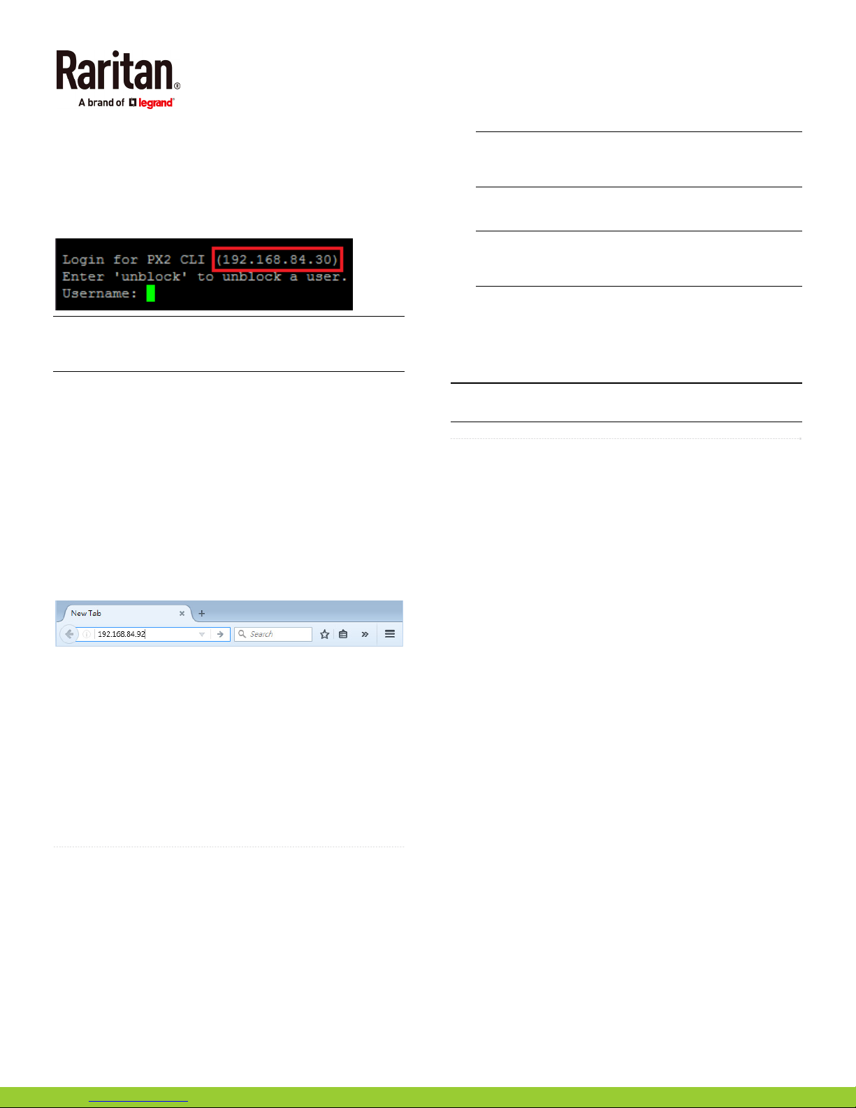
3. Press Enter in the communications program, and the IP
address is displayed onscreen as illustrated below.
Note: The DHCP-assigned IP address can be also retrieved
through the MAC address. You can contact your LAN
administrator for assistance. See
MAC Address
(on page 9).
Step 2: Log in to the PX2/PX3 Web Interface
The PX2/PX3 supports common web browsers, including
Microsoft Internet Explorer
Chrome.
To access the PX2/PX3 web interface:
1. Open a web browser and type the IP address of the
PX2/PX3 device.
If the link-local addressing has been enabled, you can
type
pdu.local
A: Configuration via a Connected Computer
5).
2. Accept any security warnings that may appear.
3. Type the default user credentials and click Login.
User name: admin
Password: raritan
4. When prompted to change the password, change or ignore
it.
To change it, type the new password and click Ok.
To ignore it for this time only, click Not Now.
To ignore it permanently, select "Do not ask again" and
click Not Now.
QS Rule
®
, Mozilla Firefox®, and Google®
instead of an IP address. See
Appendix
(on page
What To Do Next
1. Connect IT equipment to the outlet(s) on the PX2/PX3.
2. Launch the web browser if not yet. See
the PX2/PX3 Web Interface
(on page 5).
3. Choose Device Settings > Date/Time to configure the
PX2/PX3 with the proper date and time or synchronize it
with an NTP server. The PX2/PX3 device's time must be in
sync with the LDAP server to use LDAP authentication.
Step 2: Log in to
Note: If you are using Sunbird's Power IQ to manage the
PX2/PX3, you must configure Power IQ and the PX2/PX3
to have the same date/time or NTP settings.
4. To change network settings, choose Device Settings >
Network.
Tip: As of release 3.3.10, you can enable both wired and
wireless networking so that the PX2/PX3 can be accessed
via both wired and wireless IP addresses.
5. The PX2/PX3 is sent from the factory with all the outlets
ON. If your model is outlet-switching capable, turn OFF
the outlets without devices connected.
6. Use the menu to the left to configure user profiles,
privileges, security, outlet thresholds, or network settings.
Note: Detailed instructions are available in the PX2 or PX3
Online Help or User Guide.
QS Rule
Appendix A: Configuration via a Connected
Computer
To use the command line interface (CLI) for configuration,
establish an RS-232 or USB connection.
To use a web browser for configuration, make a network
connection to the computer. The PX2/PX3 is automatically
configured with the following link-local addressing in any
network without DHCP available:
https://169.254.x.x
https://pdu.local
Step 1: Connect the PX2/PX3 to a Computer
Establish one of the following connections to a computer.
Serial connection for "DB9" RS-232 connector on
PX2/PX3:
1. Connect one end of the null-modem DB9 cable to the male
"DB9" RS-232 port labeled CONSOLE / MODEM on the
PX2/PX3.
2. Connect the other end to your computer's RS-232 port
(COM).
3. Perform
(Optional)
Serial connection for "RJ-45" RS-232 connector on
PX3-iX7:
The iX7
as above except that a third party RJ-45 to "DB9 female"
adapter/cable is required, such as the blue Cisco adapter
cable. This is because the CONSOLE / MODEM port on
iX7
Step 2: Configure the PX2/PX3 via CLI
(on page 6).
™
PDU's serial connection procedure is the same
™
is a female RJ-45 connector.
(where x is a number)
Raritan PX Quick Setup Guide 5
QSG-DPX2-1B-v3.3.10-E 255-80-6099-00 RoHS
Page 6

USB connection:
®
1. A USB-to-serial driver is required in Windows
driver before connecting the USB cable. See
USB-to-Serial Driver (Optional)
(on page 8).
. Install this
Installing the
2. Connect a USB cable between the PX2/PX3 device's
USB-B port and a computer's USB-A port.
3. Perform
(Optional)
Step 2: Configure the PX2/PX3 via CLI
(on page 6).
Direct network connection:
The Ethernet port must be enabled for this connection to work
properly. Per default, the Ethernet port is enabled.
1. Connect one end of a standard network patch cable to the
ETHERNET port of the PX2/PX3.
For iX7
™
, either Ethernet port is fine.
2. Connect the other end to a computer's Ethernet port.
3. On the connected computer, launch a web browser to
access the PX2/PX3, using either link-local addressing:
pdu.local
or
169.254.x.x
. See
Using a Web Browser
(on
page 4). You CANNOT use the CLI for this connection.
Note: Make sure the c
omputer's wireless interface is
disabled.
5. If prompted to change the default password, change or
ignore it.
To change it, follow onscreen instructions to type your
new password.
To ignore it, simply press Enter.
6. The # prompt appears.
7. Type config and press Enter.
8. To configure network settings, type appropriate
commands and press Enter. Refer to the following
commands list. CLI commands are case sensitive.
9. After finishing the network settings, type apply to save
changes. To abort, type cancel.
Commands for wired networking:
The <ipvX> variable in the following commands is either
ipv4
or
ipv6
, depending on the type of IP protocol you are
configuring.
For PX2 and PX3, replace the variable <ETH> with the word
"ethernet". For PX3-iX7, replace the variable <ETH> with
either 'ETH1' or 'ETH2', depending on which Ethernet port
you are configuring.
General IP settings:
Step 2: Configure the PX2/PX3 via CLI (Optional)
You perform the following over an RS-232 or USB connection
only.
To configure the PX2/PX3 via CLI:
1. On the computer connected to the PX2/PX3, open a
communications program such as HyperTerminal or
PuTTY.
2. Select the appropriate COM port, and set the following
port settings:
Bits per second = 115200 (115.2Kbps)
Data bits = 8
Stop bits = 1
Parity = None
Flow control = None
Tip: For a USB connection, you can determine the COM
port by choosing Control Panel > System > Hardware >
Device Manager, and locating the "Dominion PX2 Serial
Console" under the Ports group.
3. In the communications program, press Enter to send a
carriage return to the PX2/PX3.
4. The PX2/PX3 prompts you to log in. Both user name and
password are case sensitive.
a. Username: admin
b. Password: raritan (or a new password if you have
changed it).
To set or
Use this command
enable
IPv4 or IPv6
protocol
IPv4
configuration
method
IPv6
configuration
method
Preferred host
name (optional)
IP address
returned by the
DNS server
Static IP configuration:
network <ipvX> interface <ETH>
enabled <option>
<option> =
network ipv4 interface <ETH>
configMethod <mode>
<mode> =
network ipv6 interface <ETH>
configMethod <mode>
<mode> =
network <ipvX> interface <ETH>
preferredHostName <name>
<name> = preferred host name
network dns resolverPreference
<resolver>
<resolver> =
true
, or
dhcp
(default) or
automatic
preferV4
false
static
(default) or
or
preferV6
static
Raritan PX Quick Setup Guide 6
QSG-DPX2-1B-v3.3.10-E 255-80-6099-00 RoHS
Page 7

a
To set Use this command
Static IPv4 or
IPv6 address
Static IPv4 or
IPv6 gateway
IPv4 or IPv6
primary DNS
server
IPv4 or IPv6
secondary DNS
server
IPv4 or IPv6
third DNS
server
Commands for wireless networking:
General wireless settings:
To set or
network <ipvX> interface <ETH>
address <ip address>
<ip address> = static IP address, with a
syntax similar to the example below.
Example:
network <ipvX> gateway <ip address>
192.168.7.9/24
<ip address> = gateway's IP address
network dns firstServer <ip
address>
<ip address> = DNS server's IP address
network dns secondServer <ip
address>
<ip address> = DNS server's IP address
network dns thirdServer <ip
address>
<ip address> = DNS server's IP address
Use this command
enable
Wireless
interface
SSID
BSSID
802.11n
protocol
Authentication
method
PSK
EAP outer
authentication
network wireless enabled <option>
true
, or
<option> =
network wireless SSID <ssid>
false
<ssid> = SSID string
network wireless BSSID <bssid>
<bssid> = AP MAC address or
network wireless enableHT <option>
<option> =
true
, or
false
network wireless authMethod
<method>
<method> =
network wireless PSK <psk>
psk
or
eap
<psk> = PSK string
network wireless
eapOuterAuthentication
<outer_auth>
<outer_auth> =
PEAP
To set or
Use this command
enable
EAP inner
authentication
EAP identity
EAP password
EAP CA
certificate
The content to be copied from the CA certificate does NOT
include the first line containing "BEGIN CERTIFICATE" and the
final line containing "END CERTIFICATE." If a certificate is
installed, configure the following:
network wireless
eapInnerAuthentication
<inner_auth>
<inner_auth> =
MSCHAPv2
network wireless eapIdentity
<identity>
<identity> = your user name for EAP
authentication
network wireless eapPassword
When prompted to enter the password for
EAP authentication, type the password.
network wireless eapCACertificate
When prompted to enter the CA certificate,
open the certificate with a text editor, copy
and paste the content into the
communications program.
Whether to Use this command
Verify the
certificate
Accept an
expired or not
valid certificate
none
Make the
connection
successful by
ignoring the
"incorrect"
system time
Wireless IPv4 / IPv6 settings:
Commands for wireless IP settings are identical to those for
wired networking. Just replace the variable <ETH> with the
word 'wireless'. The following illustrates a few examples.
network wireless
enableCertVerification <option1>
<option1> =
true
or
false
network wireless
allowOffTimeRangeCerts <option2>
true
or
false
<option2> =
network wireless
llowConnectionWithIncorrectClock
<option3>
<option3> =
true
or
false
Raritan PX Quick Setup Guide 7
QSG-DPX2-1B-v3.3.10-E 255-80-6099-00 RoHS
Page 8
To set or
Use this command
enable
IPv4
configuration
method
IPv6
configuration
method
To verify network settings:
After exiting the above configuration mode and the # prompt
re-appears, type this command to verify all network settings.
show network
QS Rule
network ipv4 interface WIRELESS
configMethod <mode>
<mode> =
dhcp
(default) or
static
network ipv6 interface WIRELESS
configMethod <mode>
<mode> =
automatic
(default) or
static
Appendix B: Wireless LAN Information
USB Wireless LAN Adapters
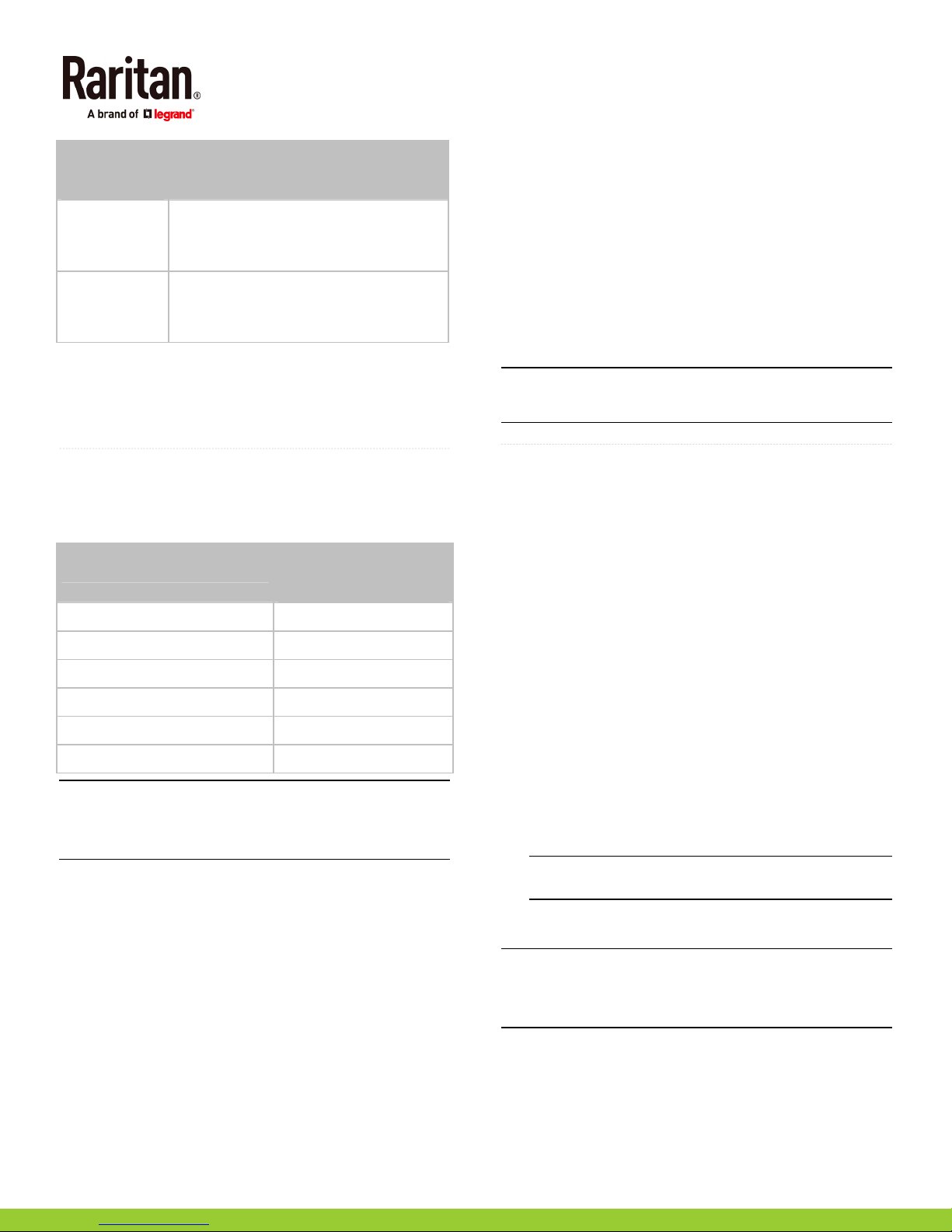
The PX2/PX3 supports the following USB Wi-Fi LAN adapters.
Wi-Fi LAN adapters Supported 802.11
protocols
SparkLAN WUBR-508N A/B/G/N
Proxim Orinoco 8494 A/B/G
Zyxel NWD271N B/G
Edimax EW-7722UnD A/B/G/N
TP-Link TL-WDN3200 v1 A/B/G/N
Raritan USB WIFI A/B/G/N
Note: To use the Edimax EW-7722UnD or Raritan USB WIFI
wireless LAN adapter to connect to an
network, the handshake timeout setting must be changed to
500 or greater, or the wireless connection will fail.
Connecting the Wireless LAN Adapter
You can connect the wireless LAN adapter either to the PDU
or to a USB hub attached to the PDU.
To make a wireless connection:
Do one of the following:
Plug a supported USB wireless LAN adapter into the
USB-A port on your PX2/PX3.
Connect a USB hub to the USB-A port on the PX2/PX3.
Then plug the supported USB wireless LAN adapter
into the appropriate USB port on the hub.
802.11n
wireless
Supported Wireless LAN Configuration
If wireless networking is preferred, ensure that the wireless
LAN configuration of your PX2/PX3 matches the access point.
The following is the wireless LAN configuration that the
PX2/PX3 supports.
Network type: 802.11 A/B/G/N
Protocol: WPA2 (RSN)
Key management: WPA-PSK, or WPA-EAP with PEAP
and MSCHAPv2 authentication
Encryption: CCMP (AES)
Important: Supported 802.11 network protocols vary
according to the wireless LAN adapter being used with the
PX2/PX3. See
QS Rule
USB Wireless LAN Adapters
(on page 8).
Appendix C: Other Information
Installing the USB-to-Serial Driver (Optional)
The PX2/PX3 can emulate a USB-to-serial converter over a
USB connection. A USB-to-serial driver named "Dominion
PX2 Serial Console" is required for Microsoft
operating systems.
Download the Windows driver for USB serial console from the
Raritan website's
(
http://www.raritan.com/support/
name is
dominion-serial-setup-<n>.exe
Support page
). The downloaded driver's
represents the file's version number.
There are two ways to install this driver: automatic and
manual installation. Automatic driver installation is highly
recommended.
Automatic driver installation in Windows
1. Make sure the PX2/PX3 is NOT connected to the computer
via a USB cable.
2. Run dominion-serial-setup-<n>.exe on the computer and
follow online instructions to install the driver.
Note: If any Windows security warning appears, accept it
to continue the installation.
3. Connect the PX2/PX3 to the computer via a USB cable. The
driver is automatically installed.
Note: Manual installation is required only if the automatic
installation fails. See the section titled "Installing the
USB-to-Serial Driver (Optional)" in the online help for manual
installation procedure.
In Linux:
No additional drivers are required, but you must provide the
name of the tty device, which can be found in the output of the
"dmesg" after connecting the PX2/PX3 to the computer.
®
Windows®
, where <n>
®
:
Raritan PX Quick Setup Guide 8
QSG-DPX2-1B-v3.3.10-E 255-80-6099-00 RoHS
Page 9
Usually the tty device is "/dev/ttyACM#" or "/dev/ttyUSB#,"
where # is an integer number.
For example, if you are using the kermit terminal program,
and the tty device is "/dev/ttyACM0," perform the following
commands:
> set line /dev/ttyACM0
> connect
MAC Address
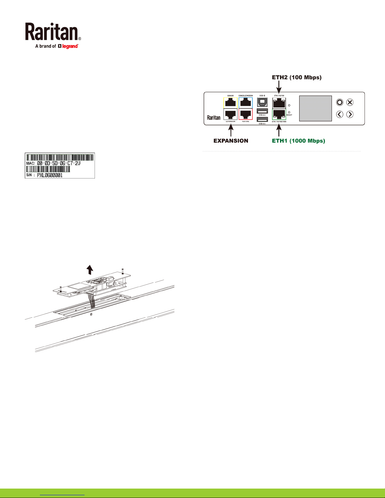
A label is affixed to the PX2/PX3, showing both the serial
number and MAC address.
If necessary, you can find its IP address through the MAC
address by using commonly-used network tools. Contact your
LAN administrator for assistance.
PX3 Replaceable Controller
The controller of a PX3 model is replaceable if it is broken.
Contact Raritan Technical Support when a replacement
controller is needed.
For detailed information on how to remove it, see the topic
titled "Replaceable Controller" in the PX3 online help.
locations on your iX7
illustration.
QS Rule
™
may look different from the following
iX7-Specific Features
PX3 with iX7™ controller supports the following significant
features, which are NOT supported by non-iX7 PX3 models.
Dual networking with two Ethernet ports (ETH1/ETH2):
Both Ethernet ports must connect to two "different"
subnets. Connection to the same subnet is NOT
recommended.
Power sharing via the EXPANSION port: Power sharing
ensures the continuous accessibility to the iX7
when a power failure occurs on its inlet.
For more information on dual Ethernet and power sharing
functionality, refer to PX3 online help or user guide. Port
Raritan PX Quick Setup Guide 9
QSG-DPX2-1B-v3.3.10-E 255-80-6099-00 RoHS
™
controller
 Loading...