

Page 1

5DULWDQ3;
6DIHW\3UHFDXWLRQV
7KUHDGHG*URXQGLQJ3RLQW
8QSDFNLQJWKH3;
Quick Setup Guide
Thank you for purchasing the Raritan PX intelligent power distribution unit (PDU). The intended use of the Raritan PX is distribution of
power to information technology equipment such as computers and communication equipment where such equipment is typically
mounted in an equipment rack located in an information technology equipment room.
This Quick Setup Guide explains how to install and configure the PX. For more information on using the PX, see Raritan PX online
help or User Guide, which is accessible from the product application, Support page (http://www.raritan.com/support/) or Product
Online Help page (http://www.raritan.com/support/online-help/). For more information on this release, see the latest release
notes on the Support page.
For the power cord installation of an inline monitor (PX-3nnn series, where nnn are numeric digits), see the Raritan PX Power Cord
Installation Guide on the Support page (http://www.raritan.com/supp
ort/).
WARNING! Read and understand all sections in this guide
before installing or operating this product. Failure to heed any
of the following WARNINGS may result in electric shock, fire,
personal injury and death. Prior to operating this product, the
user should read the online help or User Guide and
specifically the warnings in the online help or User Guide.
WARNING! Connect this product to an AC power source
whose voltage is within the range specified on the product's
nameplate.
WARNING! Connect this product to an AC power source that
is current limited by a suitably rated fuse or circuit breaker in
accordance with national and local electrical codes.
WARNING! Use this product in a dry location.
WARNING! Connect this product to a protective earth ground.
Never use a "ground lift adaptor" between the product's plug
and the wall receptacle.
WARNING! If this product is a model that requires assembly
of its line cord or plug, all such assembly must be performed
by a licensed electrician and the line cord or plugs used must
be suitably rated based on the product's nameplate ratings
and national and local electrical codes.
QS Rule
,QVWDOODWLRQ,QIRUPDWLRQ
This product must be installed by suitably qualified personnel
in accordance with the requirements of relevant legislation
and r
egulations for the region (e.g. the National Electric Code
in the USA, the Canadian Electric Code in Canada, the IEE
wiring regulations in UK, etc.) as well as accepted practices in
industry. Any information about the uses for which these
products were designed and tested is available on request.
Installation should be in accordance with any appropriate
Health & Safety regulations.
This product has been designed to conform to the latest
safety requirements. In addition to compliance with standards
for general use, this PDU has been factory configured for use
in 19” rack mounting environments. This does NOT preclude
their use in other situations.
If the PX model you purchased is designed to have a
threaded grounding point, which is usually located near the
inlet's cable gland, you can identify it via the grounding
symbol as shown below:
Wire this point to an electrical system in order to protectively
ground the PX.
QS Rule
The PX comes in Zero U, 1U, and 2U sizes. The following
describes the equipment shipped with each size. Unpack the
components. If any pieces are missing or damaged, report to
Raritan Technical Support at [email protected], or contact the
Raritan partner where you purchased the product.
Raritan PX Quick Setup Guide
QSG-DPX-0O-v1.5.13-E y 255-80-6081-00 RoHS
1
Page 2
=HUR86L]H
8DQG86L]H
%HIRUH<RX%HJLQ
0RXQWLQJWKH3;
&LUFXLW%UHDNHU2ULHQWDWLRQ/LPLWDWLRQ
0RXQWLQJ8RU80RGHOV
0RXQWLQJ=HUR80RGHOV8VLQJ/%UDFNHWV
x The PX device
x Tool-less mounting bracket and bracket with screws
x Null modem cable with RJ-45 and DB9F connectors
x Quick Setup Guide
x Warranty card
x The PX device
x 1U or 2U bracket pack and screws
x Null modem cable with RJ-45 and DB9F connectors
x Quick Setup Guide
x Warranty card
QS Rule
1. Prepare the installation site. Make sure the installation
area is clean and not exposed to extreme temperatures or
humidity. Allow sufficient space around the device for
cabling and outlet connections. Safety instructions are
provided in the PX online help or User Guide.
2. Fill out the Equipment Setup Worksheet found in the PX
online help or User Guide. Record the model, serial
number, and use of each IT device connected to the PX.
QS Rule
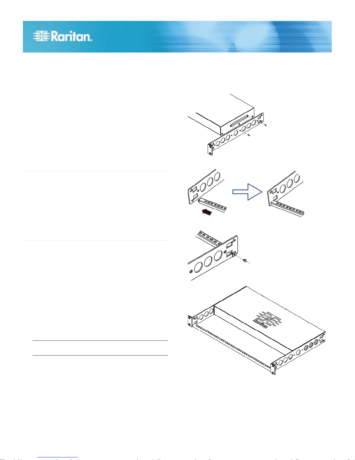
1. Attach two rackmount brackets to both sides of the PX
with the provided screws.
2. Insert the cable-support bar into rackmount brackets.
3. Secure with the provided end cap screws.
Usually a PDU can be mounted in any orientation. However,
when mounting a PDU with circuit breakers, you must obey
these rules:
x Circuit breakers CANNOT face down. For example, do not
horizontally mount a Zero U PDU with circuit breakers on
the ceiling.
x If a rack is subject to shock in environments such as boats
or airplanes, the PDU CANNOT be mounted upside down.
If installed upside down, shock stress reduces the trip
point by 10%.
Note: If normally the line cord is down, upside down
means the line cord is up.
4. Fasten the rackmount brackets' ears to the rack using your
own fasteners.
1. Align the baseplates on the rear of the PX.
Raritan PX Quick Setup Guide
QSG-DPX-0O-v
1.5.13-E y 255-80-6081-00 RoHS
2
Page 3
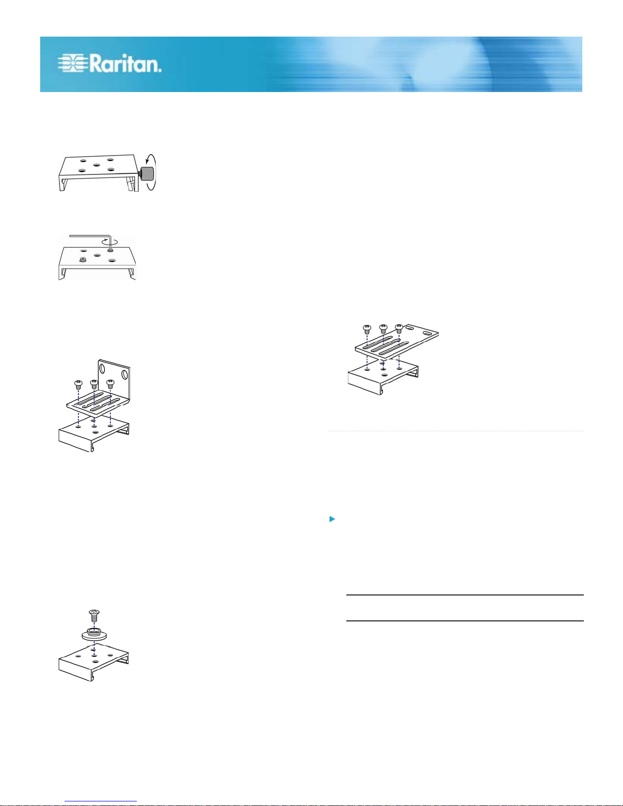
2. Secure the baseplates in place. Different models ship with
0RXQWLQJ=HUR80RGHOV8VLQJ%XWWRQ0RXQW
0RXQWLQJ=HUR80RGHOV8VLQJ&ODZ)RRW%UDFNHWV
&RQQHFWLQJWKH3;WRD3RZHU6RXUFH
7RFRQQHFWD3'8WRWKHSRZHUVRXUFH
different types of baseplates.
To secure a baseplate with the thumbscrew, turn the
thumbscrew until it is tightened.
To secure a baseplate WITHOUT the thumbscrew, use
the included L-shaped hex key to loosen the hex
socket screws until the baseplate is fastened.
3. Align the L-brackets with the baseplates so that the five
screw-holes on the baseplates line up through the
L-bracket's slots. The rackmount side of brackets should
face either the left or right side of the PX.
4. Fasten the brackets in place with at least three screws
(one through each slot). Use additional screws as desired.
6. Ensure that both buttons can engage their mounting holes
simultaneously.
7. Press the PX device forward, pushing the mounting
buttons through the mounting holes, then letting the device
drop about 5/8". This secures the PX in place and
completes the installation.
1. Align the baseplates on the rear of the PX device.
2. Secure the baseplates in place. For details, see step 2 in
the procedure: Mounting Zero U Models Using
L-Brackets (on page 2).
3. Align the claw-foot brackets with the baseplates so that
the five screw-holes on the baseplates line up through the
bracket's slots. The rackmount side of brackets should
face either the left or right side of the PX.
4. Fasten the brackets in place with at least three screws
(one through each slot). Use additional screws as desired.
5. Using rack screws, fasten the PX to the rack through the
L-brackets.
1. Align the baseplates on the rear of the PX device. Leave
at least 24 inches between the baseplates for stability.
2. Make the baseplates grasp the PX device lightly. For
details, see step 2 in the procedure: Mounting Zero U
Models Using L-Brackets (on page 2).
Screw each mounting button in the center of each
3.
baseplate. The recommended torque is 1.96 N·m (20
kgf·cm).
4. Align the large mounting buttons with the mounting holes
in the cabinet, fixing one in place and adjusting the other.
5. Depending on the type of your baseplates, either further
tighten the thumbscrews or loosen the hex socket screws
until the mounting buttons are secured in their position.
5. Using rack screws, fasten the PX to the rack through the
claw-foot brackets.
QS Rule
The distance between a PDU and its power source must be
SHORTER than the PDU's line cord to avoid stretching out
the cord. A locking connector used at the power source is
highly recommended for a secure connection.
1. Verify that all circuit breakers on the PX are set to ON. If
not, turn them ON.
Or make sure that all fuses are inserted and seated
properly. If there are any fuse covers, ensure that they
are closed.
Note: Not all PX devices have overcurrent protection
mechanisms.
2. Connect each PX to an appropriately rated branch circuit.
See the label or nameplate affixed to your PX for
appropriate input ratings or range of ratings.
3. With a 1U or 2U model, a blue power LED on the front
panel is lit. A Zero U model does not have a similar power
LED because it will be mounted in the back of a rack.
4. When a PX device powers up, it proceeds with the
power-on self test and software loading for a few
moments. At this time, the outlet LEDs cycle through
different colors.
Raritan PX Quick Setup Guide
QSG-DPX-0O-v
1.5.13-E y 255-80-6081-00 RoHS
3
Page 4

Note: If a PDU beeps after being powered up, either its
&RQQHFWLQJWKH3;WR<RXU1HWZRUN
,QLWLDO&RQILJXUDWLRQ
67(3&RQQHFWWKH3;WRD&RPSXWHU
67(3&RQILJXUHWKH3;
circuit breaker has tripped or the L-N wiring is reversed. If
no circuit breakers tripped, check the wiring of the plug
adapter that is used or the direction in which the plug or
plug adapter is plugged into the power socket.
5. When the software has completed loading, the outlet
LEDs show a steady color and the front panel display
illuminates.
Rule
QS
1. Connect a standard network patch cable to the LAN port
on the PX device.
2. Connect the other end of the cable to your LAN.
QS Rule
There are two ways to configure the PX for the first time.
x Connect the PX to a computer to configure it.
STEP 1: Connect the PX to a Computer (on page 4)
STEP 2: Configure the PX (on page 4)
x Connect the PX to a TCP/IP network that supports DHCP,
and use the IPv4 address and web browser to configure
the PX.
The DHCP-assigned IP address can be retrieved through
the PX device's MAC address. Contact your LAN
administrator for assistance. See MAC Address (on page
5).
1. Connect the RJ-45 end of the null modem cable to the port
labeled SERIAL on the PX.
2. Connect the DB9 end of the null modem cable to the serial
port (COM) of the computer.
1. On the computer connected to the PX, open a
communications program such as HyperTerminal or
PuTTY.
2. Select the appropriate COM port, and set the following
port settings:
Bits per second = 9600
Data bits = 8
Stop bits = 1
Parity = None
Flow control = None
3. In the communications program, press Enter and the
opening prompt appears.
4. Type config and press Enter.
5. The PX prompts you to assign a device name to the PDU.
Type the name and press Enter.
6. The PX prompts you to enter several networking
parameters.
The default IP configuration method is
IP
address
DHCP. To assign the PX an IP address,
choose either:
Auto configuration: Type dhcp or
bootp to let the DHCP or BOOTP
server provide the IP address.
Static IP address: Type none and
when prompted, enter an IP address,
network mask and gateway.
Leave it disabled now. It disables the PX
IP access
control
device's firewall. You can enable the firewall
and create access control rules after the
initial configuration is complete.
Leave the default auto, or type 10 or 100 for
LAN
10 or 100 Mbps.
interface
speed
LAN
Leave the default auto, or type half or full for
half or full duplex.
interface
duplex
mode
FIPS
mode
SNMP
Leave the default no to disable the FIPS
mode or type yes to enable it. Note that the
FIPS mode only supports FIPS approved
algorithms that are defined in FIPS PUB
140-2 (http://www.nist.gov/cmvp/).
Leave the default yes, or type no to disable
the SNMP agent implemented on the PX.
agent
SNMP
v1/v2c
protocol
This setting appears only when the SNMP
agent is enabled.
Leave the default yes, or type no to disable
SNMP v1/v2c. If enabled, specify the read
and write community strings when
prompted.
Default community strings include:
Read: raritan_public
Write: raritan_private
In the FIPS mode, SNMP v1/v2c is NOT
supported so the system does not prompt
you to configure it.
Raritan PX Quick Setup Guide
QSG-DPX-0O-v
1.5.13-E y 255-80-6081-00 RoHS
4
Page 5
SNMP v3
0$&$GGUHVV
:KDW7R'R1H[W
$GGLWLRQDO,QIRUPDWLRQ
protocol
agent is enabled.
Leave the default no, or type yes to enable
SNMP v3. If enabled, determine whether to
force the SNMP v3 encryption when
prompted.
In the FIPS mode, the SNMP v3 encryption
is forced automatically if enabling SNMP v3
so the system does not prompt you to
configure the SNMP v3 encryption.
7. When the SNMP agent is enabled, the PX prompts you to
specify the system location and contact person regardless
of the SNMP protocol settings. Type appropriate values for
these settings.
This setting appears only when the SNMP
The PX prompts you to configure the NTP settings for the
8.
date and time. To use LDAP authentication, the PDU's
time must be in sync with the LDAP server.
There are two options to configure the date
NTP
enabled
or
disabled
and time.
NTP synchronization: Type y to have
the date and time sync up with the
NTP server(s).
Manual configuration: Type n to
disable the synchronization with NTP
servers. Later you can log in to the
PX web interface for setting the date
and time manually.
If enabling the NTP synchronization, a list of
Time
zone
time zones is displayed for you to select.
Type the number or the name of the desired
time zone.
If enabling the NTP synchronization, the
Daylight
savings
time
system prompts you to set the daylight
savings time. When the daylight savings
time applies to the selected time zone, type
yes to enable it. Otherwise, type no to
disable it.
For NTP synchronization, there are two
NTP
server
settings
ways to specify NTP servers.
DHCP- or BOOTP-assigned NTP
server(s): Type yes, and the PX will
sync up with the NTP server(s)
provided by the DHCP or BOOTP
server.
Manually-specified NTP servers:
Type no and then configure the
primary and secondary NTP servers
when prompted.
9. After entering all information, you are asked to confirm the
values you entered. If any are incorrect, type n, press
Enter, and go back to change them. When they are
correct, type y and press Enter.
Note: The default static IP address is 192.168.0.192. The
default IP configuration method is DHCP. The default IP
address will be replaced by the address assigned by DHCP or
BOOTP, or the static IP address you entered, when the
configuration process is complete. To use the factory default
IP address, type none at the IP auto configuration prompt.
Installation and configuration are complete.
Important: Wait at least 3 minutes for the IP address
configuration to take effect.
QS Rule
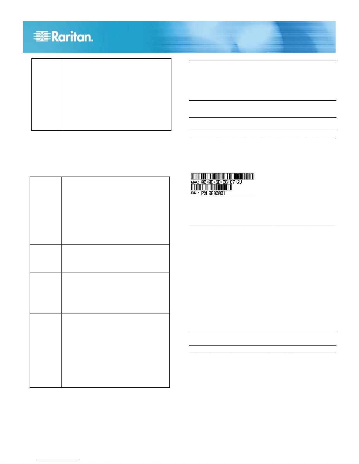
A label is affixed to the PX, showing both the serial number
and MAC address.
You can fin
d the IP address of the PX through the MAC
address by using commonly-used network tools. Contact your
LAN administrator for assistance.
QS Rule
1. Connect IT equipment to the PX outlet(s).
2. From a computer connected to your LAN, open a web
browser and type the IP address of your PX.
3. Enter admin and raritan when prompted for a user name
and password.
4. You will be prompted to change the admin password. After
changing the password, the PX page opens.
5. The PX is sent from the factory with all outlets turned ON.
If your model is outlet-switching capable, turn OFF the
outlets without any devices connected from the web
interface.
6. Use the menu at the top to create user profiles, set
privileges, set security, and configure outlet thresholds.
Note: Detailed instructions are available in the PX online help
or User Guide.
QS Rule
For more information about PX and the entire Raritan product
line, see Raritan's website (www.raritan.com). For technical
issues, contact Raritan Technical Support. See the Contact
Support page in the Support section on Raritan's website for
technical support contact information worldwide.
Raritan's products use code licensed under the GPL and LGPL. You can
request a copy of the open source code. For details, see the Open Source
Software Statement at
(http://www.raritan.com/about/legal-statements/open-source-software-statement
/) on Raritan's website.
Raritan PX Quick Setup Guide
QSG-DPX-0O-v
1.5.13-E y 255-80-6081-00 RoHS
5
 Loading...