

Page 1
PURASAN
OPERATION, MAINTENANCE AND INSTALLATION INSTRUCTIONS
(Models PST*EX [*specify 12,24] Manufactured after December 2013)
THE FOLLOWING ARE CAUTIONARY STATEMENTS THAT MUST BE READ AND
FOLLOWED DURING BOTH INSTALLATION AND OPERATION
WARNING: RaritanEngineeringCompany,Inc.recommendsthataqualiedpersonorelectricianinstallthisproduct.
Equipment damage, injury to personnel or death could result from improper installation. Raritan Engineering
Company, Inc. accepts no responsibility or liability for damage to equipment, or injury or death to personnel
that may result from improper installation or operation of this product.
WARNING: HAZARD OF SHOCK AND FIRE
Always use recommended fuse or circuit breaker and wire size.
WARNING: HAZARD OF FLOODING - When leaving the boat unattended always be sure seacocks are closed. Any
installation made below waterline should have double hose clamps securing lines. The halogen disinfectant
is corrosive to aluminum, copper and steel. The plumbing system must not include any aluminum,
copper or steel ttings, piping or holding tanks.
IMPORTANT SAFETY INSTRUCTIONS FOR HANDLING PURASAN® TABLETS AND SOLUTION
WARNING:
PURASAN® EX disinfecting tablets are a strong oxidizing agent and highly corrosive. Use or contact
with oil, acids, petroleum products, reducing agents or other chlorine compounds such as swimming
pool tablets, is extremely dangerous
WARNING:
Fire or explosion could result. Improper use of this tablet may cause personal injury or property damage.
Tablets may be fatal if swallowed and tablet dust is irritating to the eyes, nose and throat. Keep out of
reach of children and do not allow tablets or solution of tablets to contact skin, eyes or clothing. Handle
and store tablets as per instructions provided with packaging. Contact Raritan if handling instructions
are missing. Store only in sealed original container in well-ventilated area. Read tablet container label
carefully prior to use. It is unsafe and violation of Federal law to use tablets in a manner inconsistent
with its labeling.
EX Hold n’ Treat
®
The PURASAN®EX is a U. S. Coast Guard Certied Type I Marine Sanitation Device for use on un-
inspected vessels 65 feet and under. It must be operated within navigable waters inside the three mile
limit that are not declared Federal No Discharge Zones (NDZ) by the U.S. Environmental Protection
Agency (EPA). Other countries - check with local authorities.
The PURASAN®EX is designed for recreational use and accommodates most marine toilets. The
PURASAN®EX is available in 12 or 24 VDC.
DESCRIPTION:
Each time the transfer pump cycles an equal amount of previously treated waste is discharged. The pumping action of the transfer pump moves the waste through the PURASAN®EX and out.
Water is diverted to the Tablet Dispenser during the treatment cycle, creating a halogen solution during
hold time. After the hold time, the Drain Manifold and Air Pump turn on and the solution drains into the
Treatment Unit.The rst chamber macerates to reduce particle size and uniformly mix the waste with
injected halogen solution. The second chamber mixes to ensure uniform treatment of its contents.
The Hold n’ Treat is designed to integrate both a Type I and Type III MSD (Marine Sanitation Device)
to provide the user with a system that will be legal in all areas.
All waste is stored in a holding tank and the treatment mode will determine how the waste is processed.
This system eliminates the need for pump-out stations in most areas.
L519 _0815jlc
1
Page 2
TREAT/NO DISCHARGE MODE;
Press no discharge button on panel once to toggle
mode from treat to no discharge.
If position sensing shutoff valve is installed
close valve to set no discharge mode
Open Valve and press treat/no discharge button on
panel to set treat mode.
If key switch panel is installed, turn key switch to
no discharge to set no discharge mode.
Turn key to treat position and press treat /no discarge button on panel to set treat mode.
Note: Pause at least 10 seonds after mode is
switched to switch again.
Basic Operation:
OPERATION
When the Hold n’ Treat System is in treatment
mode and level in holding tank is above the LOW
LEVEL, treatment cycle starts. Macerator pump
is activated and moves approximately 1 gallon of
waste from the holding tank to the treatment tank.
Treatment cycles runs for 2 minutes.At the end of
the cycle , system waits in treatment mode for 8
seconds and cycle is repeated until the level in the
tank falls below the LOW LEVEL. If the LOW
LEVEL is not reached after ten cycles, the system
will enter into a COOL DOWN mode for ten minutes. When the system is set to NO DISCHARGE,
waste will enter the holding tank and will not be
treated until set to treatment mode.
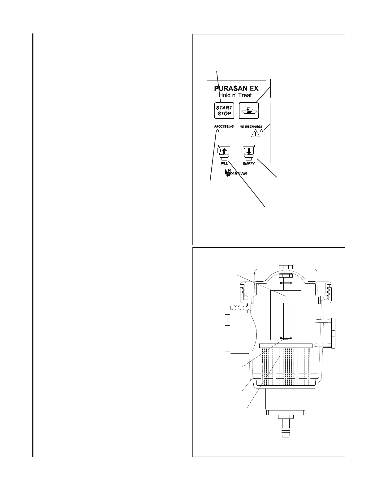
PROCESSING LED:
• blinks twice per second when unit is in treatment
cycle.
• blinks every 3 second if unit is in treat mode
and holding tank level is below LOW level or
in between treatment cycle
• blinks twice per seconds with error LED when
holding tank level is above HIGH level.
No discharge LED:
• blinks every 4 seconds when in no discharge
mode
• blinks twice per seconds when tablet dispenser
needs to checked for tablets or water level.
• on solid when motor fuse is blown
START/STOP BUTTON: Press start button to
start a cycle during treat mode to process holding
tank below LOW level. DO NOT RUN MACERATOR PUMP DRY.
Note: There is 8 seconds pause between cycles.
SWITCH PANEL
Manual Start/Stop
Disabled for no discharge mode
Treatment LED:
Flashing(1/4 sec):
Treatment cycle
Flashing (3 sec):
Treat mode
Both LED ashing:
Tank full level
Overfill
Sensor
Low Tablet
Sensor
Water Line
Tablet Holder
TABLET DISPENSER
2
Fill:
Activates Water Valve and
lls Tablet Dispenser
momentarily
FIG 2
Press to switch between
Treat and No Discharge
mode
Error/No discharge LED:
Flashing (every 1/4 sec):
Check tablet cartridge
Solid:
Check motor fuse
Flashing(every 4 sec):
No discharge mode
Empty:
Activates Drain
Manifold and Air
Pump momentarily
FIG 3
L519 _0815jlc
Page 3
OPERATION NOTES:
1. If start/stop button is pressed during rst 20 seconds of
treatment cycle, motor will stop, A drain cycle will start to
empty out and water in the dispenser before stopping the
cycle. If waste level is higher than the low level sensor , next
cycle will start immediately.
2. A cycle can be terminated by pressing NO discharge mode
button. A drain cycle will run to empty out water in the tablet
before terminating cycle. Cycle will not restart until mode
is changed to treatment mode and Level is higher than low
level.
3. If cycle completes normal, there is a 8 second pause before
next cycle will start. During this pause none of the buttons
except No Discharge mode button is functional.
MAINTENANCE
Use ONLY PURASAN® Tablets.
DO NOT add any other chemicals or cleaning products to the
toilet or the treatment system. Raritan C.P. (part # 1PCP22) Cleans Potties is the only factory-recognized cleaning product
that may be used in the toilet.
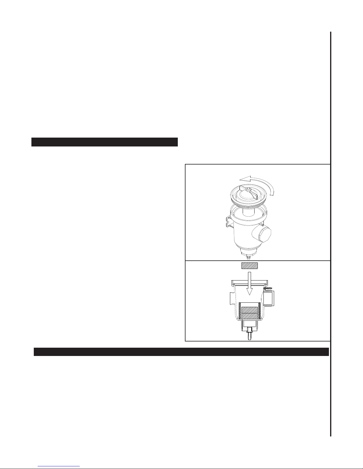
REFILLING TABLET CARTRIDGE
(#41-135A)
When Error LED is ashing it is an indication tablets in the
dispenser are depleted to less than one tablet and rell is
needed.
Press No discharge button to stop cycling.
1 Remove all water by pressing “empty” button on the
panel before opening lid.
2. Turn off power.
3. With adequate ventilation available, unscrew tablet
dispenser lid.
4. Reload with two tablets into the cartridge.
5. Replace lid on Tablet Dispenser.
6. Turn on power
7. Press NO DISCHARGE mode button to return to
treatment mode
CLEANING: Do not add any other chemicals or cleaning
products to the toilet or the treatment system.
CLEANING OF TANK CHECK VALVE(41-156)
AND ½” HOSE
A. Every 50 cycles, clean ½” hose and check valve
(41-156) on tank using following procedure:
1. Press ll button till water lls up entire ½”
hose just below tablet dispenser
2. Press and hold “empty” button until all hoses up to
check valve on treatment tank are empty.
3. Repeat steps 1&2 three more times.
B. Every time tablets are relled, check valve assembly on the
treatment tank must be cleaned.
1. Close seacocks
2. Close hose clamp completely. Remove check valve
assembly and thoroughly clean assembly with warm
water. Make sure check valve plunger is moving by
actuating with a paper clip. If check valve is stuck, replace.
REFILLING TABLETS
Insert Tablet
2 Tablets Only
OPERATION
INITIAL START-UP - AFTER ALL INSTALLATION STEPS ARE COMPLETE
CAUTION: Do not load tablets into Tablet Dispenser until
Steps 1-6 are completed.
1. Remove crossover cap (see FIG 12; #25) from Treatment
Unit tower. Pour 3 gallons (11.5 liters) of water into treatment unit. Replace crossover cap.
2. Turn on water to the Water Valve.
3. Turn on power to unit.
4. Priming: Press and hold “FILL” button until water reaches
to the water line on the Tablet Dispenser. Press and hold
“EMPTY” button until Tablet Dispenser and 3/8” tube
to Treatment Unit is empty.
L519 _0815jlc
FIG 4
5. Operate the system. Check water level in the cartridge and
make sure water is rising to the mark. If starting for rst
time or if water does not rise to the mark, see instruction
in Programming section to adjust timing.
6. Check for leaks.
7. Load the Tablet ( see relling tablet section).
3
Page 4

WINTERIZATION
IMPORTANT:
Improper winter lay up is a major cause of failure.
WARNING:
Do not use anti-freeze of any kind to winterize
the PURASAN EX system.
Treatment Unit and Tablet Dispenser
1. Turn off water supply to the toilet and ush
toilet as dry as possible.
Note: Check toilet manufacturer’s instructions
to ensure no damage is done to any components.
2. Activate PURASAN EX several times using
start/stop button to empty holding tank.
3. If drain or ushing ttings are installed in
WINTERIZATION
plumbing, Flush entire system with fresh
water.
4. Shut off water valve feeding Control Module.
5. Press EMPTY button to drain out all water
from Tablet Dispenser and tubing.
6. Turn off power and disconnect wires from
Purasan EX Control Module.
7. Remove water connection to Control Module and drain tube.
8. Close seacocks.
Recommissioning
IMPORTANT:
• Do not open shut-off valve feeding control module
until Treatment Tank is full.
• Do not operate PURASAN®EX until Treatment
Unit is lled with water.
Treatment Tank
1. Reconnect waste hoses and open seacocks.
2. Reconnect wires to control module
NOTE: Purasan Treatment Unit must be full before
activating a cycle.
3. Fill the Treatment Unit: Remove crossover plug
from Treatment Unit and ll with a minimum of
three gallons of water. Replace crossover plug and
o-ring.
4. Turn on power
5. Open water valve feeding control module.
6. Priming: Press and hold “FILL” button until water
reaches to the water line on the Tablet Dispenser.
Press and hold “EMPTY” button until
Tablet Dispenser and 3/8” tube to Treatment Unit
is empty.
7. Operate the system. Check water level in the cartridge and make sure water is rising to the mark.
If starting for rst time or if water does not rise to
the mark, see instruction in Programming section
to adjust timing.
8. Check for leaks.
9. Slowly open crossover plug (#25 page 12)
Caution: If Treatment Unit is the lowest part of
the system, water will spill out. Review plumbing carefully before slowly opening plug.
10. Using a pump and 3/8” tube, remove water
from each side of partition in Treatment Unit
through crossover plug.
11. Disconnect and drain waste hoses.
12. Proceed to toilet winterization by following
instructions for that particular toilet.
Winterizing the Toilet - Follow the instructions
in the Owner’s Manual for that particular toilet.
ANTIFREEZE WARNING -
If Antifreeze is used to winterize toilet, it must be
removed prior to connecting hoses to the Treatment
Tank. It MUST not pass through the Treatment Unit.
Winterization of Holding tank
Use anti-freeze only if there is a way to pump out
contents of holding tank without ushing into purasan
treatment tank during recommissioning, else drain or
pump out contents of the tank.
4
L519 _0815jlc
Page 5
U.S.C.G. Type I MSD Certication #159.015/0010133/0 (12V) 159.015/0010134/0 (24V)
Maximum Roll/Pitch Angle: 30°
Maximum Temperature Exposure: 120° F (49° C)
Maximum Total Flush Volume: 1.5 gallons/ush (5.7 liters/ush)
Water - fresh, salt or brackish Approximate Number of cycles per tablet--50
Hold n Treat capacity: 6 gallons (23 liters) per hour , 140 Gallon( 530 Liters) per day
NOTES: for Wiring
1. Distances are from source to unit and back to source
2. Recommended conductor wire minimum AWG (mm) for 3% voltage drop.
3. Recommended conductor sizes are based on 105oC rated insulation. Refer to
ABYC standards for other insulation ratings.
Recommended Wire and Fuse/Circuit Breaker Size with macerator pump
Units
Volt-
age
Circuit
Breaker/Fuse
sizes(AMPS)
Amp.
draw @
nominal
voltage
Macerator
amps @
nominal
voltage
10
Feet
20
Feet
30
Feet
40
Feet
50
Feet
12V 30 10 17 8AW G 6AWG 6AW G 6AWG 4AWG
24V 20 8 9 14AW G 12AW G 10AWG 10AW G 8AW G
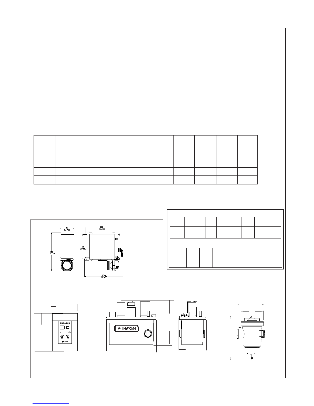
SPECIFICATIONS
Fuse Specications:
Fuse F1 for Motors (12V and 24V) Located in
the SPC Control Box:
ATO 10 AMPS, Maxi blade type.
CONTROL
MODULE
SWITCH PANEL
DIMENSIONS
3 1/4”
(8.3 cm)
4 3/4”
(12 cm)
TREATMENT UNIT DIMENSIONS
Width:
16” (40.6cm)
CONVERSIONS
Wire - AWG to mm
AWG 16 14 12 10 8 6 4 2
mm21.5 2.5 4.0 6.0 10.0 16.0 25.0 35.0
Feet to Meters
Feet 10 15 20 25 30 40 50
Meter 3.1 4.6 6.1 7.6 9.2 12.2 15.2
TABLET DISPENSER
Height:
13 ½”
(34.3cm)
11
[291]
Depth:
8 ¾” (22.3cm)
2
DIMENSIONS
1
7
4
[184]
6
[152]
1
2
L519 _0815jlc
5
Page 6
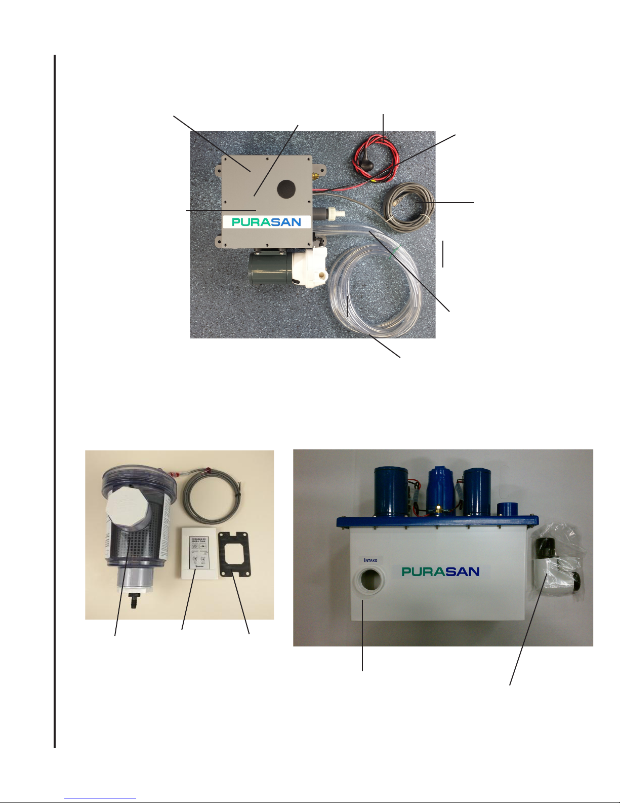
Parts Included in the Box:
Control Module
Air Pump
Inside the module:
Drain Manifold
Water Valve
SPC control box
6’ black and red
wire to connect
transfer pump
6’ black and orange
wire to connect tank
SensaLevel
sensor with
cable
16’ of Cable to
Connect Switch
Panel to Control
Box
INSTALLATION
For Treatment unit:
6’ 3/8” ID tubing
For Dispenser:
6’ 1/4” ID tubing
6’ 3/8” ID tubing
Switch Panel
Tablet
Dispenser
Switch Panel
Gasket
Treatment unit
6
Fittings for
Treatment
Unit
L519 _0815jlc
Page 7
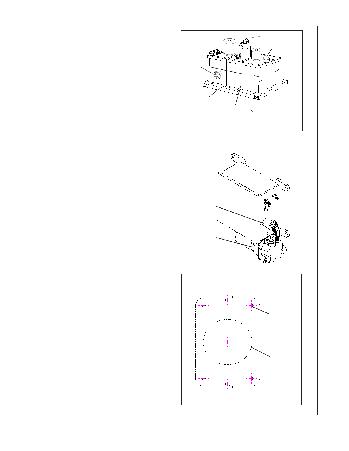
LOCATION AND MOUNTING
Treatment Unit:
WARNING: Do not locate in an area where ambient
temperature exceeds 120o F (49o C).
1. Locate top of treatment tank at or below
discharge of toilet and within six feet (1.5 m)
of toilet.
Note: Longer runs require additional ush time to
avoid sewage laying in the hose.
Note: If mounting treatment tank higher than
discharge, a vented loop must be used between
toilet and Treatment Unit.
2. Make and secure mounting frame to flat
surface. (FIG 5)
3. Secure tank to frame using 3/4” (1.9 cm)
mounting straps.
Note: Placing a 3/8” (.9 cm) rubber pad under tank
will help to reduce vibration and noise.
Control Module :
Note: Wires supplied are 6 feet between tank and
control module
1. Locate control module between Tablet Dis-
penser and Treatment Unit. Vertical mounting is
recommended (FIG 6)
2. Using screws secure manifold to the wall (FIG 6)
Switch Panel: Cable Supplied is 16 feet
FIG 5
INTAKE
1” (2.5cm)
Mounting Frame*
FIG 6
Water valve
Air pump
14 1/8”
(35.9cm)
Mounting
Straps - not included
Treatment Unit Mounting
Control Module
Crossover Plug
DISCHARGE
7”
(17.8 cm)
1” (2.5cm)
INSTALLATION
1. Locate in head compartment where indicator
lights will be visible.
2. Using base plate, mark the cutout for the panel.
(See FIG 7)
3. Route cable between switch panel and
PURASAN®EX Control module.
4. Attach cable to back of switch panel.
5. After wiring and testing entire system:
Mount panel using 4 screws. Apply a bead of
nonpermanent sealant around rear edges of
panel if located in shower area.
PURASAN®EX Tablet Dispenser
1. Locate tablet dispenser in a location where
rell of tablet is convenient. (To easily remove
lid and rell tablets a clearance of 8” from top
of lid is recommended.)
2. Attach to wall or suitable structure using 1/4”
(6 mm) bolts.
NOTE: Do Not load tablets into Tablet Dispenser
at this time. Load tablets after completing start
up procedure.
L519 _0815jlc
7
FIG 7
Size for panel
5/64” (2 MM)
2 1/4” (57mm)
Page 8
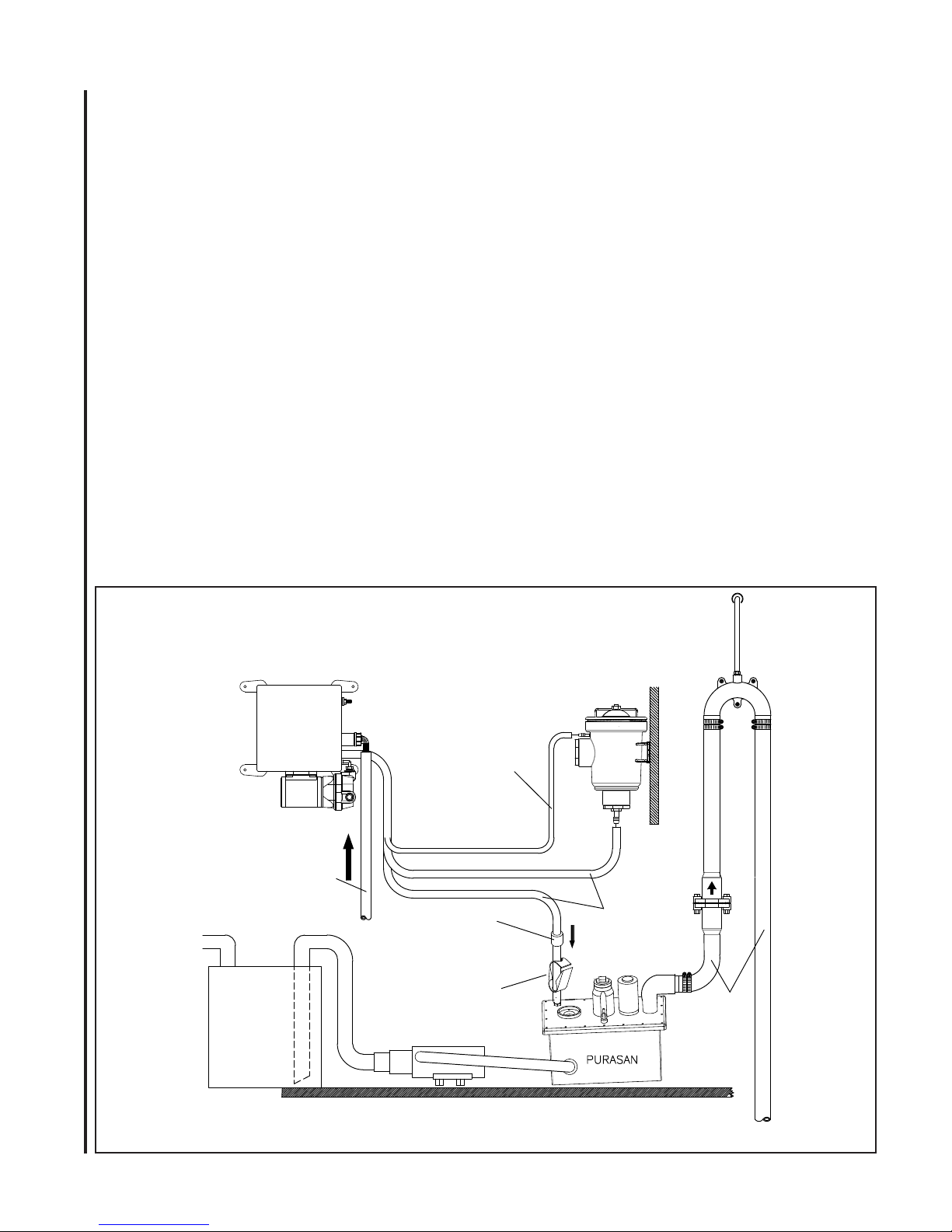
PLUMBING
VENTED LOOP
1 1/2"
HOSE
HOLDING
TANK
MACERATOR
PUMP
FROM
TOILET
TUBING
CLAMP
CHECK
VALVE
3/8"
TUBING
PRESSURIZED
FRESH WATER SOURCE
WITH SHUT OFF VALVE
TABLET
DISPENSER
1/4"
TUBING
WARNINGS:
• All installations made below the waterline MUST be
protected by installing vented loops. Top of the vented
loop must be 4”(10 cm) above waterline at boat’s greatest
angle of heel.
• Always double clamp ttings below waterline
• Use only non-corrosive ttings
A. Macerator pump:
1. Install macerator pump between holding tank and
treatment system.
B. Pressurized water for Tablet Dispenser:
1. Connect hoses from control module to treat-
ment tank and tablet dispenser as per FIG 8
2. A shutoff valve between source and Water
Valve assembly is recommended.
INSTALLATION
3. Use hose clamps to secure hoses
C. Treatment Unit:
NOTE: Use PTFE tape or nonpermanent thread
sealing compound on threaded PVC ttings and
connections. Avoid low areas in hose that would
allow untreated waste to collect.
1. Connect discharge of macerator to one intake
port.
2. Insert plug or second toilet discharge into
other intake port.
3. Determine position and glue discharge elbow
to top of tank using PVC cement.
Note: Be certain that the discharge
elbow is in the correct position before gluing.
4. Connect discharge hose from elbow to thru
hull tting.
Fittings for winterization:
It is recommended that T- tting with a shut of
valve or plug should be installed near intake
port of the treatment unit or lowest part of
the plumbing for draining or ushing system
FIG 8
Plumbing: Pressurized fresh water to Dispenser
8
L519 _0815jlc
Page 9
during winterization
.
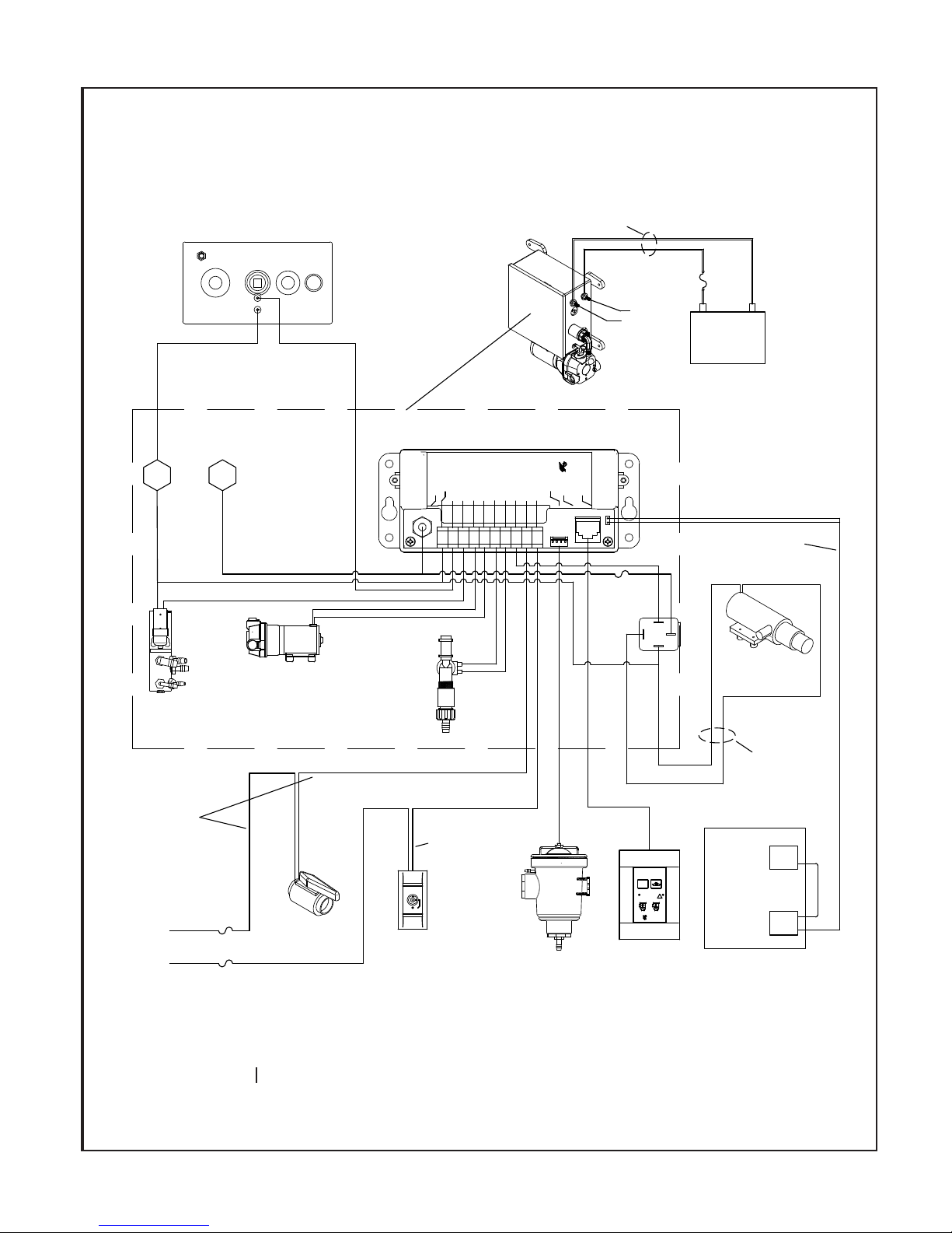
WIRING (See Fig 10)
WARNING: Hazard of Shock and Fire
• Always use proper wire, connectors and fuse/
circuit breaker. See Specication Chart.
• Secure wire properly.
• Do not connect other appliances to
PURASAN® EX circuit.
• Make sure power is off before proceeding.
• Improper wiring can damage the circuit board
and void warranty.
• Motors used with this product are “Ignition
Protected”. They are not however, explosionproof as dened in 46CFR 110.15-65(e),
Subchapter J-Electrical Engineering.
Control Module:
Note: Air pump motor and solenoid coils used
in 12V models are marked 24V.
1. Determine proper wire size from wire chart on
specications page.
2. Fuse or circuit breaker must be installed between
source and control module on positive wire.
3. Run supply wire from source POS to Positive
(POS) terminal on control module, Install rubber
boot on terminal.
4. Run supply wire from source NEG to Negative
(NEG) terminals on module.
5. Run and connect two wires supplied between
macerator pump and control module.
Treatment Unit
1. Run and connect two wire supplied from control
module to treatment tank terminal studs.
WIRING
switch panel or Sensors.
Optional position sensing shutoff valve:
1. Run wires between valve and control module
SPC as per wiring diagram
Optional key switch panel:
1. Run wire between key switch panel and
control module SPC as per wiring diagram
Dual installation:
Dual installation kit PSTEXHNTDC includes
instruction for wiring second switch panel
SensaLevel™ sensor installation:
(sensors are preinstalled at factory for
21Sxxx systems)
Note: Complete all wiring and programming
before installing sensors
1. Turn off power to Control module.
2. Connect wires to the control module
as per wiring diagram FIG 10.
3. Turn on power and place nger in the middle of
low sensor pad. The treatment cycle will start
immediately.
4. Place ngers on both sensor, both LED should
start blinking. If LED’s do not start blinking,
check wiring or contact Raritan technical support.
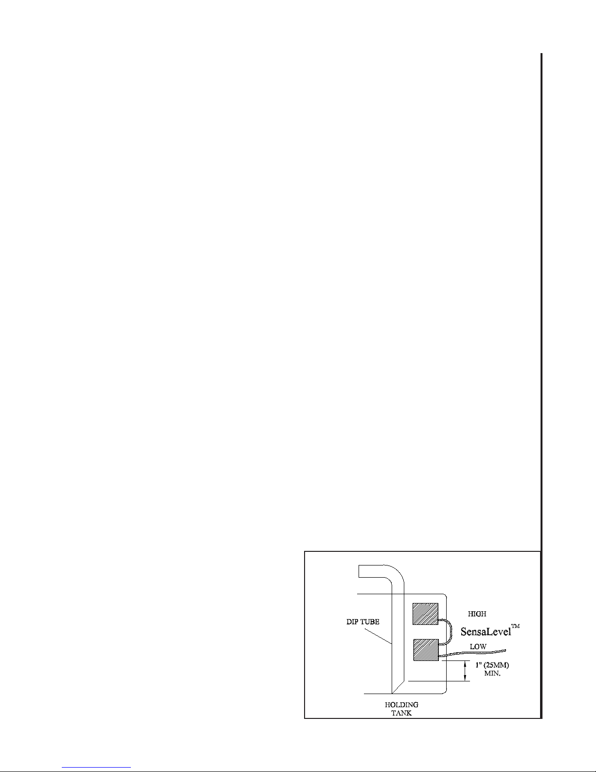
5. Identify a position outside the tank that
will indicate LOW and HIGH level. Low
level is the level where treatment starts.
(FIG 9)
6. Lightly sand the locations where sensors are
to be located to remove oil and dirt.
7. Remove adhesive cover and apply to tank.
Press rmly to remove any air bubbles.
FIG 9
Switch Panel
1. Connect cable from switch panel to SPC
Tablet Dispenser:
1. Run oat cable from Tablet Dispenser to Control
module. Using cable clamp - secure cable on the
wall near dispenser.
2. Connect sensor cable to control module SPC.
Note: Complete programming for Fill and Empty
timing before connecting shutoff valve , key
L519 _0815jlc
9
Page 10
WIRING
Fig 10
PURASAN
TREATMENT
TANK
Purasan Treatment Unit
BLACK 12AWG
RED 12AWG
CONTROL
MODULE
SEE MANUAL
FOR WIRE SIZE
RED
CIRCUIT
BREAKER/FUSE
SEE
MANUAL
POS
NEG
BLACK
+
BATTERY
-
NEG POS
DRAIN
MAINIFOLD
CABLE
18AWG
2 CONDUCTOR
OR MINIMUM
16AWG
INDIVIDUAL WIRES
TO POS
TERMINAL
AIR PUMP
CONTROL MODULE
RED
3 AMP FUSE
BLUE
SEA COCK
(OPTIONAL)
WATER
SOLENOID
RED
KEY SWITCH
(OPTIONAL)
RARITAN
TREATMENT
NO DISCHARGE
NEG
1
M
DVALVE+
BATT +
4
32
BLACK
CABLE
18AWG
2 CONDUCTOR
PURASAN EX
SPC
VALVE+
VALVE-
H1
AIR PUMP-
AIR PUMP+
765
T1
108 9
CABLE
RARITAN
WALL
SWITCH
DISPENSER
PANEL
T2
DISPENSER
HOLDING
TANK
CABLE
FUSE
25 AMP 12V
15 AMP 24V
87
SWITCH
85
86
BLACK 10AWG
RED 10AWG
PURASAN EX
Hold n' Treat
START
STOP
PROCESSING
NO DISCHARGE
!
EMPTY
FILL
RARITAN
PANEL
SensaLevel
BLACK/WHITE OR RED
BLACK
BLACK RED
30
TM
CABLE
18AWG
2 CONDUCTOR
MACERATOR
PUMP
SEE MANUAL
FOR WIRE SIZE
IF LENGTH OF
WIRE NEEDS TO
BE INCREASED
SensaLevel
HOLDING
TANK
TM
L519 _0815jlc
10
Page 11
INITIAL SETTING OF
“FILL” and “EMPTY”
Must be completed during installation to be sure water
reaches level mark on dispenser.
1. All settings should be done with water source (on
board pressure pump or shore water supply) that
will be used with PURASAN. Settings done will
only be valid for that source, and may need to be
reprogrammed if another source is utilized. Lid
must be closed tight during setting and use.
2. Dispenser must not contain tablets during initial
set-up. Program “ll” time without tablet to
reach 1/4” below top marked lines, Unplug sensor cable at Control Module.
3. With power on, press “ll “and count seconds
until water reaches to water level mark on
dispenser. Record seconds as ll. If recorded
seconds are greater than 18 , Open the hole to
approx 1/8” in metering washer between water
valve (221352) and check valve (PX50W) and
repeat.
4. Empty water below tablet dispenser bottom
and entire 3/8” tube till treatment tank while
pressing “empty” button and counting seconds.
Record seconds as empty
5. SET PRELIMINARY “FILL” time:
• Hold the EMPTY & FILL buttons down together
for three seconds. The error LED will give three
quick ashes indicating you have entered program mode - release both buttons.
• Press “FILL “ button as many times as ll
seconds recorded in step 2. example: 8 seconds
press 8 times. Note: maximum is 20 and minimum is 2.
• Push the “START/STOP” button to store this
value (the unit will ash three times indicating
the time has been set and you have left program
mode).
6. SET PRELIMINARY “EMPTY” time:
• Hold the EMPTY & FILL buttons down together
for three seconds. The error LED will give three
quick ashes indicating you have entered program mode - release both buttons.
• Press “EMPTY “ button as many times as empty
seconds recorded in step 3. Note: maximum is 20
and minimum is 2.
• Push the “START/STOP” button to store this
value (the unit will ash three times indicating
the time has been set and you have left program
mode).
7. TEST SETTINGS:
Without tablets: Press start/stop button. Water should
ll up in the dispenser at least up to lower line but no
higher than half way between line. Hold time of water
is 20 seconds and not programmable.
After hold time air pump and drain valve will drain
solution. Make sure that water is drained from entire
tube up to treatment tank. Increase empty time using
step 6 if drain time is not sufcient. After drain cycle,
air pump and water solenoid will stay on for 10 more
seconds (non-programmable) to ush check valve
near tank. Repeat ush cycle to check ll time. If
water is not lling up to level between lines, increase
or decrease ll time using steps 2 to 6.
Note: Cycle after drain cycle can be stopped by pressing start/stop button at any time.
With tablets: Follow start up procedure. Load tablets
and plug sensor cable. If wired to start with toilet:
ush toilet, else press “START/STOP” button, water
should ll up between level line. Make nal adjustment as per above instructions if needed.
Setting of Transfer/macerator pump on time:
Note: Pump time is set to 10 seconds as shipped.
• Hold the EMPTY & FILL buttons down together
for three seconds. The error LED will give three
quick ashes indicating you have entered program
mode - release both buttons.
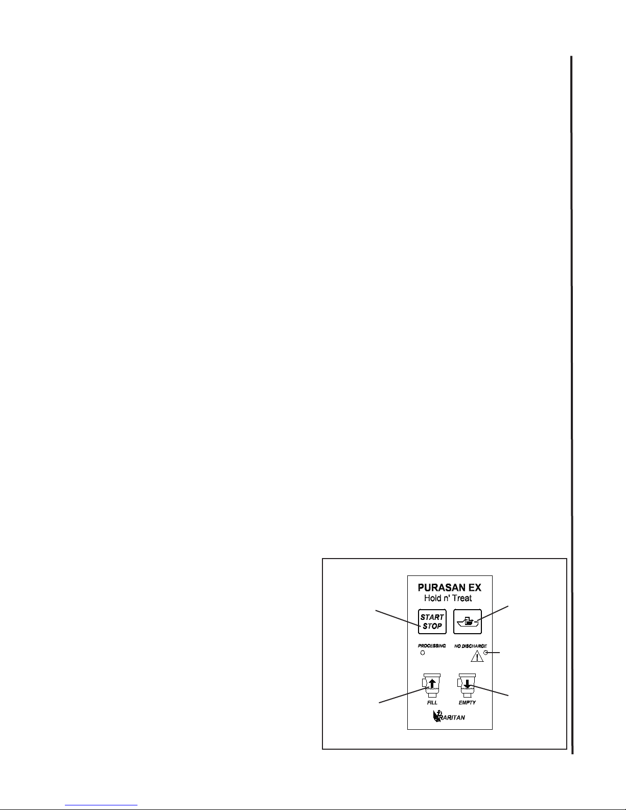
• Press no discharge button (FIG 11) (next to start
/stop button) as many times as needed set pump
on time.(One push = 1 sec’s, two = 2 sec’s,
three= 3 sec’s etc.) The LED will ash once indicating a valid key push. Note: Maximum is 20
seconds.
• Push the “START/STOP” button to store this
value (the unit will ash three times indicating
the time has been set and you have left program
mode).
FIG 11
Treatment
Macerator
PUMP
ERROR
FILL
EMPTY
PROGRAMMING
L519 _0815jlc
11
Page 12
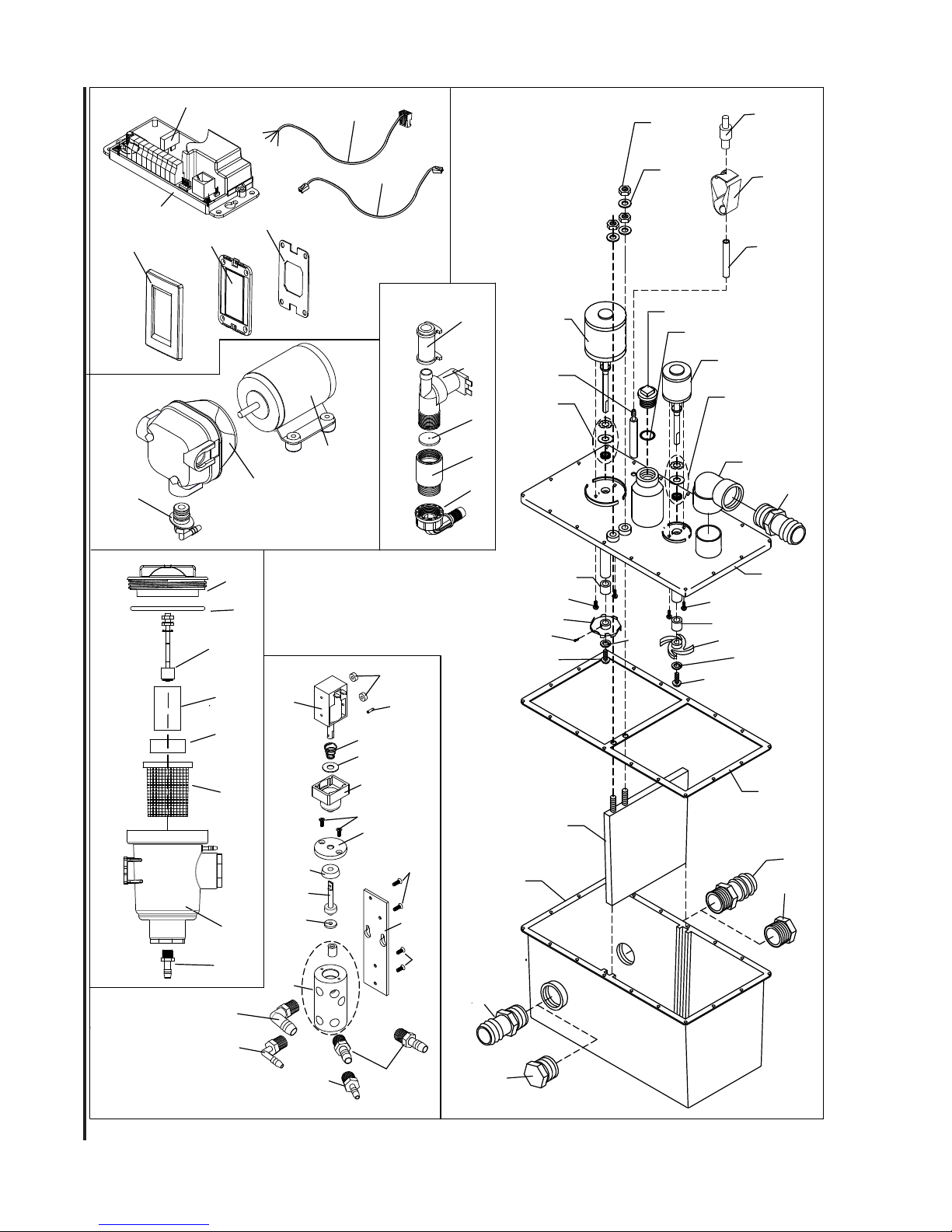
FIG 12
86
SPC**
85
52
58
80
82
72
81
EXPLODED PARTS
83
71
162000WA
48
47
46
45
27
70
84
55
221351W (12V) - 221352W (24V)
39
68
67
69
66
65
17
56
62
10
22
18
51
25
26
1
62
7
8
11
8
7
10
59
57
3
2
19
9
11
41-100AW
41-137W
41
24
29
44
43
40
28
33
34
35
31
37
38
50
36
32
30
53
54
36
2
12
14
13
16
15
2
14
L519 _0815jlc
Page 13

PURASAN PARTS LIST
EXPLODED PARTS
Item Part # Description
1 32-102AW Mixer Motor 2 1/2” Dia. 12 V DC
1 33-102AW Mixer Motor 2 1/2” Dia. 24 VDC
(1) includes shaft seals and bushing for mixer motor)
2 31-121 Hose Fitting (2)
(Not shown) 90
3 31-120 Discharge Elbow 90
6 31-134 Cover Hold down Bolt, 10-32 x 1” (16)
7 31-103 Motor Shaft Bushing (2) (see 62)
8 31-106 Motor Hold down Bolt, 10-32x1”, S/S (4)
9 31-109 Mixer Impeller
10 31-110-1 Impeller Bolt, 12-24 x 5/8”, S/S (2)
11 31-110-2 Impeller Lock Washer, #12, S/S (2)
12 31-114 Cover Hold down Nut, 10-32 (18)
13 31-115PS Treatment Tank
14 31-122 Intake Plug
15 41-102 Tank Divider
16 31-112 Cover Gasket
17 31-108 Macerator Set Screw
18 31-107 Macerator Impeller
19 41-101W Treatment Cover (includes 62,56, 25,26)
22 33-101AW* Macerator Motor for 12 V DC unit
22 34-101AW* Macerator Motor for 24 V DC
(22) includes shaft seal and bushing for Macerator motor
25 31-104CW Crossover Plug with O-ring
26 31-105 O-Ring
51 M31 #14 Brass Flat Washer (4)
52 M30 1/4”-20 Brass Nut (4)
56 31-325A Adapter Tank Lid
57 221335 Hose
58 41-170 Tank check valve
59 31-304C Hose clamp
62 ESTRK EST/PST Repair Kit includes following
(Not Shown) 31-102 Motor Shaft Seal(2)
31-102-1 Macerator Seal Washer
31-102-2 Macerator Retaining Ring
31-102-3 Mixer Seal Washer
31-102-4 Mixer Retaining Ring
31-103 Motor Shaft Bushing(2)
31-105 O-Ring
31-106 10-32x 7/8” Screws (4)
31-112 Cover Gasket
DRAIN MANIFOLD ASSEMBLY(41-137W)
24 41-151A Adapter 1/4” x 1/2” elbow with check valve
27 41-145 Pull Solenoid
28 41-137 Drain Manifold assy.(with check valve)
29 41-151B Adapter 1/8” x 1/4” elbow with check valve
30 41-141
31 PLA3
32 41-139 Cap, manifold
33 41-138C 1/4” x 3/4” U cup seal
34 41-138 B Plunger
35 41-138A Washer for plunger
36 F204 6-32 x 3/8”” Flat head mach. screw(4)
37 LWS Spring
L519 _0815jlc
)0
hose tting (PLA401)
(not shown)
1
/4” NPT x 1/2” barbed adapter
1
/4” Barbed x 1/4” NPT Adapter
o
38 F203 Washer 5/16” x 3/4”
39 F233 Spring Roll Pin
50 41-187 Shaft Boot
53 41-152 Base Plate
54 F232 6-32 x 7/16” Flat head mach. screw (2)
55 F231 Spacer 6” x 5/32”
TABLET DISPENSER (41-100AW)
40 41-130A Dispenser Body.
41 41-177 Adapter 1/2”NPT x 1/2” barb
43 41-156W Tablet holder assembly.
44 41-135A Purasan Tablets (sold saparately)
45 41-179 Float extension pipe
46 41-178W Float sensor
47 RWS5A “O” Ring
48 41-131M Dispenser Cap (machined)
85 41-505 Cable for Float sensor
WATER Valve (221351W, 12V - 221352W, 24V)
65 221356W Inlet hose adapter
66 PX50W Double Check Valve assembly
67 221351 Water Solenoid 12V
67 221352 Water Solenoid 24V
68 221335 1/2” Hose
69 41-157 Metering washer
AIR PUMP for tablet dispenser (162000WA)
70 166024A ** Motor
71 162000W Intake Pump Assembly,air pump
72 162415A Plug with barbed tting
DIAPUMPRK Diaphragm Pump Repair Kit
CONTROLS
80 SPCCHNT Purasan Control
81 41-502 Wall Panel circuit board
82 221514 ME: wall panel cover,white
83 221525 ME; wall panel gasket
84 31-618 Cable for SPC wall panel
86 FUSE10 ATO fuse 10A
OTHER (Not shown)
41-135A Purasan Tablets (Rell)
42-1000A Treatment Unit Complete 12V
43-1000A Treatment Unit Complete 24V
*NOTE: 12VDC units are equipped with a 24VDC
Macerator Motor, 24VDC units are equipped with a
32VDC Macerator Motor.
**NOTE: All models use a 24VDC Motor
13
Page 14
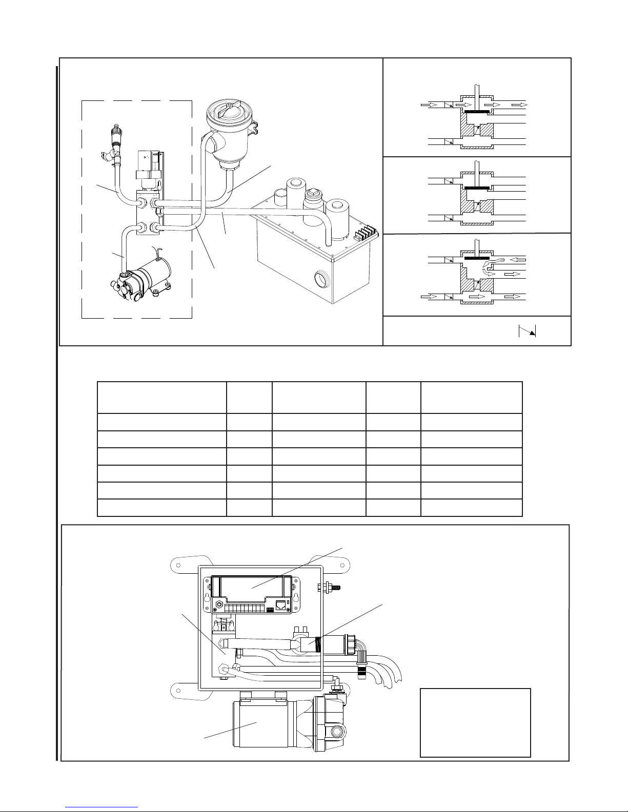
Fig13
Water
Water
Drian
Manifold
Valve
Tablet
Dispenser
Fill/Empty
DRAIN MANIFOLD PORTS
Water in Fill
FILL
CYCLE
HOLD
CYCLE
Air In
To Tank
Air To
EMPTY
CYCLE
Air Pump
Treatment
Unit
Air in
CHECK VALVE SYMBOL
TIME SEQUENCE
Note: Fill time and Empty times are programmable, Total treatment time is 120 seconds
Cycle sequence Motor
TROUBLESHOOTING
Start ON OFF ON ON (1 second)
Drain Solenoid
Air pump
Wate r
Solenoid
Fill cycle ON OFF ON OFF
Hold cycle (20 seconds) ON OFF OFF OFF
Empty cycle ON ON OFF OFF
Wash Cycle (10 sec) ON ON ON OFF
Treatment cycle ON OFF OFF OFF
Location of Components
PURASANEX
CONTROL
SPCCHNT
Empty
To tank
Air to disp
H1
DRAIN
MANIFOLD
41-137W
AIR PUMP
162000WA
14
WATER VALVE
221351W (12V)
221352W (24V)
Note: Check valves
are installed inside
the ttings (41-151)
of drain manifold
L519 _0815jlc
Page 15
TROUBLESHOOTING
WARNING: After the Tablet Dispenser has had water added, it contains a very strong halogen solution. Always wear protective gloves and ventilate well to work on tablet dispenser. Before doing any
maintenance or repairs, follow WINTERIZING/STORAGE procedures .
CAUTION: Tablet Dispenser may be under pressure. Open lid slowly to relieve pressure.
See exploded part view for location of parts
No water to tablet dispenser
• Control malfunction
Check voltage from control to water solenoid
valve. Press ll button and check voltage on the
terminal for water solenoid
• Clogged line, check valve or tting
Check for clog between Water valve and Tablet
Dispenser. Clean or replace clogged part. Check
valve is located inside the tting 41-151A (#24).
• Empty time not programmed correctly
If Drain Manifold and Air Pump is energized too
short to ll the Tablet Dispenser, re programming
is needed. See page 11.
Nothing happens when button is pushed
• Fuses blown
Check fuse on circuit board
• Water level is too high
If water level is high , start and ll button a are
disabled. Empty button will continue to function.
• Cable connection:
Check if cable for switch panel is corroded or
loose.
Error LED
Error LED START BUTTON CAUSE
On Does not work Motor fuse blown
Slow ashing
Fast ashing Does not work Dispenser overlled
Works Tablets need rell
TROUBLESHOOTING
Overow or water level too high in dispenser
• Clogged discharge tting in tablet dispenser
Press empty button to run air pump and clear any
clog.
• Clogged Check valve (treatment tank adapter)
Clean or replace check valve (41-170) located
on the tank
• Water ll time not programmed correctly
If Water Valve is energized too long it will overll
the dispenser, re programming is needed. See
page 11.
• Air pump malfunction:
Press empty button and check voltage on the air
pump terminals. Check the pressure of air pump
(should be at least 5 PSI). Check valve for air
pump is located inside the tting 41-151B(#29).
• Float sensor malfunction:
If error LED indicates water level high and actual
water level is not high , check oat sensor for
proper operation.
L519 _0815jlc
15
Page 16

NOTE:
Discharge of raw, untreated sewage is prohibited in all U.S. waters inside the three mile limit except in the Gulf of Mexico
where the limit is nine miles. “Y” valves, if installed, must direct toilet discharge to a U.S.C.G. approved treatment
system or holding tank and must be secured in that position while inside the three-mile limit.
The EPA standards state that in freshwater lakes, freshwater reservoirs or other freshwater impoundments whose inlets or
outlets are such to prevent the ingress or egress by vessel trafc subject to this regulation, or in rivers not capable of navigation
by interstate vessel trafc subject to this regulation, marine sanitation devices certied by the U.S. Coast Guard installed on all
vessels shall be designed and operated to prevent the overboard discharge of sewage, treated or untreated, or any waste derived
from sewage. The EPA standards further state that this shall not be construed to prohibit the carriage of Coast Guard-certied
ow-through treatment devices which have been secured so as to prevent such discharges. They also state that waters where
a Coast Guard-certied marine sanitation device permitting discharge is allowed including coastal water estuaries, the Great
Lakes and interconnected waterways, freshwater lakes and impoundments accessible through locks, and other owing waters
that are navigable interstate by vessels subject to this regulation (40 CFR 140.3)
LIMITED WARRANTY
Raritan Engineering Company warrants to the original purchaser that this product is free of defects in materials or workmanship for a period of one year
from the product’s date of purchase. Should this product prove defective by reason of improper workmanship and/or materials within the warranty period
, Raritan shall, at its sole option, repair or replace the product.
1. TO OBTAIN WARRANTY SERVICE, Consumer must deliver the product prepaid, together with a detailed description of the problem, to Raritan at
530 Orange St., Millville, N.J. 08332, or 3101 SW 2nd Ave. Ft. Lauderdale, FL 33315. When requesting warranty service, purchaser must present a
sales slip or other document which establishes proof of purchase. THE RETURN OF THE OWNER REGISTRATION CARD IS NOT A CONDITION
PRECEDENT OF WARRANTY COVERAGE. However, please complete and return the owner Registration Card so that Raritan can contact you should
a question of safety arise which could affect you.
2. THIS WARRANTY DOES NOT COVER defects caused by modications, alterations, repairs or service of this product by anyone other than Raritan;
defects in materials or workmanship supplied by others in the process of installation of this product; defects caused by installation of this product other
than in accordance with the manufacturer’s recommended installation instructions or standard industry procedures; physical abuse to, or misuse of, this
product. This warranty also does not cover damages to equipment caused by re, ood, external water, excessive corrosion or Act of God.
3. ANY EXPRESS WARRANTY NOT PROVIDED HEREIN, AND ANY REMEDY FOR BREACH OF CONTRACT WHICH BUT FOR THIS PROVISION MIGHT ARISE BY IMPLICATION OR OPERATION OF LAW, IS HEREBY EXCLUDED AND DISCLAIMED. ALL IMPLIED WARRANTIES
SUCH AS THOSE OF MERCHANTABILITY AND OF FITNESS FOR A PARTICULAR PURPOSE, IF APPLICABLE, AS WELL AS ANY IMPLIED
WARRANTIES WHICH MIGHT ARISE BY IMPLICATION OF LAW, ARE EXPRESSLY LIMITED TO A TERM OF ONE YEAR. SOME STATES
DO NOT ALLOW LIMITATIONS ON HOW LONG A LIMITED WARRANTY LASTS, SO THE ABOVE LIMITATION MAY NOT APPLY TO YOU.
4. UNDER NO CIRCUMSTANCES SHALL RARITAN BE LIABLE TO PURCHASER OR ANY OTHER PERSONS FOR ANY SPECIAL OR CONSEQUENTIAL DAMAGES, WHETHER ARISING OUT OF BREACH OF WARRANTY, BREACH OF CONTRACT, OR OTHERWISE. SOME STATES
DO NOT ALLOW THE EXCLUSION OR LIMITATION OF INCIDENTAL OR CONSEQUENTIAL DAMAGES, SO THE ABOVE LIMITATION OR
EXCLUSION MAY NOT APPLY TO YOU.
5. No other person or entity is authorized to make any express warranty, promise or afrmation of fact or to assume any other liability on behalf of Raritan
in connection with its products except as specically set forth in this warranty.
6. This warranty gives you specic legal rights, and you may also have other rights which vary from state to state.
530 Orange Street, Millville, NJ 08332 USA
Telephone: 856-825-4900 FAX: 856-825-4409
Website: www.raritaneng.com
Southern Ofce and Plant:
3101 SW Second Avenue, Fort Lauderdale, FL 33315 USA
Telephone: 954-525-0378 FAX: 954-764-4370
L519 _0815jlc Specications Subject to Change Without Notice Printed in U.S
16
 Loading...