

Page 1

Safety, Operation & Maintenance Manual
Ransomes Spider I Remote Controlled Rotary Mower
Product Code: ILD01W
WARNING
WARNING: If incorrectly used this machine can cause
severe injury. T hose who use and maintain this m achine
should be trained in its proper use, warned of its d angers
and should read the entir e manual bef ore attem pting to set
up, operate, adjust or service the machine.
RJL 100 August 2010
24735-GB (Rev.7)
Page 2

Operation manual - Spider ILD01
2 / 54 rev. 07-01-01-2010
1 CONTENTS
1 CONTENTS ......................................................................................................................................................... 2
2 INTRODUCTION ............................................................................................................................................... 4
2.1 IMPORTANT ................................................................................................................................................. 4
2.2 M ACHINE USAGE ....................................................................................................................................... 5
2.3 PROHIBITED USE ....................................................................................................................................... 5
2.4 PRODUCT IDENTIFICATION ...................................................................................................................... 6
2.5 GUIDELINES FOR THE DISPOSAL OF SCRAP PRODUCTS .................................................................. 7
3 SAFETY INSTRUCTIONS .................................................................................................................................. 8
4 SPECIFICATION ............................................................................................................................................... 11
4.1 SPECIFICATION ........................................................................................................................................ 11
4.2 NOISE EMISSIONS .................................................................................................................................... 11
4.3 CONFORMITY CERTIFICATES ................................................................................................................ 12
5 SAFETY DECALS ............................................................................................................................................. 13
5.1 INSTRUCTION DECALS .............................................................................................................................. 15
5.1 RECOMMENDED METODS OF OPERATION ............................................................................................. 16
6 CONTROLS ...................................................................................................................................................... 18
6.1 REMOTE RADIO CONTROLLER NBB ..................................................................................................... 18
6.2 REMOTE RADIO CONTROLLER HETRONIC .......................................................................................... 19
6.3 MOWER CONTROLS ................................................................................................................................. 20
7 DISPLAYS ......................................................................................................................................................... 21
7.1 NBB RADIO CONTROL DISPLAYS .......................................................................................................... 21
7.2 HETRONIC RADIO CONTROL DISPLAYS............................................................................................... 21
7.3 MOWER DISPLAYS ................................................................................................................................... 21
8 SAFETY SYSTEMS .......................................................................................................................................... 23
8.1 MOWER SAFETY SYSTEMS .................................................................................................................... 23
9. PREPARING THE MACHINE .......................................................................................................................... 24
9.1 MACHINE DELIVERY TO A DEALER OR RETAILER ............................................................................. 24
9.2 GEAR-BOX BY-PASS................................................................................................................................ 25
9.3 CHECKING ENGINE OIL LEVEL .............................................................................................................. 25
9.4 CHECKING HYDRAULIC DRIVE OIL LEVEL ........................................................................................... 26
9.5 PREPARING THE BATTERY .................................................................................................................... 26
9.6 FUEL TANK ................................................................................................................................................ 27
9.7 PREPARING THE NBB REMOTE RADIO CONTROLLER ...................................................................... 27
9.8 CHARGING THE NBB REMOTE RADIO CONTROLLER BATTERY ..................................................... 27
9.9 PREPARING THE HETRONIC REMOTE RADIO CONTROLLER .......................................................... 28
9.10 CHARGING THEHETRONIC REMOTE RADIO CONTROLLER BATTERY ......................................... 28
10 OPERATION ................................................................................................................................................... 28
10.1 TRANSPORTING THE MOWER ............................................................................................................. 28
10.2. STARTING THE ENGINE OF THE MOWER WITH THE NBB REMOTE CONTROL ........................... 29
10.2. STARTING THE ENGINE OF THE MOWER WITH THE HETRONIC REMOTE CONTROL ................ 30
10.3 SHUTTING OFF THE ENGINE ................................................................................................................ 31
10.4 EMERGENCY SHUTTING OFF OF THE ENGINE .................................................................................. 31
10.5 ENGAGING THE MOVING BLADES ....................................................................................................... 32
10.6 DISENGAGING THE BLADES ................................................................................................................ 32
10.7 HEIGHT OF CUT ADJUSTMENT ............................................................................................................ 32
10.8 DRIVING THE MACHINE ......................................................................................................................... 33
10.10 DRIVING ON SLOPES ........................................................................................................................... 34
10.11 STOPPING THE MACHINE ON A SLOPE ............................................................................................ 34
11 MAINTENANCE AND LUBRICATION ........................................................................................................... 35
11.1 MAINTENANCE CAHRT - MOWER ........................................................................................................ 35
11.2 MAINTENANCE CHART - ENGINE ......................................................................................................... 36
11.3 ENGINE MAINTENANCE ........................................................................................................................ 37
11.4 CLEANING THE FUEL TANK ................................................................................................................. 37
11.5 MAINTAINING THE HYDRAULIC DRIVE ............................................................................................... 37
11.6 CHECKING AND REFILLING OIL ........................................................................................................... 38
11.7 ADJUSTMENT OF THE NEUTRAL POSTION OF THE HYDRAULIC DRIVE ....................................... 38
11.8 DRIVE V-BELTS ....................................................................................................................................... 39
11.9 GEOMETRY ADJUSTMENT .................................................................................................................... 39
11.10 FINAL GEAR DRIVE TO WHEELS ....................................................................................................... 40
11.11 MAINTAINING ELECTRIC CIRCUITS AND DEVICES, TRANSMITTER ............................................. 40
11.12 ADJUSTING BLADE DECELERATION ................................................................................................ 40
11.13 CHAINS .................................................................................................................................................. 40
11.14 FUSES .................................................................................................................................................... 41
11.15 MOWING BLADE ................................................................................................................................... 42
Page 3

Operation manual - Spider ILD01
3 / 54 rev. 07-01-01-2010
11.16 CHANGING THE WHEEL ...................................................................................................................... 43
11.17 TYRE PRESSURE.................................................................................................................................. 43
11.18 MOWING HEIGHT ADJUSTMENT MECHANISM ................................................................................. 43
11.19 LUBRICATION ....................................................................................................................................... 44
11.20 CLEANING THE MACHINE ................................................................................................................... 45
11.21 TORQUE CHART ................................................................................................................................... 45
11.22 OIL VISCOSITY ...................................................................................................................................... 45
11.23 TECHNICAL PLATE .............................................................................................................................. 46
11.24 TOOLS .................................................................................................................................................... 46
12 TROUBLESHOOTING .................................................................................................................................... 47
13 MAINTENANCE AFTER SEASON ................................................................................................................. 49
14 WARRANTY CONDITIONS ............................................................................................................................ 50
15 BILL OF DELIVERY........................................................................................................................................ 52
Page 4

Operation manual - Spider ILD01
4 / 54 rev. 07-01-01-2010
2 INTRODUCTION
2.1 IMPORTANT
This is a precision m ac hin e a nd th e s erv ice obtained from it depe nds o n th e way it is operated
and maintained.
This OPERATION MANUAL should be regarded as part of the machine and should always be
present at the machine and available to the operator. Suppliers of both new and second-hand machines
are advised to retain documentary evidence that this manual was provided with the machine.
This machine is designed solely for use in customary grass cutting operations. Use in any other way is considered as
contrary to the int ended use. Com pliance wit h and str ict adher ence to the c ond itio ns of oper at ion, s ervice and r epa ir
as specified by the manufacturer, also constitute essential element of the intended use.
Before attempting t o operate this m achine, ALL operators MUST go through a practical tr aining in m achine usage,
read through this m anual and mak e themselves thorou ghly conversan t with Safet y Instructions, contr ols, lubricat ion
and maintenance. T he machi ne may be oper ated wit h additiona l accessor ies specif ically des igned for th is purpose.
Operating and Safety Instructions of such accessories must be strictly adhered to.
Accident prevention regulations , all other gen eral l y recogn ized r egu lat ions on safe ty an d occ upa tio nal med ic ine, a nd al l
road traffic regulations shall be observed at all times.
Any arbitrary modifications carried out on this machine as well as non-adherence to this
OPERATION MANUAL m ay r elieve th e m anufacturer o f l iability fo r a ny r esulting d amage o r
injury.
2006/42/EC These are the original instructions verified by Dvořák – svahové sekačky, s.r.o.
In several places this Manual contains instructions for safe work. If the text includes such an instruction, then the
instruction is marked by the following WARNING symbol:
Warning against a highly probable danger of severe injury or life threat if appropriate instructions are not
followed.
other symbols:
Provides useful information.
Page 5

Operation manual - Spider ILD01
5 / 54 rev. 07-01-01-2010
2.2 MACHINE USAGE
The machine is designed for the mowing of grass on level as well as extremely steep terrain. The mower may be
used on dry surface under the following conditions:
Maximum slope 24 degrees on well-maintained la wns (gardens, park s tec.) in konform ity with EN
836+A1+A2.
Cutting across a slope – maximum slope 30°.
or
Cutting up & down a slope - maximum slope 35°
Cutting across the slope with mower positioned diagonally – maximum slope 40°.
All in konformity with EN 745
The Spider is a mulching mower for use in the mowing of uncared-for or only occasionally mowed areas. The
mower is operated by one person using radio control.
The mower may only be operated by authorized persons over 18 years of age both mentally and physically fit,
who are famil iar w ith this Safety, O p erator’s and Ma in te n ance Manual and a l l a p pl ic ab l e r e gu l at io ns a n d l a ws
pertaining to work health and safety that need to be observed while operating the mulching mower Spider.
2.3 PROHIBITED USE
The mower must not be used on surfaces littered by glass, loose stones, pieces of iron and other foreign objects that
can either be thrown by the blades du ring mowing or da mage the mower.
The mower must not be used on slopes exceeding 20 degrees when wet or foggy as the climbing ability and mower
stability are adversely influenced by poor ground adhesion.
Do not use the mower to mow uncared-for or only occasionally mowed surfaces where other people, children or
animals can be found within 20 m (65 ft.) from the mower/mow ed area.
Do n ot u se th e m ower unless you a re p roperly a cquainted w ith the te rrain a nd m ainly w ith th e
occurrence of undesired terrain irregularities, stumps, swamps, pits and poor load bearing soil.
The mower must not be used as a towing/transporting device or as means of transporting persons.
It is prohibited to drive the mower on public thoroughfares.
It is prohibited to increase the engine revolutions or the engine performance above the limits specified by the manufacturer.
It is also prohibited to make any other modifications to the machine construction or to the engine setup. The manufacturer
does not bear any liability for damage or injury resulting from such modifications.
Page 6
Operation manual - Spider ILD01
6 / 54 rev. 07-01-01-2010
2.4 PRODUCT IDENTIFICATION
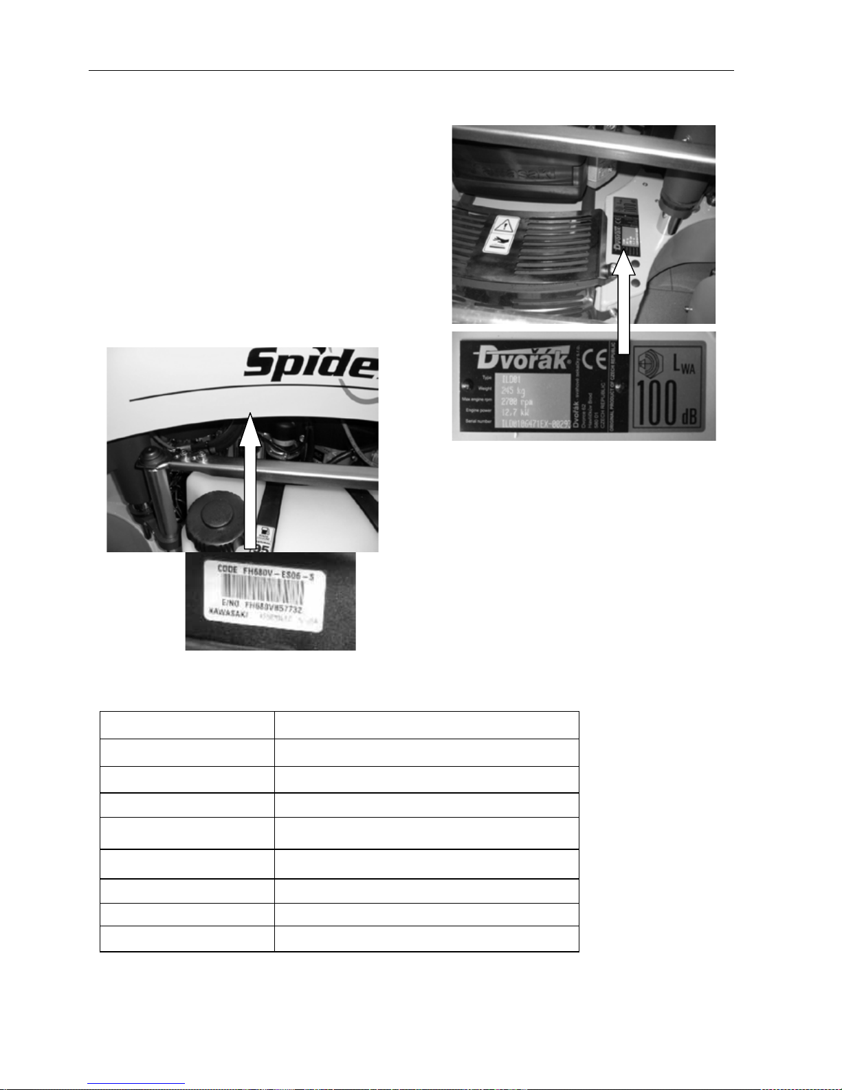
The machine can be identif ied b y the ser ial number, which
can be found on the factory label on the front of the
machine beside the ex haust pipe. The serial num ber and
the year of manufacturing m ust be provided during every
request for servicing and with every order of spare parts.
On the internal engine you can also find a factory label
placed there by the engine manufacturer. We strongly
recommend that you copy this data to the chart below
while taking over the m achine, and cons equentl y use them
during an y further comm unication with the m anufactur er or
the servicing facility.
Mower factory label location
Engine factory label location
Data to be filled in and confirmed by the dealer:
Product serial number
Engine type
Engine serial number
Year of manufacturing
Address of your dealer
Address of servicing facility
Date of delivery
Warranty expiration date
Warranty term interruption
Declaration
I h ave r ead a nd u nderstood th e o perating
and safety instructions in this manual
Signature
_____________________________________
Page 7

Operation manual - Spider ILD01
7 / 54 rev. 07-01-01-2010
2.5 GUIDELINES FOR THE DISPOSAL
OF SCRAP PRODUCTS
When it has be en ident ified that a tur f care pro duct
has no further functional value and requires
disposal, the following actions should be taken.
These guidelines should be used i n conjuncti on with
Health, Safety and Environmental legislation and use
of approved local facilities for waste disposal and
recycling.
• Position the machine in a suitable
location for any necessary lifting
equipment to be used.
• Use appropriate tools and Personal
Protective Equipment (PPE) and take
guidance from the technical manuals
applicable to the machin e.
• Remove and store approp riately :
1. Batteries
2. Fuel Residue
3. Oils
Disassem ble the structur e of the machine r eferring
to the techn ical m anual s wher e appr opria te. Sp ecial
attention should be made for dealing with “stored
energy” within pressurized elements of the machine
or tensioned springs.
Any items that still have a useful service life as
second hand components or can be re-serviced
should be separated and returned to the relevant
centre.
Other worn out items should be se parated into
material groups for recycling and disposal
consistent with available facilities. More
common separation types are as follows:
• Steel
Non ferrous metals
• Aluminium
Brass
• Copper
• Plastics
• Identifiable
• Recyclable
• Non recyclable
• Non identified
• Rubber
• Electrical and electronic components
• Items that cannot be separated
economically into diff erent material groups
should be added to the “General waste”
area.
• Do not incarnate waste.
Finally update machinery records to indicate that the
machine has been taken out of service and scrapped.
Page 8

Operation manual - Spider ILD01
8 / 54 rev. 07-01-01-2010
3 SAFETY INSTRUCTIONS
This safety symbol indicates important
safety messages in this m anual. W hen you
see this symbol, be alert to t he pos sib ilit y of
injury, carefully read the message that
follows, and inform other operators.
Safety Checks
• Do not enter or reach under the machine if it is
lifted and not sufficiently supported. The machine
should be supported on places marked by the
symbol of a lifting jack.
• The mower should only by transported in a
container or on a trailer.
• Check bolt torques at regular intervals. The first
check should be done after 8 operating hours.
Pay attention to th e attachment of the cutting
blade and the proper bolt torque. Use a torque
wrench and a specifi ed torque. See 11.21.
• The attaching flange of the blades or the bolts
must not show sign of damage or wear. The bolts
must be complete. The blade must be
undamaged, evenly worn and adequately sharp.
• If you are driving the machine outside the
working area, always turf off the mowing blade
and set the maximum mowing height, otherwise
the blade may get damaged.
• Keep the product clean after use. Do not use
gasoline or similar oil products for cleaning.
• Do not reach into the space under the mower
with your hands o f feet. Do not reach under the
engine cover or into the gear mechanism.
• If you are forced to reach under the machine, wait
until all rotating parts stop. Attention, it takes
some time before blade runs down! The rundown time depends on the state and wear of the
brake/clutch. Have the brake checked at regular
intervals at an authorised servicing facility.
• While operating, wear closed shoes and work
clothing. Do not wear loose clothes that could get
caught by the machine, short trousers or light
shoes.
• It is strictly prohibited for the operator to wear
loose clothing.
• A local risk assessment should determine the
need for a face shield.
• Do not operate the machine after drinking alcohol
or using medication influencing perception.
• Before starting the engi ne, make sure that the
mower blade is dis engaged. If the blade switch
is in the ON position, the machine cannot be
started. When engaging th e mower blade, step
aside far enough to be protect ed against object
accidentally throw n from the mower and to be
able to stop the mower in case of an
emergency. Do not enter the path of the mower.
• While operating the mower make sure that the
mower is clearly visible at all times and within
the range of the remote control unit and that
you can clearly recognize dangerous situations
and react to them properly. Do not abuse the
maximum reach of the remote control.
• When using the mower, follow all general work
safety regulations.
• Work with the mower may only be started if the
mower is not damaged by previous operation.
• Do not change the engine tuning, especially the
engine speed regulator. Do not modiy the
exhaust pipe.
• Do not use the mower if there is less than 30%
of fuel in the fuel tank.
• Do not move the mo wer b y means of towing it
behind another machines.
Operating Environment
• The machine should only be used by persons
over 18 years of age, who have been
acquainted with the machine and the user’s
manual .The remote control (further referred to
as ”RC”) is considered a part of the machine
• The user’s manual must be stored in a place
permanently accessible to the operator and
must be available to him at all times.
• Do not allow children or unauthorised persons
use the product.
• Before starting to operate the machine, you
have to be familiar with all the symbols next t o
the controls and indicators used on the mower
and the RC.
• Pay special attention to the stopping and
shutting-off of the engine and to the emergency
shutting-off of the mower.
• Before using the mower on a slope, make sure
you test and practice your mower-control skills
on flat and level gro und, which is sufficiently free
and spacious. Master how to control the
movement on a surface, to mow around bushes,
trees and other terrain elements and obstacles.
• When operating the mower on slope, make sure
that the engine revolutions are set to maximum
speed. If you stop the mower on a slope, position
the wheels across the slope.
• While operating or transporting the mower, the
operator must alw ays have the mowe r in their
view. The maximum distance between the
operator and the mower is 50 m (164 ft).
• While using the mower follow all safety
regulations given in this manual and respect
local regulations and provisions concerning
noise-emissions, especially when using in
hospitals, spas and other sensitive areas.
• The operator mus t pa y at tent ion to t he are a int o
which the mulched grass may be blown. Neither
the operator, n ot any other perso ns, children or
animals shoul d be allowed to enter th is area. If
mowing uneven te rrain th e ejecti on and th row ing
Page 9

Operation manual - Spider ILD01
9 / 54 rev. 07-01-01-2010
of undesirable objects becomes more probable
due to the displacement of the mowing device (tilt
of one side of the m achine) while crossing the
edges of different terrain.
• The operator of the machine may be responsible
for any damage caused to third parties by
operating the machine. The mower may be used
on dry surface on slopes listed in chapter 2.2. On
wet or moist surfaces the mowed slope should
not exceed 20 degrees.
• Before operating the machine, make sure you
remove from the mowing area all loose stones,
sticks, glass, wire, bones, branches and all other
objects that can be picked up by the blades and
thrown or that could damage the mower.
• While operating the mower avoid obstacles, do
not drive over higher obstacles (such as stones,
stumps, brick), near precipices, on unstable soil
or in places where the mower could fall down or
flip over.
• When operating pay attention to electric power
lines especially when d riving be neath electri c
wires where the radi o signal may be l ost. In such
case the mower immediately shuts off the internal
combustion engine and stops all movements.
• When using the machine near busy
thoroughfares make sure that the mower does
not endanger (by throwing undesirable objects)
passers-by or their property. Choose a suitable
working procedure (see chapter: Operating the
mower).
• The operator/user is responsible for the
safety of persons that enter the working area
of the machine. Stop your work if these
persons enter the working area.
• The transportation of persons, animals or loads
on the mower is prohibited.
• Do not place any objects or tools on the product.
• While operating, especially in windy conditions,
choose the operator’s position carefully so as to
keep the operator away from the stream of
exhaust gas, dust or mulched grass.
• Stop work and clean the machine and its cooling
surfaces several times while working in dusty
conditions to avoid over-heating during operation.
If necessary, clean the machine and its cooling
surfaces several times while working. The dust
layer must not exceed 1m (3 ft).
• Refuel only when the machine is off – before
operating, if possible – and the fuel tank is
cold. Always keep at least 30% of the fuel in
the tank. If you need to refuel during your work,
do not fill the fuel into a hot tank or while the
engine is still hot. Let the machine cool down.
• Before refuelling push the STOP button on the
control panel of the mower.
• Never refuel while the engine is running.
• Do not start the engine if you find spilled fuel,
open vessels with fuel or other combustible
objects or gases in the immediate proximity of
the mower.
• Do not refuel near open fire.
• Do not place this product near open fire or other
sources of heat.
• While operating or immediately after shutting
the machine off do not touch those parts of the
machine that heat up during operation. This
concerns mainly the engine exhaust pipe, metal
parts of the hydraulic drive and metal parts of
the internal combustion engine.
• While operating do not touch the highvoltage
conductor leading to the sparking plug.
• After starting the engine, test the correct
functioning of the emergency engine stop on
the radio transmitter. This function should be
checked at least once during every shift and
every time you enter a new area for mowing or
mulching.
• Before starting your work test the correct
functioning of the safety components
(EMERGENCY STOP...) on the mower and the
RC.
• Never leave the engine running without
supervision.
• If the engine is running, do not put aside the
transmitter and do not touch or move any parts
of the machine.
• Always stop the engine when leaving the
machine, secure it against starting by pushing
the red EMERGENCY STOP button on the
control panel of mower and by removing the
key. Never leave the transmitter next to the
mower, but put it in a different, properly secured
place inaccessible to third persons.
• Do not engage the mowing blade until
immediately before mowing.
• Turn off the mowing mechanism , shut off the
engine and rem ove the from the ignition every
time:
• You clean the machine
• You remove dirt from the mowing mechanism
(grass or debris).
• You run over an unknown object and need to
check for possible damage or to repair it
• The machine unusually intensively vibrates and
you need to find the cau se
• You repair the engine or other parts of the
mower (also unplug cables from sparking plugs)
• While operating, avoid mole-hills, concrete
bases, guard-stones, st umps, loose sto nes and
curbs. These m ust not come in to direct contac t
with the blade as they could cause serious
damage. These may also compromise the
mower stability.
• Do not drive the mower into heaps of sand,
gravel or similar materials
• The mower may only be operated during
daylight or under very good artificial light
Page 10

Operation manual - Spider ILD01
10 / 54 rev. 07-01-01-2010
conditions.
• Do not use the mower in limited visibility (dusk,
fog, heavy rain et c.)
• Do not let the engine run in enclosed spaces.
The exhaust gases contain CO, they damage
health and can ultimately cause death.
• The engine should only be started and operating
in open spaces. I f the engine is sta rted and
operated in enclosed spaces, the exhaust gases
must be conducted away by the means of
prolonging the exhaust pipe outside the enclosed
space. Proper ventilation and fresh air supply
must be secured in order to prevent the
accumulation of CO.
• Before storing the machine in a closed space, let
the engine and the hydraulic drive of the machine
cool properly.
• Regularly remove all combustible objects (dry
grass, leaves...) from the areas around the
exhaust pipe, engine, and battery.
• Always control the machine from a working
station, which gives you a perfect view of the
whole working area and of the machine.
• While working, change your working position to
have a perfect view of the mower at all times.
• When operating the mower on slopes never enter
the space directly below the mower.
• The working position should be far enough
(maximum 50 meters) to prevent the operator
from getting hit by objects that may be
accidentally thrown by the mower.
• Do not operate the mower if you cannot see it
(behind terrain obstacles, corners of buildings,
hidden in grass etc.)
Safety Decals
• Before starting the mower, check the state of the
safety labels. If any labels are damaged or
missing, contact your dealer and replace such
labels on the machi ne. Get thoroug hly
acquainted with these labels. The placement of
the labels on the machine is obligatory.
• Do not remove or damage any of the safety
labels.
• Do not remove any covers or safety elements.
They are for your protection.
• Do not use the machine if any of the protecting
devices or covers are damaged or missing.
• Keep the machine and its accessories clean and
in a good technical condition at all times.
• It is strictly prohibited to make any changes or
modifications to the machine that were not
previously approved by the manufacturer. Any
modification to the machine may lead to a
hazardous situation or injury. If these instructions
are not followed, the manufacturer does not bear
any liability for the machine and the terms of
warranty may be invalidated..
• The machine must always be e quipped wit h all
covers and protective elements.
Page 11

Operation manual - Spider ILD01
11 / 54 rev. 07-01-01-2010
4 SPECIFICATION
4.1 SPECIFICATION
TECHNICAL DESCRIPTION
The mower is a self-propelled machine with four-wheel drive, controlled by the transmitter (remote radio
controller) signal. Its unique wheel-steering technology ensures a high manoeuvrability both on level ground and
on slopes.
The basic part of the machine is formed by a square solid frame, which is connected with a sliding frame. The
middle part of the sliding frame carries all transmission parts such as the engine, the hydraulic pump, the oil
cooler and the control unit. A cutter blade is attached to the bottom part of the frame. An electromagnetic clutch
is placed between the blade carrier and the engine.
Transmission is by chains and gears on all four wheels. The wheels are driven centrally by the hydraulic drive
through V-belts. The wheels are steered by an electric motor.
The control unit is situated in a box above the cover of the gel battery. The mower is controlled by a multichannel transmitter.
Parametr
Unit
Value
Length/Width
mm (inch)
1300x1300 (51,2x51,2)
Height
mm (inch)
850 (33,47)
Mowing width
mm (inch)
800 (31,52)
Mowing blade height
mm (inch)
60 - 110 (2,36 – 4,33); 30 - 80 (1,18 - 3,14)
continuous regulation
Weight
Kg (pound)
245 (540)
Driving speed
km/h (mph)
0 – 3, 0 – 7 (0-2, 0-4,5)
Mowing mechanism - Single-balde with a fixed balde attac h ed b y the
flange int the middle
Mowing clutch
-
Electromagnetic with a friction brake
Hydraulic pump Hydro Gear BDP 21L
Hydraulic motor - Sauer Danfoss OMP 40
Propelled wheels
-
4 x 4
Travel wheel
inch
4,00 x 8 with an arrow (V) tread pattern, 4,00 x 16
with and arrow (V) tread pattern
Battery
12 V, 18 Ah, gel
Fuel
-
benzín - natural
Fuel tank capacity
L (galon)
10 (2,6)
Engine Air-cooled four-stroke two cylinder
Kawasaki FH500V FH531V Kohler CV18S
Cylinder volume
cm3
494
494
624
Performance
HP/min-1
17/3600
18/3600
18/3600
Torque
N . m/min-1
37/2400
39/2400
41/2500
Ignition
Electronic
Starter
Electric
Frequency range of the
Remote
controller NBB for
EU and USA
MHz 433.100 - 434.750
4.2 NOISE EMISSIONS
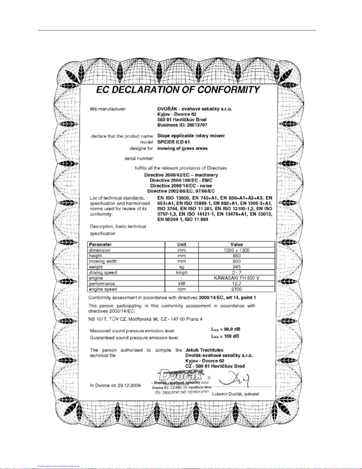
The mower emits the following noise: Sound pressure level LWA = 98,9 dB
Guaranteed Sound pressure level LWA = 100 dB
The measuring was carried out in conformity with ČSN EN ISO 3744
Noise at the operator’s station (ear): L = 85 dB (A) Leq – Measur ed in the distanc e of 1m from the m achine
according to EN 11201
Page 12
Operation manual - Spider ILD01
12 / 54 rev. 07-01-01-2010
4.3 CONFORMITY CERTIFICATES
Page 13
Operation manual - Spider ILD01
13 / 54 rev. 07-01-01-2010
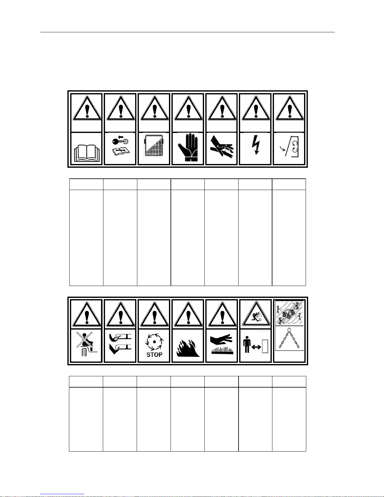
5 SAFETY DECALS
Attention! T his machine m ay b e d angerous. I ncorrect an d n egligent use m ay r esult in damage, s erious
injuries or death. T his c hapter is devoted to t he s afety symbols (p ictograms) u sed o n t he p roduct, th eir
placement a nd m eaning. S afety l abels i nform th e o perator a bout r isks w hile u sing t he p roduct.
Understanding their meaning will make the use of this product safe.
1 2 3 4 5 6 7
Read the user’s
manual before
use
While
maintaining,
repairing or
adjusting t he
mower, follow
the user’s
manual and
remove the key
from the igni tion
Use protective
work aids; face
shield
Attention, us e
protective gloves
when changing
the mowing
blades
Attention, the
device uses
hydraulic energy
drive, danger of
injury caused by
the squirting
hydraulic oil
Attention,
electric
accumulator
Before starting
close all
protective covers
8 9 10 11 12 13 14
Transporta tion of
persons on the
machine is
prohibited
Attention, d anger
of hand or feet
injury caused by
rotating blades
Attention,
rotating parts are
decelerating after
they were turned
off
Attention,
combustible
substance,
danger of fire
Danger of getting
burned by hot
parts
Attention, d anger
of getting hit by
flying object.
Keep safe
distance.
On slope never
enter the area
below or directly
above the
machine.
Slinging point
Page 14
Operation manual - Spider ILD01
14 / 54 rev. 07-01-01-2010
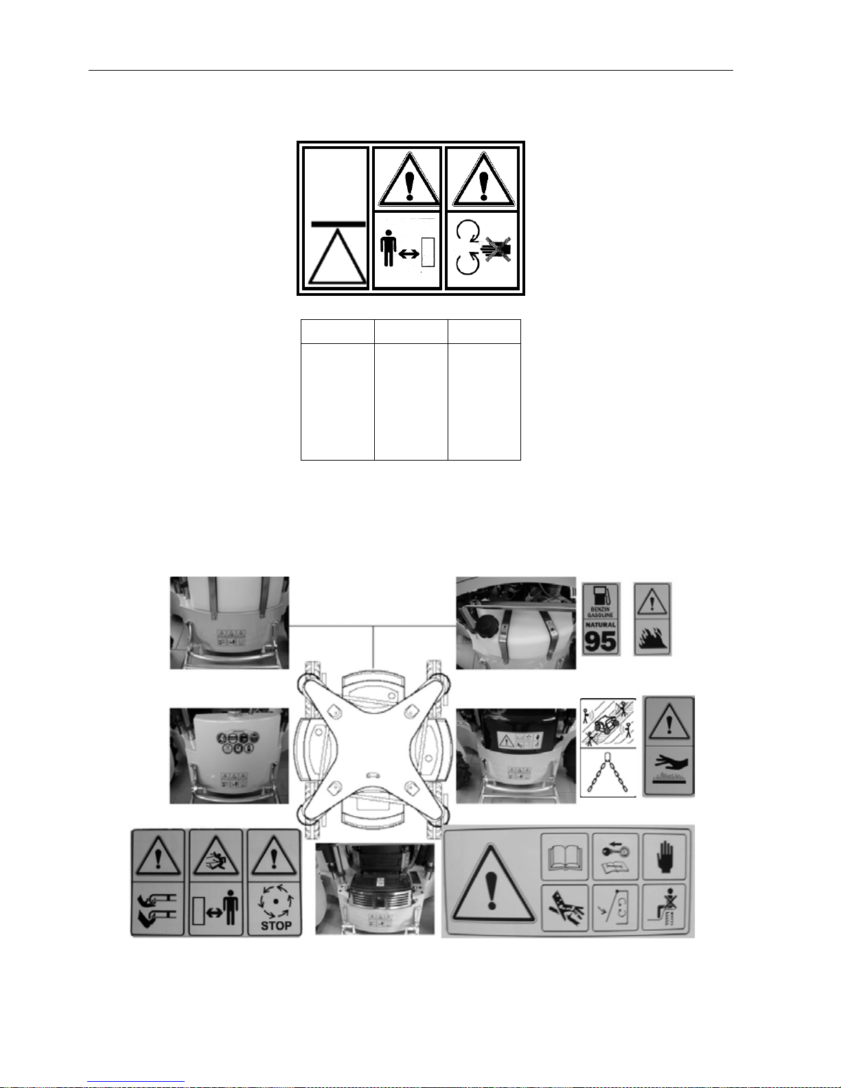
15
16
17
Lifting jack
support point
Keep safe
distance from
the machine
when it is
moving
Attention,
rotating parts
Page 15
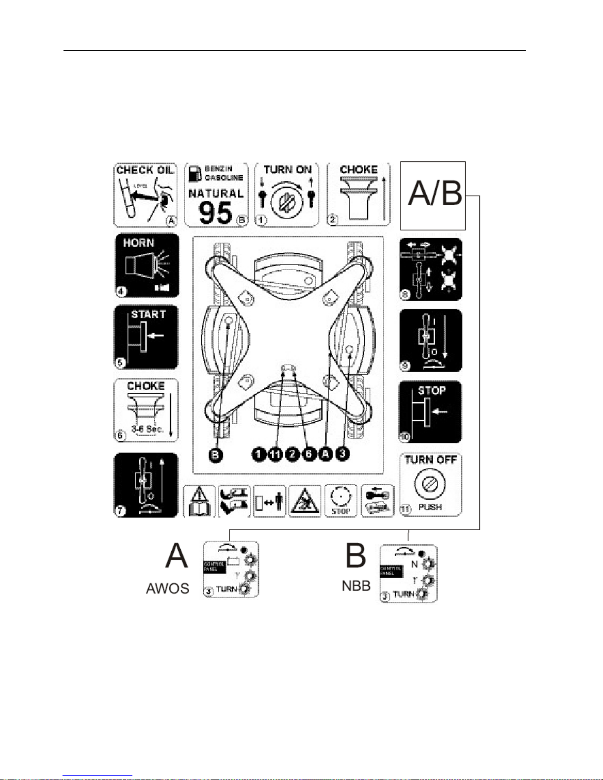
Operation manual - Spider ILD01
15 / 54 rev. 07-01-01-2010
5.1 INSTRUCTION DECALS
Page 16
Operation manual - Spider ILD01
16 / 54 rev. 07-01-01-2010
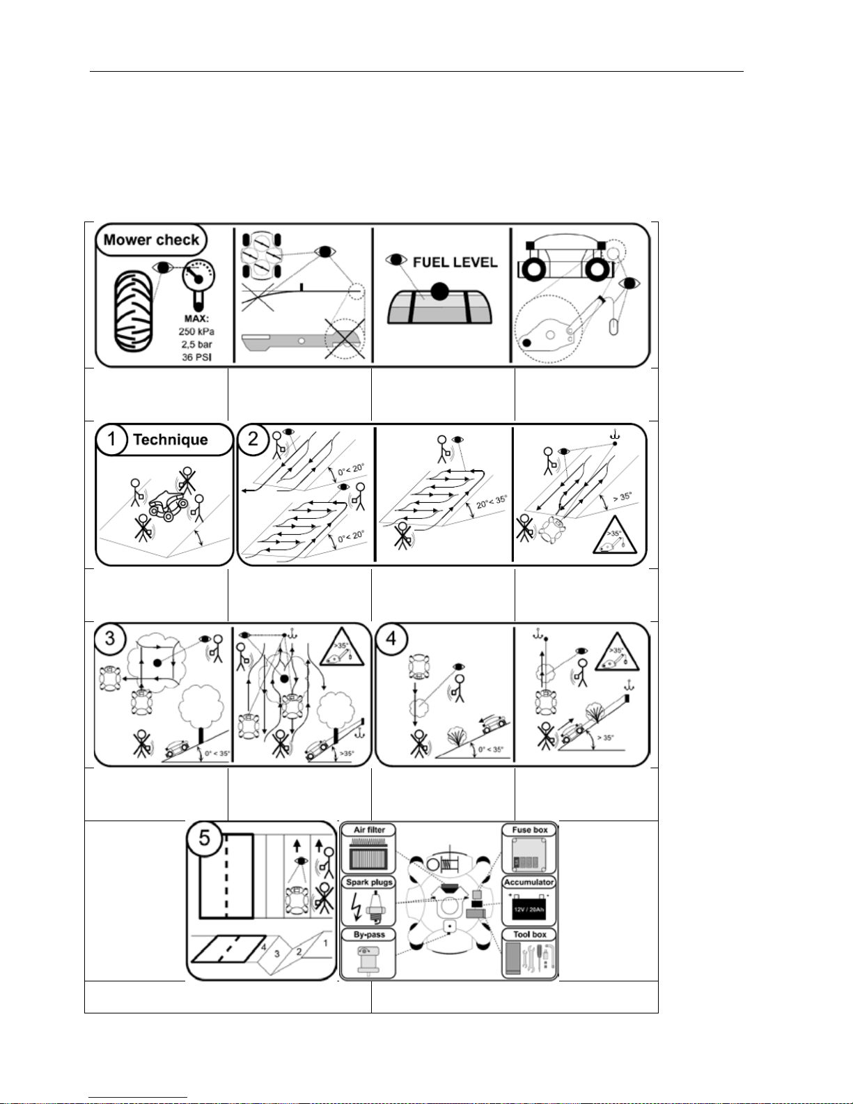
5.1 RECOMMENDED METODS OF OPERATION
This chart shows basic inf ormation about recomm ended methods of cutting gras s in various types of terr ain. It
also describ es the correc t procedure of anchoring th e hydrostat ic stabilizi ng winch. However curr ent terrain and
climatic conditions m ay require different m ethods of operation than those shown in this chart. T he operator is
always responsible for choosing the m ost suitable method of operation especi ally with regards to safety. In an y
case it is always absolutely necessary to comply with all safety instructions listed in this Manual.
Chart of recomm ended methods of operation is placed together with the bas ic set of tools on th e machine. S ee
chapter 11.24 Tools.
Always keep the tyres inflated to the
recommended pressure. Other values
may unfavourably influence the
driving characteristics. Maximum
pressure – 250kPa/2,5bar/36PSI
Check the blades. Blades must be
properly tightened. Blades must not
be bent and the edges must not be
damaged.
Check the fuel level
Check the overall condition of the
winch. The rope and the snap hook
must not be damaged.
On slopes never enter the area below
or directly above the machine.
Recommended method of cutting on
slopes up to 20 degrees provided the
operator is well acquainted with the
terrain and there is no risk of tipping
the machine over.
Recommended method of cutting on
slopes up to 35 degrees provided the
operat or is well acquainted with the
terrain and there is no risk of tipping
the machine over.
On slopes exceeding 35 degrees always
use the stabilizing winch. On slopes
never enter the area below or directly
above the machine.
Recommended method of cutting
around trees on slopes up to 35
degrees.
Recommended method of cutting
around trees on slopes exceeding 35
degrees. On slopes exceeding 35
degrees always use the stabilizing
winch.
Recommended method of cutting
bushes on slopes up to 35 degrees.
Recommended method of cutting
bushes on slopes exceeding 35 degrees.
On slopes exceeding 35 degrees always
use the stabilizing winch.
Recommended method of cutting along roads. Never enter the area below or
directly above the machine. Danger of getting injured by objects thrown by the
blades. Carefully check the terrain in front of the mowe r.
Position of important components on the machine (air filter, spark plugs,
hydraulic by-pass allowing the disengagement of hydraulics and consequent
towing of the machine, fuse box, battery, tools)
Page 17

Operation manual - Spider ILD01
17 / 54 rev. 07-01-01-2010
Instructions for turning on and off the hydrostatic winch
Rotate the machine so that the winch
is facing up the hill toward the
expected anchoring point.
Turn the wheels so that they are
orientated across the slope (along the
slope contours)
Turn off the blades
Reduce the engine RPM to minimum
(idling speed)
On the control panel on the machine
turn on the hydrostatic winch by the
ON-OFF switch.
By pushing the driving joystick
slightly backward the rope will begin
to unwind. Fasten the rope properly
to the anchoring point.
Increase the engine RPM to maximum
Tighten the winch rope by pushing
the driving joystick slightly in the
forward direction.
Turn on the blades
Leave the anchoring position of the
mower by pushing the driving joystick
forward and by driving up the slope.
Method of cutting up and down a
slope: driving up the slope – push the
joystick forward, driving down the
slope – push the joystick backward
Method of cutting across the slope:
Drive according to the picture. The
joystick should always be pushed in
the forward direction..
Place the mower at the bottom of the
slope
Turn the wheels across the slope,
perpendicular to the anchoring point
Turn off the blades
Reduce the engine RPM to minimum
(idling speed)
Loosen the winch rope by pushing the
drive joystick slightly backward.
Untie the rope from the anchoring
point. Wind the rope back onto the
winch drum by pushing the drive
joystick slightly forward.
On the control panel on the machine
turn off the hydrostatic winch by the
ON-OFF switch.
Check the overall condition of the
winch. The rope and the snap hook
must not be damaged.
Page 18
Operation manual - Spider ILD01
18 / 54 rev. 07-01-01-2010
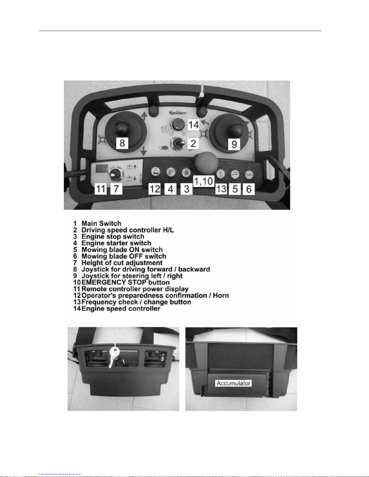
6 CONTROLS
6.1 REMOTE RADIO CONTROLLER NBB
Page 19
Operation manual - Spider ILD01
19 / 54 rev. 07-01-01-2010
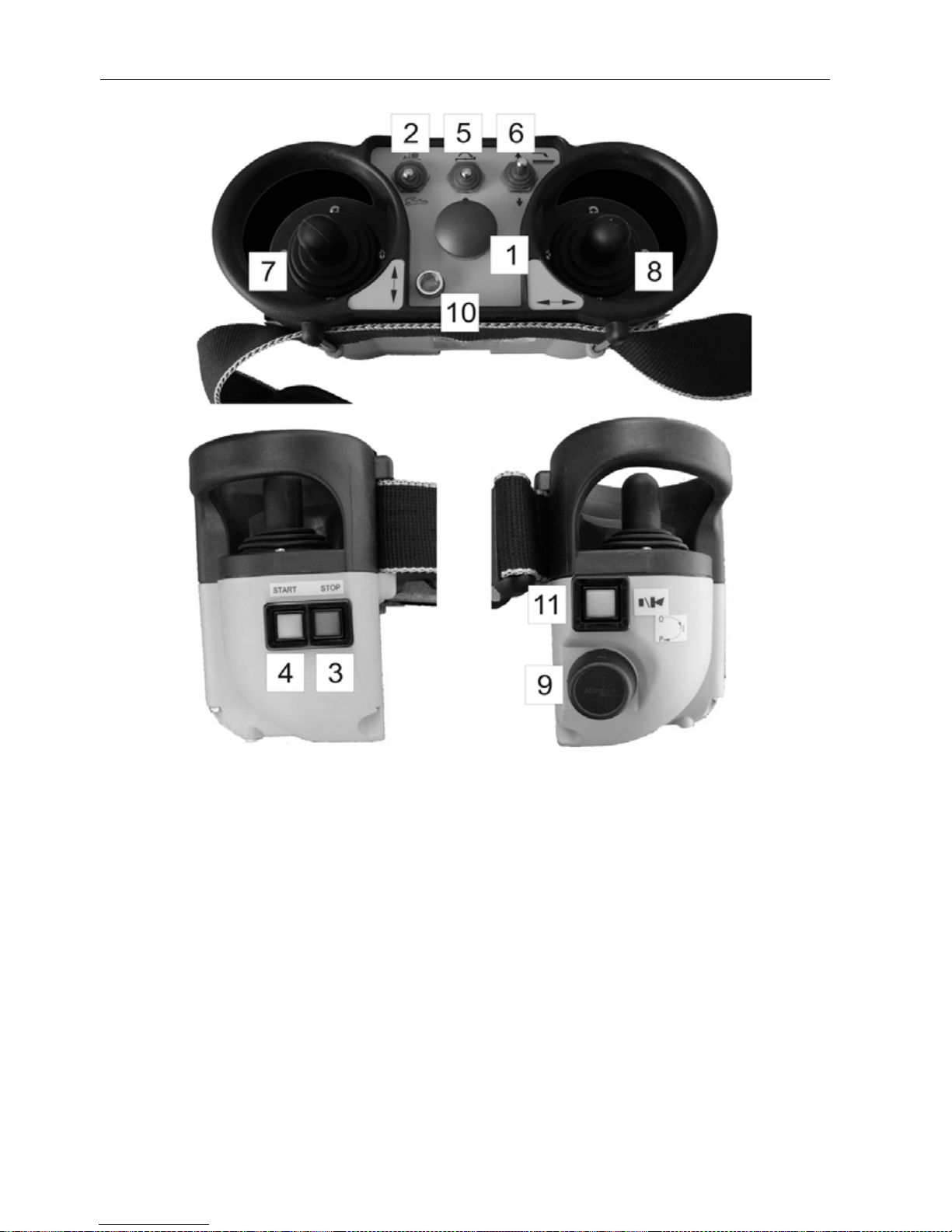
6.2 REMOTE RADIO CONTROLLER HETRONIC
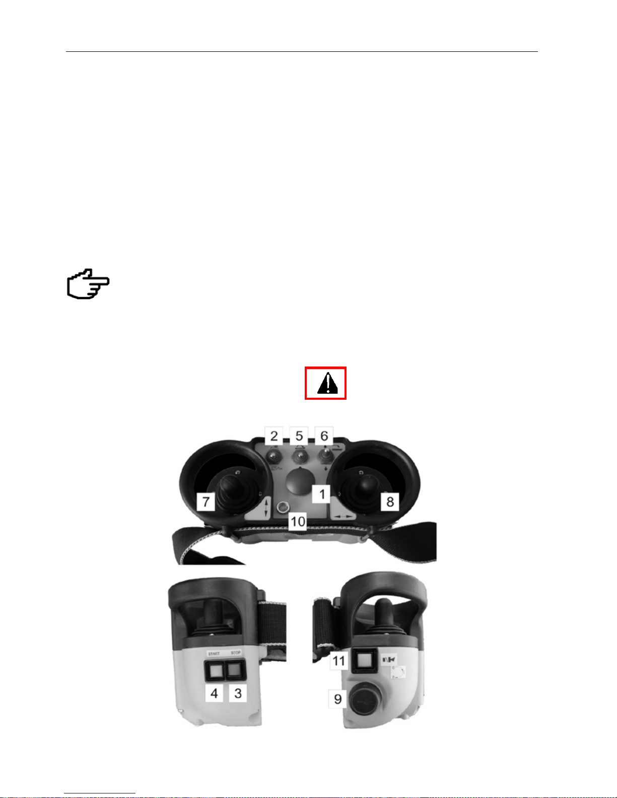
1 EMERGENCY STOP buton
2 Driving speed controller H/L
3 Engine stop switch
4 Engine starter switch
5 Mowing blade ON/OFF switch
6 Height of cut adjustment
7 Joystick for driving forward / backward
8 Joystick for steering left / right
9 Main Switch
10 Remote controller power display
11 Operator’s preparedness confirmation / Horn
Page 20
Operation manual - Spider ILD01
20 / 54 rev. 07-01-01-2010
6.3 MOWER CONTROLS
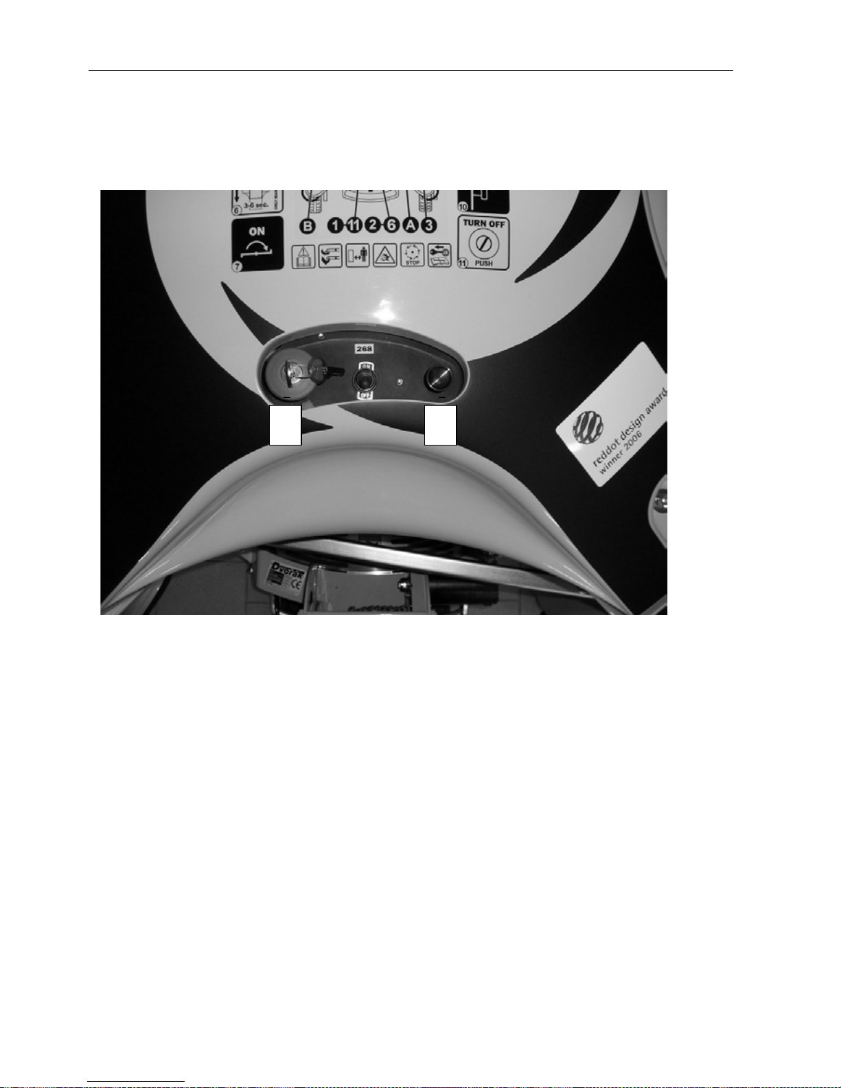
On the body of the mower there are two controls for operating the mower. Additional controls may be added in case
of attaching optional accessories. The function of controls pertaining to these accessories are explained in the
user’s manuals of these devices.
1 Lockable EMERGENCY STOP button / Ignition switch
2 Choke for cold start
1
2
Page 21

Operation manual - Spider ILD01
21 / 54 rev. 07-01-01-2010
7 DISPLAYS
7.1 NBB RADIO CONTROL DISPLAYS
Indicator (11) flasher - Radio Control power on indicator
Radio controll emits a high pitch tone - Radio Control battery low voltage
warning
7.2 HETRONIC RADIO CONTROL DISPLAYS
LED flashes green – Radio Control power on indicator
LED flashes yellow – Radio Control battery low voltage indicator
7.3 MOWER DISPLAYS
AMPV AW 733 AW 891
NBB
1 Power Indi cator 1 Power Indicator 1 Power Indicator 1 P ower Indicator
2 Signal Reception 2 Signal Reception 2 S i gnal Reception 2 Signal Reception
3 Neutral 3 Neutral 3 B attery Charge 3 Neutral
4 Battery Charge 4 Blade 4 Blade 4 Blade
5 Blade
On the cover of the battery there are a number of warning LEDs and an hour meter. Identify the version you
have.
The displays signal the following states:
Power Indicator: Illuminated green when the EMERGENCY STOP on the top of the mower is unlocked.
Beacon is flashing when the EMERGENCY STOP on the top of the mower is
unlocked.
Signal Reception Illuminated green when the radio link between the RC and the receiver is established
and correct.
Neutral: Illuminated green when the transmission is in a neutral position.
Battery charge: Illuminated red when there is a charging fault or when the engin is switched off.
Blade: Illuminated red when the blade is engaged.
1
Beacon (optional)
Page 22

Operation manual - Spider ILD01
22 / 54 rev. 07-01-01-2010
AMPV
NOTICE: if indicator lamp number 4 is illuminated or either of the indicator lamps 1, 2, 3 is dimmed, the mower
cannot be started.
Remedy:
• Indicator lamp number 1 is dimmed – try to turn the key in the ignition again.
• Indicator lamp number 2 is dimmed – try restoring the signal between the mower and the RC by
switching the RC off and on again and by checking the aerial on the mower.
• Indicator lamp number 3 is dimmed - move the forward/reverse joystick and set neutral position of the
hydraulic gear.
• Indicator lamp number 5 is illuminated – set the mowing mechanism clutch engagement /
disengagement controller to the OFF position.
AW 733
After the power supply is turned on, indicator lamp 1 will be illuminated. The following actions take place:
• Initialisation of the processor, check of radio connection and check the communication with the
hydraulic pump servo-motor. If the hydraulic pump servo-motor is in the neutral position, indicator
lamp 3 will illuminate.
• After the radio controller is turned on and communication is established between the machine and
remote controller, indicator lamp 2 will illuminate.
• If the blade magnetic clutch is engaged, it is not possible to start the engine and the horn will sound. It
will require the blade to be turned off on the radio control unit.
• If the mower battery has insufficient charge the horn will sound.
• When the engine is running the batteries are constantly checked, if the battery is exhausted or drops
below 11.7 volts the horn will be sounded repeatedly.
AW 891
After the power supply is turned on, indicator lamp 1 will be illuminated. It will flash for seven seconds, during
this period the following actions take place:
• Initialisation of the processor, check of radio connection and check the communication with the
hydraulic pump servo-motor. If the checks are successful lamp 1 will illuminate. If a malfunction is
detected lamp 1 will flash.
• When there is communication between the machine and the radio control unit, lamp 2 flashes. If there
is a break in communication lamp 2 dims and lamp 1 flashes.
• After the processor is initialised lamp 3 illuminates and a battery voltage is checked. If the battery has
insufficient charge, lamp 3 flashes.
• When the engine is running the batteries are constantly checked, if the battery is exhausted or drops
below 12 volts, lamp 3 flashes.
• While the blade is engaged, lamp 4 is illuminated. The mower cannot be started when this lamp is
illuminated.
NBB
After the power supply is turned on, indicator lamp 1 will be illuminated. It will flash for seven seconds, during
this period the following actions take place:
• Initialisation of the processor, check of radio connection and check the communication with the
hydraulic pump servo-motor. If the checks are successful lamp 1 will illuminate. If a malfunction is
detected lamp 1 will flash.
• When there is communication between the machine and the radio control unit, lamp 2 flashes. If there
is a break in communication lamp 2 dims.
• Lamp 3 is illuminated when the drive servomotor is in a neutral position.
• Lamp 4 is illuminated while the blade is engaged. The mower cannot be started while this lamp is
illuminated.
Page 23

Operation manual - Spider ILD01
23 / 54 rev. 07-01-01-2010
8 SAFETY SYSTEMS
8.1 MOWER SAFETY SYSTEMS
The product is controlled b y a rem ote radio c ontrol ler. This m eans that the o perat or is not c lose to t he m ower at
all times and cannot use contr ols on the mower. For the safety of the oper ator and other pers ons the following
table lists various situations and actions:
The mower is out of the signal range.
The EMERGENCY STOP command is
automatically generated.
Radio signal failure.
The EMERGENCY STOP command is
automatically generated
Another machine with the same frequency
is working in the vicinity.
The EMERGENCY STOP command is
automatically generated.
Emergency situations - shutting off by the
emergency st op butto n.
Push the EMERGENCY STOP button on
the radio controller.
Push the EMERGENCY STOP button
on the body of the mower.
Safety Interlocks prevent the engine
from starting.
If the mowing blade clutch is engaged.
If the transmission is not set to a neutral
position.
If the radio connection is not
established properly.
The EMERGENCY STOP command (automatic or manual) has the following effects:
1. Engine stops
2. Steering of wheels is blocked
3. Travelling is blocked
4. Starter is blocked
5. Mowing blade clutch disengages
6. Ignition is turned off
Page 24

Operation manual - Spider ILD01
24 / 54 rev. 07-01-01-2010
9. PREPARING THE MACHINE
9.1 MACHINE DELIVERY TO A DEALER
OR RETAILER
From the manufacturer the machine is
delivered filled with engine oil and
hydraulic oil but without gasoline in the tank.
The training of the o perator should tak e place during
the installation of the product.
The mower may be delivered on a wooden pallet or in
a crate.
To take the mower off the pallet
• Place the palette with the mower on a level
surface
• Carefully remove the upper boards of the
crate and take out all accessories & the
remote control Disassemble the side boards
of the crate
• Release the attachment fastening the
mower to the pallet, remove transportation
wrapping. Recycle these wraps.
• Thoroughly examine the mower for possible
damage and missing parts from the
delivery. If necessary, contact the
transporting company with your claim.
• Before driving down from the pallet raise the
mowing mechanism to the upper position
(this can be done without starting the
engine)
• Place boards in front of the wheels in the
direction, in which you expect to drive the
mower from the pallet to the ground. Put at
least 5 litres of fuel to the tank and attach
cables onto the battery. While starting,
follow instructions in chapter 5.
• The aerial must be attached to the mower
• After starting the engine set the speed
controller on the transmitter to the (L)
symbol – lower driving speed
• Slowly move the forward/reverse joystick to
correspond with the direction you want to
move the mower. The arrow on the wheel
legs indicates forward.
• Slowly drive down to the ground and stop
the engine
• While unpacking, assem bling and preparing
the mower, do not engage the mower blade.
Součásti dodávky:
• SPIDER mower
• Mower ignition key (X2)
• Gel battery (12v starting)
• Remote control including 2 batteries
• Remote control battery charger (12v – 12v)
• Operation manual
• Radio controller key (X2)
• Engine user’s and maintenance manual
• RC instruction manual
• Copy of the EC declaration of conformity
• Copy of the EC declaration of k onformity for
Remote controller NBB
If you have a lifting device with a
sufficient lifting capacity
available, place the lifting
hooks/eyes on spots m ark ed with t he s ymbols
of chain, lift the load by about 0,15 m (6inch),
move the pallet away from the mower and
lower the machine to the ground.
There may not be enough f uel in
the fuel system when start ing for
the first time and you may need
to repeat the starting several times. Starting
period must not exceed 3 seconds. There
must be a pause of at lest 20 seconds
between all attempts to start the engine.
Page 25
Operation manual - Spider ILD01
25 / 54 rev. 07-01-01-2010
9.2 GEAR-BOX BY-PASS
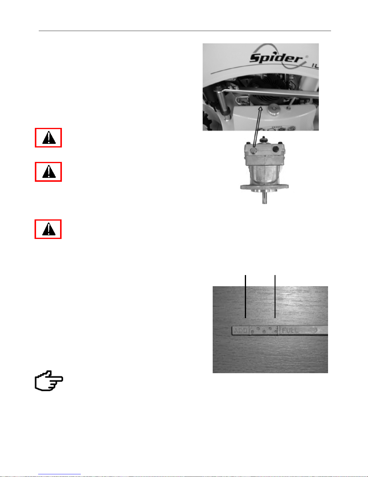
The By-pass is used to disabl e the hydraulic dr ive and to
engage the oil bypass for manual handling (engine not
running) of the machine on flat surfaces. The by-pass
should only be used when the hydraulic drive is not
functional. For normal hydraulic drive it is necessary to
have the bolt on the pump tightened. For manual
handling loosen this bolt by two revolutions.
Before starting, check the bolt tightness. If
loose, it will disable the hydraulic drive.
Insufficient tightening may result in undesirable
behaviour of the mower on slopes. It may
uncontrollably drive down a slope.
9.3 CHECKING ENGINE OIL LEVEL
Attention! Before checking or refilling oil stop the
engine and let it cool down.
The oil level of the machine standing on a level surface
must be between the limit marks on the dipstick (see the
engine user’s manual). Ch eck oil according to the engine
user’s manual as follows:
1) Place the machine on a level surface.
2) Remove the upper body
3) Unscrew the dipstick and wipe off oil.
4) Without screwing inset the dipstick back into the filler
as far as you can.
5) If the oil level is close or under the lower limit mark
(ADD), fill with recommended oil up to the upper limit
mark (FULL).
6) Refit the dipstick.
Running the engine with insufficient oil may
cause serious damage to the engine.
Check the eng ine oil level on a le vel surface and
only when the engine is off.
Use only oil recommended by the engine
manufacturer.
min max
Page 26
Operation manual - Spider ILD01
26 / 54 rev. 07-01-01-2010
9.4 CHECKING HYDRAULIC DRIVE OIL LEVEL
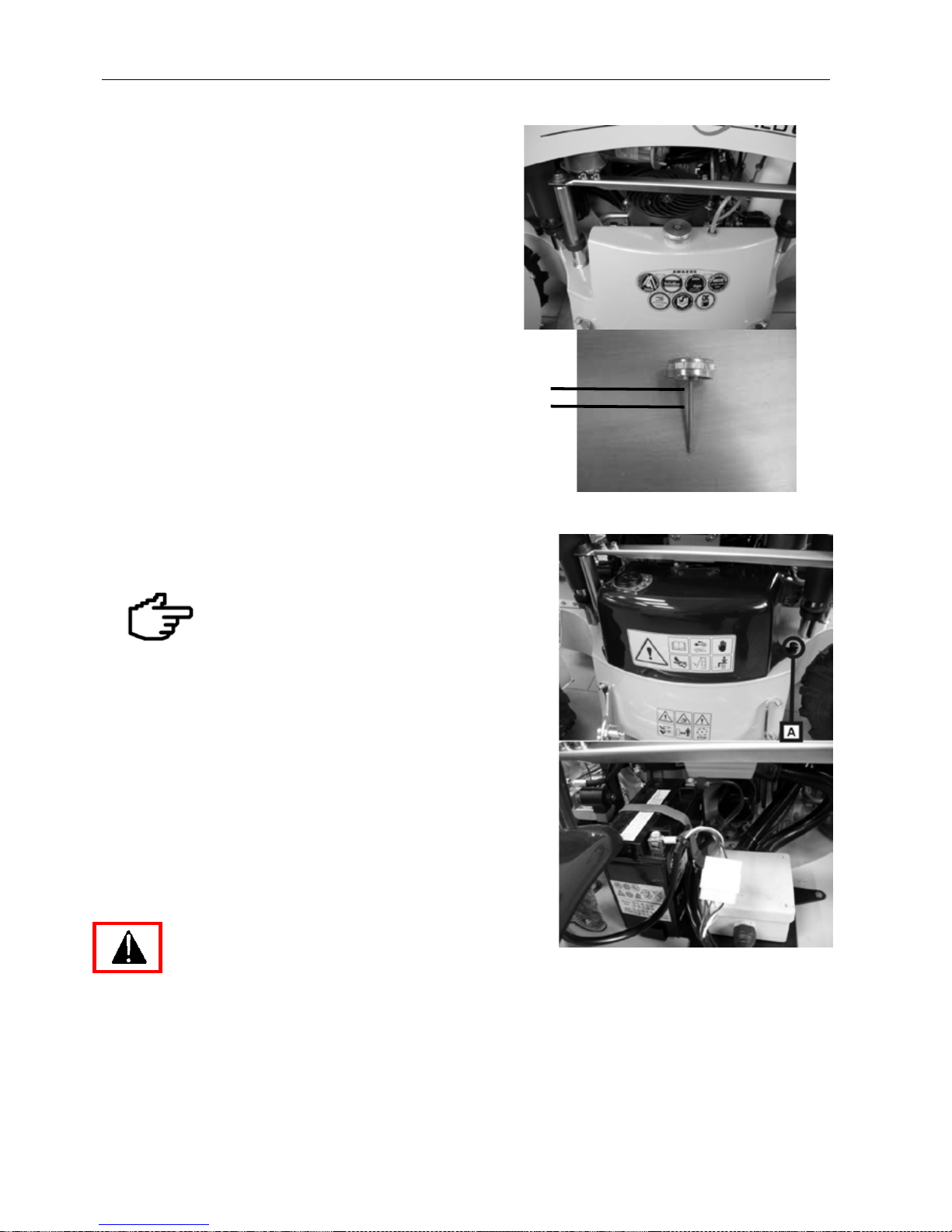
Oil level should only be checked when the oil is cold.
Clear debris from around the cap, unscrew the
cap on the hydraulic oil tank on the side of the
mower.
Using the dipstick check the oil l evel. It m ust be
between the limit marks.
If the level is above this range, the oil may
overflow from the breather pipe in the tank
when hot. If the level is below the lower limit,
the hydraulic drive may be damaged.
Refill w ith oil if necessary (HM 68 according to
ISO 6743 or HLP 68, CL P 68 according to DIN
51502).
When finished, refit the cap back on the oil tank.
9.5 PREPARING THE BATTERY
SPIDER ILD – 01 mower u s es a gel battery model 6E12,
12 V, 18 Ah
Do not fill the battery with electrolyte! The
machine construction uses a dry type of
battery. If recharging, use a maximum electric
current of 1,4 A.
Unscrew the thumb wheel (A) and move aside the
battery cover (see the figure).
Remove/insert and fasten the battery
Attach the terminal connectors according to polarity.
First (+) then (-).
Secure the battery against movement with a rubber band.
Screw back the battery cover.
When disconnecting a nd removing th e battery, proc eed
in reversed order.
NEVER START THE M OWER W HEN A
CHARGER I S CO NNECTED TO T HE
BATTERY.FOR CH ARGING US E O NLY
SPECIAL C HARGERS P REVENTING T HE
EXCESS O F T HE G ASSING VO LTAGE. WHEN
CHARGING T HE BATTERY, M AKE S URE T HAT
CABLES CO NNECTING T HE BATTERY TO T HE
MOWER ARE DI SCONNECTED.
min
max
Page 27
Operation manual - Spider ILD01
27 / 54 rev. 07-01-01-2010
9.6 FUEL TANK
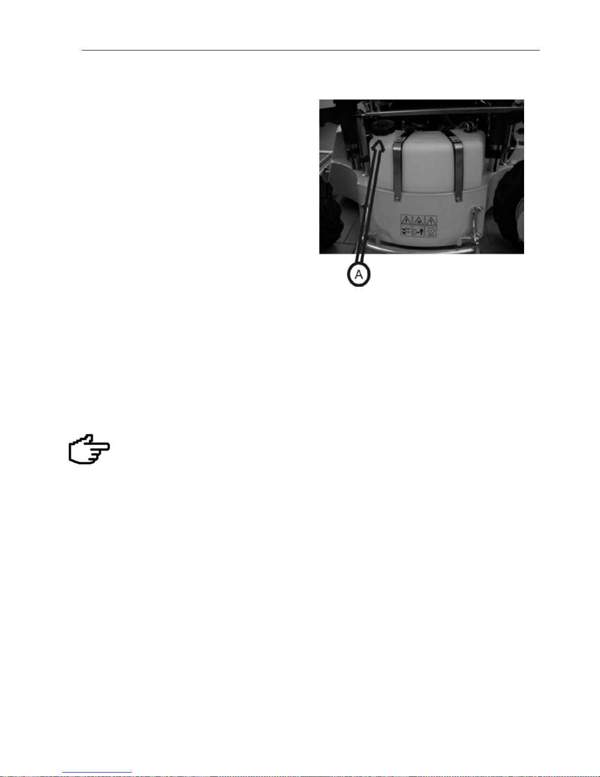
The plastic fuel tank is placed on top of the m ower
deck, to one side of the mower. The tank has a
screw-on cap A.
Before refuelling always stop the engine. Do not smoke
or approach open flames or sources of sparks when
manipulating with gasoline.
Use unleaded 95-octane gasoline without any additives.
The operator is responsible for all engine or fuel system
damage resulting from the use of wrong, low-class, old
or contaminated fuel. The warranty does not extend to
such damage.
Do not fill the tank near open flames or sources of
ignition. Do not smoke.
Do not open t he tan k while i t i s hot.
Do not fill/empty the tank in enclosed areas.
9.7 PREPARING THE NBB REMOTE RADIO CONTROLLER
Insert the original batte ry (Ni-Cd 7.2V, 1500 mAh) into the remote radio controller. If the power indicator flashes, the battery is
charged.
Discharge s ignal – if the voltag e of the remote radio contr oller is too low, then the RC will emit a high pitch soun d.
Move the mower to a safe place and replace the battery. After the low voltage is indicated, you have about 15 minutes
to move the m ow er to a saf e plac e. After 15 m inutes th e rem ote r adio c ontr oller wi ll be turn ed of f perm ane ntl y. If the
battery is exhausted, replace it with a reserve battery.
The transmitter (remote radio controller) and the receiver (control unit) were adjusted and set-up by the
manufacturer. Do not make any modifications to these devices. They are a matched pair.
9.8 CHARGING THE NBB REMOTE RADIO CONTROLLER BATTE RY
To charge the battery:
Connect the charger to the electric power out let in your car. Ins ert the battery into the char ger (orange lamp is
illuminated and the battery charging starts).
When the battery is fully charged, the orange lamp flashes quickly.
Leave the battery in the charger as long as necessary (the charger controls the charge level and does not overcharge the
battery)
Page 28

Operation manual - Spider ILD01
28 / 54 rev. 07-01-01-2010
9.9 PREPARING THE HETRONIC REMOTE RADIO CONTROLLER
Insert the battery (type 3,6V NiMh, 1200mAh) into the remote radio controller.
If LED flashes green, the battery is charged.
If the remote radio controller battery voltage is below the required level, the entire machine will turn off
automatically.
Discharge signal – if the voltage of the rem ote radio controller ba ttery is too low, the colo ur of the LED on the
remote radio controller changes (LED flashes yellow). Move the mower to a safe place and replace the
battery. After the low voltag e is indic ate d, you h av e ab out 10 minutes to move the m ower to a safe place. After
10 minutes the remote radio controller will be turned off permanently. If the battery is exhausted, replace it with
a reserve battery.
The tr ansmitter (r emote r adio controller) a nd th e r eceiver (c ontrol u nit) w ere a djusted a nd
set-up b y th e manufacturer. D o n ot m ake a ny m odifications to th ese d evices. T hey a re a
matched pair.
9.10 CHARGING THEHETRONIC REMOTE RADIO CONTROLLER BATTERY
To charge the battery:
Connect the charger to the electric power outlet in your car.
Insert the battery into the charger (LED CHARGE flasher for 2 seconds and then shines during charging).
Leave the battery in the charger as long as necessary (the charger controls the charge level and does not
overcharge the battery).
Fast charge – after connecting the battery press the FAST CHARGE button.
When the battery is fully charged, the green LED READY shines.
10 OPERATION
10.1 TRANSPORTING THE MOWER
The mower should be transported to the mowing area on a trailer or
other suitable transport vehicle.
Transporting the mower on thoroughfares on its own wheels is
prohibited
When loading/unloading a trailer, make sure that the edge - formed by
the floor of the trailer and the ramps – is not an obstacle for the mower.
Otherwise you need to use longer ramps.
When loading, do not allow any person to stand by the ramps or under
the hanging mower if it is lifted. It may only be hung up
on places marked by the chain symbol. The loading capacity of the
lifting eyes/ hooks must be suitable for the weight of
the machine as quoted on the serial plate.
After placing the mower on the transport, make sure it is properly
secured. Attach f astening devices to the eyes marked by the chain
symbol on the mower.
Page 29
Operation manual - Spider ILD01
29 / 54 rev. 07-01-01-2010
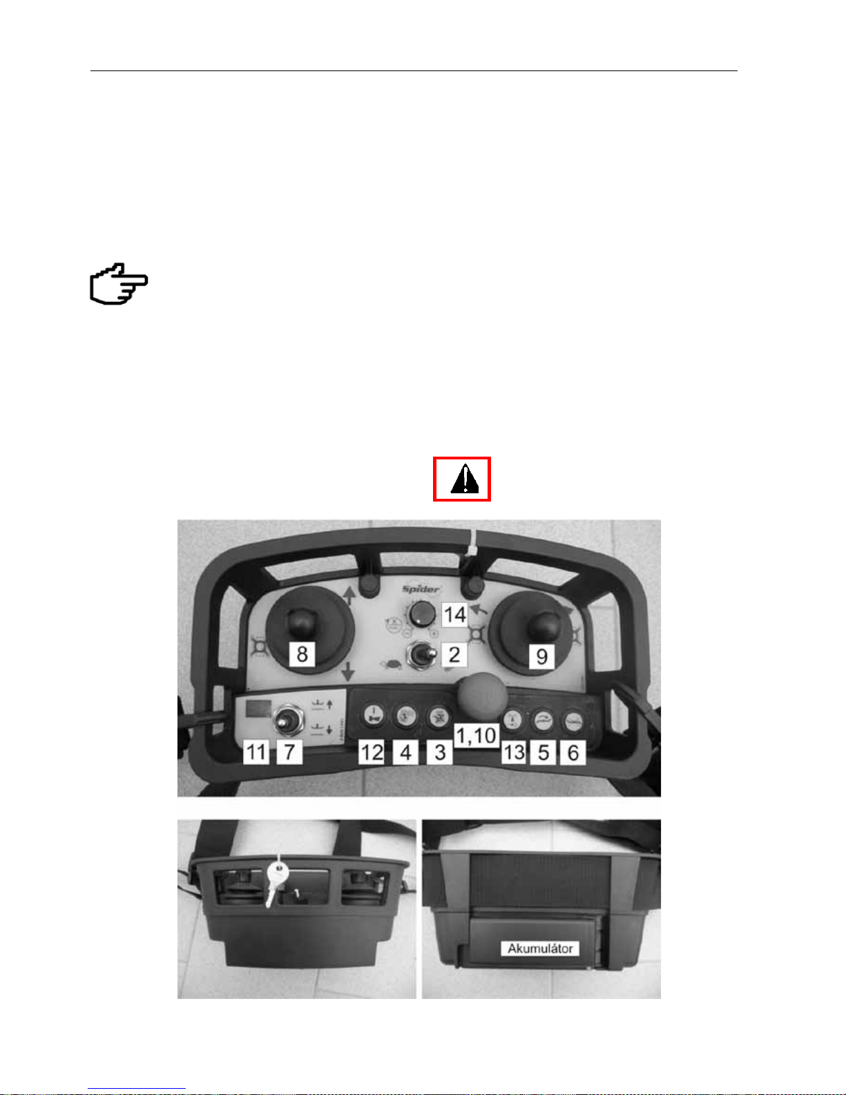
10.2. STARTING THE ENGINE OF THE MOWER WITH THE NBB REMO T E CONTROL
• Check the gasoline in the fuel tank, refuel
with unleaded gasoline BA95 if
necessary.
• Chec k the f orward/re verse contr ol jo ystick
(8 on the remote radio controller and
leave it the neutral position .
• Switch ON the remote radio controller
power switch (1) by turning clockwise.
• A red lamp (11) will illuminate on the RC.
Unless b utton (1 ) i s in th e O N
position, the machine will not start
• Ensure the EMERGENCY STOP button
(1) on the remote radio control is in the
raised position.
•
Set the engine choke control to the
position for cold start - the lever is pulled
up (only for the first start or if the engin e is
cold). See the engine user’s manual.
• Use the key to unlock and pull up the
EMERGENCY STOP button on the
mower.
• Wait till lamps 1 and 3 are illum inat ed and
lamp 2 is flashing (on the mower), then
press the horn button (12) on the remote
radio controller – the mower ignition
engages.
• Press the START button (4) on the
remote r adio controller . If the engine does
not start, all the functions of the mower
are locked again. To unlock them and
consequently to start the engine, press
button (3).
• The engine is “running”, release the
START button on the remote radio
controller. While the engi ne is working do
not use the START button again.
• Let the mower idle for about 2 – 3 minutes
without engaging the m owing device and,
while the engine is warming up, push
back the choke control (in the case of a
cold start)
NOTICE:
Do not stand right next to the mower while
starting it
Page 30
Operation manual - Spider ILD01
30 / 54 rev. 07-01-01-2010
10.2. STARTING THE ENGINE OF THE MOWER WITH THE HETRONIC REMOTE
CONTROL
• Check the gasoline in the fuel tank, refuel
with unleaded gasoline BA95 if
necessary.
• Check the position of the blade drive lever
switch (5) on the remote radio controller.
The controller must be in the OFF
position.
• Check the forward/reverse control joystick
(7 on the remote radio controller and
leave it the neutral position .
• Switch ON the remote radio controller
power switch (9) by turning clockwise.
• The controller will beep after a few
seconds and lamp 10 will illuminate.
Unless switch 5 is in the OFF position,
button 9 in the ON position and the
EMERGENCY STOP button in the
raised position, the machine will not
start.
• Ensure the EMERGENCY STOP button
on the remote radio control is in the raised
position.
• Set the engine choke control to the
position for cold start - the lever is pulled
up (only for the first start or if the engine is
cold). See the engine user’s manual.
• Use the key to unlock and pull up the
EMERGENCY STOP button on the
mower.
• Wait till LED number 2 on the mower
starts to shine (about 10 seconds).
• Press the horn button on the remote radio
controller – the mower ignition engages.
• Press the START button (4) on the
remote radio controller.
• The engine is “running”, release the
START button on the remote radio
controller. While the engine is working do
not use the START button again.
• Let the mower idle for about 2 – 3 minutes
without engaging the mowing device and,
while the engine is warming up, push
back the choke control (in the case of a
cold start).
• For 5 seconds after the engine has
started all motion functions of the mower
are blocked – they can be unblocked by
pressing the horn button 11.
NOTICE:
Do not stand right next to the mower while
starting it
Page 31
Operation manual - Spider ILD01
31 / 54 rev. 07-01-01-2010
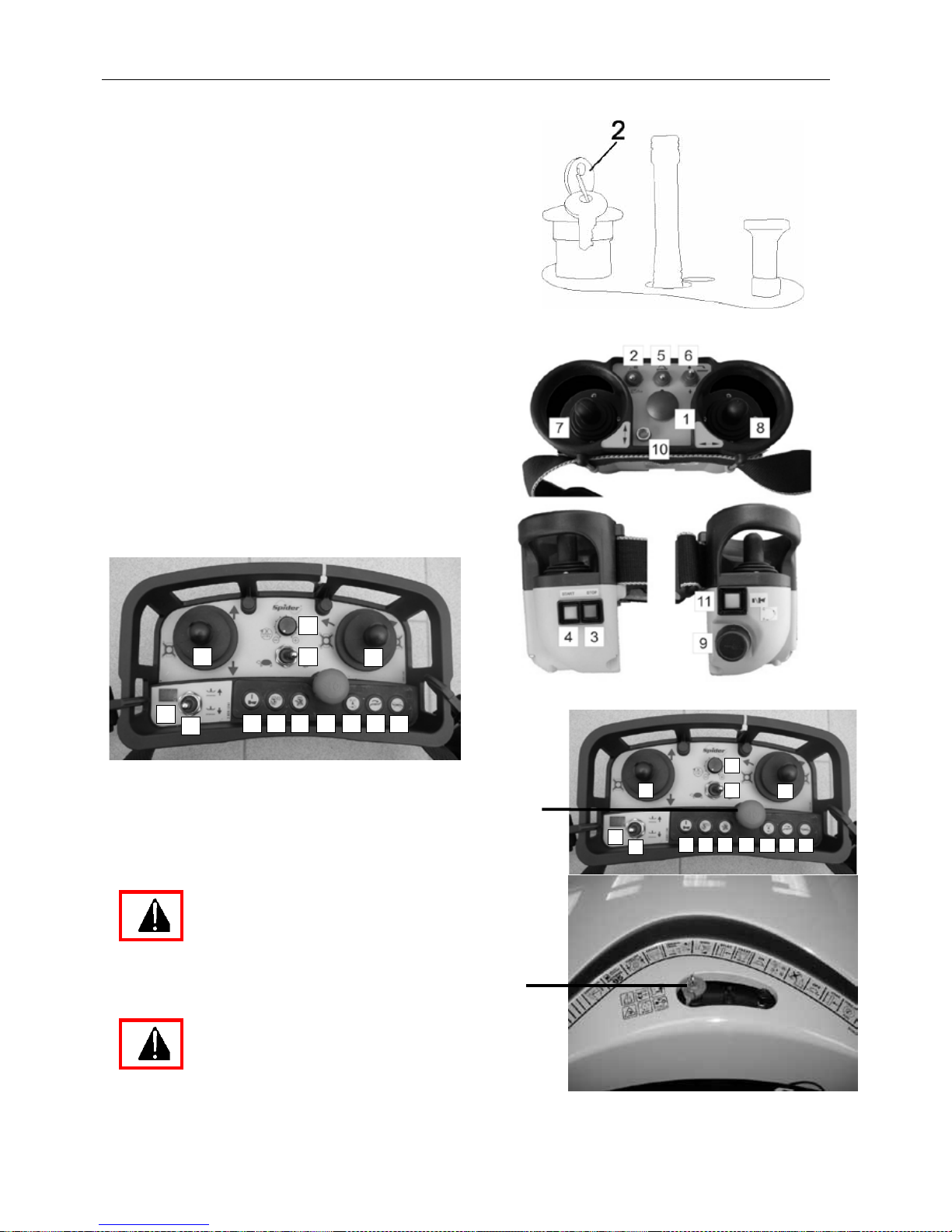
10.3 SHUTTING OFF THE ENGINE
• Before shutting off the engine, always
disengage the mowing mechanism drive on
the remote radio controller.
• Do not shut the engine off immediately after
mowing, let it run for a short while with the
minimum engine speed in order to let it cool
down.
• Stop the engine by pushing the STOP button
(3) on remote radio controller.
• Do not use the EMERGENCY STOP button
to shut off the engine except in an
emergency.
• Press the EMERGENCY STOP (2) button
on the mower and remove the key.
• HETRONIC - Turn off the remote radio
controller by turning the key (9)
anticlockwise. The key may be removed if
desired.
• NBB - Turn off the remote radio contr oller b y
pushing button (9).
NBB - RC
HETRONIC - RC
11
7
12
8 2
14
9
4 3
1
13
5
6
10.4 EMERGENCY SHUTTING OFF OF THE ENGINE
There are two red EMERGENCY STOP buttons.
One is placed in the remote radio controller (1), the
other one on the body of the mower (2). Both
buttons have the same function.
For emergency stopping use preferably
the remote control button (1). Use the
button on the mower (2) only when the
mower is in a stable position and on a flat
area, or when you are standing right next to the
mower and cannot be endangered by the machine.
The EMERGENCY STOP bottons on the
remote radio c ontrol (1) and on th e
mower (2) should be used at any time
when an emergency stop is required.
2
11
7
12
8 2
14
9
4 3
1
13
5
6
Page 32
Operation manual - Spider ILD01
32 / 54 rev. 07-01-01-2010
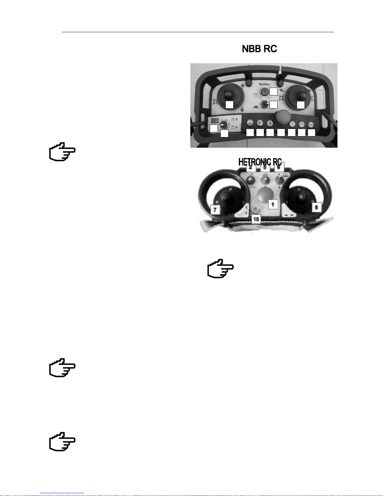
10.5 ENGAGING THE MOVING BLADES
The mowing blades can only be engaged when the
engine is running.
Set the maximum mowing height with switch (6).
Move the switch (5) of the blade-drive clutch to the
ON position on the remote radio controller (NBB RC:
firts increase engine speed by regulator 14) – the
mowing device engages after four seconds .
Set the working position of the blade b y the mowing
height switch (6) on the remote radio controllerhetronic rc, (7)-NBB - rc
Do not engage the mowing blades in tall
grass, damage to the clutch ma y result. If
you wish to mow tall grass, move the mower
to a place without tall grass and then turn
the blades on. When engaging the blades stand in a safe
distance from the mower. Do not engage the blades if
there are people near the mower. The rotating blades may
throw objects.
10.6 DISENGAGING THE BLADES
Move switch (5) blade drive to the OFF position –
the mowing device disengages (NBB: press button
13 to disengage the blade). If you are not planning
to mow anymore, set the maximum height with
switch (6) on the rem ote radio contr oller –Hetronic rc,
(7)-NBB rc.
10.7 HEIGHT OF CUT ADJUSTMENT
The machine has a variable mowing height. The
mowing height can be from 60 to 110 mm as a
standard.
The mowing height can be adjus ted by switch ( 6) on
the remote radio controller Hetronic rc, (7)-NBB rc.
Follow the marks on the body of the mower.
If the grass growth is high or wet, select a higher
mowing position.
The lowest position is used when mowing wellmaintained and even areas.
when mowing unknown areas for the
first time, we recommend to m ow with
blades in a higher position and - after
finishing mowing - to re-examine the
area for undesirable objec ts. The next
cut should
only be done after the grass cuttings have died.
Set the hei ght of cut ap proxim ately, mo w a few meters
of the area and check that t he height of the c ut grass
meets you expectations.
The height of cut on a slope may
significantly vary from that on a level
surface.
Switch (6)-Hetronic, (7)-NBB has 3
positions: The maximum and
minimum limit position and the third
intermediate position, which preserves
the current height set-up.
Cleaning the mowing mechanism
After each use the mowing mechanism must be
carefully cleaned, espec ially the inner walls of the
mowing deck. The clea ning should be carried out
with a scraper. The m ower must not be washed b y
power washer or other high-pressure devices.
When cleaning, secure the machine against
moving.
Raise the mowing mechanism to the transporting
position. When cleaning, also check the blades.
Proper maintenance and tr eatment of the mowing
mechanism increases the quality of work and
durability of your machine.
After cleaning and dr ying, especially if the mower
will not be used for a longer time, treat all
scratched parts with preservat ive coat in g.
If you are lifting the mower during cleaning, make
sure that you secure it against movement and fall.
Remove t he sp ar p lug t erminal an d p ress t he
EMERGENCY STOP button on the mower.
11
7
12
8 2
14
9
4 3
1
13
5
6
Page 33

Operation manual - Spider ILD01
33 / 54 rev. 07-01-01-2010
10.8 DRIVING THE MACHINE
The machine movem ent is controlled by joystick
(7) (forward and reverse) (see the symbol under
the controller on the rem ote radio controller) and
by joystick (8) (Left/ right). By combining these
two controls you will be able to control the
machine.
When these joysticks are moved, the machine
either accelerates or steers.
NOTICE:
Accelerate slowly so as t o be able to
react to the direction in which the
mower starts to move. T he V shaped
tread pattern on the tyres denotes the direction
the machine will move when forwards motion is
selected.
When driving, slowly move the joystick in the
desired forward or reverse direction.
When changing the forward motion to reverse
motion, always leave the joystick for a short
moment in the neutral positron.
When dr iving the mower, always set the
maximum eng ine speed. Driving wi th any
lower engine spee d is prohibite d.
In cold weather let the e ngin e run f or abou t 2 m inutes
to allow the oil to get warm before driving.
10.9 DRIVING SPEED OF THE MOWER
Always choose a suitable driving speed, which
enables an acceptable mowing quality. When
selecting speed, always start with slow and
proceed to fast, not the other way around. If the
growth is thin, you may mow at higher speed.
To control the driving s peed you can also use the
driving speed contro ller (2), which let’s you choose
between high (rabbit) and low (turtle) driving
speeds. When startin g to operate, always use the
low (turtle) speed range. Also choose the low
speed range when mowing either slopes steeper
than 20 degrees or an uneven terrain.
Never reduce the driving speed by
reducing th e e ngine s peed!!! Always
use joystick (7) to reduce the speed.
Higher speed range: 0-7 km.h1, 0-5 mph
Lower speed range: 0-3 km.h
1
0-2 mph
IT I S P ROHIBITED to drive on slopes
steeped than 20 degrees with the mowing
device engaged and the controller switched to
the high-speed (rabbit) position.
IT IS PROHIBITED to switch to the high-
speed position while mowing. Stop the
machine befor e selecting a different s peed
range.
Page 34

Operation manual - Spider ILD01
34 / 54 rev. 07-01-01-2010
10.10 DRIVING ON SLOPES
Driving o n s lopes i s v ery d emanding fo r th e
operator, as th ey constantly h ave to e valuate
information about the movement of machine
and th e c haracter o f t he terrain. E specially
important is the wheel adhesion to the grass or
other surface and the mower tilt angle. Pay
attention to c limatic c onditions. The c limbing
ability o f th e m ower w ill b e r adically d ifferent
on dry, wet or moist grass slopes.
The mower may work on the
recommended slopes (s ee chapter 2.2)
only when the surface ( grass) is dry. If
the grass is wet or moist, the maximum slope, on
which work is permitted, is 20 degrees.
Examine closely the working area. Evaluate the
situation and test the possibilities and
characteristics of the specific terrain. Do not take
chances. If the mower loses trac tion, you have lost
control, stop mowing and re-evaluate the
conditions.
The driving wheels of the mower must be evenly
inflated to the max imum value allowed by the tyre
manufacturer. Maximal 250 kPa / 2,5 bar / 36 PSI
Start your work at the bottom of the slope and
proceed to the top. This way you will be usually
moving from less to m ore steep slopes, which wil l
give you a better chance to evaluate the climbing
ability and make the right decisions concerning
further work. If you begin to mow steeper slopes
first, it may happen that – due to adverse
conditions - the mower will slip on the slope. Due
to dynamic effects the mower may even roll over.
If the mower is slipping, do not try to stop it and do
not approach it, especially the area below the
mower.
Do not touch or approach the mower if the wheels are
lifted, the mower tilted, in an unstable position or
starting to rol l over. The m ethod of cutting from
the top of the hill to the bottom should o nly be
used exceptionally when the operator is in
detail acquainted with the terrain.
Before operating on s lopes, make s ure that no
one is below the m ower or the working area .
Do not endanger third persons by the
movement of the mower.
Choose your operating positi on away from the
area to which the mower ma y slide or to which
the mowed grass may be thrown. The
direction of the discharged grass may change
while operating according to the driving
direction of the mower.
When working on slopes, avoid the
following:
• Sudden sharp acceleration, steering or
braking
• High driving speed
• Uneven ground
• Changing adhesion (moving from areas
exposed to sun to shade)
• Driving over the mowed material
• Reduction of engine spee d
• Stopping on a slope and shutting off the
engine.
10.11 STOPPING THE MACHINE ON
A SLOPE
In case you are f orced to stop the m ower on a
slope and need to interrupt you work, stop the
engine etc. be sure to position the wheels across
the slope. T his will prevent poss ible movement
of the mower down the slope.
Page 35

Operation manual - Spider ILD01
35 / 54 rev. 07-01-01-2010
11 MAINTENANCE AND LUBRICATION
11.1 MAINTENANCE CAHRT - MOWER
Machine Maintenance Plan
Period according to the state of the operating hours (OH) counter
X = Operator
Daily before
operating
Every
50 OH
Every
200 OH
Every
800 OH
Visually check for oil leakage from engine and
hydraulic systems
x
x
Grease all sliding bars (at least once a season)
x
Lubricate other lubrication points with dry lubricant in
a spray
x
x
Check the level of hydraulic oil in tank
x
x
Check the tyre pressure
x
x
Visually check the tension of travel V-belts
x
x
Visually check the tension of the steering chain
x
x
Check the remote control battery state of charge
x
Check the mower battery state of charge
x
Check electronic and safety devices (emergency st op,
steering, signal etc.)
x
x
Check screw and nuts tightening (visually check daily)
x
Check blade sharpness and deformation
x
x
Check the blade bolts tightening
x
Change the hydraulic oil
x
Change the hydraulics filter
(Ecological oil - first exchange after 200 OH)
x
Rinse the fuel tank, change the breather filter
x
Change the fuel filter (
change more often on extremely
dusty or dirty conditions)
x
Clean cooling systems (engine, hydraulic pump)
Visually check hydraulic hoses, fuel hoses, cables –
replace if necessary
x
Check and adjust wheel geometry
x
Adjust t he ne utral pos ition of t he m achine dr ive
(hydraulic pump)
x
Check, ad just an d t ighten ch ains i n t he wheel
suspensions
x
Adjust the blade deceleration
x
Check d rive b elts an d m owing m echanism b elts –
replace if necessary
x
Check an d cl ean t he mowing mechanism g ear ( belts,
pulleys, belts pulleys)
x
Check safety decals on the machine
x
Check the mowing device bearings
x
Check the blade hub
x
Page 36
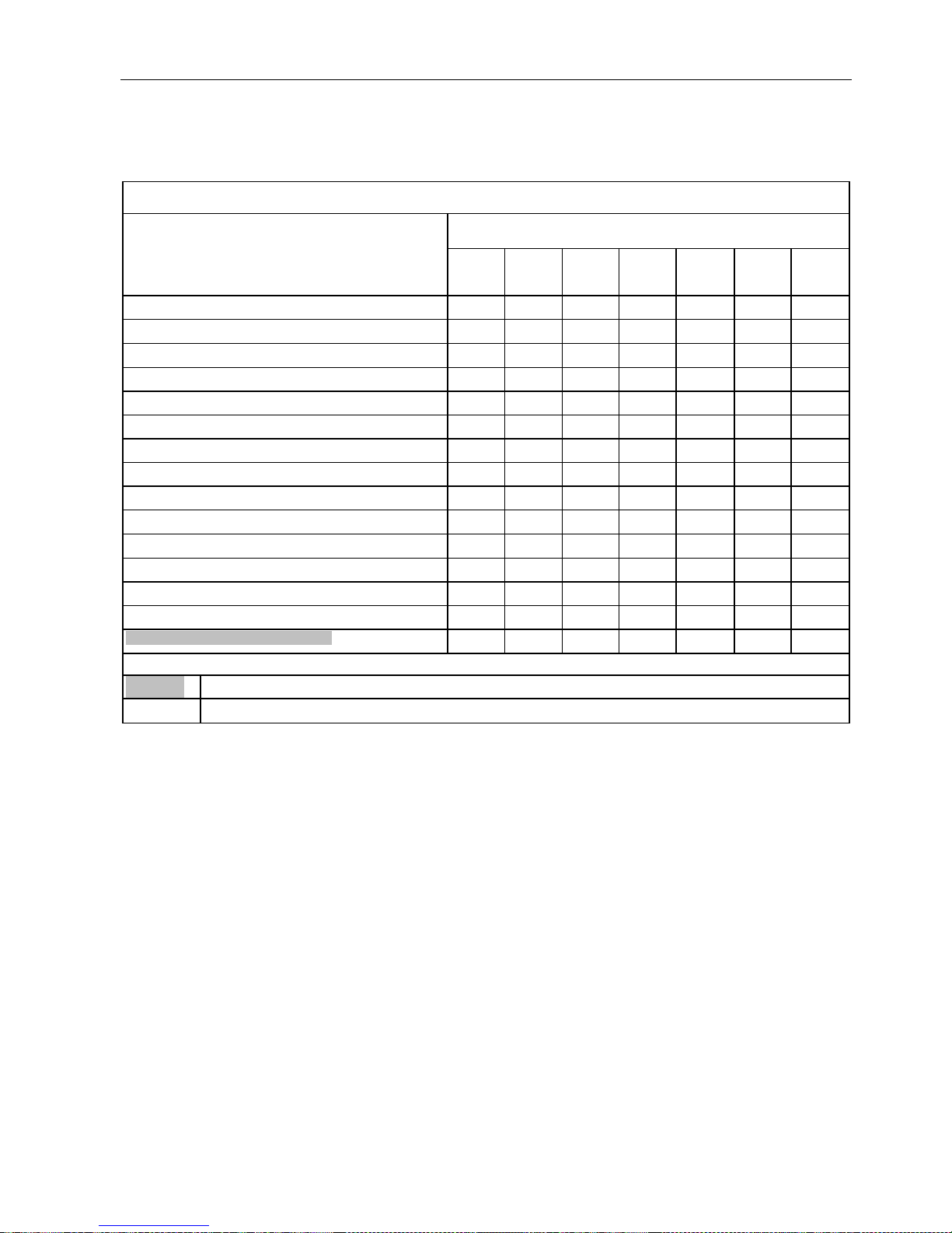
Operation manual - Spider ILD01
36 / 54 rev. 07-01-01-2010
11.2 MAINTENANCE CHART - ENGINE
Engine maintenance chart: Kawasaki FH 500V, FH531V
Maintenance
Period according to t he operating hour s counter
* = Perform more often i n dusty conditions
K =Performed by authorized Kawasaki
service/dealer
Daily
After firs t
8 hours
Every
25 hours
Every
50 hours
Every
100 hours
Every
200 hours
Every
300 hours
Check and add engine oil
Check for loose or lost nuts and screws
Check for fuel and oil leakage
Check or clear air intake screen
* Clean air cleaner foam element
* Clean air cleaner paper element
* Clean dust and dirt from cylinder and cylinder head fins
Tighten nuts and screws
Change engine oil
Clean and set spark plug
Change oil filter
* Replace air cleaner paper element
K Clean combustion chamber
K Check and adjust valve clearance
K Clean and lap valve seating surface
= Device check
= Element replacement
Page 37
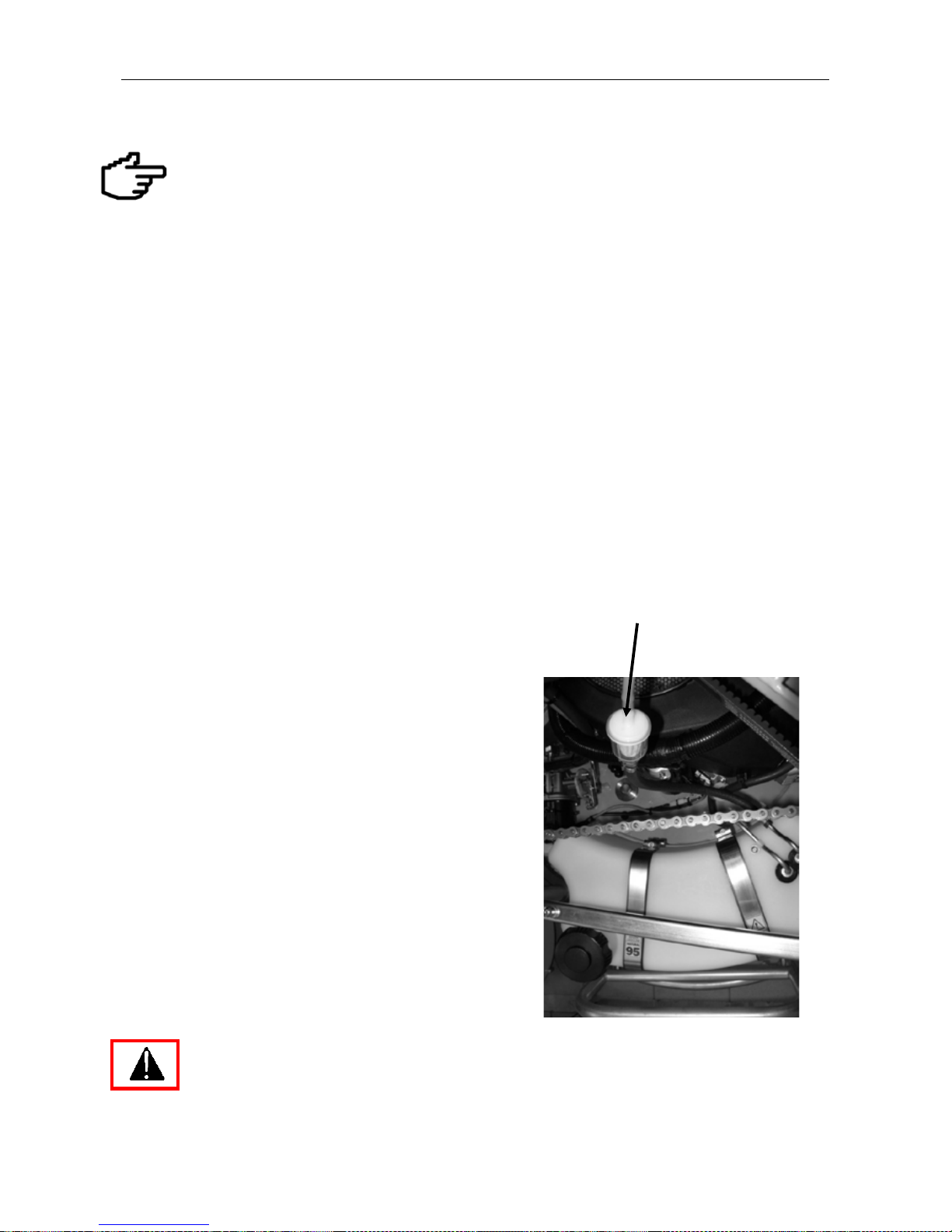
Operation manual - Spider ILD01
37 / 54 rev. 07-01-01-2010
11.3 ENGINE MAINTENANCE
The following activities are considered to
be workshop maintenance and should be
carried out by trained personnel.
.
Before beginning any maintenance activity
on the mower, turn off the engine, p ush the
emergency button and rem ove the key from
the button. Also turn off the remote radio
controller by the switch on the control panel.
To eliminate the pos sibility of an unexpected
start of the mower, disconnect the (+)
terminal connector on the battery.
The engine should only be repaired or
serviced by an authorised dealer/servicing
facility that possesses all necessary tools,
equipment, spare parts and professional
skills.
When maintaining, repairing or cleaning,
always follow the engine manufacturer’s
user’s manual, which is included is the
technical manual pack.
11.4 CLEANING THE FUEL TANK
While using the mower impurities may settle in the fuel
tank. These im purities may caus e a blockage while using
the mower.
The fuel tank may only be emptied by siphoning the
gasoline from the tank, especially if it is full.
The filter hose from the fuel tank leads under the upper part
of the body to the filter. Block ing may be identified by poor
engine performance and by vacuum being created in the
tank.
When working with gasoline do not
smoke or work near open flames.
11.5 MAINTAINING THE HYDRAULIC
Breather filter
Page 38
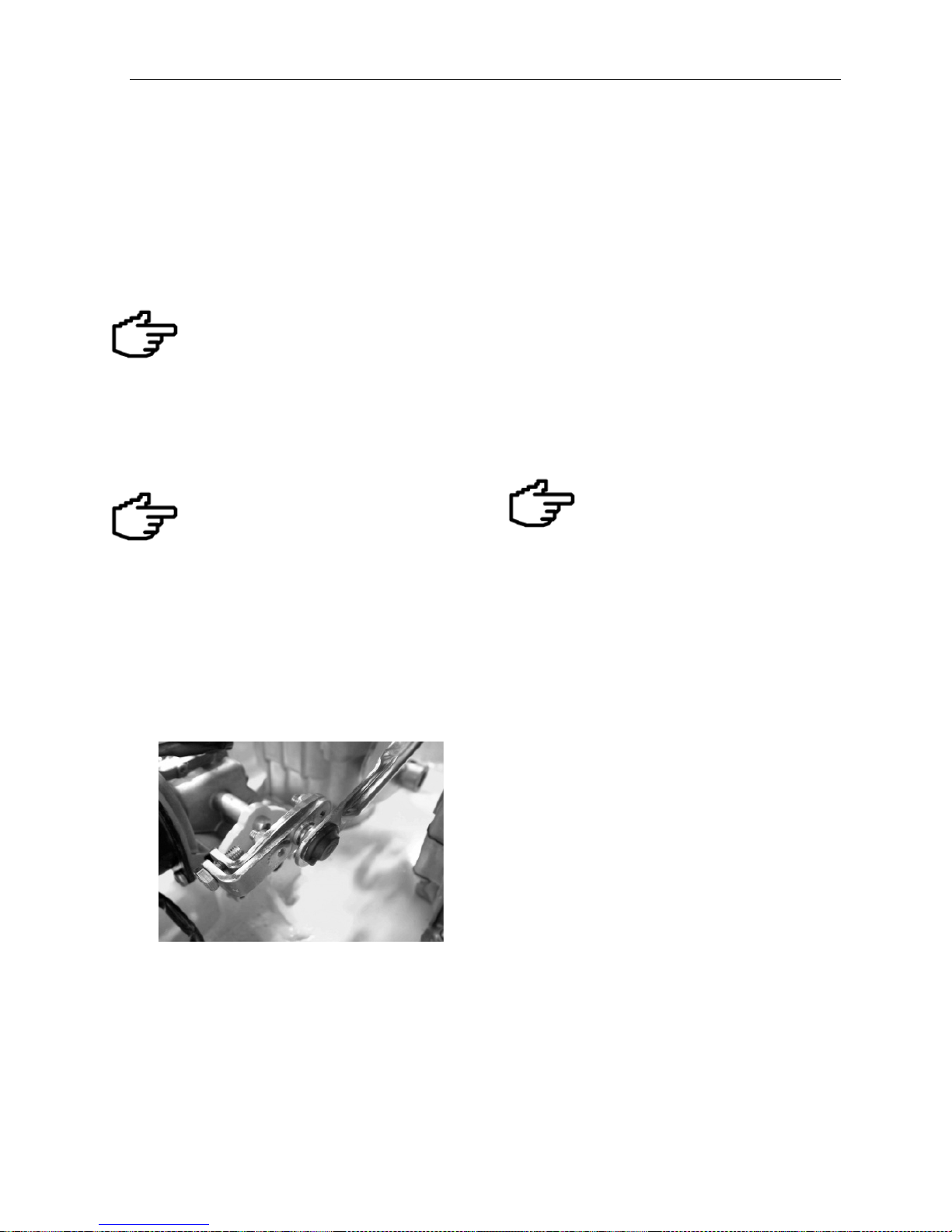
Operation manual - Spider ILD01
38 / 54 rev. 07-01-01-2010
DRIVE
The maintenance of th e hydraulic drive requires
properly trained service personnel.
Regular maintenance s hould address the torqu e
of hydraulic connections and bo lts, replacement
of pressure hoses and oil refilling.
The maintenance of the hydraulic
parts must be carried out in a very
clean working area. An y contam ination
brought into the hydraulic circuit may cause
damage. If replacing any part, remove all
contamination by rinsing it with cleaning fluid.
The hydraulic drive must never work
without or with an insufficient amount
of oil, not even for a short time
11.6 CHECKING AND REFILLING OIL
Check the oil level in the hydraulic oil tank daily.
Measure the oil leve l with the d ipstick in the cap of
the tank. The oil level must be between the limit
marks. If you are working in extreme conditions,
the level of oil (at ambient temperature) must
reach the upper limit mark on the dipstick.
When checking the oil, t he engine mus t be off and
the oil cold.
If you are checking warm or hot oil,
the level of oil may be higher (and
reach above the limit mark) due to
the oil volume expansion.
Do not overfill the hydraulic tank!!!
11.7 ADJUSTMENT OF THE NEUTRAL POSTION OF THE HYDRAULIC DRIVE
This adjustment should only be performed by an authorised service/dealer.
Page 39

Operation manual - Spider ILD01
39 / 54 rev. 07-01-01-2010
11.8 DRIVE V-BELTS
Check the wear and tension of the V-belts and the
tensioning devices.
a) Hydraulic pump drive
Located under the cutter deck inside cover A.
The V-belt is tensioned aut omaticall y by a spr ing
and a tension pulley.
b) Travel wheels drive
The V-belt is tensioned by a tension pulley B.
11.9 GEOMETRY ADJUSTMENT
If you do not possess necessary equipment and
skills, have t his work performed by an authorized
service/dealer.
- Lift the mower (wheels above ground) and
position the wheels into a straight direction.
- Release the steering chain taper lock (figure
91).
- Place a straight l ath to the wheel portal on the
left side and to the tyre dis c on the right side
and adjust the wheels so th at the y are parallel
(figure 92, figure 93).
- Tighten at least 1 screw of the taper lock
(whichever is accessible). Do not turn the
wheels unless you have tightened at least one
screw - this would distort the geometry!
- After tightening one screw you can turn the
wheels.
- Tighter the second screw.
- Check the geometry with a lath.
- Step-by-step turn wheels and tighten both
screws of the taper locks of all wheels until
they are completely tightened (cca 23 Nm).
Picture 91.
Picture 92.
Picture 93.
A
Page 40

Operation manual - Spider ILD01
40 / 54 rev. 07-01-01-2010
11.10 FINAL GEAR DRIVE TO WHEELS
If you do not possess nece ssar y equipm ent and skills,
have this work performed by an authorized
service/dealer.
Remove the cover of t he final gear drive. The cover is
attached by bolts onto the sides. Adjust the chain
tensioner C so the chain is properly tensioned. The
tensioner can be shifted af ter loosening the fastening
screws (see the figure). T o tighten the chain, slightly
unscrew the thrust bolt.
Do not tension the chain excessively. This could
reduce the durability of the chain and the bearing.
Lubricate the chain by spraying it with lubric ati ng oi l.
11.11 MAINTAINING ELECTRIC CIRCUITS
AND DEVICES, TRANSMITTER
Keep all parts of electric cir cuits clean, es pec iall y from
oil products, dust sediments and dry grass.
Replace conductors with damaged insulation. For
replacement use onl y original conductors supplie d by
the manufacturer.
Repairing of electric circ uit should only be
performed by an approved dealer.
11.12 ADJUSTING BLADE
DECELERATION
The electromagnetic clutch is placed under the
clutch cover above the r ota r y blades. T he clutc h was
adjusted by the manufacturer. When engaged the
clutch transmits power onto the blade, when
disengaged the brake stops the rotating blade. Do
not change the clutch sett ing. If damage on th is part
of the machine should occur, always leave the
repairing to an approved dealer. The maximum
rundown time of the rotary blade was set to 5
seconds.
After finishing any work on the electromagnetic clutch, the cover must be returned
to its original place and properly sealed to
prevent the clutch from getting dirty.
11.13 CHAINS
STEERING CHAIN
Check the wear and tension of the chain and the
tensioning devices. The chain can by tightened by
rotating the steering motor bracket after loosening two
attachment bolts (see the figure).
Page 41
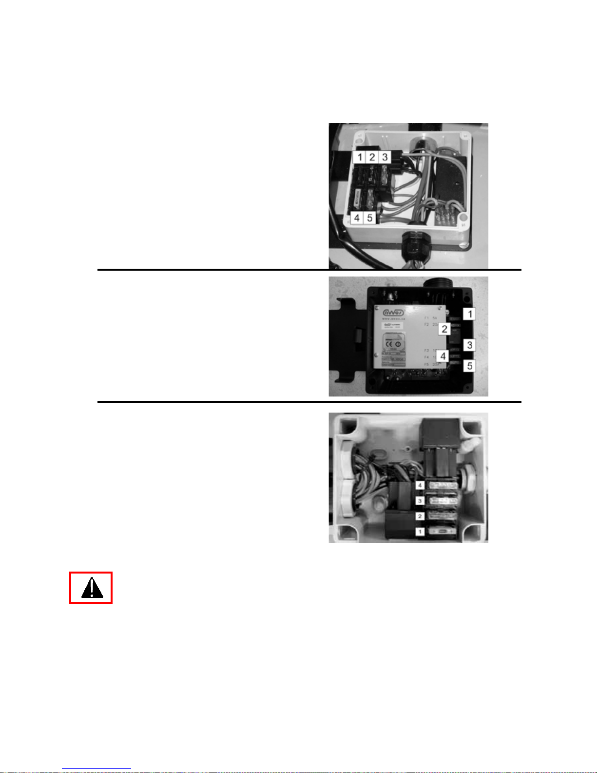
Operation manual - Spider ILD01
41 / 54 rev. 07-01-01-2010
11.14 FUSES
The fuse box is placed in the space next to the
battery. Inside the fuse box you can find fuses for
individual circuits:
1 10 A – Control panel, carburettor solenoid
2 15 A – Control unit, travel control, mower
elevation
3 20 A – Steering servomotor
4 30 A – Main fuse
5 20 A – Battery charging, blade clutch
1 5 A – Control Unit, Accelerator Servo,
Control Panel, Moving Servo
2 20 A – Alternator
3 10 A – Starter, Blade Clutch, Horn
4 10 A – Linear Electric Motors
5 25 A – Steering servo
1. 5 A - Control panel
2. 20 A - Battery charging
3, 4. 2 x 20 A - Parallel protection of the main circuit
When changing fuses follow the electric current
value for which the fuses are designed. Do not
replace damaged fuses with fuses with a higher or
lower electric current value. These could cause
damage or even a fire in the mower!
Page 42
Operation manual - Spider ILD01
42 / 54 rev. 07-01-01-2010
11.15 MOWING BLADE
Check the state of cutting bl ades in regular i ntervals.
Blade:
Must not show signs of damage such as
twisted, bent or deformed parts of blade.
Must be properly attached by the flange in the
middle of blade.
Must be sharp.
The fastening bolts of the flange m ust not be
damaged.
For proper and reliable functioning the blade is
statically balanced by the manufacturer. This
balance must be preserved during the entire
use of the blade
The blade must be statically balanced after
each sharpening
To tighten the blade, use a torque wrench and
a specified tightening torque of 60 Nm.
If the blade is damaged, it is prohibited to:
Straighten them
Heat them
Weld them
Ream them or otherwise change their
construction.
When replacing worn-out parts follow these rules:
The blade may only be sharpened within the
permitted wear limit. Balancing must be
carried out after sharpening.
The blade cannot be repaired.
When changing the blade, use new fastening
bolts if the current ones show signs of
damage. Only high-tensile steel bolts may be
used for this purpose. No other s teel bolts ar e
acceptable.
If the mowing mechanism vibrates when
engaged, do not continue operating the
mower, turn it off and contact your local
dealer.
To tighten bolts use torque liste d in the chart
at the end of this chapter (see 11.21).
Changing the mowing blade
Raise the mowing devi ce to the tran sport positi on.
Stop the engi ne, swi tch off the RC an d push th e
emergency button on the body of the mower.
Disconnect the battery.
Lift one side of the mower until it leans against
the handles on the other side. Always lift the
mower on the exhaust side tilt it against the
hydraulic tank side to prevent oil entering the air
cleaner.
Secure the lifted side against falling by supporting
it.
Use gloves when changing the blades.
Loosen the fastening bolts. Remove the
bolts and the washers. Be careful when
removing the last bolt, the blade m ay fall to
the ground.
After the blade is r e p laced, fasten it by working in
the reversed order.
Always check the bolts when fastening the blade.
After attaching the blades, check their
tightness. Be very careful when engaging
the mowing mechanism for the first time
after replacement. Check for unknown
sounds, vibrations etc.
Always lift the mower on the
exhaust s ide a nd t ilt a gainst the
hydraulic ta nk s ide to prevent o il
entering the ai r cl eaner. B e a ware
of oil spills.
Page 43

Operation manual - Spider ILD01
43 / 54 rev. 07-01-01-2010
11.16 CHANGING THE WHEEL
Change the wheels on a level, firm surface
Turn the wheel so that the tightening nuts are
accessible from the outside
Stop the engine, remove the key from the
ignition
Secure the machine against movement.
Lift the mower and support it under the cutter
deck
Ensure the machine safe & supported before
working on it.
Loosen the wheel nuts, remove the wheel
After repairing it, attach the wheel back in the
reversed order.
Use suitable tools to unscrew the nuts.
To release the wheel f rom the hub,
unscrew only 3 nuts M12, the
remaining three bolts hold the two-
part rim of the wheel.
The two-part rim may be dismounted
(bolts unscrewed) only it the tyres are
deflated.
11.17 TYRE PRESSURE
Keep the specified tyre pressure. Other values may
unfavourably influence the riding characteristics
especially on slopes. You may even loose control of
the machine.
(max. tire pressure - 25 0 k Pa / 2,5 bar / 36 PSI)
11.18 MOWING HEIGHT ADJUSTMENT MECHANISM
Keep the moving parts of the slide way clean,
undamaged and without an excessive clearance
Page 44
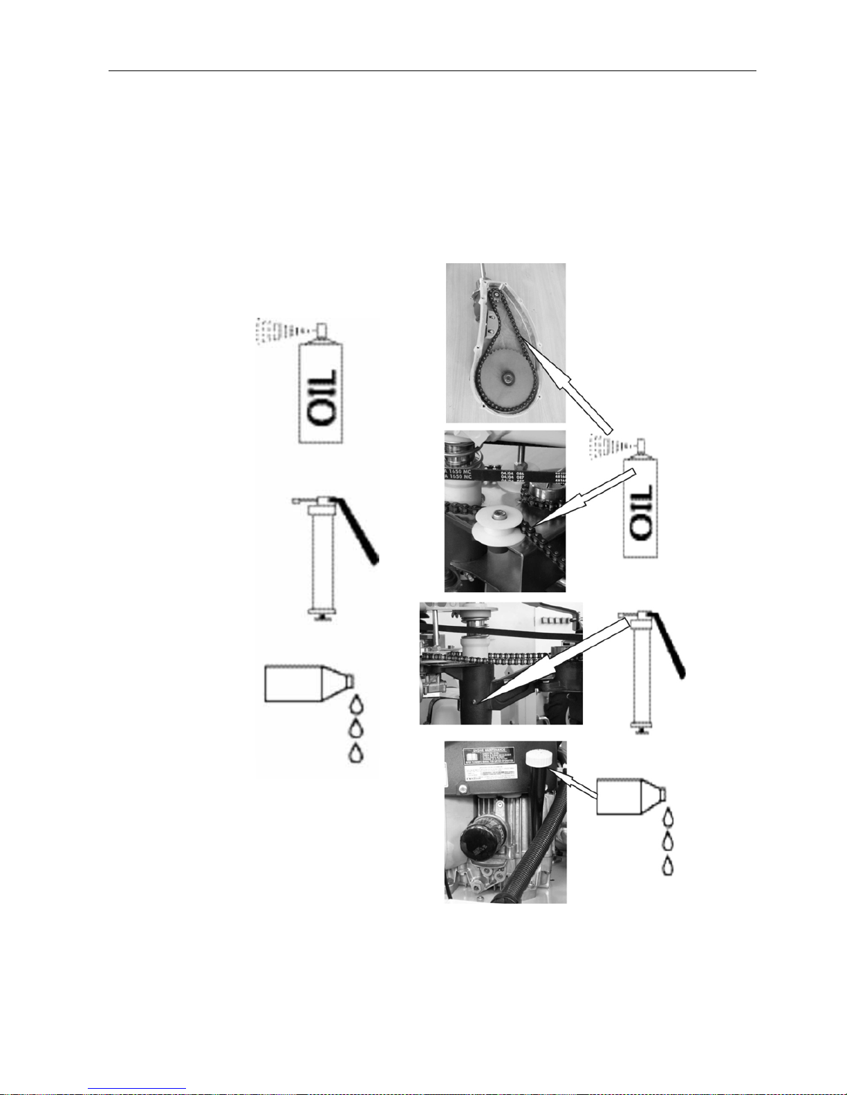
Operation manual - Spider ILD01
44 / 54 rev. 07-01-01-2010
11.19 LUBRICATION
Use adequate amount of lu bricant on parts, which are
to be lubricated. Excessive lubricant tends to drop
down and pollute both the machine and the
environment. Insufficient amount requires frequent
lubrications.
Chain Spray Lubricant:
BERNER , XINTEX - slix
Lubricating grease:
XINTEX – food guard supreme
Motor oil:
Page 45
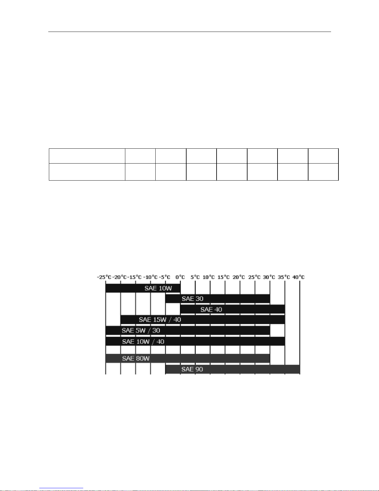
Operation manual - Spider ILD01
45 / 54 rev. 07-01-01-2010
11.20 CLEANING THE MACHINE
Cleaning the whole machine by a power washer or
similar is not recommended. Water under pressure
may penetrate inside electrical parts, carburettor, air
filter and cause malfunction.
Wipe other parts with tissue or brush.
Do not use gasoline or other oil products for cleaning.
11.21 TORQUE CHART
Connection bolt M6 M 8 M 10 M 12 M 14 M 16 M 20
Torque /Nm/
10 25 50 85 135 215 410
11.22 OIL VISCOSITY
Oil requirement may differ according to the use in
different seasons or climatic zones. The following
chart shows the SAE values.
Chart of SAE oil classes according to external temperatures engine / gear
Recommended oils:
SAE 10W – 40 API classification SF or higher
Page 46
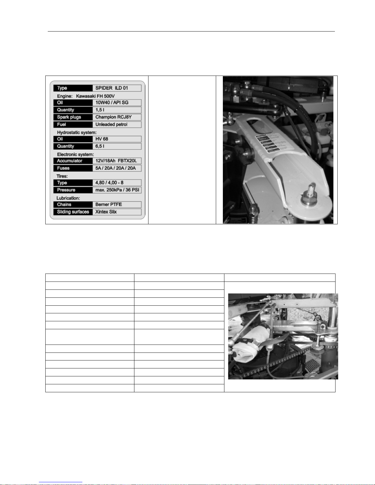
Operation manual - Spider ILD01
46 / 54 rev. 07-01-01-2010
11.23 TECHNICAL PLATE
The technical plate provides information on mower fillings and basic information for machine
maintenance. The technical plate is placed on the machine girder.
- Engine
- Engine oil
- Oil quantity
- Spark plug
- Fuel
- Hydraulic system
- Hydraulic oil
- Oil quantity
- Electronic system
- Battery
- Fuses
- Tires
- Tire ty pe
- Maximal pressure
- Lubrication
- Chain gears
- Sliding surfaces
11.24 TOOLS
Spider ILD01 is equ ipped with a basic set of tools, which allow regular maintenanc e and basic servicing. The
tools are based under the side c o ver upon to the Fuel tank (s ee figure bel o w). T he tool r ol l is also equ ipp ed w ith
a pocked for the business card of your local authorized service/dealer.
List of tools Use Placement on the machine
Spark plug spanner 19, 21 mm Spark plugs
Socket head 19 mm
Change of blades
Socket head 17 mm
Change of wheels
Socket head 15 mm Tightening of drive belts
Lever handle
-
Flat spanner 10-13 mm
Tightening of drive belts
Flat spanner 16-17 mm
By-pass, tightening of steering
chain
Hex-wrench IMBUS 3 mm
Wheel suspension
Hex-wrench IMBUS 5 mm Wheel suspension
Hex-wrench IMBUS 6 mm
Wheel suspension
Hex-wrench IMBUS 8 mm
Tightening of steering chain
Screwdriver flat-tip / crossshead Fuse box
Fuses 5A, 20A
Fuse box
Page 47

Operation manual - Spider ILD01
47 / 54 rev. 07-01-01-2010
12 TROUBLESHOOTING
Problem
Possible cause
Correction
Nothing appears on the display
RC battery is exhausted
R
eplace the batter y with a charged
Engine does not start
Accumulator is discharged
Charge the battery
Accumulator is disconnected
Attach terminal connectors to the
Cable lines are broken
Check/replace the cable lines
Spark plug does not spark
Clean the spark plug
Fuel filter is clogged
Change it
Not enough fuel
Refuel
Not enough oil in engine
Refill oil up to the required level
No signal or the mower is out of the
signal range
Check the aerial attac hment
/ Move
closer to the mower
Emergency button on the mower is
pressed
Unlock the button
The mower does not travel
properly/at all
Not enough oil in the hydraulic
Refill oil and de-aerate properly
Oil is overheated
Clean the fan area, wait till
oil cools down
Hydraulic pump filter is clogged
Change it
Mechanic elements of the
hydraulic drive are worn out
Change them
The mower cannot climb slopes
V-belts are worn
Replace them
V-belts are not tensioned enough
Tension them
Damaged hydraulic pump
servomotor
Change it
The mower vibrates when started
Blade carrier shaft is curved
Replace the shaft
Blade is damaged
Replace the blade
Blade is not attached properly
Change the blade b olts and tighten
Unevenly worn out or damaged
Replace it
Bad mowing quality
Grass is overgrown, too high
Mow only grass which is maximum
3x taller that the pre-
set stubble
height. W e recommend to mow the
Worn/blunt cutting edge of the
Sharpen or replace the blade
Grass is too wet
Wait till the grass dries
Low engine speed
Set the engine speed to maximum
Too high driving speed Lower the driving speed
Page 48

Page 49

Operation manual - Spider ILD01
49 / 54 rev. 07-01-01-2010
13 MAINTENANCE AFTER SEASON
When the season is over or if the machine is not going t o be used for longer than 1
month, it is advisable to prepare it for storage.
If fuel stays in a tank longer than 1 m onth without moving, it ma y create stick y sedim ent
that can unfavourably affect the carburettor and the whole fuel system and cause
engine malfunction.
• Thoroughly clean the whole machine, especially the mowing
mechanism.
• Replace damaged or worn-out parts
• Check all bolted connections. Tighten all loose nuts and screws.
• Lubricate all mobile parts – the whole machine (according to the
lubrication plan)
• Empty the fuel tank and let the engine run until it runs out of fuel.
• When emptying the fuel tank, work in an open area outside.
• Prepar e the engine for storage (accor ding to the user’s manual of the
engine)
• Dis c onnect the ig nit io n cab l e.
• Uns crew th e spark plug and pour a little oi l into the c ylinder bore (abou t
1 cm (0,4inch)).
• T urn the engine by starting it shortly with the ignit ion key without spark
plugs on.
• Screw the spark plug back hand tight. Do not connect the cable.
• Dismount the Accumulator and store it on the dry and warm place
• Kee p the mower on the save and dry place. Use the perm eable cover
to save the mower against the corrosion
Page 50

Operation manual - Spider ILD01
50 / 54 rev. 07-01-01-2010
14 WARRANTY CONDITIONS
This document sets out the extent, conditions and manner of exercising rights stemming from the
Manufacturer’s liability for defects of the delivered Product
1. Dvořák – svahové sekačky Ltd., registered office Dvorce 62, Havlíčkův Brod 58001, Czech Republic,
ID N o. 2 601379 (fu rther referred to a s “ Manufacturer”) p rovides a W arranty fo r n ew P roducts
according to the set regulations for a period of 24 months from the day the Product is delivered to
the C ustomer, o r fr om s uch a P roduct b eing s et i nto o peration, o r u p to 8 00 o perating h ours,
according to w hichever h appens fi rst. T he W arranty p eriod fo r n ew s pare p arts d elivered u nder
Warranty expires together with the Warranty period of the whole Product/machine.
2. Claims s temming f rom t he W arranty m ust b e e xercised w ith th e D istributor / D ealer a nd a lso
resolved b y th em. A p roperly completed W arranty sheet m ust b e p resented a nd a ll o f th e
inspections p rescribed b y th e M anufacturer m ust h ave b een i mplemented. I ncorrect i nformation,
additional extracts or overwriting on the Warranty card lead to loss of the Warranty.
3. The W arranty a pplies to defects o n th e Product c aused b y d efective r aw materials, construction
faults or made workmanship. Defective parts on the Product will be replaced free of charge with a
new part or repaired. No entitlement to immediate delivery is created and the Manufacturer takes on
no liability for damage claimed for as a result of delayed delivery.
4. The Warranty does not relate to regular wear and tear (parts susceptible to regular wear and tear
especially include the following: blades, blade hubs with bearings, bearings of wheel shafts, spark
plugs, air filters, belts, chains, tires, sealing, hydraulic hoses, winch rope etc…).
5. The Warranty cannot be claimed against if the cause of the defect is:
a) The effects of external mechanical or chemical influences on the Product
b) Unreasonable handling of the Product, overloading it, neglect or incorrect operation
c) Repair of maintenance of the Product performed by a third party, which was not authorised to
carry out such work by the Distributor / Dealer or Manufacturer
d) Installation o f s uch p arts i nto th e P roduct, th e u se o f w hich i s n ot a pproved b y th e
Manufacturer
e) Implementation of changes to the Product, which were not approved by the Manufacturer
f) The fact that the Manufacturer’s regulations were not adhered to for handling the Product, its
maintenance a nd t reatment (e -g. th e i nstruction and m aintenance manual), e specially i f th e
prescribed Warranty inspections were not carried out
g) The fact that the user neglected declaration and removal of defects, which were apparent when
they to ok r eceipt o f the P roduct or w hich they d id n ot immediately p rovide n otification o f a n
have removed, when they arose later
6. In c ase o f P roducts s old w ith a d iscount th e W arranty d oes n ot e xtend to d efect fo r w hich th e
discount was granted.
7. All claims stemming from the Warranty are forfeit on expiry of the Warranty period. In the case of
defects, for which notification was made during the course of the Warranty period and which were
not r emoved d uring th is p eriod, th is W arranty remains v alid u ntil th e d efect i s r emoved. In th is
case, the Warranty is terminated at the latest within 1 month of the last repair or after declaration
by the Distributor / Dealer that the defect was removed or that this does not concern a defect.
8. The Manufacturer i s n ot l iable fo r a ny e conomic l oss o r fo r a ny s ubsequent d amage c aused to
persons or their property, which was created as a result of failure of the Product.
9. The Warranty will only be valid subject to the condition that the correctly completed part 2 of the
“Combined delivery note” is delivered to the Manufacturer within 14 days of the date the Product is
delivered to the Customer.
10. The Warranty applies to the Product i n the condition in which it leaves the production p lant. The
Manufacturer is not liable for damage during transportation.
Page 51

Operation manual - Spider ILD01
51 / 54 rev. 07-01-01-2010
11. In th e e vent o f a c hange i n o wner, i t i s p ossible to tr ansfer th e r emaining p art o f th e W arranty
period to the new o wner if the M anufacturer is requested to do so. The new owner confirms that
they h ave ta ken receipt of the instruction m anual a t th e s ame ti me a s the Product as well as the
Warranty conditions and that they agree with these.
12. The Warranty period is extended by the period of the duration of the Warranty claim assessment.
(The Warranty claim assessment period begins on the day following the day the Product is
accepted for assessment and terminates on the day the Warranty is acknowledged or rejected, not
on th e d ay th e Customer co llects t he Product b ack). I n case t he W arranty claim is r ejected, t he
Warranty period will not be extended!
13. After inspecting relevant documents and the claimed product the Distributor / Dealer will:
a) acknowledge the Warranty claim as warrantable and settle the claim on spot; in case it is not
possible to settle the acknowledged claim on spot, they will accept the Product into Warranty
procedure during which the acknowledged claim will be settled without unnecessary delay. The
Distributor / Dealer will issue a written document certifying the acceptance of the Product from
the Customer and both parties will confirm it by their signatures; or
b) reject the Warranty claim as unwarrantable and together with the Customer they will agree on
further steps, or
c) accept the claimed Product for a professional assessment based on which the warranty claim
will either be acknowledged and consequently settled without unnecessary delay, or rejected.
The Distributor / Dealer will issue a written document certifying the acceptance of the Product
from the Customer and both parties will confirm it by their signatures. The Distributor / Dealer
will inform the Customer about the result of the assessment (acknowledgement or rejection of
the W arranty c laim) in a p reviously ag reed m anner (i n w riting o r b y o ne o f l ong-distance
communication devices).
Page 52

Operation manual - Spider ILD01
52 / 54 rev. 07-01-01-2010
15 BILL OF DELIVERY
Combined delivery note
-------------------------------------------------------------------------------------------------
Copy for Dealer (Part 1)
Dealer:
Address:
Tel., Fax, E-mail:
1. DELIVERY NOTE
Date ____ /_____200__ Owner ___________________
Product ____________________ Address _________________________
____________________________
Serial number ________________
Accessories _________________ Tel., fax, E-mail ____________________
____________________________
____________________________ Dealer __________________________
-------------------------------------------------------------------------------------------------
Send to Producer (Part 2)
Dealer:
Address:
Tel., Fax, E-mail:
2. DELIVERY NOTE/ CONFIRMATION BY OWNER THAT THEY HAVE
READ AND UNDERSTOOD THE OPERATING INSTRUCTIONS
Date ____ /_____200__ Owner ___________________
Product ____________________ Address _________________________
____________________________
Serial number ________________
Accessories _________________ Tel., fax, E-mail ____________________
____________________________
____________________________ Dealer __________________________
Confirmation
I have read the instructions for users and the safety instructions set out in
the operating instructions for the Product and understood them.
Owners Signature ______________________________________
Page 53

Page 54

Jacobsen, A Textron Company
11108 Quality Drive, Charlotte,
NC 28273, USA
www.Jacobsen.com
Ransomes Jacobsen Limited
West Road, Ransomes Europark, Ipswich, IP3
9TT
English Company Registr at ion No. 107 073 1
www.ransomesjacobsen.com
 Loading...