

Page 1

GB
United
Kingdom
QUICK START GUIDE
Ransomes MP493 Ride on Rotary Mower with Cab
STARTING THE ENGINE
SEAT ADJUSTMENT
CONTROLS
DRIVING
MOWING
VISUAL DISPLA Y
Refer To The Safety, Operation And Maintenance Manual For Full Operating Instructions.
25108G-GB (rev.0)
RJL 100 July 2015
Page 2

QUICK START GUIDE
en-2
Ransomes Jacobsen Limited reserves the right to make design changes without obligation to
make these changes on units previously sold and the information contained in this manual is
subject to change without notice.
© 2015, Ransomes Jacobsen Limited. All Rights Reserved
Page 3
QUICK START GUIDE
en-3
BEFORE YOU OPERATE FOR THE FIRST
TIME
• Check and adjust tyre pressure, if
necessary, see Safety, Operation and
Maintenance manual.
• If necessary, add diesel fuel to tank.
• Check engine oil and if necessary fill.
• Check the radiator coolant and fill if
necessary (Water with 50% antifreeze).
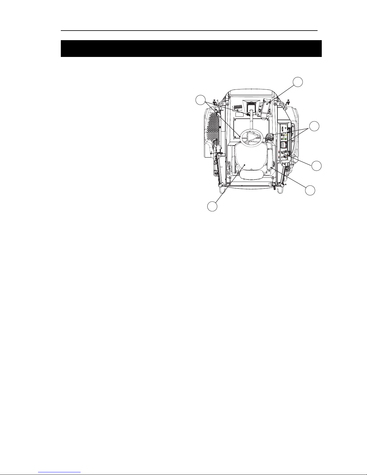
HOW TO START THE ENGINE
The following procedure is for cold engines.
1. Make sure the forward / reverse pedal
(A) is in the neutral position. The cutter
switch (B) is off and the throttle (C) is in
the centre position.
2. Turn the ignition switch (D) to the right
and hold until the engine starts
(approximately 5-10 seconds.)
3. The glow plugs operate automatically.
The time taken for the engine to start,
depends on the temperature of the
coolant
4. When the engine starts, release the key
immediately. The key returns to the
RUN position.
5. If the engine does not start, return the
key to the OFF position and try again.
NOTES
• If the engine does not start after two
tries, wait 20 seconds and try again.
• The starter motor must not be run
continuously for longer than 30 seconds
or the starter motor can fail.
• If the red LED’s on the display flash
when you start one of the safety
interlock switches was not set correctly.
HOW TO STO P T H E ENGINE
1. Disengage drive to the cutting units with
the cutter switch (B).
2. Return the forward / reverse pedal (A) to
the neutral position.
3. Set the parking brake by pressing the
parking brake switch (E).
4. Move the throttle control lever to the
SLOW position.
5. Turn the ignition key (D) to the OFF
position.
STARTING THE ENGINE
5.3
5.8
5.6
5.4
7.11
1234.51234.5
12V
10A
5.2
Page 4
QUICK START GUIDE
en-4
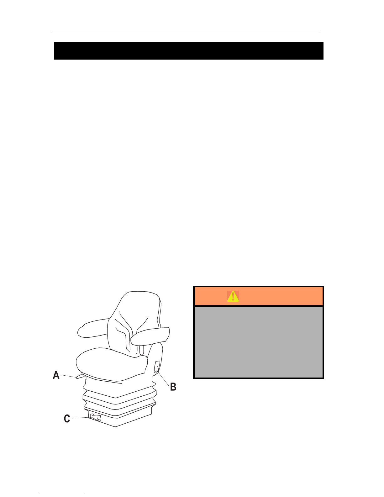
SEAT (GRAMMER MSG85)
Adjustments to the seat can be made for leg
reach, backrest angle and operator weight to
give a good position to operate the machine.
A. FORWARD AND BACKWARD
ADJUSTMENT
To Adjust
The position of the adjusting lever (A) is on
the right hand side of the seat below the seat
cushion. When moved up, the seat may be
moved backward and forward. When, in the
correct position release the lever into one of
the preset positions.
B. BACKREST ADJUSTMENT
To Adjust
The position of the release lever (B) is on the
left hand side of the seat. While, sitting on
the seat pull the release lever up to release
the backrest. (The backrest is spring loaded
to fold forward to the seat Cushion.) Move
back to get the correct position.
Release the lever to engage in one of the
preset positions.
C. WEIGHT ADJUSTMENT
To Adjust
The position of the operator weight adjust
lever (C) is on the front of the seat. To
change the operator weight setting pull the
lever out. When sitting on the seat rotate the
lever until your weight (kg) is shown in the
window.
D.HEIGHT ADJUSTMENT
To adjust
The height of the seat is adjusted by holding
the edge of the seat cushion, pushing your
weight down and lifting. There are three
preset positions. When the highest has been
achieved the seat returns to its lowest
position.
NOTES
The seat is fitted with a microswitch to sense
the operator in the seat.
Wear the seat belt when a ROPS frame or
ROPS cab are installed.
WARNING
Operator weight adju st men t
must be set to ensure the OPC
operates correctly. The parking
brake may automatically be
applied if this operation is not
carried out correctly.
SEAT ADJUSTMENT
Page 5
QUICK START GUIDE
en-5
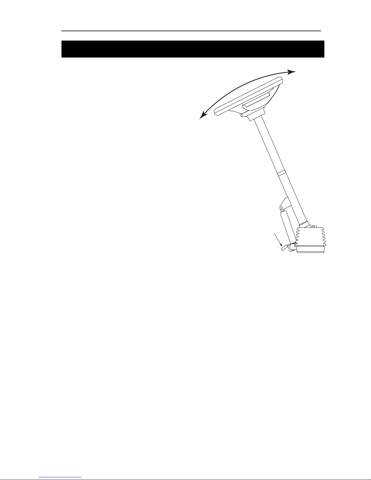
STEERING TILT CONTROL
When the operators seat is in the correct
position to operate the traction pedal
comfortably. Push the small foot pedal (A) at
the base of the steering column. Tilt the
column backward or forward to the correct
position. Release the small foot pedal to lock
the steering column in position.
STEERING WHEEL ADJUSTMENT
A
Page 6
QUICK START GUIDE
en-6
CONTROLS
R
S
L
T
J
A
E
F
B
V
C
H
6.6
6.5
P
N
K
D
W
1234.5
12V
10
A
G
1234.5
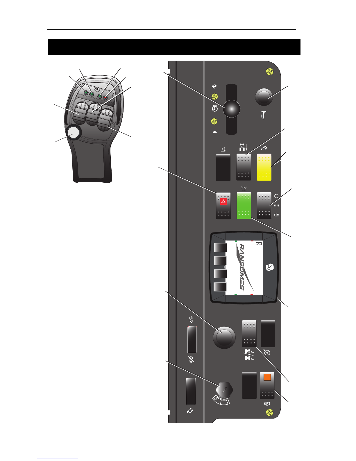
A: Starter Key Switch
B: Throttle Control Lever
C: Parking Brake Switch
D. Hazard Warning Switch
E: Cutter Switch
F. Beacon (Optional)
G: 4 WD Reverse
H: Visual Display
J. Right Side Unit Lift and
Lower Switch
K. Centre Unit Lift and
Lower Switch
L. Left Side Unit Lift and
Lower Switch
N LED - Cutting Unit is
engaged
P LED - Right side cutting
unit in cutting position.
R LED - Centre cutting
unit in cutting position.
S LED - Left side cutting
unit in cutting position
T Weight Transfer Button
V Auxiliary Hydraulic
System Kit Switch
(Optional)
W. Light Switch (Optional)
Page 7
QUICK START GUIDE
en-7
CONTROLS
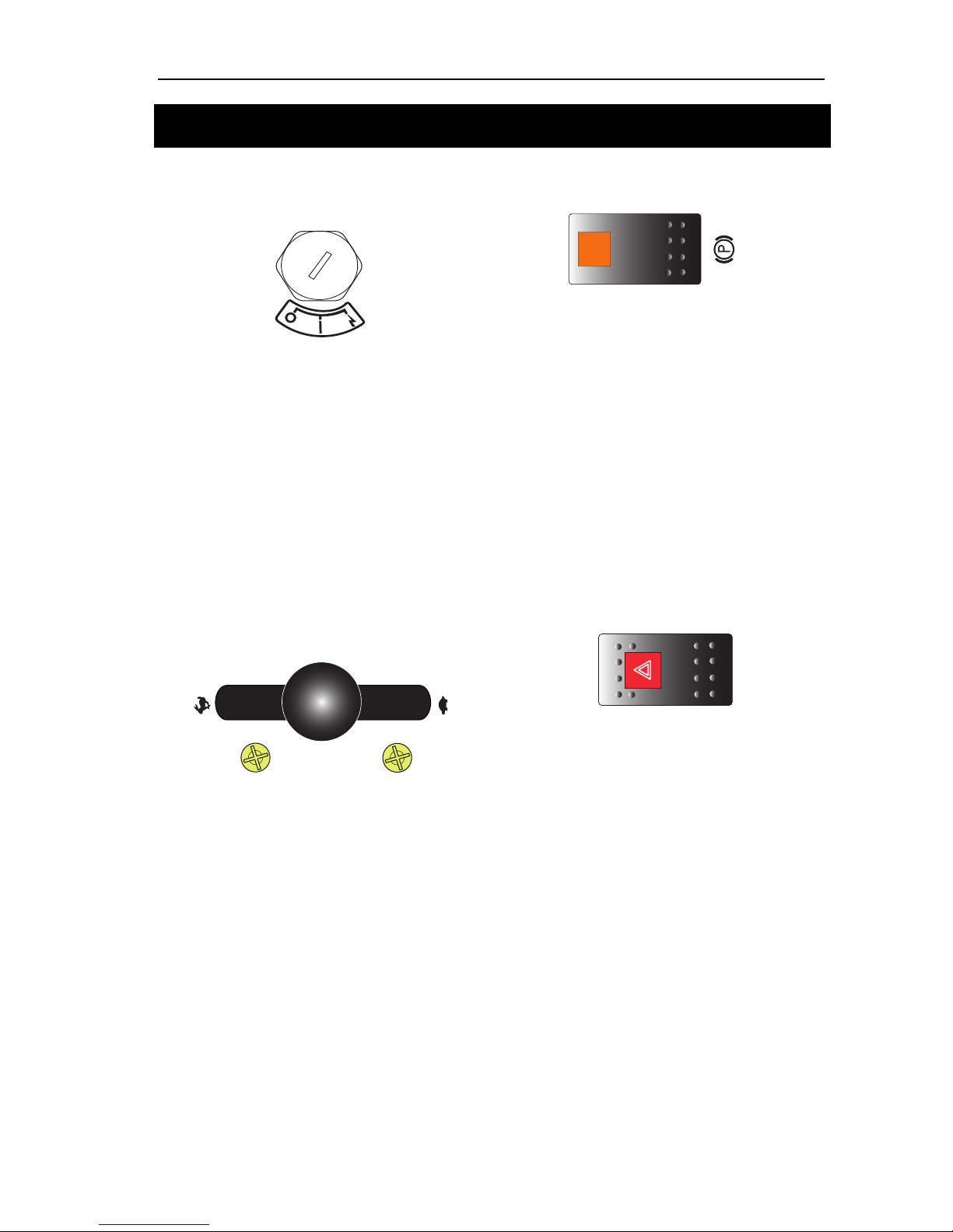
STARTER KEY SWITCH
Turn the starter key to the right to start the
engine. Release the key to return
automatically to the 'on' position for normal
operation.
NOTE: Before the engine starts, the glow
plugs automatically preheat. The visual
display shows the glow plug symbol and
counter to indicate that the automatic
preheat is in operation.
THROTTLE CONTROL LEVER
The lever is moved away from the operator
to increase the engine speed and toward the
operator to decrease the engine speed.
NOTE: The engine must always be used at
full speed
PARKING BRAKE SWITCH
When the engine is running the Parking
brake is applied by sliding back the orange
button on the rocker and depressing the
switch on the control panel. When the engi ne
is switched off the parking brake is
automatically applied.
To release the parking brake depress the
opposite end of the rocker switch.
DO NOT apply the brake when the machine
is moving
HAZARD WARNING SWITCH
Switches the hazard warning indicators on
and off. The red lens flashes when switched
on.
Page 8
QUICK START GUIDE
en-8
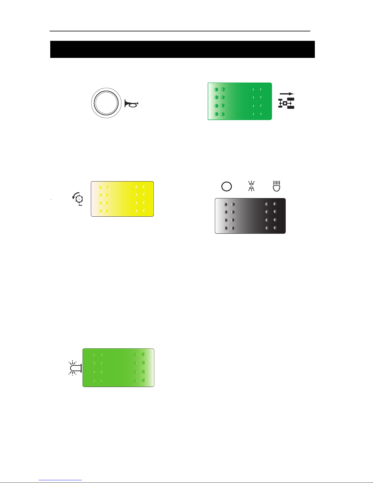
HORN BUTTON
For machines without the lighting kit.
The horn button (A) is on the control panel. If
the lighting kit is fitted, the horn is found on
the end of the indicator stalk.
CUTTER SWITC H
To start to cut make sure the speed limiter is
in mow position and the units are lowered.
To start to cut make sure the speed limiter is
in mow position and the units are lowered.
Push the bottom of the rocker switch and
move joystick toward the lower position.
To stop cutter unit rotation push top of rocker
switch.
Cutting units stop rotating automatically
when raised or the operator leaves the seat.
BEACON SWITCH
Operates the vehicles rotating beacon
4 WHEEL DRIVE IN REVERSE SWITCH
Engages the four wheel drive while the
vehicle is in reverse. The switch must be
held to engage.
LIGHT SWITCH (OPTIONAL)
Allows manual operation of the road lights.
Position 1. OFF
Position 2. Side / Marker Lights
Position 3. Main Beam.
Note
Position 3 - Will not activate with the ignition
turned OFF.
CONTROLS
Page 9
QUICK START GUIDE
en-9
CONTROLS
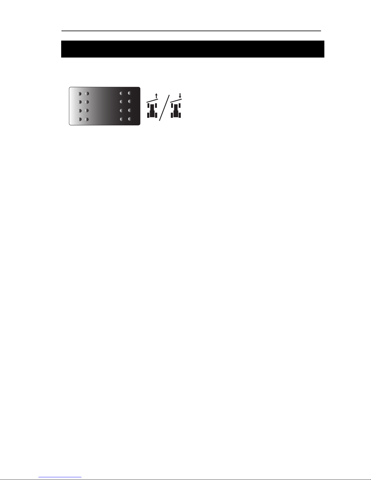
AUXILLARY HYDRAULIC SERVICES KIT
SWITCH (OPTIONAL)
This s w itch set s th e rotary brush or snow
blade to a right side or a left side forward
position.
Push the top of the rocker switch to set a
right side forward position.
Push the bottom of the rocker switch to set a
left side forward position.
1. Release brake - Make sure the parking
brake is released before you try to go
forward or reverse.
2. Forward - Carefully push the top (A) of
the forward/reverse foot pedal to reach
correct ground speed.
3. Reverse - Carefully push the bottom (B)
of the forward/reverse foot pedal to
reach correct ground speed.
4. To stop - Carefully return the forward/
reverse foot pedal to the neutral
position.
5. To hold the vehicle stopped on a slope
it can be necessary to apply an amount
of forward or reverse traction.
NOTE:
• Use complete foot to operate both
forward and reverse.
• Do not move the pedal suddenly,
always operate slowly and carefully. Do
Not move the pedal with force from
forward to reverse or reverse to
forward.
Page 10

QUICK START GUIDE
en-10
HOW TO DRIVE
• Set the throttle to maximum engine
speed.
• Release the parking brake before you
move in a forward or reverse direction.
• Forward - Carefully press the top of the
Traction pedal to engage forward drive.
• Reverse - Carefully press the bottom of
the Traction pedal to engage reverse
drive.
• To stop - Carefully return the Traction
pedal to the Neutral position.
• To stop the vehicle on a slope, it can be
necessary to apply the reverse traction.
NOTE
• Use complete foot to operate both forward and reverse.
• Always operate the traction pedal carefully. Do not move the pedal from
forward to reverse quickly.
DRIVING
Page 11

QUICK START GUIDE
en-11
HOW TO MOW
1. Make sure that the speed limiter is set in
the mow position
2. Release any transport locks and lower
the cutting units with the joysticks.
3. To engage the cutting mechanism,
press the upper half of the cutting unit
switch, found on the control panel.
4. Release the parking brake and drive in
a forward direction.
4. Set a speed compatible with the surface
and gradient you are cutting. When you
operate at speed, danger is increased
and the quality of cut will be
compromised.
When the optional Stability Warning
System is installed
When the mower is driven on a slope of more
than its safe limit, a warning is shown on the
visual display unit. At 22degrees the centre
and upper unit is lifted 4-6 inches above the
ground and all units stop. This makes the
machine stable. This condition continues
until the mower is moved to a safer area.
NOTE
Always set the throttle to the maximum engine speed. If you find wet or thick grass
difficult to cut, decrease the forward speed to increase hydraulic pressure to the
cutting motor s .
NOTE
Always set the throttle to maximum engine speed to cut the grass. When the grass
is heavy or the engine is under stress, decrease forward speed on the forward/
reverse foot pedal.
MOWING
Page 12
QUICK START GUIDE
en-12
The display is activated when the ignition is
turned on.
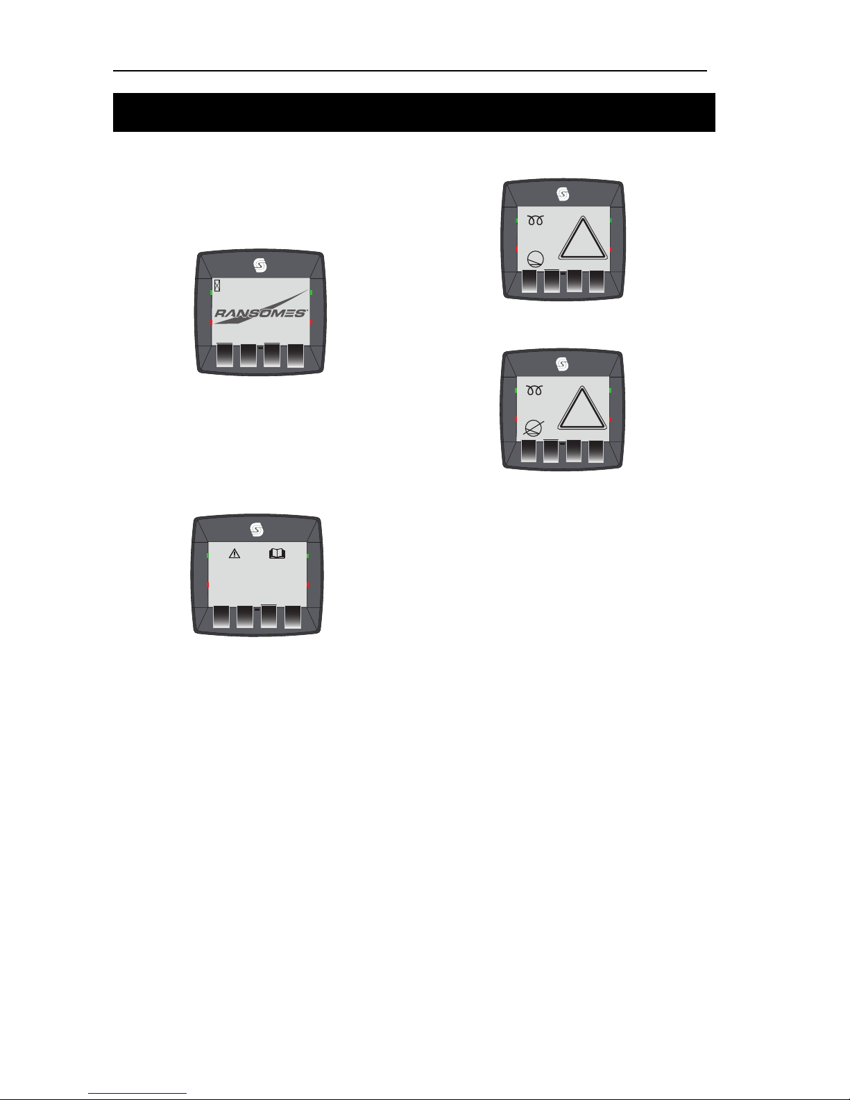
START UP SCREEN
When first turned on,this screen is shown.
The hour meter shows total engine hours.
WARNING/SERVICE SCREEN
After the start up screen, the warning screen
is shown.
If the machine is within 5 hours of the next
service interval, a warning is shown. An
operator input is needed to continue to the
main screen for operation. Otherwise the
main run screen appears. If a fault condition
has occurred during the previous start, a pop
up screen over the top of the warning screen
shows the fault. The operator must confirm
the fault, to continue to the main screen.
START UP SLOPE WARNING SCREEN
When the ignition switch is turned to crank
one of the following screens will be shown.
If the machine is fitted with the slope
monitoring system the screen will display the
logo “TST™” (Tilt Sensor Technology) and
maximum working slope symbol. On the left
hand side of the screen the glow plug symbol
and a count down will be shown to indicate
the time left before the engine will
automatically crank.
If the machine is not fitted with the slope
monitoring system TST™ the screen will
display the logo crossed out and maximum
working slope symbol. On the left hand side
of the screen the glow plug symbol and a
count down will be shown to indicate the time
left before the engine will automatically
crank.
1234.5
WARNING
If incorrectly used this machine can cause
severe injury. Those who use and maintain
this machine should be trained in its proper
use, warned of its dangers and should read
the entire operators manual before attempting
to set up, operate, adjust or service the
machine.
VISUAL DISPLAY
18°
MAX
15°
MAX
5
5
TST
TST
Page 13
QUICK START GUIDE
en-13
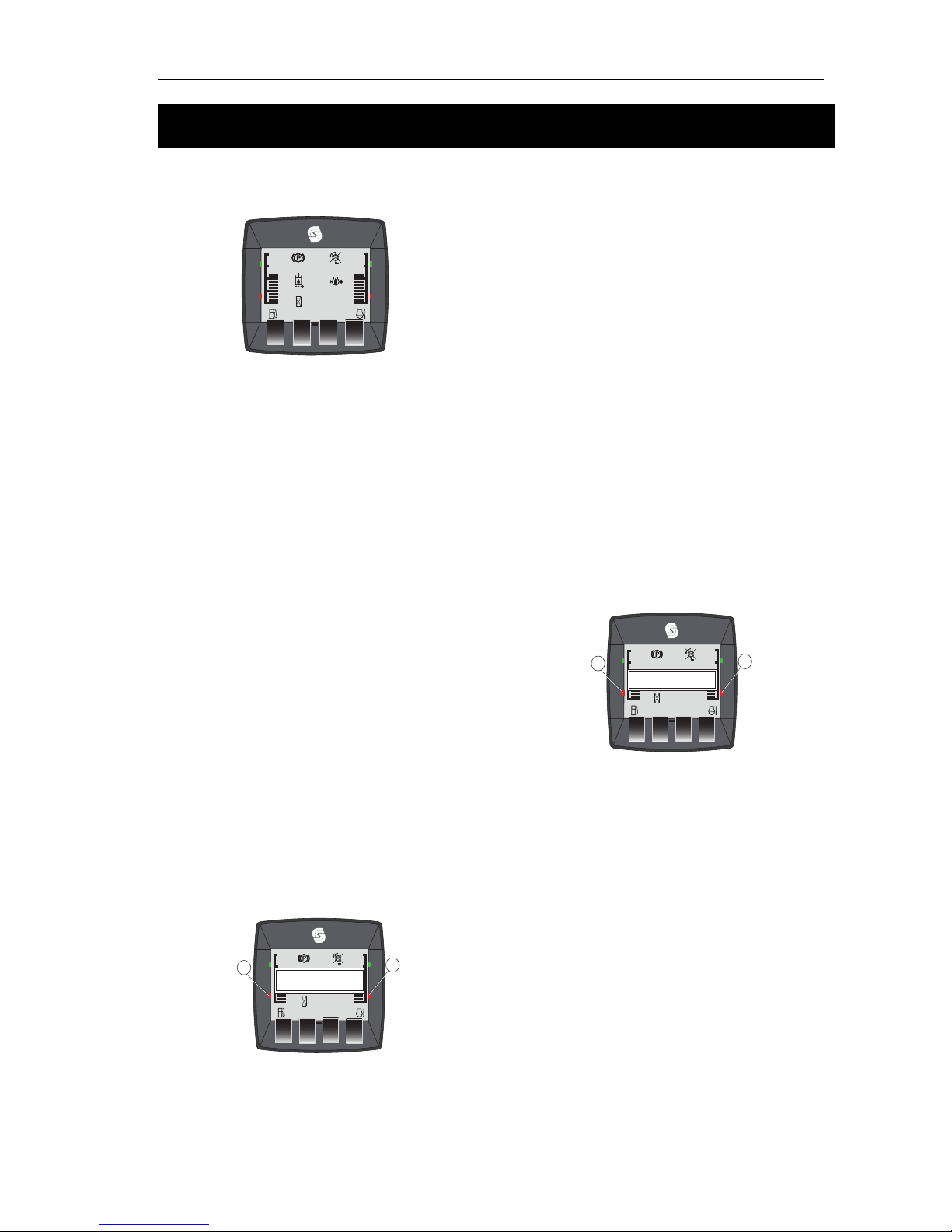
MAIN RUN SCREEN
The main screen for operation gives the
operator all the information necessary to
operate the machine. No operator input to
view standard data is needed when you use
the mower.
If an error occurs when the operator has
moved away from this screen, it immediately
returns to this screen.
When a button is pressed, a bar is shown at
the bottom of the screen to give more
options.
Buttons numbered left to right.
Button 1: Screen Brightness and Contrast
Button 2: Up Arrow (Changes time, from
hour meter to time of day)
Button 3: Down Arrow (Changes time, from
time of day to hour meter)
Button 4: Enters the Menu structure.
If there are no more buttons pressed, the
button bar disappears.
WATER TEMPERATURE SCREEN
If the temperature increases to 108°C, the
RED LEDs (A) will flash at a rate of two
flashes every four seconds. The warning
buzzer will sound at the same rate and the
“CLEAR BUGSCREEN” warning replaces
the centre icons and flashes. Press the
button under the check mark to remove
warning. The RED LED’s will flash and the
buzzer continues until the temperature has
decreased to under 108°C. When the
temperature reaches 110°C, the lift / lower
function is stopped and the power take off is
disengaged. The engine will shutdown at
115°C.
This occurrence will also be recorded to
memory, the data recorded is:
Water Temperature limit reached, Date,
Time, Engine Hours, time above 110°C.
Maximum temperature reached during the
fault.
BLOCKED CHARGE FILTER SCREEN
This situation does not cause a fault until the
hydraulic oil is at operating temperature. If
the charge filter is blocked the icon will be
shown, and the RED LED’s (A) will flash at a
rate of a 1s flash every 5 seconds. The
buzzer will sound at the same rate one
second every 5 seconds.
The fault will also be recorded to memory,
the data recorded is:
Blocked Charge Filter, Date, Time, Engine
Hours, length of time engine continued to run
after the fault occurred.
1234.5
1234.5
HIGH ENGINE TEMPERATURE
A
A
1234.5
BLOCKED CHARGE FILTER
FAULT
A
A
VISUAL DISPLAY
Page 14
QUICK START GUIDE
en-14
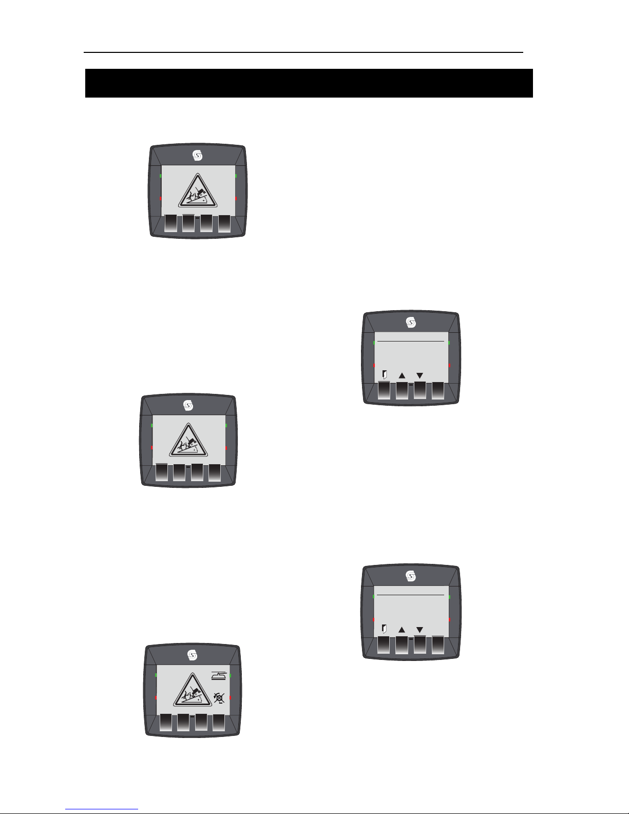
SLOPE WARNING SCREENS
NOTE
The slope warning screens will only become
visible when the TST is installed.
During work, if the machine is driven onto a
slope of more than 16º the screen will display
this warning which over rides all other
information, and will continue until the
machine has been driven to an area of less
than 16º.
If the slope angle reaches 18º, the screen
will display this warning that indicates that
the cutting unit arms are locked in the lower
position. An audible warning will be given,
the buzzer will sound four times every four
seconds and the red LED’s will flash four
times every four seconds. This will continue
until the machine has been driven to an area
of less than 16º.
If the slope angle reaches 22º the screen will
display this warning that indicates that at
22deg the centre and upper unit will be
raised 4"- 6” above the ground to improve
stability and all units stop rotating. An
audible warning will also be given, the
buzzer will sound four times every four
seconds and the red LED’s will flash four
times every four seconds. This continues
until the machine has been driven to an area
of less than 16º.
MAIN MENU
The check mark is moved up and down
using buttons two and three, button four then
enters the selected page. Button one returns
to the main menu. There will be three options
within this menu.
Clock, Service and Language.
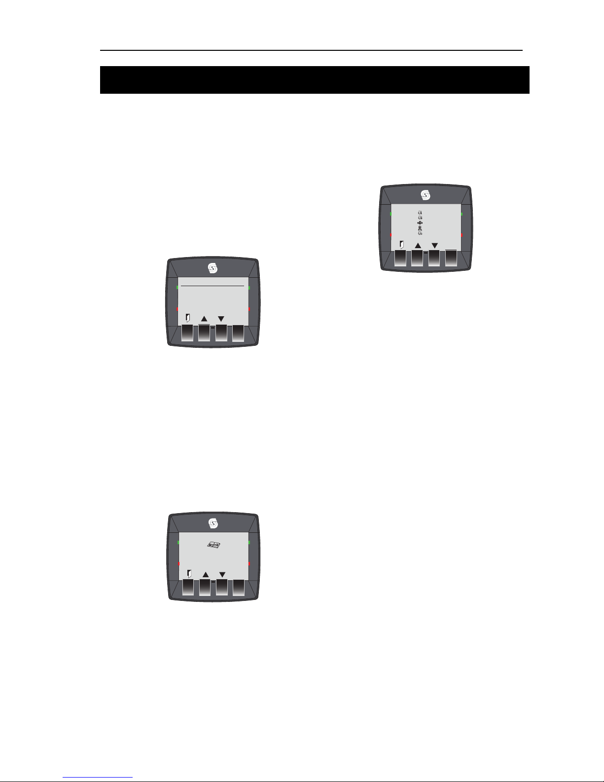
CLOCK AND DATE ADJUST
The Check mark can be moved up and down
to select the date or time. When you press
button four (check mark) a line appears
under the unit to be adjusted. The arrows will
adjust that unit, by 1 unit per press, unless
15
16°
15
18°
15
22°
Main Menu
CLOCK
SERVICE
LANGUAGE
Clock Settings
DATE - 21/06/2008
TIME - 16:08
VISUAL DISPLAY
Page 15
QUICK START GUIDE
en-15
the button is held. If held for one second the
unit increases at a rate of three units per
second. Pressing the check mark will move
the line to the next unit to be adjusted. If at
the end it will move to the time or date.
Pressing button one (exit) will, if no unit is
selected return to the previous menu or if a
unit is selected return to start of this page.
SERVICE MENU
The check mark can be moved up and down
using buttons two and three. Button four then
enters the selected page. Button one returns
to the main menu. There are three options
within this menu.
Fault Log
Time to Service
Diagnostics
A service engineer can reset the time to
service.
The part numbers for service items are
stored within the memory, only numerical
digits are stored.
The first service is at 50 hours, after the first
service the interval is 250 hours.
DATA LOGGING MENU
The last 50 “Faults” that the controller finds
are recorded. When 50 faults are recorded,
the next fault that occurs will overwrite the
oldest fault.
This information is retrieved using the
service tool, or can be seen on the errors
page of the service menu. The same method
of navigating pages applies, the errors scroll
with the last error always at the top of the
screen.
The fault / data record function has three
actions. Each record can contain a
maximum of 50 faults. These are as follows
Inclinometer records the slopes greater than
22°.
Engine records the engine shutdowns
caused by overheat or loss of oil pressure.
Service records hydraulic by-pass and
missed service intervals.
Service Menu
FAULT LOG
TIME TO SERVICE
Diagnostics
Service required in 10 Hours
Parts required for routine service
1234 Fuel Filter
1235 Air Filter
1236 Engine Oil Filter
1237 Hydraulic Filter
12/05/2008
13/05/2008
18/05/2008
22/06/2008
22/06/2008
VISUAL DISPLAY
Page 16
QUICK START GUIDE
en-16
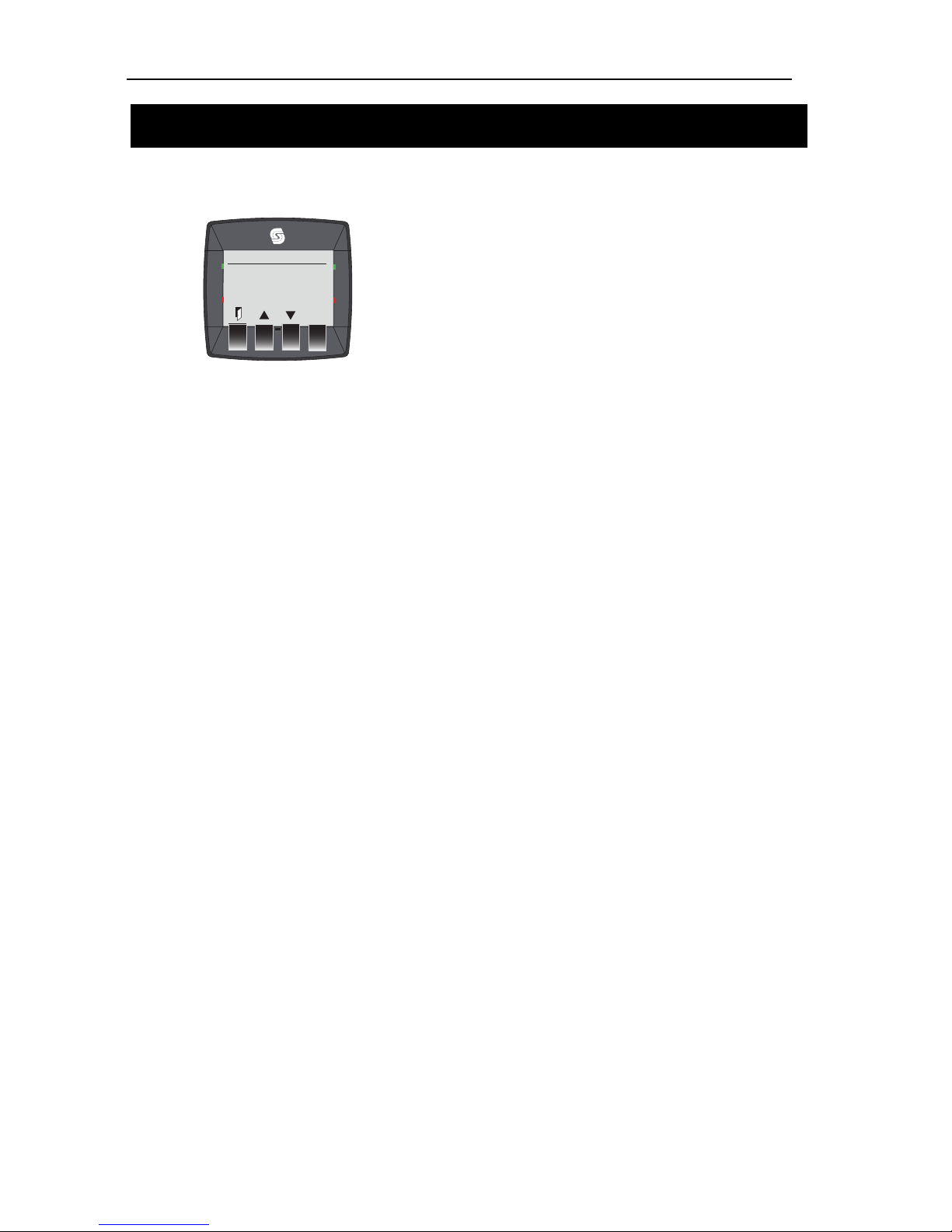
LANGUAGE MENU
When you access the language selection
page, the check mark appears next to the
selected language. When the check mark is
moved up and down, the language does not
change until button four is used to select and
store the language. At that point the title bar
changes to the new selected language.
The options will always be in the correct
language. English, Deutsch, Francaise,
Danish, Swedish and Dutch.
Language Menu
English
Deutsch
Francais
Danish
Swedish
Dutch
VISUAL DISPLAY
Page 17

Page 18

Page 19

Page 20
Europe & Rest of The World Except North & South America
Ransomes Jacobsen Limited
West Road, Ransomes Europark, Ipswich, IP3 9TT
English Company Registration No. 1070731
www.ransomesjacobsen.com
North & South America
Jacobsen, A Textron Company
11108 Quality Drive, Charlotte,
NC 28273, USA
www.Jacobsen.com
 Loading...