

Page 1

Setup, Parts and Maintenance Manual
EC Hydro Midsize
Power Unit Models:
930325A EC Power Unit 15HP Kawasaki Hydro
(Safety & Operation Manual 4122451)
4122450-GB (rev .A)
WARNING: If incorrectly used this machine can cause severe
injury. Those who use and maintain this machine should be
trained in its proper use, warned of its dangers and should
read the entire manual before attempting to set up, operate,
adjust or service the machine.
RJ 100 / 092003
Page 2

© 2002, Ransomes Jacobsen Limited. All Rights Reserved
Page 3

EC
CONTENTS
Hydro
Midsize
IMPORTANT MESSAGE
Thank you for purchasing this Ransomes product. You have purchased a world class mowing product, one of the
best designed and built anywhere.
This machine comes with an Operation and Safety Manual and a separate Setup, Parts and Maintenance Manual.
The useful life and good service you receive from this machine depends to a large extent on how well you read
and understand these manuals. Treat your machine properly, lubricate and adjust it as instructed, and it will give
you many years of reliable service.
Your safe use of this Ransomes product is one of our prime design objectives. Many safety features are built in,
but we also rely on your good sense and care to achieve accident-free operation. For best protection, study the
manuals thoroughly. Learn the proper operation of all controls. Observe all safety precautions. Follow all
instructions and warnings completely. Do not remove or defeat any safety features. Make sure those who operate
this machine are as well informed and careful in its use as you are.
See a Ransomes dealer for any service or parts needed. Ransomes service ensures that you continue to receive
the best results possible from Ransomes’ products. You can trust Ransomes replacement parts because they
are manufactured with the same high precision and quality as the original parts.
Ransomes designs and builds its equipment to serve many years in a safe and productive manner. For longest
life, use this machine only as directed in the manuals, keep it in good repair and follow safety warnings and
instructions. You'll always be glad you did.
T extron Golf, T urf & S pecialty Products
Ransomes Way
Ipswich, England, IP3 9QG
T ABLE OF CONTENTS FIGURES PAGE
SAFETY ......................................................................................................................................................... 2
ASSEMBLY/SET-UP INSTRUCTIONS...................................................................................................... 3-12
LUBRICATION ....................................................................................................................................... 13, 14
MAINTENANCE ...................................................................................................................................... 15-17
SERVICE CHART ........................................................................................................................................ 18
SERVICE RECORD ..................................................................................................................................... 19
ADJUSTMENTS...................................................................................................................................... 20-23
BEL T REPLACEMENT................................................................................................................................. 24
PARTS SECTION......................................................................................................................................... 25
UPPER ENGINE DECK ASSY ........................... FIGURE 1.................................................................. 26, 27
LOWER ENGINE DECK ASSY/CLUTCH........... FIGURE 2.................................................................. 28, 29
DRIVE WHEELS ................................................ FIGURE 3.................................................................. 30, 31
P ARKING BRAKE .............................................. FIGURE 4.................................................................. 32, 33
ELECTRIC ST ART UPPER HANDLE................. FIGURE 5.................................................................. 34, 35
TRACTION CONTROLS .................................... FIGURE 6.................................................................. 36, 37
ELECTRIC START BATTERY............................ FIGURE 7.................................................................. 38, 39
HYDRAULICS .................................................... FIGURE 8.................................................................. 40, 41
DECALS ............................................................. FIGURE 9.................................................................. 42, 43
HYROGEAR PUMP............................................ FIGURE 10................................................................ 44, 45
CUTTERDECK MOUNTING .............................. FIGURE 11................................................................ 46, 47
ELECTRICAL DIAGRAM.................................... FIGURE 12................................................................ 48, 49
ELECTRICAL SCHEMATIC ................................ FIGURE 13...................................................................... 50
11-2001-TGTSP
GB-1
Page 4

SAFETY
EC
Hydro
Midsize
NOTICE !!!
Unauthorized modifications may present extreme
safety hazards to operators and bystanders and
could also result in product damage.
Textron Golf, Turf & Specialty Products strongly
warns against, rejects and disclaims any modifications, add-on accessories or product alterations that
are not designed, developed, tested and approved
by Textron Golf, Turf & Specialty Products Engineering Department. Any Textron Golf, Turf & Specialty
Products product that is altered, modified or changed
in any manner not specifically authorized after original manufacture–including the addition of “aftermarket” accessories or component parts not specifically approved by Textron Golf, Turf & Specialty
Products–will result in the Textron Golf, Turf & Specialty Products Warranty being voided.
Any and all liability for personal injury and/or property
damage caused by any unauthorized modifications,
add-on accessories or products not approved by
Textron Golf, Turf & Specialty Products will be considered the responsibility of the individual(s) or company designing and/or making such changes. Textron
Golf, Turf & Specialty Products will vigorously pursue
full indemnification and costs from any party responsible for such unauthorized post-manufacture modifications and/or accessories should personal injury
and/or property damage result.
This symbol means:
ATTENTION!
BECOME ALERT!
Your safety and the safety of others is involved.
Signal word definitions:
The signal words below are used to identify levels of
hazard seriousness. These words appear in this
manual and on the safety labels attached to Textron
Golf, Turf & Specialty Products machines. For your
safety and the safety of others, read and follow the
information given with these signal words and/or the
symbol shown above.
DANGER indicates an imminently hazardous
situation which, if not avoided, WILL result in death
or serious injury.
WARNING indicates a potentially hazardous situation
which, if not avoided, COULD result in death or
serious injury.
CAUTION indicates a potentially hazardous situation
which, if not avoided, MAY result in minor or moderate
injury. It may also be used to alert against unsafe
practices or property damage.
GB-2
CAUTION used without the safety alert symbol
indicates a potentially hazardous situation which, if
not avoided, MAY result in property damage
MODEL NUMBER: This number appears on
sales literature, technical manuals and price lists.
SERIAL NUMBER: This number appears only
on your mower. It contains the model number
followed consecutively by the serial number. Use
this number when ordering parts or seeking
warranty information.
SERIAL TAG
Page 5

EC
ASSEMBLY/SET-UP INSTRUCTIONS
Hydro
Midsize
GENERAL NOTE: FRONT, REAR, RIGHT HAND AND LEFT HAND REFERENCES BELOW
ARE WITH RESPECT TO AN OPERATOR AT THE CONTROLS.
1. UNCRATE - Place both power unit and cutterdeck crates on a level surface. Remove sides and top from
both the power unit and cutterdeck crates.
2. Remove three rods W on left and two rods W on
the right from the upper handle shipping bracket
and set them aside for later use.
3. Remove spring from bolt A. Repeat for other
side.
GB-3
Page 6

ASSEMBLY/SET-UP INSTRUCTIONS
4. Unbolt upper handle B from shipping bracket C.
Unbolt shipping bracket C from lower handle D.
Retain fasteners removed for later use.
5. Bolt upper handle B to lower handle D with
(2) 3/8-16 X 1" bolts and nuts at location E bolts
removed in the previous step and
(2) 3/8-16 X 1-1/2" bolts and nuts at location F.
EC
Hydro
Midsize
6. Reinstall spring F to bolt on both sides. Install
3/8-16 nylon locknut to end of bolt on both sides
as shown.
GB-4
Page 7

EC
Hydro
Midsize
7. Unbolt shipping bracket from crate.
ASSEMBLY/SET-UP INSTRUCTIONS
8. Open the bypass valves X on each pump by
rotating handle counter-clockwise two revolutions.
9. Remove the power unit from the crate and
support the rear of the power unit with a jack
stand.
10. Unbolt shipping bracket Y from power unit and
discard.
GB-5
Page 8

ASSEMBLY/SET-UP INSTRUCTIONS
11. Cut and remove tie wrap G from the traction
control lever H.
EC
Hydro
Midsize
12. Locate the two longest rods removed in Step 2.
Install the two traction control rods through the
traction control lever H, flatwasher and traction
lock J and secure with hairpin. Repeat on other
side of upper handle.
13. With the traction locks J in the neutral position,
apply tension to the traction control rod to remove
any slack and align swivel on traction control rod
with the hole in pump arm K. Repeat for other
side.
NOTE: The pump arm has some rotational play.
Adjust the swivel on the traction control rod to the
center of this play and secure to the pump arm
with a flatwasher and hairpin as shown.
GB-6
Page 9

EC
ASSEMBLY/SET-UP INSTRUCTIONS
Hydro
Midsize
14. Attach spring to pump arm and then to bolt L.
Repeat for other side.
15. Connect speed control rod M to the speed control
levers N and secure with hairpin. Repeat for
other side.
16. Set the speed control levers to neutral and adjust
the swivel on the lower end of the speed control
rod M so they engage the very top of the slot on
the neutral plates P and secure with flatwasher
and hairpin as shown. Repeat for other side.
GB-7
Page 10

ASSEMBLY/SET-UP INSTRUCTIONS
17. Insert threaded end of brake rod Q through the
slot on the engine deck and attach the other end
to the brake control arm R and secure in place
with hairpin as shown.
EC
Hydro
Midsize
18. Connect swivel on threaded end of brake rod Q to
the brake arm T and secure in place with
flatwasher and hairpin as shown. Adjust swivel to
provide adequate braking when the brake control
arm R is engaged. See adjustment section of
this manual.
GB-8
Page 11

EC
ASSEMBLY/SET-UP INSTRUCTIONS
Hydro
Midsize
19. Close bypass valve X by rotating clockwise until
firmly seated.
20. Remove the battery cover and the battery from
the machine. Fill the battery to the bottom of the
vent wells with electrolyte and trickle charge for
several hours. Replace the battery in the
machine and make the connections, red to
positive first, then black (ground) to negative.
Install battery cover and secure with previously
removed nuts.
Batteries Produce
Explosive Gases
- Keep sparks and
flame away .
- Disconnect negative
terminal first.
- Reconnect negative
terminal last.
GB-9
Page 12

ASSEMBLY/SET-UP INSTRUCTIONS
Hydro
Midsize
21. Attach cutterdeck per the instructions on the following pages then return to Step 22 of this section.
22. Fill engine with oil. (See engine manual for specifications.)
23. Fill fuel tank with clean, fresh unleaded fuel.
GASOLINE IS HIGHLY FLAMMABLE!
• Fill fuel tank with good quality, clean, regular unleaded gasoline.
• Do not use hi-test fuel.
• Do not smoke.
• Do not spill fuel.
• Fill outdoors.
• Do not overfill. Fill to 25 mm below bottom of filler neck to allow room for expansion.
• USE A FUNNEL TO FILL GAS TANK
24. Check oil level in hydraulic oil reservoir and adjust as necessary.
25. Adjust tire pressure in drive wheels and casters to 1 kg/cm2.
EC
26. Before attempting to start the mower, read and understand all sections of the Operation & Safety manual.
NOTICE: Special setup instructions.
• Before engaging the cutterdeck, run the engine for five minutes at full RPM. This is recommended for
new engine installation to permit complete engine lubrication prior to load.
• Do not engage the cutterdeck at full throttle. Set the throttle half way between the highest and lowest
engine speed, engage the PTO switch and increase the engine speed to full before cutting.
•
Do not use this machine without an approved grasscatcher, grass discharge chute or mulching plate(s)
correctly fitted.
GB-10
Page 13

EC
Hydro
Midsize
FIXED CUTTERDECK ATTACHMENT
1. Remove the cutterdeck from the crate.
2. Unbolt the caster wheels and the shipping
brackets from the crate.
3. Remove the shipping bracket from the caster
wheel by loosening the caster bolt and sliding
the shipping bracket off and retighten caster bolt.
4. Remove quick pin and remove the appropriate
number of spacers for the desired height of cut.
See height of cut chart below.
NOTE: Height of cut chart is also located on
bottom of belt cover or in the Operation & Safety
Manual.
ASSEMBLY/SET-UP INSTRUCTIONS
5. Repeat for other caster wheel assembly.
GB-11
Page 14

ASSEMBLY/SET-UP INSTRUCTIONS
6. Remove belt cover and set aside.
7. Block the rear of the cutterdeck with the
appropriate height block for the desired height of
cut B. See Support Block Chart below.
EC
Hydro
Midsize
ELOH
GNITTUC
THGIEH
"526.1-"573.15"52.1
"573.2-"578.14"00.2
"521.3-"526.23"57.2
"578.3-"573.32"05.3
"526.4-"521.41"52.4
8. Position the power unit behind the cutterdeck.
9. Move the power unit towards the cutterdeck until
the guide pins A engage the appropriate hole C
on the power unit for the desired height of cut.
Fasten with (4) M12-1.75 X 30 bolts at D.
10. Loop the PTO belt E around the electric clutch
pulley. Using a 3/8" ratchet wrench or 3/8"
breaker bar rotate the PTO belt idler while looping
the PTO belt around the cutterdeck pulley.
NONOITISOP
ENIGNE
*KCED
.kcedenigneehtno
KCOLB
TATHGIEH
FORAER
)B(KCED
elohtsehgihehtsi1noitisoP*
11. Reinstall belt cover and fasten in place with
nuts F previously removed.
12. Remove support block from the rear of
cutterdeck.
13. Remove support from the rear of the power unit.
GB-12
Page 15

EC
LUBRICATION
Hydro
Midsize
MACHINE LUBRICATION
Every 50 Working Hours - Lubricate the following points with grease:
1) Caster wheel pivots (2 points)
2) Neutral eccentric pin (2 points)
3) Idler pivot bearings:
a) Engine to cutterdeck belt tensioner
b) Cutterdeck belt tensioner
c) Hydro drive belt tensioner
NOTE: The spindles used on these machines use a superior sealed bearing which does not require
relubrication.
GB-13
Page 16

LUBRICATION
ENGINE
DAILY
Remove the dipstick S and check that the oil level
reaches the full mark. If necessary, top off with fresh oil.
To obtain the correct oil level, the machine must be
level. See engine manufacturer’s manual for proper oil
viscosity and grade.
DO NOT OVER FILL!
AFTER THE FIRST 5 WORKING HOURS
While the engine is warm, remove the drain plug P and
drain the crankcase. Replace oil filter. Clean and
replace the plug. Fill the crankcase through the filler
hole with fresh oil to the full mark. See engine manufacturers manuals for oil and filter change intervals.
Engine operator’s manuals are shipped with each
machine. Shop manuals for the engines are available
from your local engine dealer/distributor.
EC
Hydro
Midsize
• For Kawasaki FH451V, order: 99920-2129-03.
GB-14
Page 17

EC
Hydro
Midsize
The maintenance schedule detailed is for average
operating conditions. Under extreme conditions
(dusty, dirty or more than 8 hrs continuous use)
maintain more frequently.
Engine (daily)
Check the engine for oil leaks.
Cooling Fins and Air Intake screen (daily)
Ensure that the cooling fins and air intake screen I
are cleaned daily. Continued operation with a
clogged cooling system will cause severe overheating
and result in engine damage.
Air Cleaner (every 25 hours)
Service more frequently if operating in very dusty or
dry conditions. Extensive damage will result from
operating with a dirty air cleaner.
MAINTENANCE
1. Remove the air cleaner cover by releasing
latches L.
2. Remove the foam precleaner P by sliding it off
the paper cartridge. Wash in kerosene or
detergent and water. Dry thoroughly. Saturate in
engine oil. Squeeze to remove excess oil.
3. Reinstall all parts.
NOTES:
• Every 50 hours remove the paper element by
loosening wing nut W. If dirty, replace.
• DO NOT use petroleum solvents to clean the
paper element. They may cause it to deteriorate.
• DO NOT use pressurized air to clean or dry
element.
• See the Setup, Parts & Maintenance manual for
service part numbers.
In-Line Fuel Filter
When required, the fuel filter B may be replaced. See
the Setup, Parts & Maintenance manual for service
part numbers.
GB-15
Page 18

MAINTENANCE
EC
Hydro
Midsize
Blade Sharpening
Blades may be sharpened by filing or grinding, but with either method the balance of the blades must be
maintained at 0.004 Nm or less. Failure to maintain balance causes excess vibration, wear and shortened life
of not only the blades, but most all components of the machine. To balance a blade after sharpening: attach
3.9 g of weight 127mm from center on the light end. This should make the light end the heavy end. If it does
not: File or grind the heavy end until the addition of weight makes the light end the heavy end.
NOTE:
• Do not overheat or weaken the blades.
• Do not straighten bent blades. Replace with new
Ransomes blades.
If lift portion of blade is worn thin replace with a new
Ransomes blade.
• ALWAYS replace with Ransomes blades—do not
use another manufacturer’s blades as this could be
dangerous.
• Replace cracked or bent blades.
BLADE REMOVAL
1. Use a box wrench or socket with a long breaker bar
to remove spindle bolt under cutterdeck.
2. Slip tube over breaker bar or wrench if necessary to
gain leverage.
3. Keep hands clear as blades may rotate when bolt
releases.
4. When changing blades, wear thickly padded gloves.
5. Block blades from turning by using a piece of wood.
6. Follow these instructions to prevent injury when bolt
releases.
NOTE: To prevent blade from turning, place block of
wood at A, with grain perpendicular to blade.
BLADE RE-INSTALLATION
1. Place the desired number of spacers (no more than
2) on the spindle bolt below the cutterdeck between
the blade and spindle shaft.
2. Insert the cutter spindle bolt (from bottom) complete
with washer, blade and spacers.
3. Place remaining spacer(s) on the spindle bolt above
the cutterdeck between the conical washer and nut
(as shown). Replace nut and tighten to 95 Nm.
Cutterdeck Pulley Assembly
SPARK PLUG
• Remove plug and check condition.
• Good operating conditions are indicated if the plug has a light grey or tan deposit. A white blistered coating
may indicate overheating. A black coating usually means an “over rich” fuel mixture caused by a clogged
air cleaner or improper carburetor adjustment. Do not sandblast, wire brush or otherwise try to clean a
dirty plug. Best results are obtained with a new plug.
• See engine manufacturers manual for proper spark plug gap.
GB-16
Page 19

EC
Hydro
Midsize
HYDRAULIC RESERVOIR
CHECK, DRAIN AND FILL
Check level every 100 hours or when a leak has
occurred. To check level: Remove reservoir cap. Add
10W30 oil until the oil level reaches the bottom of the
filler tube. Do not overfill.
EVERY 500 HOURS:
Change hydraulic oil and filter. Remove plug D to
drain reservoir. Remove and replace filter. Filter is
located on front of tank at G. Reinstall plug and fill
with 10W30 oil to the bottom of the filler tube F.
MAINTENANCE
GB-17
Page 20

SERVICE CHART
EC
Hydro
Midsize
NOTE: CHANGE ENGINE OIL AND FILTER AFTER FIRST 5 HOURS OF
OPERATION.
ECIVRES
NOITAREPO
ENIGNE
leveLliOkcehCX
riA&liOrofkcehC
skaeL
ekatnIriAnaelCX
renaelCriAnaelCX
*retliF&liOegnahCX *LAUNAMS'RERUTCAFUNAMENIGNEEES
tnemideSleuFnaelC
lwoB
tsujdA/ecalpeR
gulPkrapS
5TSRIF
SRUOH
YLIAD
X
YREVE
52
SRUOH
05
X
YREVE
SRUOH
YREVE
001
SRUOH
LAUNAMS'RERUTCAFUNAMENIGNEEES
YREVE
005
SRUOH
LIOCILUARDYH
RIOVESER
leveLliOkcehC X
ENIHCAM
eriTkcehC
serusserP
snoisneTtleBkcehC
stnioPllAetacirbuLX
X
RH2/1TSRIFRETFAKCEHC
SRH4TSRIFRETFADNA
X
Consult the manufacturer’s manual for your engine
for further information and instructions.
GB-18
Page 21

EC
SERVICE RECORD
Hydro
Midsize
NOTES
_______________________________________________________________
____________________________________________________
________________________________________________________________________
_______________________________________________________________
____________________________________________________________
____________________________________________________
________________________________________________________________________
_______________________________________________________________
____________________________________________________________
_______________________________________________________________
____________________________________________________________
_______________________________________________________________
_______________________________________________________________
LARENEG
serusserperitkcehC
stniopllaetacirbuL
stlob&stunkcehC
ENIGNE
levelliokcehC
lioegnahC
naelC
tnemelerenaelcria
snifgniloocnaelC
ETAD SRH ETAD SRH ETAD SRH ETAD SRH ETAD SRH ETAD SRH
ecalpeR
tnemelerenaelcria
pag&naelC
sgulpkraps
.sretlifdnalioenigneecalpernoitarepofosruoh5tsrifretfA:ETON
GB-19
Page 22

ADJUSTMENTS
Hydro
Midsize
NOTE: Make all adjustments with the engine shut off, spark plug wire disconnected and mower
drive disengaged.
TRACTION DRIVE HYDROSTAT ADJUSTMENTS: The following adjustment s must be done in order.
STEP 1 - Set Neutral
Neutral is set at the factory . If it should require
adjustment, raise the wheels off the ground by setting
the machine on jackstands or blocks. Disconnect the
traction control rod A and speed control rod R at each
pump end. Disconnect pump arm spring U from bolt
on engine deck. Loosen bolt S securing the neutral
plate eccentric shaft just enough to turn the shaft.
St art the engine and run at low speed. Turn eccentric
shaft T to raise or lower the point at which the
follower bearing is held in the center of the “V” until
the wheels stop turning. Tighten the eccentric shaf t
bolt. Increase the throttle setting and check the
adjustment. Readjust if necessary . Shut the engine
off before proceeding to steps 2 and 3.
EC
STEP 2 - Adjust Speed Control Rods
First adjust neutral, as outlined in Step 1. Set speed
control levers to neutral. Adjust swivels on lower
ends of speed control rods R so they just go into the
slots on the neutral plates.
NOTE: If the speed control levers do not have
adequate tracking adjustment, the swivel on one of
the rods needs to be turned 1 turn.
STEP 3 - Adjust T raction Levers
Set neutral and adjust speed control rods as outlined
in Steps 1 and 2. Set traction locks in the neutral
position. Grasp traction rod A and pull down on it to
take out any slack. The pump control arm has some
back and forth play. Adjust the swivel to the center of
the control arm play . Connect the swivel to the
control arm. Reattach pump arm spring U to bolt on
engine deck.
NOTE: More reverse speed may be gained by
adjusting the swivel to the rear of the control arm play .
A minimum of 1/16" play is required so the traction
controls can be put in neutral without the machine
backing up.
GB-20
Page 23

EC
Hydro
Midsize
Speed Control Lever Friction
The speed control lever is held where set by friction
pads. If the setting will not hold, tighten nuts E to
increase friction on the speed control lever.
ADJUSTMENTS
PARKING BRAKE - Apply parking brakes and open
the bypass valves on the hydraulic pumps. Try to
push the machine forward. If wheels rotate, adjust
brakes as follows.
TO ADJUST:
1. Remove the hairpin cotter A from the brake rod at
the brake lever as shown.
2. Slide the brake rod out of the brake lever and turn
the rod in or out of the brake swivel B as needed.
NOTE: The brake should initially be adjusted so
that the brake rod extends through swivel B
32mm as shown. If more brake pressure is
required adjust as necessary.
3. Reassemble brake rod to the brake lever using
hairpin A.
4. Apply parking brakes and try to push the machine
forward. If wheels rotate, readjust brakes.
5. Close bypass valves on the hydraulic pumps.
GB-21
Page 24

ADJUSTMENTS
OPERATOR PRESENT CONTROLS
The operator present (OP) controls should be adjusted to control the operation of the plunger of the
operator present switch (located under the right side
of the control panel). Depressing OP levers F should
depress the plunger; releasing the levers should
extend it.
TO ADJUST:
1. Loosen clamp bolts on both ends G so clamps
can rotate on shaft. Loosen clamps bolts H so
OP levers are free to move in clamps.
2. Hold OP levers to handles and adjust to fit.
Tighten bolts H.
EC
Hydro
Midsize
3. Rotate actuator lever to depress switch plunger.
Keep OP levers against handles and tighten bolts
G.
4. When released, the OP levers should rise and the
actuator lever should rotate away from the switch,
allowing the switch plunger to extend completely.
HANDLE BAR HEIGHT ADJUSTMENT
To adjust handle bar height: Remove bolts G and
loosen bolts E on each side of handlebars. Raise or
lower as required. Reposition upper handle and
reinsert bolts G into appropriate hole in lower handle
and tighten. Readjust traction control rods, parking
brakes and speed control rods.
GB-22
Page 25

EC
Hydro
Midsize
TRACKING WIDTH ADJUSTMENT
The tracking width originally set from the factory can
be increased an additional 83 mm overall by
performing the following steps.
1. Loosen wheel lug nuts on both drive tires.
2. Raise rear of unit so that drive tires are off the
ground. Support the unit with jack stands.
3. Remove wheel lug nuts and wheels. Reattach
wheels with the tires rotated so the wheel offset is
the opposite of when they were previously
installed. Reinstall and tighten lug nuts until they
are snug.
4. Lower machine off of the jack stands and torque
wheel lug nuts to 115 Nm.
ADJUSTMENTS
TIRE PRESSURE ADJUSTMENT
Tire pressures should be maintained at 1.0 kg/cm2.
GB-23
Page 26
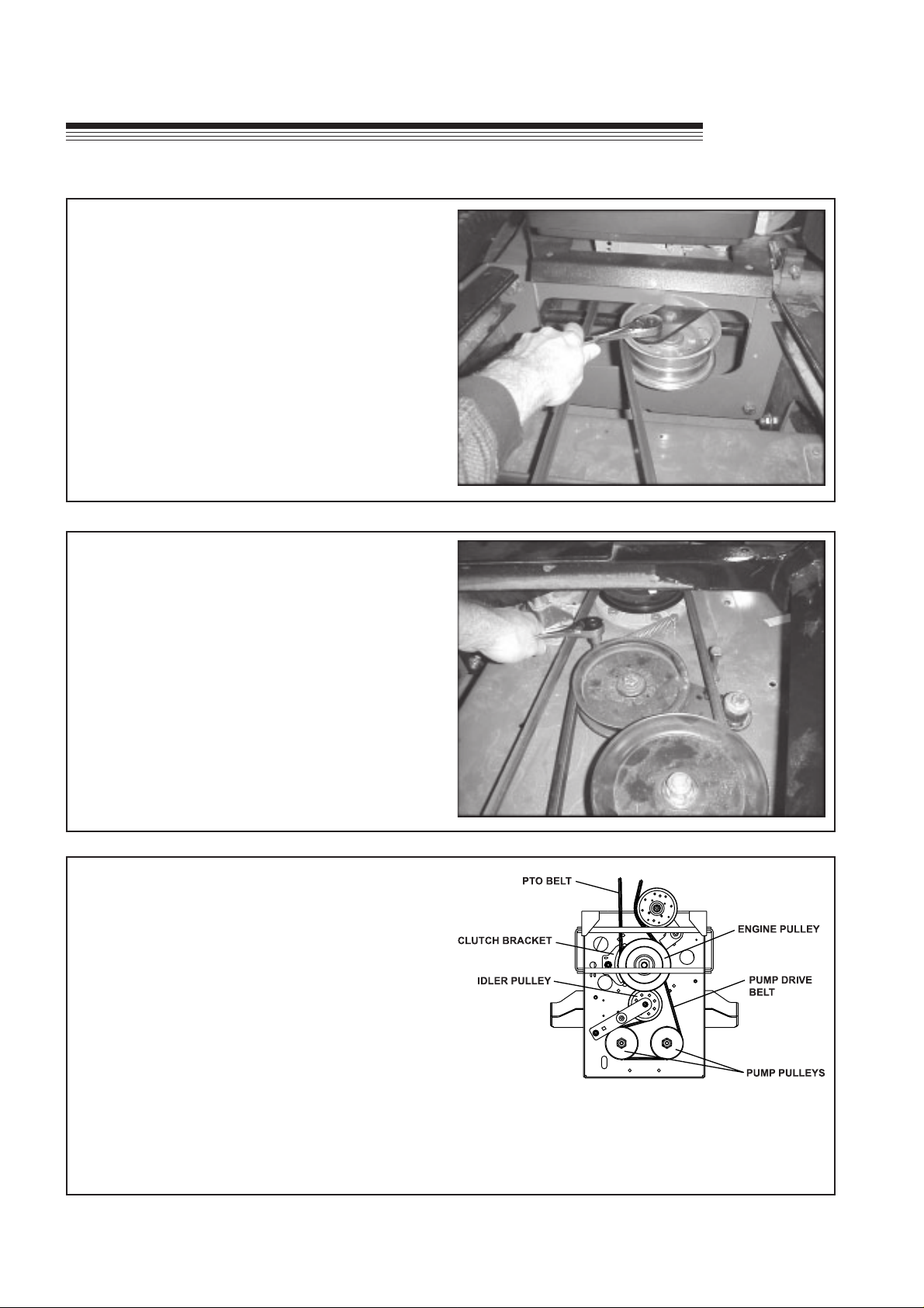
BELT REPLACEMENT
PTO BELT
1. Rotate idler arm using a 3/8" ratchet or breaker
bar and remove belt.
EC
Hydro
Midsize
CUTTERDECK BELT
1. Remove PTO belt.
2. Rotate idler arm using a 3/8" ratchet or breaker
bar and remove belt.
3. Replace in the reverse order.
PUMP DRIVE BELT
1. Remove PTO belt from the engine clutch.
2. Disconnect the clutch wire harness.
3. Unbolt clutch bracket from clutch and rotate the
clutch to allow enough clearance to remove the
clutch bracket.
4. Rotate idler arm using a 3/8" ratchet or breaker
bar inserted into the square hole in the idler arm.
5. Remove pump drive belt.
6. Replace by following steps in reverse order.
GB-24
View under engine deck
Page 27

EC
Hydro
Midsize
PARTS SECTION
PARTS
SECTION
GB-25
Page 28

UPPER ENGINE DECK ASSY
EC
Hydro
FIGURE 1
Midsize
Parts-26
Page 29

EC
Hydro
Midsize
4122450-01
UPPER ENGINE DECK ASSY
FIGURE 1
ITEM PART NO. DESCRIPTION QTY
1-1 2721520 CAP-FUEL GASOLINE 3.5 1
1-2 4116345 TANK-FUEL 1
(INCLUDES ITEMS 3 & 4)
1-3 48310 S BUSHING,FUEL TANK 1
1-4 38540 S FUEL SHUT-OFF VALV 1
1-5 88042N HOSE CLAMP 2
1-6 48016-8A HOSE,.25IDX.50ODX17" 16.5"
1-7 38666 FILTER, FUEL 1
1-8 2721105.2 WLDMT-ENGINE DECK 1
1-9 64123-39 BOLT-HEX 1/2-13X1-1/4 8
1-10 64229-05 LOCKNUT, 1/2-13 NYLON 8
1-11 4116244 GUARD-MUFFLER 1
1-12 64163-31 WASHER 4
1-13 64006-03 LOCKWSHR-HELICAL 3/8 4
1-14 64215-04 RIVET-POP IFI# 42 5
1-15 64229-02 LOCKNUT-NYLON 5/16-18 4
1-16 2306138 S-EC HYD RSVR W/LABS 1
1-17 64123-15 BLT-HEX 3/8-16X3/4 4
1-18 2722269.2 HANDLE-LOWER HYD 1
1-19 64018-9 BLT-CRG 5/16-18 X 3/4 4
1-20 38542 CLAMP-DOCU TUBE 2
1-21 64006-01 LOCKWSHR-HELICAL 1/4 2
1-22 64123-89 BLT-HEX 1/4-20 X 3/4 2
1-23 38061A COVER 2
1-24 2306144 S DOCU TUBE W/LAB 1
1-25 4116243 COVER-MUFFLER 1
1-26 * 4114119 ENGINE-15HP KAW ES 1
2722214 FILTER-OIL
2722207 FILTER-AIR
2722208 FILTER-PRE
4116332 MUFFLER-15HP KAW EC
ITEM PART NO. DESCRIPTION QTY
(SERVICE MANUAL 15 HP KAW #99920-2129-03)
1-27 64211-01 WSHR-ALUM,BACKING 2
1-28 64215-02 RIVET-POP IFI# 44 2
1-29 64205-018 BLT METRIC M8-1.25X15 1
1-30 64002-04 LOCKWASHER, EXT. 5/16 1
* AVAILABLE THROUGH KAWASAKI DEALER
Parts-27
Page 30

LOWER ENGINE DECK ASSY/CLUTCH
EC
Hydro
FIGURE 2
Midsize
Parts-28
Page 31

EC
Hydro
Midsize
4122450-02
LOWER ENGINE DECK ASSY/CLUTCH
FIGURE 2
ITEM PART NO. DESCRIPTION QTY
2-1 2721647 PULLEY-4.50E.O.D. 1
2-2 64163-31 WASHER, 25/64 X 1 X 12 5
2-3 2721110 CLUTCH-ELECTRIC 1
(INCLUDES ITEM 30)
2-4 2721331.7 WLDMT-CLUTCH STOP 1
2-5 2721642 BELT-HA 49.0 1
2-6 2722244 PULLEY- A SECTION 4.50 2
2-7 38304-03 BRG-FLANGED PLASTIC 1
2-8 4121540 PIN-CLUTCH 1
2-9 64139-21 BLT-WLF 3/8-16X3/4 1
2-10 2721641.7 WLDMT-IDLER ARM 1
2-11 4116712 PIN-PIVOT 1
2-12 64163-65 WASHER 0.890 X 1.375 6
2-13 64123-70 BOLT-HEX 3/8-16X1-1/2 1
2-14 64123-138 BLT-HEX 3/8-16X3-3/4 1
2-15 64229-03 LOCKNUT-NYLON 3/8-16 3
2-16 2308000 PULLEY-IDLER 4.00 EOD 1
2-17 33148-01 SPACER 1
2-18 38219 SPRING-TENSION 1
2-19 64123-87 BLT-HEX 3/8-16 X 1-3/4 1
2-20 64141-4 NUT-WLF 3/8-16 3
2-21 * 4121560 KIT-BRAKE POLE 1
2-22 64197-005 BLT-TDFM 3/8-16X1-1/4 4
2-23 64123-155 BLT-HEX 7/16-20 X 3 1
2-24 64006-06 LOCKWSHR-HELICAL 7/1 1
2-25 64123-54 BOLT, 5/16-18X3/4 HEX 2
2-26 64163-55 WASHER .328X.75X14 GA 2
2-27 64229-02 LOCKNUT-NYLON 5/16-18 2
2-28 64164-12 1/4X1/4X1 SQ END KEY 1
2-29 64123-75 BOLT, 3/8-16X3 HEX 2
2-30 2720949 ASSY-CLUTCH WIRE 1
2-31 2721615 PUMP-HYDRO LH 1
2-32 4112782 PUMP-HYDRO RH 1
2-33 2721541 PULLEY-IDLER 5 IN 1
2-34 2721401.7 WLDMT-IDLER ARM 1 235 64163-61 WSHR .81X.406X16GA 1
2-36 64123-16 BLT-HEX 3/8-16X1-1/4 4
2-37 2188131 SPRING-EXTENSION 1
2-38 2721105.2 WLDMT-ENGINE DECK 1
2-39 4116691 PIN-PIVOT 1
2-40 64268-03 NUT-FL NYL LOCK 3/8-16 4
2-41 64044-6 SCREW-SET 5/16-18X1/4 4
2-42 64238-03 KEY-MET 5MM SQ X 28 2
2-43 64209-09 WASHER-CONICAL SPRING 2
2-44 64163-51 WSHR.453X1.38X7GA 1
2-45 64205-013 BLT-MET M6-1 X 12 2
2-46 64221-04 E-RING.875 2
ITEM PART NO. DESCRIPTION QTY
* NOT ILLUSTRATED
Parts-29
Page 32

DRIVE WHEELS
EC
Hydro
FIGURE 3
Midsize
Parts-30
Page 33

EC
Hydro
Midsize
4122450-03
DRIVE WHEELS
FIGURE 3
ITEM PART NO. DESCRIPTION QTY
3-1 2721105.2 WLDMT-ENGINE DECK 1
3-2 2721620.7 WLDMT-HUB 2
3-3 2721956 ASSY-WHEEL 16 X 7.50 X 8 2
2721956-01 TIRE-16X7.50 X 8 MLTI TRC 1
2721956-02 WHEEL W/ DUAL VALVES 1
3-4 64267-01 NUT-HEX FLANGED 1/2-208
3-5 64025-06 NUT-HEX 3/4-16 2A 2
3-6 2308051 MOTOR-WHEEL ROSS MF2
3-7 64141-13 NUT WLF 1/2-13 8
3-8 64164-28 #808 WOODRUFF KEY 2
3-9 64123-72 BLT-HEX 1/2-13X2-1/2 8
ITEM PART NO. DESCRIPTION QTY
Parts-31
Page 34

P ARKING BRAKE
EC
Hydro
FIGURE 4
Midsize
Parts-32
Page 35

EC
Hydro
Midsize
4122413-04
P ARKING BRAKE
FIGURE 4
ITEM PART NO. DESCRIPTION QTY
4-1 2721637 WLDMT-BRAKE SHAFT 1
4-2 33103 SWIVEL 1
4-3 64168-2 COTTER-HAIRPIN.08X1.192
4-4 64141-4 NUT-WLF 3/8-16 2
4-5 64123-171 BOLT-HEX 3/8-16X3-1/2 1
4-6 2188131 SPRING-EXTENSION 1
4-7 2183071-01 SPACER-15.88X10.32X16 2
4-8 64171-2 WAVE WASHER 1
4-9 2188145 BEARING-.75ID 2
4-10 64123-54 BOLT, 5/16-18X3/4 HEX 4
4-11 64141-6 NUT, 5/16-18 4
4-12 2721725.7 WLDMT-SCRUBBER 2
4-13 64061-09 ROLL PIN-3/8 X 2 4
4-14 64229-03 LOCKNUT-NYLON 3/8-16 1
4-15 4121387 ROD-BRAKE 1
4-16 2721632.7 LEVER-BRAKE 1
4-17 38404-01 GRIP-CONTROL LEVER 1
4-18 64123-82 BOLT-HEX 3/8-16X2-1/2 1
4-19 64163-02 WSHR-.321 X .593 X 11GA 1
ITEM PART NO. DESCRIPTION QTY
Parts-33
Page 36

ELECTRIC START UPPER HANDLE
EC
Hydro
FIGURE 5
Midsize
Parts-34
Page 37

EC
Hydro
Midsize
4122450-05
ELECTRIC START UPPER HANDLE
FIGURE 5
ITEM PART NO. DESCRIPTION QTY
5-1 PL5029 GRIP-HANDLE 2
5-2 * 2308121 ADHESIVE-3 GRAM TUBE 1
(USE WITH PL5029 GRIP)
5-3 128010 KEY SWITCH 1
5-4 64152-46 SCR-SLT HH 10-24X1/2 2
5-5 4122157 S UP HNDL W/LBS 1
5-6 2303023 CONNECTOR-OP 2
5-7 4122104 ROD-HANDLE LINK, LH 1
5-8 4122107 ROD-HANDLE LINK, RH 1
5-9 64168-2 COTTER PIN.08X1.19 4
5-10 64197-002 BLT-TDFM 1/4-20X3/4 2
5-11 33030-09 IDLER-BUSHING 2
5-12 4122056 WLDMT-OP PRESENCE 1
5-13 108208 SWITCH DBL POLE 1
5-14 64123-50 BOLT, 3/8-16X1 HEX 4
5-15 2722269.2 HANDLE-LOWER 1
5-16 64141-4 NUT-WLF 3/8-16 6
5-17 64025-15 NUT-HEX #10-24 KEPS 6
5-18 38357-04 CONTROL-THROTTLE 1
5-19 38371-01 BRG-NYLINER 3/8 2
5-20 2302152.7 HNDLE-OP PRESENT 2
5-21 2721505 SWITCH-PTO 1
5-22 64163-83 WASHER-.406 X 1.00 X.25 2
5-23 64163-03 WSHR-.256IDX.62ODX18 2
5-24 64188-44 PIN-CLEVIS 3/16 X 2.25 2
5-25 64175-01 PUSHNUT-3/16 ROD 2
5-26 38371-03 BRG-NYLINER 3/16 4
5-27 64197-015 BLT-TDFM 10-32X1/2 4
5-28 2308094 SWITCH-NCNC DBL POLE1
5-29 4122096 SPRING-TENSION 2
5-30 64229-01 LOCKNUT-NYLON 1/4-20 4
5-31 64225-03 U-BOLT 2
5-32 2722062.7 BRACE-HANDLE 2
ITEM PART NO. DESCRIPTION QTY
* NOT ILLUSTRATED
Parts-35
Page 38

TRACTION CONTROLS
EC
Hydro
FIGURE 6
Midsize
Parts-36
Page 39

EC
Hydro
Midsize
4122450-06
TRACTION CONTROLS
FIGURE 6
ITEM PART NO. DESCRIPTION QTY
6-1 2722426 GRIP-TRACTION LOCK 2
6-2 38189 SPRING-COMPRESSION 2
6-3 64061-37 ROLL PIN-1/8 X 1.00 SS 2
6-4 2303076 STUD-DOUBLE ENDED 2
6-5 62464-5A
6-6 33243 SPACER 2
6-7 2722242 LATCH-ROLLER LH 1
* 2722243 LATCH-ROLLER RH 1
6-8 64229-02 5/16-18 NYLON LOCKNUT 4
6-9 64229-01 LOCKNUT NYL 1/4-20 2
6-10 2308002 BRG-RADIAL W/STUD 2
6-11 64175-01 PUSH NUT 2
6-12 2308080 BEARING SELF ALIGNED 2
6-13 2721843.7
6-14 64168-2 HAIRPIN COTTER 7
6-15 2308065 SPRING EXTENSION 2
6-16 2721660 WLDMT-PUMP ARM RH 1
* 2721622 WLDMT-PUMP ARM LH 1
6-17 2722305 ROD-SPEED CONTROL 2
6-18 2721842.7 ARM-LH SPEED CONTROL1
6-19 64163-06
6-20 85010N ZERK, 1/4-28 STR 2
6-21 64163-61 WSHR .81X.406X16GA 2
6-22 64061-28 ROLL PIN 3/16 X 1 1/4 2
6-23 2721617.7
6-24 2722269.2 HANDLE-LOWER 1
6-25 64123-50 BOLT, 3/8-16X1 HEX 2
6-26 2306081.7 WLDMT PUMP ARM 2
6-27 * 2308121 ADHESIVE 1
(USE WITH 38009N GRIP)
WASHER,THRUST 5/16X3/4
ARM-RH SPEED CONTROL
WSHR.768/.756X1.25X14GA
WLDMT-SPEED CONTROL
ITEM PART NO. DESCRIPTION QTY
6-47 38404-01 GRIP,CONTROL LEVER 1
6-48 2308076-02 BEARING-PLASTIC 2
6-49 64192-04 SET SCREW 5/16-18X5/8 2
6-50 2303058
2
1
2
2
6-51 64123-02 BLT HEX 3/8-24 X 1 2
6-52 64006-03
6-53 64144-16 RING,CLIP-.75X.062 2
6-54 38524 KNOB-4 PRONG 3/8-16 1
6-55 2721854
6-56 64123-69 BOLT-5/16-18X1-1/2 HEX 2
6-57 118047-09 BUSHING-FLIP LOK.75ID 2
6-58 2721853
6-59 138011 BALL JOINT 1
6-60 64001-2 NUT 3/8-16 1
6-61 2721844
TRACTION LOCK ASSY'S ARE ALSO AVAILABLE
4113565 S-TRCTN LOCK ASSY RH 1
(INCLUDES ITEMS 1-4, 6, 7, 9-12)
4113564 S-TRCTN LOCK ASSY LH 1
(INCLUDES ITEMS 1-4, 6, 7, 9-12)
ECCENTRIC SHAFT W/ZRK
WASHER, 3/8 HELICL LCK
STUD-3/8-16X 3/8-24 4.5LG
SPACER-19.05X10.31X27LG
BUSHING-SPEED CONTROL
* NOT ILLUSTRATED
2
2
1
1
1
6-28 64123-100 BOLT-3/8-16X2-1/4 HEX 1
6-29 64123-68 BLT-HEX 5/16-18 X 1 2
6-30 64139-13 BLT-WLF 5/16-18X1/2 4
6-31 64163-02
6-32 38372 BEARING BALL 4
6-33 2720312 SPRING-COMP IDLER PLT1
6-34 33103 SWIVEL 4
6-35 4122108 ROD-TRCTN CNTRL,HYD 2
6-36 31032 LEVER TRACTION CNTRL 2
6-37 38009N GRIP TRACTION CNTRL 2
6-38 64163-31 WASH 25/64X1X12 GA 4
6-39 64188-34 PIN-CLEVIS 3/16 X 2.25 2
6-40 64141-6 NUT-WLF 5/16-18 6
6-41 4117212 SPRING EXTENSION 2
6-42 64123-70 BOLT-HEX 3/8-16X1-1/2 4
6-43 64141-4 NUT-WLF 3/8-16 10
6-44 64123-202 BLT-HEX 3/8-16 X 9 1
6-45 64229-03 NUT-NYLOCK 3/8-16 3
6-46 2308066 FRICTION WASHER 2
WSHR 21/64X19/32X11 GA
11
Parts-37
Page 40

ELECTRIC ST ART BATTER Y
EC
Hydro
FIGURE 7
Midsize
Parts-38
Page 41

EC
Hydro
Midsize
4115262-07
ELECTRIC ST ART BATTER Y
FIGURE 7
ITEM PART NO. DESCRIPTION QTY
7-1 64229-02 LOCKNUT-NYLON 5/16-18 2
7-2 64163-29 WASHER 2
7-3 128035 COVER-BATTERY 1
7-4 2721105.2 WLDMT-ENGINE DECK 1
7-5 64123-54 BOLT, 5/16-18X3/4 HEX 2
7-6 112386
7-7 108055 BATTERY 1
7-8 108061-16
7-9 64025-02 NUT-HEX 5/16-18 2
7-10 4115331 S-TRAY, BATTERY 1
7-11 2722227-03
7-12 2722202.7 SUPPORT-BATT TRAY 2
7-13 64197-016 BLT-TDFM 3/8-16X1/2 8
7-14 123026 ROD,BATTERY HLD DWN 1
7-15 38665 SOLENOID 1
7-16 64152-23 1/4-20X3/8 LG SP SCREW 2
7-17 108061-15 CABLE-BATTERY 6.5 RED 1
7-18 64141-2 NUT-WLF 1/4-20 1
BOOT-BATTERY TERM POS
CABLE-BTTRY 31.5 BLACK
CABLE-BTTRY W/CONDUIT
1
ITEM PART NO. DESCRIPTION QTY
1
1
Parts-39
Page 42

HYDRAULICS
EC
Hydro
FIGURE 8
Midsize
Parts-40
Page 43

EC
Hydro
Midsize
4115262-08
HYDRAULICS
FIGURE 8
ITEM PART NO. DESCRIPTION QTY
8-1 58026-01 3-WAY CONNECTOR 2
8-2 108029 PLUG, MAGNETIC 1
8-3 158058-04 FITTING-90 BARB, ADJ. 2
8-4 108205-02
8-5 88042-04 CLAMP-HOSE 5/8" 12
8-6 2720396 FLTR, 25 MCRN SM CAM 1
8-7 69060-01 FTG-BARB 9/16 X 3/8 ST 2
8-8 69216.7 CAP-RESERVOIR 1
8-9 64123-60 BOLT, 1/4-20 X 2 HEX 2
8-10 64229-01 LOCKNUT-NYLON 1/4-20 2
8-11 2306138 S HYD RESER W/LABS EC1
8-12 2308051 MOTOR WHEEL ROSS 2
8-13 2692300-01
8-14 2692300-02
8-15 4112782 PUMP-HYDRO LH 1
(SEE FIG 10 FOR PARTS BREAKDOWN)
8-16 2721615 PUMP-HYDRO RH 1
(SEE FIG 10 FOR PARTS BREAKDOWN)
(69053-05 IS A SERVICEABLE LENGTH OF 55")
8-17 69053-05 3/8 HI TEMP HOSE 17.0" 1
8-18 69053-05 3/8 HI TEMP HOSE 5.0" 1
8-19 69053-05 3/8 HI TEMP HOSE 5.0" 1 820 69053-05 3/8 HI TEMP HOSE 7.5" 1
8-21 69053-05 3/8 HI TEMP HOSE 6.8" 1
8-22 69053-05 3/8 HI TEMP HOSE 12.0" 1
ELBW-MALE 45 8X8 37-ORB
HOSE-1/2 37/ORB X 18.5 LG
HOSE-1/2 37/ORB X 18.5 LG
4
2
2
ITEM PART NO. DESCRIPTION QTY
SERVICEABLE HYDRAULIC O-RINGS
GNIR'O'TROPEAS
TRAP
REBMUN
01-160851 81-61/9 60911-160851 61-4/3 80921-160851 41-8/7 01931-160851 21-61/1-1 21941-160851 21-61/5-1 61961-160851 21-8/5-1 02930-160851 21-8/7-1 429-
NOTE:
DO NOT use teflon tape on any hydraulic fittings.
Use a liquid pipe sealant.
EZISDAERHT #865-SA
Parts-41
Page 44

DECALS
EC
Hydro
FIGURE 9
Midsize
Parts-42
Page 45

EC
Hydro
Midsize
4122450-09
DECALS
FIGURE 9
ITEM PART NO. DESCRIPTION QTY
9-1 4122171
9-2 009034760 DECAL-NOISE 100 1
9-3 2000664
9-4 2000655
9-5 2000650 LABEL-BATTERY EEC 1
9-6 2721030 DECAL-RANSOMES 2
9-7 2000685-01
(SIDE DISCHARGE LENGTH 28.4")
(REAR DISCHARGE LENGTH 28.5")
9-8 2000638 LABEL-CON WASHER EEC1
9-9 2000760 LABEL-HANDS/ROCKS EC1
9-10 2000704 LABEL-MIDSIZE PATENT 1
LABEL-CNTRL PNL EC HYD
LABEL-HYDRAULIC MS EEC
LABEL-READ OPRTRS EEC
LBL-RED/WHITE STRPE 55"
ITEM PART NO. DESCRIPTION QTY
1
1
2
1
Parts-43
Page 46

HYROGEAR PUMP
FIGURE 10
EC
Hydro
Midsize
Parts-44
Page 47

EC
HYDROGEAR PUMP
Hydro
2721734-14
FIGURE 10
Midsize
4112782 PUMP-HYDRO LH ILLUSTRATED AS SHOWN
2721615 PUMP-HYDRO RH ILLUSTRATED AS SHOWN EXCEPT GROUP A IS ROTATED 180°
AROUND THE CENTERLINE OF THE PUMP.
ITEM HYDROGEAR PART NO. TEXTRON PART NO. DESCRIPTION QTY
10-1 70516 ----- HOUSING KIT 1
10-2 70517 ----- END CAP KIT 1
10-3 50641 ----- STRAIGHT HEADLESS PIN 2
10-4 50969 2721615-01 FLANGE BOLT M8-1.25 X 60 4
10-5 51232 2721615-02 HOUSING O-RING 1
10-6 2513027 2721615-03 CHARGE PUMP KIT (STD) 1
10-7 50273 2721615-04 STD GEROTOR ASSEMBLY 1
10-8 9004101-1340 2721615-05 O-RING 1
10-10 50095 2721615-06 SOCKET HEAD M6-1.0 X 20 2
10-15 2513030 ----- BYPASS VALVE KIT (BLANK) 1
10-18 70521 2721615-07 PUMP SHAFT KIT 1
10-19 50315 ----- BALL BEARING 17 X 40 X 12 1
10-20 51161 ----- LIP SEAL 17 x 40 x 12 1
10-21 50951 ----- SPACER 1
10-22 50329 ----- RETAINING RING 1
10-25 70331 2721615-08 CYLINDER BLOCK KIT 1
10-29 2003014 ----- BLOCK SPRING 1
10-30 2003017 ----- BLOCK THRUST WASHER 1
10-31 51246 2721615-09 VALVE PLATE 1
10-32 2003087 2721615-10 SWASHPLATE 1
10-34 50551 2721615-11 BALL THRUST BEARING 1
10-37 2003005 2721615-12 TRUNNION ARM 1
10-38 2000015 2721615-13 SLOT GUIDE 1
10-42A 2510027 2721615-14 CHECK VALVE KIT (.031") 1
10-42B 2510050 2721615-15 CHECK VALVE KIT (BLANK) 1
10-44 70403 2721615-16 CHARGE RELIEF VALVE KIT 1
10-49 2513043 2721615-17 TRUNNION SEAL/RETAINER KIT1
10-56 9005110-4400 ----- STRAIGHT THREAD PLUG 1
10-66 9005110-3100 ----- 5/16 SAE PLUG 1
Parts-45
Page 48

CUTTERDECK MOUNTING
EC
Hydro
FIGURE 11
Midsize
Parts-46
Page 49

EC
Hydro
Midsize
4122450-11
CUTTERDECK MOUNTING
FIGURE 11
ITEM PART NO. DESCRIPTION QTY
11-1 2721991.7 PLATE-NUT 2
11-2 64246-04 NUT-WHIZ M12-1.75 12
11-3 64141-4 NUT-WLF 3/8-16 2
11-4 64163-82
11-5 64123-50 BOLT-HEX 3/8-16X1 2
11-6 64263-018
WSHR-FLAT.406X1.44X9GA
BLT-FLG HD M12-1.75 X 30
2
4
ITEM PART NO. DESCRIPTION QTY
Parts-47
Page 50

ELECTRICAL DIAGRAM
EC
Hydro
FIGURE 12
Midsize
Parts-48
Page 51

EC
Hydro
Midsize
2721734-12
ELECTRICAL DIAGRAM
FIGURE 12
ITEM PART NO. DESCRIPTION QTY
12-1 2721110 CLUTCH-ELECTRIC 1
(INCLUDES ITEM 2)
12-2 2720949 ASSY-CLUTCH WIRE 1
12-3 108208 SWITCH DBL POLE 1
12-4 128010 KEY SWITCH 1
12-5 2308094
12-6 148082-20 FUSE 20 AMP 2
12-7 2721505 SWITCH-PTO 1
12-8 2721727 HARNESS-HYDRO MAIN 1
(INCLUDES QTY OF 2 OF ITEM 6)
12-9 38665 SOLENOID-STARTER 1
12-10*108061-15 CABLE-BATTERY 6.5 RED 1
(FROM STARTER SOLENOID TO STARTER)
12-11*2722227-03
(FROM (+) POSITIVE BATTERY TERMINAL
12-12*108061-16 CABLE-BTTRY 31.5 BLACK1
(FROM (-) NEGATIVE BATTERY TERMINAL
SWITCH-NCNC DBL POLE
CABLE-BTTRY W/CONDUIT
TO STARTER SOLENOID)
TO ENGINE BLOCK)
ITEM PART NO. DESCRIPTION QTY
1
1
* NOT ILLUSTRATED
Parts-49
Page 52

ELECTRICAL SCHEMA TIC
EC
FIGURE 13
4115262-13
Hydro
Midsize
Parts-50
Page 53

Page 54

GB
World Class Quality, Performance and Support
Equipment from Ransomes Jacobsen Limited is built to
exacting standards ensured by ISO 9001 registration at
all our manufacturing locations. A worldwide dealer
network and factory-trained technicians backed by
Ransomes Jacobsen Parts Xpress provide reliable,
high-quality product support.
BOB-CAT BUNTON CUSHMAN JACOBSEN RANSOMES RYAN E-Z-GO
Ransomes Jacobsen Limited
Central Avenue, Ransomes Europark, Ipswich, England, IP3 9QG
English Company Registration No. 1070731
www.ransomesjacobsen.com
 Loading...