


RangeVision
ScanCenter 2016.1
1

Introduction........................................................................................................................................................4
System requirements.........................................................................................................................................4
Warnings ......................................................................................................................................................4
Technical specifications.................................................................................................................................5
Package contents ..........................................................................................................................................6
Scanner Assembly .........................................................................................................................................8
Installing software and drivers ......................................................................................................................9
Setting up your computer for the work with the scanner ............................................................................10
Connecting projector .............................................................................................................................. 10
UAC settings............................................................................................................................................ 12
Connecting cameras ................................................................................................................................ 13
Configuring computer parameters .......................................................................................................... 13
Connecting the turntable ........................................................................................................................ 14
Scanner setup...................................................................................................................................................17
First launch of ScanCenter...........................................................................................................................18
Inital setup of cameras and lenses ..............................................................................................................19
Finding a working distance ..........................................................................................................................21
Adjustment of the projector focus...................................................................................................................20
Bringing the cameras together ....................................................................................................................22
Checking the cameras in a horizontal plane.................................................................................................24
Final calibration of the cameras ..................................................................................................................25
Calibration plate .........................................................................................................................................30
Mounting constructions ..............................................................................................................................32
Orienting ....................................................................................................................................................35
Scanning area .............................................................................................................................................36
Adding new plates ......................................................................................................................................36
Calibration for scanning zone №0 ...............................................................................................................37
Scanning..........................................................................................................................................................37
Requirements for the scanned object..........................................................................................................38
2

Scanning principle and methods .................................................................................................................38
Creating a new project ................................................................................................................................39
Determining the correct distance to object .................................................................................................39
Setting exposure of the cameras .................................................................................................................40
Starting and stopping the scanning process.................................................................................................40
Viewing the model ......................................................................................................................................40
Unwanted noise on the 3D model ...............................................................................................................41
Scanning without markers...........................................................................................................................42
Scanning with markers ................................................................................................................................42
Scanning on the rotary table .......................................................................................................................46
Possible problems and their solution ..........................................................................................................47
Settings ................................................................................................................................................... 47
Scanning ................................................................................................................................................. 48
3

Operating system
Windows 7/8/10 64bit
Processor
Intel Core i5 2.0 GHz and better
RAM
Not less than 4 GB
Graphics Card
Graphics card with HDMI output
Other
3 USB-ports
Introduction
Thank you for choosing RаngeVisiоn product.
Please read this manual before using RangeVision 3D scanner. Here are described the procedures for
preparing the scanner, installing the required drivers, calibration procedure, scanning procedure, and tips for
acquiring high-quality three-dimensional object model. Processing of gathered data and export of results is
described in the manual SсаnMerge 2016.1.
Information may be amended from time to time. These changes will be inserted into the new versions of
the manual, or in the additional documents and publications.
System requirements
Warnings
● Do not expose the scanner to liquids.
● Do not use liquid cleaners or aerosol cleaners.
● Do not store or use the scanner in dusty or humid environment.
● Do not expose the scanner and its components to contamination, shock or drops.
● Do not connect power to the faulty wall outlet.
● Do not aim the scanner on the people and animals in order to avoid contact with eyes of the
harmful bright light projector.
● Patterns and holes are provided for ventilation of the scanner to ensure its reliable operation
and to prevent overheating. Do not block or cover the openings.
4

Scanning zone
number
[ 1 ]
[ 2 ]
[ 3 ]
[ 4 ]
[ 0 ]
Scanning Area
(WxHxD) (mm)
460*345*345
300*225*225
133*100*100
66*50*50
850*530*530
3D point accuracy
0.085 mm
0.05 mm
0.03 mm
0.03 mm
0.16 mm
3D resolution:
Standard Plus
0.35 mm
0.23 mm
0.1 mm
0.05 mm
0.7 mm
Advanced
0.3 mm
0.2 mm
0.085 mm
0.043 mm
0.6 mm
Premium
0.18 mm
0.12 mm
0.05 mm
-
0.35 mm
Operating distance
0.9 m
0.52 m
0.3 m
0.27 m
1.1 m
Technical specifications
Rangevision 3D scanner can be equipped with various scan areas sets. The specified values accuracy can
be achieved in compliance with the rules calibration and proper settings of the scanner.
3D scanner RаngeVisiоn is not a metrological tool for measuring.
5

Model
Standard Plus
Advanced
Premium
Resolution of cameras
1,3 Mpix
2 Mpix
5 Mpix
Diagonal of the matrix
1/1.8”
1/1.8”
2/3”
Scanning time
~ 7 sec
~ 12 sec
~ 15 sec
Model calculation time
~ 5 sec
~ 10 sec
~ 20 sec
Scanning of dark objects
- + +
Package contents
RаngeVisiоn 3D scanner is supplied in a plastic box with lodgement, optionally can be supplied in a
protected road hard case.
Camera tripod is placed in a separate bag.
The scanner is equipped with at least one scanning area. Scanning area is a set of interchangeable optics,
calibration plate and stand for the calibration plate. One of the optics set, as a rule, is installed in the cameras.
6

№
Name
Amount
1
Scanning module:
Installation construction with projector
1
Cable kit for connection to a PC (2 USB + HDMI)
1
2
Machine vision camera
2 3 Tripod
1 4 Calibration plate
1-4*
5
Kit of interchangeable optics
1-5*
6
Stand for the calibration plate
1-2*
7
USB disk with the software
1
8
The electronic key
1
9
Matting spray
1
10
Markers for scanning
1
11
Power Cord 5 m
1
12
USB hub
1
13
Hex key
1
14
Rotary table + cables
1*
Package:
* - depends on the equipment
7

Before the first start
Prior the first connection and use of RangeVision 3D scanner you need to install the drivers, software and
set up your PC.
After this, assemble the scanner and connect it to the computer.
Scanner Assembly
Carefully get the scanning module and all accessories out of the plastic case.
● Set the tripod on the flat and stable surface.
● Fit the scanning module 1 on the tripod.
● Install module 2 on the front part of scanning camera. Cameras must rotate around their axis
to each other, and not in different directions.
● Install the camera lens kit 5 (if not yet installed). Choice of lenses is described in the section
dedicated to Scanner Setup.
8

● Connect USB cables to the cameras and to the computer. Cameras should be connected to
your PC after the drivers installation without any hubs or adapters.
● Connect the power cord 11 (5m cable) to the projector and turn on the projector.
● Connect HDMI cable to the projector and to the computer.
● Insert the electronic key 8 into a free USB port.
● Connect the rotary table 14 (if equipped) to your computer using the USB cable, connect the
power cord (3m cable).
Installing software and drivers
Get the RаngeVisiоn software (equipped with the scanner) and run the installer - RаngeVisiоn SсаnCenter
setup.
Following the prompts, select the desired language, type and path for installation. After the files have been
copied install drivers and graphics libraries, necessary for the correct operation of RangeVision 3D scanner.
9

Note
If the second monitor (projector) is not defined by the system - check the cable connections
and restart the computer.
Also, try to connect the cable to your computer when the projector is on, if it was off earlier.
After the completion of the work of installer on your PC should appear Rаngevisiоn SсаnCenter software
and IDS Camera Manager.
Setting up your computer for the work with the scanner
For the correct operation of Rаngevisiоn 3D scanner you will need to setup your computer. This procedure
is performed once before the first use of the scanner.
Connecting projector
After connecting the projector it should be displayed in the system.
If the computer has several video outputs, define the one to be used.
● Right click on the desktop, select Screen resolution
● Select the Display option, or by clicking your mouse on the digit 2, second monitor.
● Choose the Expand these displays in the Multiple displays drop-down list.
10

● Choose the Resolution of your projector:
○ Acer P1500: 1920*1080
○ Acer X13**: 1280*800
The projector, mounted on a RangeVision 3D scanner, is pre-configured to work correctly. However, in the
rare cases when the power is turned off, you may encounter the case when settings of your projector are
reset, which can have an adverse impact on the scanner operation. If this happens, you need to adjust your
projector using the control buttons on its body.
You must set the following parameters:
In the tab "Color":
● Display mode — User.
● Brightness — 30.
● Contrast — 30.
● Dynamic black — off.
● Gamma – 1.
In the tab "Image":
● The format of aspect ratio - auto
● Trapez. distort. – 0.
● Sharpness – 0.
● Range of HDMI colors — auto
In the tab "Management":
● Battery saving - off
11
While using special light filters (Blue Light) some types of scanners may be set up at user mode of color
temperature (“hardware controlled” blue illumination). Starting with software version 2016.1 ``program``
blue illumination is used, along with this the projector must be set up as mentioned above. When using light
filters there is no need to change user settings of projector color temperature for previous versions.
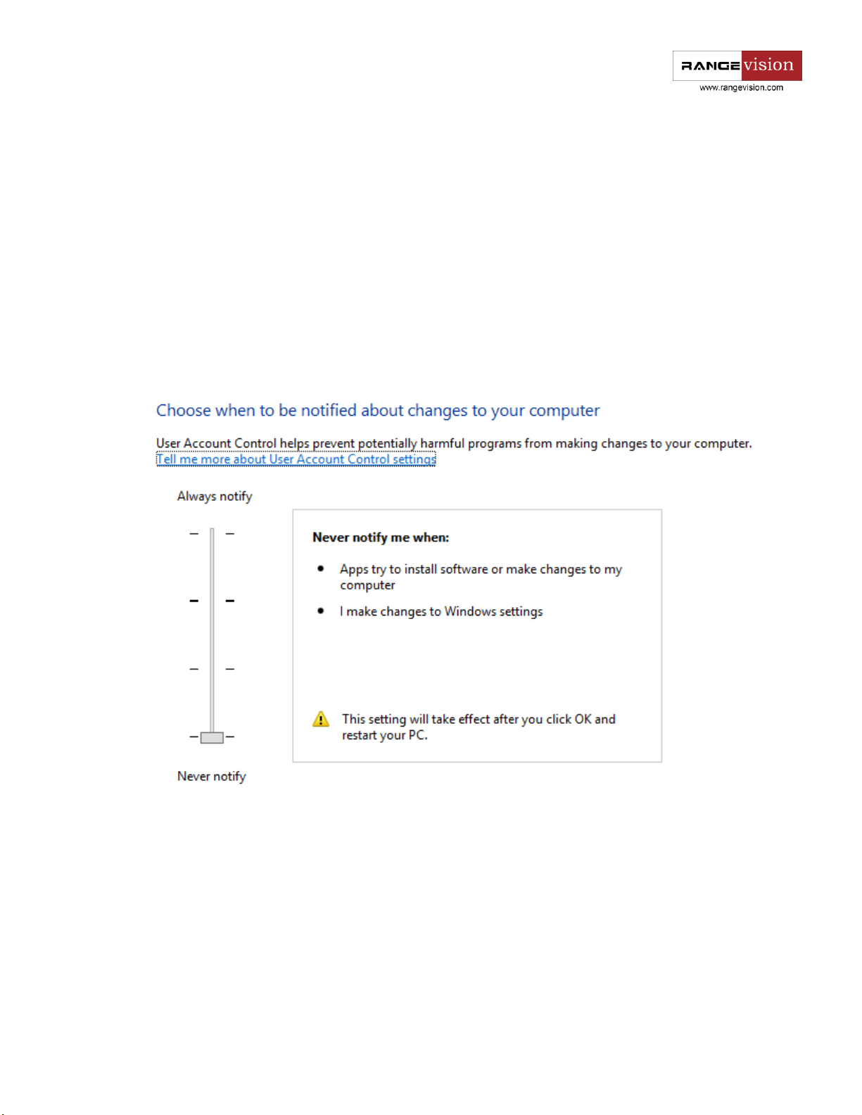
UAC setting
For the convenience of the program operation it would be desirable to change user account control
settings.
To do this go to the Control Panel - User Accounts - Change UAC settings.
Lower the slider down as much as possible and save the changes.
12
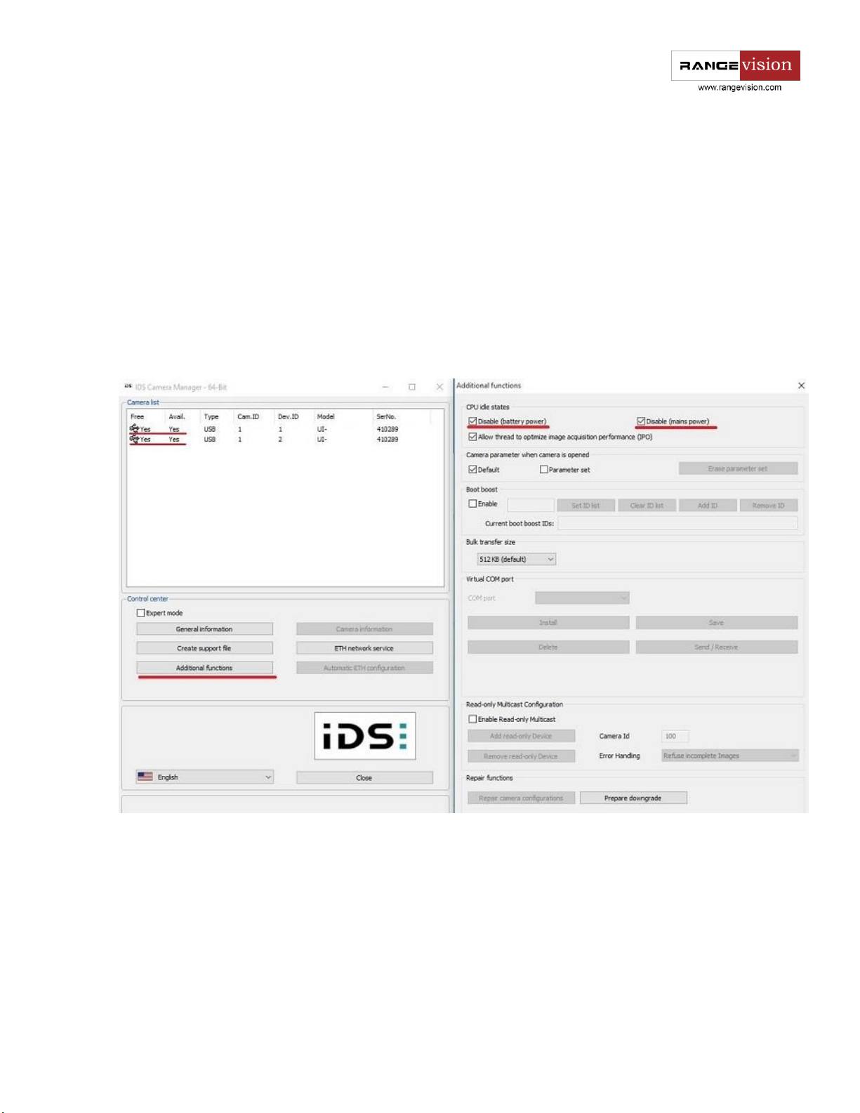
Connecting cameras
After installing the camera drivers IDS Camera Manager software should appear on your PC. Do not
connect the cameras before you install the drivers! Connect cameras to USB-ports of your PC and run the IDS
Camera Manager.
The application will display connected cameras and their state. Cameras must be available (free). If one
of the cameras in unavailable, most likely it is used by some third-party application, for example Skype. Turn
off the software, which uses cameras and check camera availability in IDS.
Go to the menu item Additional settings and disable the Idle state, as in the figure below.
Configuring computer parameters
To avoid a recurrence of the problems during the scanner operation, you must turn off the screensaver
and sleep mode.
By clicking right mouse button on the desktop, select Personalize - Screensaver and turn off the
screensaver, disable turning off the display and putting the computer in sleep mode.
13

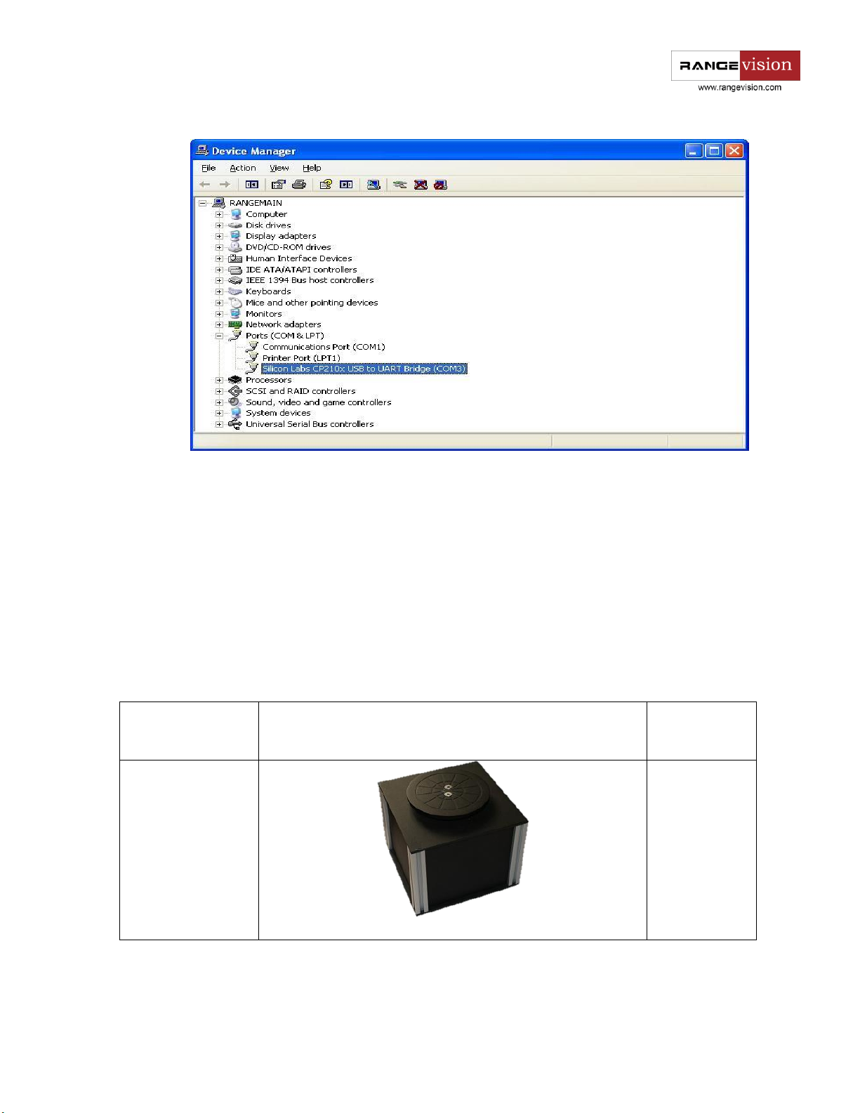
Connecting the turntable
Before scanning on the turn table you must install the table driver, connect the power supply and connect
the table to your computer using the USB cable.
Scanner may be equipped with different types of turn tables , with additional power supply or without it
and depending on the controller the name of connected device in Device Manager may be different, for
example Silcon Labs, Arduino Uno, Rangevision Table and so on
Go to the Device Manager in the computer properties and look the number of COM port that is used by
turn table. Then (look up first launch of ScanCenter) in configuration of the scanner (Settings - Configuration
setup - Turn table) specify the identified port number in the column Device number, using the table below
define and choose the needed number of turn table in Device Configuration Settings.
14
Model
Type
Additional
power supply
Default
(till 01.2016 г.)
Yes
15

TS-12
No
TL-30
Yes
Create a new one or open an existing project on the turn table. If the table is connected and all the settings
are correct, you will see the graphic mode of the table platform in the 3D model preview area. In case of an
error you will see the corresponding message.
Check the connection of turn table, driver installation and proper COM-port number in settings of the
scanner configuration.
16

In order to test the operation turn the table at a small angle. To do this select the menu item Settings →
Table calibration. Enter the value of the angle and press Turn. Table must rotate clockwise, when viewed from
the top. If the table is rotated in the other direction, change the settings of the parameter Change direction
in the configuration settings.
In contrast to the other modes, before scanning on the turn table you should first evaluate its axis (perform
the calibration of the table), to ensure that the scanner knows where the axis of the table is located for the
automatic alignment of fragments. Second calibration is needed, if during scanning the reciprocal positioning
of the scanner or of the table was changed.
17

Scanning zone
The approximate size of
calibration plate, plate №
Lenses
№1
414 mm, №1
12,5 mm
№2
237 mm, №2
12,5 mm
№3
95 mm, №3
16 mm
№4
47 mm, №4
25 mm
№0
414 mm, №1
9 mm
Scanner settings
After preparatory actions on setting up the computer you should carry the scanner setting procedure.
Before beginning the configuration select the desired scan area (zone), depending on the object scanned.
Scanning area is a set of interchangeable optics, calibration plate and stand for the calibration plate, which
help to configure the scanner to scan a certain area. In the majority of cases scan area is correctly matched,
if the size of the object approximately equals to the size calibration plate.
Install lenses with Blue Light filters (if present) on the camera, which correspond to the selected scan zone
(see table below). It`s forbidden to use the scanner without light filters with operating blue illumination!
Securely tighten the lenses and light filters. Place the calibration plate on the stand in front of the scanner.
Size of calibration plate is specified in the table on the back side of each plate.
First launch of ScanCenter
Turn on the projector and connect the scanner to the computer. In IDS Camera Manager check the
connection and cameras availability. Run Rangevision ScanCenter. In order for program to work properly
you need to run it as Administrator.
Equipment selection dialog appears automatically during first start or is available on the tab Settings →
Equipment setup.
Specify the projector used in your scanner. Projector model may be specified in settings Screen Resolution.
Correctness of projector choice and subsequently of its type and resolution directly impacts the scanning
quality.
18

Note
If the cameras are not installed or not connected, instead of images you will see black or
gray screen.
You must also check whether such programs as ICQ, Skype, Sippоint or similar software use
one of the cameras as a web camera.
Caution!
Check that the right-hand camera represents the image on the right, and the left-hand
camera - the one on the left. Right camera is the one that is located on the right-hand, if you
stand behind the scanner face to scanned object.
If the cameras have been interchanged, change the status of parameter Swap cameras in
the Cameras tab in Hardware setup (Service → Hardware setup).
The scanner defines automatically the models of cameras. If you know the model of the cameras - please
specify it, it will accelerate program launch . Choice of the cameras corresponds to the name of the scanner
model (Standard Plus, Advanced, etc.).
In the case if all the settings are correct, after starting the program you should see the image from the
cameras in the main application window, and the projector will start projecting cross.
Initial setup of cameras and lenses
When you first set up the scanner image from the cameras may not be in focus or can be too bright or too
dark. Adjust camera lenses, so that the image of the cameras displays the calibration plate in front of the
scanner.
19

Lens adjustment is carried out by the following elements:
1. The focus tuning ring
2. The iris tuning ring
3. The focus ring retention screw
4. The iris ring retention screw
Do not completely remove the retaining screws of the lens rings, it is
enough just to loosen them. After you finished tuning the lens, lock the
adjustment rings with the screws provided.
20

Note
To test the found distance D there is a formula L=D/3, where D – distance to the field, and
L – distance between the objectives of the cameras. The measured distance should not differ
much from the value calculated by the formula. If there is a strong difference, check the
positioning of cameras, and the focal length of lenses.
Finding a working distance
The scanner has own working distance (distance to the object) for each
scanning area. When you configure your scanner, this distance is
determined by calibration plate.
To find a working distance place the calibration plate in front one of the
cameras (see diagram). The camera must be installed parallel to the
projector beam. Turn on the White light projector mode. If necessary,
adjust sharpness and lens iris, configure the image, so that you can clearly
see the calibration plate. By moving the field closer to or further away from
the camera, align the far markers of calibration plate with blue mesh on the
camera view, as shown in the figure below. Blue vertical lines in the camera
view must match the marks on the calibration plate.
Adjustment of the projector focus
During the scanner operation the projector project structured light to the object - coded lines and stripes.
To ensure that the lines are sharp, the projector must be focused on the working distance of the scanner.
To focus the projector install calibration plate in front of the scanner at the found distance D.
21

Note
Minimum light area of Acer projectors (zoom ring in the last position) allows you to configure
focus for any calibration plate.
For other projectors, depending on the scan area, using the zoom ring you can select that
area of light, in which all the plate will be lit, or use special lenses.
Note
If the images from the cameras are very dark, tune the iris and the focus on the cameras.
By switching the mode "Lines and Stripes", adjust the focus of the projector, so that the lines on the
calibration plate were as sharp as possible. Using the zoom ring set the minimum possible area of projector
light in such a way that the whole field is lit with a small margin to the height.
After changing the illumination area check the projector focus.
Bringing the cameras together
For the work of the scanner it is necessary to point both cameras to the same position on the specified
working distance. Install the calibration plate in front of the scanner on the found working distance D (if you
changed its position after the projector focusing procedure).
Turn on the Cross light mode and aim the scanner to the calibration plate. It is not necessary to combine
cross with marks on the plate at this stage, the focused projector should be projecting a cross on any surface,
located at the working distance D from the scanner.
Install the cameras in position, corresponding to selected scan area. It is necessary to align black risks on
the front of the scanner, labelled 1,2,3,4 , with inner edge of the camera mounting plate. To do this, loosen
the mounting bolts and move the camera to the desired position. Position 4 is similar for both cameras. On
the image below the cameras are set in the position for scanning area №2.
22

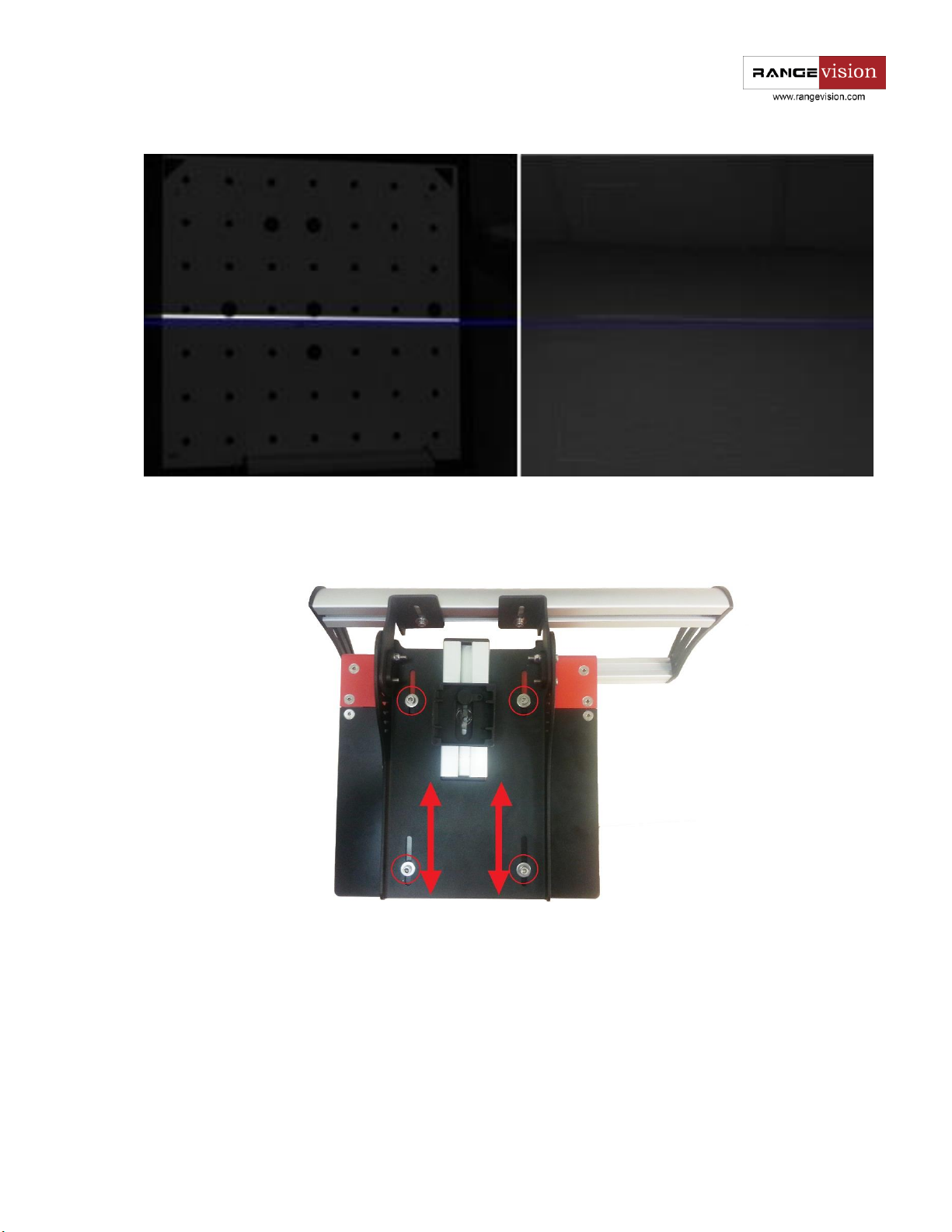
Rotate the cameras on the bar so that the vertical line of the light cross lies approximately on the central
vertical blue line in the both camera views as shown below.
Adjusting the position of the camera in a horizontal plane is controlled by the change of front frame. To
do this - loosen the adjustment screws and, by changing the position of a frame, align the middle horizontal
blue line on the camera view with a horizontal line of projected cross.
23

Note
If cameras are lowered too low, first adjust the horizontal position, and then bring the
cameras together in the vertical direction.
A small deviation between the right-hand and left-hand cameras in height does not affect
the scan quality, select the middle position between the cameras.
Tighten the fixing screws after you are done with positioning cameras.
Checking the cameras in a horizontal plane
For the correct operation of the scanner projector beam and optical axis of cameras must be lying in one
plane. This is done through regulating the position of cameras in relation to the projector during scanner
assembly. During transport or other mechanical action the position may alter, leading in some cases to worse
scanning quality. The correctness of the settings is easy to verify by means of a projecting Cross after bringing
cameras to a remote object. The horizontal line of the cross still must match the horizontal line of the blue
markings on the view from cameras.
24
If the projected line and marking line have a large discrepancy at different distances to the object, adjust the
position of the projector relative to the cameras. To do this, loosen the body at the bottom of the scanner
and pick the position, in which the check will be carried out successfully.
Final calibration of the cameras
After setting the position of the cameras, align the projected cross with central mark on the calibration
plate.
25

Note
Please note, at the correct location of plate at a distance D the vertical line of cross will match
the central vertical blue line on the view from the cameras. Otherwise, you will notice the
difference in one direction or the other.
Before setting the exposure, adjust sharpness of the lenses.
To do this:
● turn on the "Black light" projector mode
● adjust the slider bar in the tool bar to a minimum value of electronic exposure (value 1).
● open diaphragm of lenses, so that the image from the cameras is at maximum brightness and
not with excessive light.
● adjust sharpness of camera lenses. This is easy to do by zooming the image, to do this, click
with right mouse button on the view area.
26

Note
In order to better align the same exposure on both chambers, you can leave a small area
with excessive light (red area). The same "figure" of area with excessive light on both
cameras will allow to more accurately set up the diaphragm of lenses.
As you done with sharpness settings, adjust iris lenses. Set the projector to the lines and stripes mode. Set
the exposure for the cameras between 30 and 60 (less if the object, which you are planning to scan is dark
and more if it is bright). By default the value is 45.
Areas illuminated with red mean overlit areas with too bright image.
Configure lenses iris so that the lines on the calibration plate are as bright as possible, but without a
significant amount of excessive light. Image brightness of both cameras must be the same!
27
Caution!
If excessive light does not disappear even when the diaphragm is closed, reduce the value
of electronic exposure.
Check the projector settings, probably the light is too bright.
Reduce ambient light level.
Caution!
After the end of the setting up procedure carefully lock sharpness and diaphragm rings with
screws on the camera lenses in order not to lose their position.
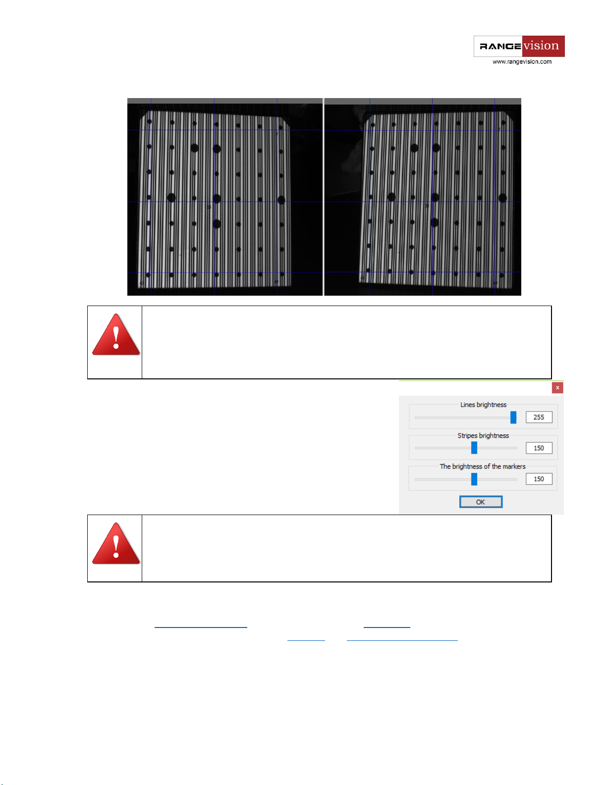
If you are setting up the 4th scanning area, it may be necessary to
decrease the brightness of lines and stripes due to the close distance
to object. In the menu Brightness setup decrease the brightness value,
as shown in the figure. Brightness value of lines is approximately 2
times greater than the brightness of the stripes. Visually lines and
stripes must be the same brightness.
Upon completion of all scanner adjustments, you should fulfil the following conditions:
● Cameras are pointed to one point, located at a distance D from the scanner
● At the same distance focused cameras and image from the projector
● At the standard values of electronic exposure (30-60) image from the cameras is not
excessively bright and not too dark
● All the adjustment and the clamping screws are tightened
28

Scanner Setup Wizard
The above actions on scanner setup can be completed by following the prompts of setup wizard in
RangeVision ScanCenter menu.
Run the setup wizard, select scanning zone, to which you need to set up the scanner, and carefully read the
description for each item in the wizard.
29

Calibrating the scanner
You need to perform calibration in order to ensure the work of the scanner after the adjustment of lenses.
Specifically for this purpose we use the calibration plate, which pre-measured with high accuracy. Scanning
software analyses the image of the plate, obtained from the cameras and compares it with the mathematical
model, marked by the algorithm.
There are 3 types of calibration: Full calibration, Orientation (short calibration) and Calibration of turn table
(finding the table axis).
Full calibration is used if:
● The lenses of the cameras need to be reconfigured (for example, if you change the scanning
area)
● If you suspect that scanning accuracy got worse
● After transporting the scanning complex
Orientation is used:
● If you suspect that the camera moved due to unreliable mounting
● If you want to check the accuracy of performed calibration
● Before the work with the scanner (recommended)
Calibration of rotary table is performed:
● In case of any change in the position of the rotary table to the scanner (when scanning on the
rotary table)
Calibration of rotary table is described in the section Scanning on rotary table.
Calibration plate
Calibration plate is a special plate with the marks, the distance between which is measured with high
accuracy. It is used for setting up a scanner and its calibration.
For each scanning zone (except №0) a separate calibration plate is used. There are only four standard
plates: №1 is the largest and №4 is the smallest. The approximate size of plates is specified in paragraph
Scanner setup.
For calibration of rotary table on the 4th scan area you should use the field "Evaluate rotation axis". On
the photo below you can see all calibration plates.
30

Calibration plate
b
№1
0.01
№2
0.007
№3
0.003
№4
0.002
Besides distance between marks on the plate each table contains measurement temperature. If the
temperature at which the calibration and scanning occurs, is very different from the specified, it is
necessary to amend the formula: ∆L=L+b*Co
∆L - change of the size of calibration plate
L - the size of calibration plate
Сo - change in the temperature in relation to the one during calibration
b - constant change in the size of the field if a temperature changes on 1oC
31

Mounting constructions
Special stands are used in order to facilitate the calibration process and fix the calibration plates.
For plates №1 and №2 is used the construction S1 , for plates №3 and №4 - S2.
32

Caution!
During and after the calibration process you should not regulate camera lenses.
After the change of the plate position it is desirable to wait for a few seconds before pressing
the Capture button to reduce the effect of external disturbances.
Note
Calibration should be performed in the same light, in which an object will be scanned. If
there is too much change of level in lighting conditions it is necessary to recalibrate the
system. It is not allowed to carry the calibration procedure on direct sunlight.
Note
During calibration it is desirable to refocus the projector.
To defocus a projector it is easier to use the zoom ring instead of the focus ring. For Acer
projectors move zoom ring from one extreme position to the other, and the projector will
be defocused; return it to the original position after calibration.
Caution!
Check that the size of the plate, specified in the software, matches the one you use. If your
plate is not in the list, see the process of adding new plates in this manual.
Full calibration
Full calibration dialog box is invoked from the menu Settings → Full calibration.
Calibration procedure:
● In the dropdown list choose the calibration plate in use. Focal distance of the lenses is
detected automatically when the field is selected from the list.
● In accordance with the text prompt and symbol image install the calibration plate in the
desired position. The brightness of the images of calibration plate can be adjusted with
exposure controller. You should not allow very dark images or images with excessive
brightness areas. Press the Capture button. Original plate position - the position at the
working distance from the scanner (marking on the view from cameras matches the markers
on the plate), the cross is projected on the central marker.
In case if not all marks are found on the image, you will see the error message.
It may mean the following:
● Not all markers are visible on one of the snapshots
● Not all markers are lit by the projector
● Calibration plate is mounted at large angle to the scanner
● Plate is too close or too far from the scanner - the image is not sharp
33

Note
Calibration is carried by the results of 11 snapshots.
Carefully observe the position of the plate during each capture!
In some positions it will be needed to rotate the plate.
● The plate is damaged or dirty
Please correct all deficiencies and press Capture .
After all the necessary snapshots are taken, calibration module will start automatically. Resulting accuracy
of calibration is specified in the last line in pixels. A good result is resulting accuracy no worse than 0.05 pix
without the use of filters and 0.08 pix when you use blue light filters.
Memorize the initial accuracy value during calibration. Working with the scanner don't forget to once in a
while perform orientation - it also serves as an accuracy indicator. If the accuracy during orienting starts to
be very different from the original one, you need to re-calibrate the equipment.
Some advice on calibration:
● Do not change the distance from the center of the plate to the scanner when turning the
plate. The exception are only snapshots in positions 10 and 11.
● Do not rotate the plate at a very high angle. Ensure that all marks on the plate are visible from
both cameras, when you turn the table.
● Be careful with calibration plates! It is not permitted to contaminate or perform any
mechanical damage to the surface with the marks. After the use store the plates in designated
case.
34

Caution!
When scanning large objects (like a car) and moving the scanner frequently, the scanner
eventually may report that it cannot find markers. In such case you need to perform
orientation.
Note
Orientation is carried by the results of 3 snapshots.
Orientation is done with the same conditions as the last calibration. The corresponding
controls in the dialog are disabled.
Caution!
After calibration or orientation, the calibration plate should be removed in order to avoid
the damage or contamination!
● Before the calibration procedure ensure that cameras and cables are secure in the designated
position.
Orientation
The orientation is started by the Adjustment → Short calibration command.
● Mount the calibration plate at the central position in the
distance D to the scanner (the first calibration position).
● Press the Capture button.
● Next, following the steps, make two more shots.
● After this the console appears and in the last line it will contain
the accuracy of orientation. It should be approximately equal
to the accuracy value of the last calibration.
If the accuracy during orienting starts to be very different from the
original one, you need to re-calibrate the equipment.
Example: The initial accuracy is 0.024 , accuracy after orientation is
0.065 . The value exceeded 0.05, re-calibration is required.
35

Scanning area
To ensure the quality of the model, the scanner clips it by the
scanning area (the yellow region on the figure below). Scan area is
limited by close and far plane in the Z-axis (depth). Scanning area is set
in the options. Scanner → Options.
The optimal depth of scan area is approximately equal to the size of
calibration plate on the selected scan area: Lзс=D
For example, for scanning area №2 D
Near-end -D
Far-end -D
/2 = - 118 mm
1-49
/2 = - 118 mm
1-49
= 236 mm
1-49
1-49
Specify these values in the settings of plane clipping.
Adding new plates
In the menu Service → Full calibration press the Edit plates (see figure below). In the resulting window,
click the Add button.
Opens the "Change the plate parameters".
The cell 1 contains digital value, which has been recorded in the back of the calibration plate. Check the
correctness of data input, this will directly affect the accuracy of the scanner! The cell 2 contains arbitrary
name of the field.
36

For editing, select the field you want to change and click Edit. To delete the unnecessary field press the
Delete button.
If you have accidentally damaged the plate and can not carry a calibration procedure, you need to order a
new one from the manufacturer.
Calibration for scanning zone №0
To obtain a three-dimensional model of large objects, RаngeVisiоn 3D scanner can be optionally equipped
with a scanning zone №0 with the scanning area 850x530x530 mm.
This scan area can be used only if there is already a scanning zone №1. To configure the scanning zone
№0:
Install lenses with focal length of 9 mm and Blue light filters on the cameras.
Perform calibration for the scanning zone №1, by specifying used 9mm lenses in the menu of full
calibration . Working distance to the field will be about 70 cm.
By loosening the By loosening the mounting, extend camera at the maximum possible distance
(about 35 cm).
Install calibration plate for the zone №1 at a distance of 105cm from the cameras.
Point the cameras at a single point, switching the Cross lighting mode and tighten the mounting.
Perform Orienting
37

Scanning
Requirements for the scanned object
The scanner analyses structured light reflected from the surface of the object, therefore, scanning should
be carried out in premises without direct sunlight, as well as free of dust and vibration. For the same reason
scanning of the following objects is not possible or is too difficult.
● too black and dark objects
● transparent objects
● mirrors
● flecking and glossy objects
● deep fur
To work with such objects it is recommended to process them with special aerosol products prior scanning,
which leave a very thin coat of white powder on the object after drying.
● HELLING Developer solution U89
● Sherwin D-100
● Developer solution ПС-33
There are also some difficulties when you are scanning objects with sharp edges, deep grooves or holes,
thin wall objects. Problems can also be caused by objects that contain large contrast areas (for example, black
lettering on white paper). Geometrical distortion may appear in places with strong contrast.
Scanning principle and methods
If you're shooting a single fragment (scan) - you get a three-dimensional model of the object surface. To
create a full object model you need to obtain surfaces of the object, that together entirety replicate the form
of the object, i.e. scan the object from different angles.
Obtained fragments are combined in the special software by the surface geometry, hence there is another
requirement - the object must be rigid and do not change its shape during the entire scanning procedure.
Otherwise, the geometry of the same area of the object surface may be different, and it will be impossible to
unite the pieces into a coherent whole.
In RangeVision 3D scanner there are 3 scan options available, which are different, in the first place, by the
fragment alignment method:
● Scanning without markers
● Scanning with markers (marks)
● Scanning on the rotary table
38

Note
When you choose the path where you want to save the project, consider a large volume of
scan data.
Each scanning options is described separately in the relevant chapter in this manual.
Creating a new project
To create a new project, click the menu and select the desired type of project:
Project without markers
Project with markers
Project on the rotary table
Specify the location where you want to save the project and scan data.
If you have created a project with markers, the Markers dialogue box with a choice of colors appears; it is
described in more detail in chapter Scanning with markers.
Determining the correct distance to object
Set an object in front of the scanner, so that the object is fixed and does not move during scanning.
Locate the correct distance to object, using the projected cross. If the cross matches with the blue markings
on the cameras - it means you have selected the correct distance (see fig. below).
39

Caution!
When setting up, carrying or calibration it is not recommended to grab the front profile of
the scanner, where the cameras are installed. A small change of position can lead to
incorrect orientation.
Caution!
Red color marks the areas of excess lighting. The scanner doesn't digitize such areas.
Adjustment is performed only by software! Do not touch Iris ring on the lensed, this will lead
to decalibration.
If the object does not fit entirely into the scan area, you should not move the scanner further. Scan the
object in a few positions, for example, the top and the bottom parts separately, and then unite these parts,
or set the scanner for a larger scanning zone.
Setting exposure of the cameras
After you place an object at the needed distance, switch the projector to the Lines and Stripes lighting
mode. Adjusting exposure of the cameras (the slider in the toolbar), get maximum exposure value, which
does not cause red dots to appear on the lines. Areas of the image, not relating to the scanned object, don't
matter.
40

Caution!
Before starting the scanning process, ensure that the object is located at the right distance
from the scanner! Distance is defined by the "Cross" illumination mode.
Action
Tool
Rotation of the model
Left mouse button
Rotation of the model in the plane of the
screen
Left mouse button on the edges of the view
Zooming/Deleting
Middle mouse button (press mouse wheel)
Dragging the model in the plane of the screen
Right mouse button
Starting and stopping the scanning process
You can launch scanning by pressing the button Start scanning on the top toolbar. You can stop it by
pressing the Stop button. Buttons will be disabled, if the scanner is not connected. To start and stop scanning
you can use hot key Space bar.
Viewing the model
To see the whole preview model you can rotate, zoom and pan the 3D view. As long as computer resources
allow it, the model is displayed in the original quality, without simplification. When loading a project with a
large amount of data visualization of the model can be simplified. To view received model select the 3D model
mode, Right or left camera mode.
You can simplify preview for decreasing time of redraw model. You can do this in the Preview options
menu.
For this drag the slide control change the degree of model simplification from 0 to 10:
41

• 0 not a simplified model
• 10 the most simplified model
The model will be recalculated in accordance with the new settings.
Unwanted noise on the 3D model
During a scanning process you may face the appearance of unwanted noise or artefacts on the model
surface. Some of the sources and means to eliminate them are listed below.
The main reason for noise appearance are vibration, and impact of external lighting. At the calibration
during shooting with the scanner both scanner and the object must be fixed relative to each other!
To reduce the impact of external lighting on the quality of models obtained by RаngeVisiоn 3D scanner,
we introduce the technology of deep illumination (Blue Light). On lenses you should install special light filters,
which allow only the blue light, projected by the scanner. This allows to carry out scanning procedures in
bright lighting conditions.
1. Waves of fluorescent lights
You can notice this effect not only on the model but on the camera views also. Thus adjust the
exposure to compensate it.
2. Excess exposure value.
If the exposure value is too high, deficiencies of camera matrix become more noticeable.
Do not use too high exposure values. If an object is too dark, and at small exposure values it is not covered
with light, recalibrate the scanner, open aperture wider.
3. Flickering of DLP projector
If the hardware settings contain a wrong projector type (DLP or LCD), then the flickering of a DLP projector
will affect the model, especially at small exposure values. On a model this is represented by striped pattern.
42

Incorrect setting up the projector, when structured light created by the software is modified by algorithms
of image improving, embedded in the projector algorithms - this also has a negative impact on the quality of
the model. You need to turn them off.
Scanning without markers
During this scan mode no additional tools are used, but the obtained fragments are not joined, and their
alignment requires more time for the processing of the scan data.
This method is used to scan items, for which you cannot affix markers or move, for example, museum
pieces.
To do this you need the following:
● Prepare the object (if necessary)
● Run ScanCenter
● Create a new project without markers or open an existing one
● Use the cross to determine the correct distance to object
● Set the camera exposure by turning on the mode of Lines and stripes
● Start scanning
If the scan is unsuccessful - select it in the tree and delete by pressing the Delete button.
Place an object or the scanner in a different position and scan the next fragment. Thus scan the desired
areas of the surface. As you finished, go to the SсаnMerge for further registration and processing the model.
Scanning with markers
This scanning method is more convenient than scanning
without markers. It is the mode the object or supporting
surface is covered with special round marks (markers).
In addition to construction of the object surface, in this
mode the scanner finds marks, determines size and
calculates their coordinates. The size of markers is specified
when creating a new project, or in the Options. If each of
the following scans has enough related marks from
previous ones, new fragment automatically will be placed
in the desired position. In this way, all the pieces will
automatically form a three-dimensional object model,
making it easier for further processing of the scan data,
speeding up the process of obtaining a 3D model.
Found marks form a reference grid. You can create a reference grid of markers in advance, and then scan
43

the object. Thus each scan will be connected to the reference grid, and not to the previous scan, without the
need for overlap between them. From this it should be noted that you can stick fewer markers to an object.
Reference grid can be used repeatedly, if you're using auxiliary object for your scanning process (for
example, plate with markers). Reference grid can be uploaded in
different formats: bаsegrid, оbс, txt from third-party sources, for
example, from photogrammetric system, that allows you to scan
large objects (for example, vehicles) without significant loss in
accuracy.
When sticking markers to an object it is desirable to choose flat
areas. In this case, on obtained model you can cut the section with
the mark, and cover the blank space without significant losses in a
result.
Using a dark surface, which is "invisible" for the scanner,
simplifies removing extra fragments when processing the model.
An example of auxiliary surface - plate with markers.
44
Caution!
Markers should be attached as chaotic as possible. Avoid expressed patterns or curves, as
this may provoke incorrect detection of markers.
When using auxiliary surface, object should not move in relation to the markers during the
scan!
Creating a reference grid
Scanning the object surface
Yellow
Marker found only once (not reliable)
Green
Marker found on several scans (reliable)
Red
Marker of the reference grid
Note
If there are not enough markers on the new scan (less than three) or the software is unable
to joint scan to already existing markers, an error message is sent and the scan is considered
to be unsuccessful.
Scanning procedure:
● Stick markers on the object or auxiliary surface
● Prepare the object to be scanned (if needed)
● Create new project with markers, specifying its size or open an existing one
● If the reference grid of 3D-marks is already created - load it through File → Load reference
● Using the Cross mode determine the correct distance to object
● Adjust exposure using the slider
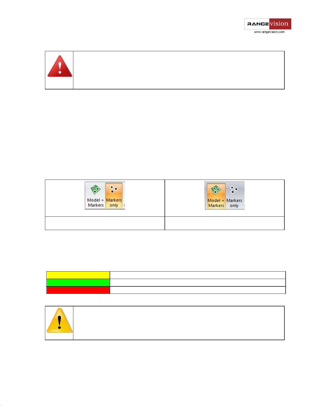
● If you are creating a reference grid, select the markers mode (left picture below) on the top
grid
toolbar. If you are scanning the object itself (with the grid or without it), select the Model
and markers mode (right picture below) on the top toolbar.
● Start scanning
● Place the object/scanner to the following position and then start the scanning process. Do
not change the position of the object regarding the marks!
● In order to view all scans, click on the title of the project.
Marker colors:
45

Caution!
When scanning large objects (like a car) and moving the scanner frequently, the scanner
eventually may report that it cannot find markers. You need to perform orientation.
Note
The optimal number of table positions - 8-12. With the increase in the number of the
possible positions, surplus amount of object fragments may also be created, which will led
to a more long processing.
● If the scan during stitching is in obviously incorrect position, it is clear that such scan should
be deleted - select it in the tree and press Delete. If you want to create the reference grid
press the File → Save reference grid.
● Scan an object from all required sides, visually observing the correct alignment of the scans
in the model view mode.
● Go to ScanMerge for further processing or create a new project to scan the object from the
other side.
Scanning on the turn table
Scanning on the turn table is performed without markers. Scanned object is installed on the platform of
the table and is automatically scanned from multiple angles.
Scanning on the turn table:
● Create new project on turn table or open an existing one
● Center the object on the platform of the table
● Place the turn table to the scanner so that during scanning the object is on the optimal
distance from the scanner.
● Configure exposure, brightness of lines and stripes, projector sharpness
● Go to Options, set the scan area clipping parameters in the field Cut cylinder, based on the
size of scanned object
● Set the number of scans per the full turn of the table in the Positions field, or specify the set
of rotation angles in angles in the Angles line.
● Remove the scanned object from the platform of the table and set a calibration plate instead.
The size of this calibration plate should be one size smaller than the one used during the
scanner calibration procedure. For calibration of turn table on the 4th scan area you should
use the field "Evaluate rotation axis".
● Measure the distance from the central marker on the plate to the table plane, record this
value in the field Height of central marker in Options.
● Press the button Define the axis of turn table in the Table calibration menu.
46

● Carefully remove the plate and put the object back on the table, not changing the position of
the scanner relative to the table
● Start scanning
● After the end of scanning go to SсаnMerge for processing
Possible problems and their solution
Settings
The cameras are turning off, I get the "Camera image acquisition fail" error
On some computers, especially on laptop computers, cameras can switch off during operation. This
happens due to the reason that cameras are powered thorough USB and may lack power. To overcome this
effect go to Adjustment → Configuration → Cameras. In the field Frequency for uEye cameras manually find
the value, at which cameras will not be switched off, or by pressing the Test button and the program itself
selects the best value (usually 18-20).
When setting up the scanner calculated distance to calibration plate does not correspond to the
distance, calculated by the formula
If the difference is several centimetres - it is not a big deal. However, if much more, check the accuracy of
installed lenses and that cameras location corresponds to the selected calibration plate by the scale. The
distance should be found from the plate. The formula is just for the validation, and not vice versa.
During the calibration procedure the scanner does not recognize markers on the calibration plate
Possible causes:
It is possible that cameras "see" other sheet with markers or other calibration plate in
addition to the one you use.
The far markers of the plate do not fall into the frame, not covered fully by the light or
covered by mounting construction
The plate is damaged, markers have defects.
Lenses are dirty
When I start the scan program cameras are not connected
Check availability and work of both cameras simultaneously in the "IDS Camera manager"
software (it is installed together with camera drivers)
Check that the correct cameras are specified in the software equipment options. Choice of
the cameras is made considering the scanner model
Try to connect cameras to other USB-ports.
At the launch of the program I see the message "Cannot write to a working directory", software settings
are not saving
47

You need to launch software as Administrator. Go to Control Panel - User Accounts - User Account Control
(UAC) and lower the slider lower down as much as possible.
Instead of letters SсаnCenter shows only signs of ?????
Go to the Control panel - Language - Additional parameters. Select English language, where this is possible.
Scanning
During the scanning procedure the scanner does not recognize markers on the object
Scanner on the images from the cameras finds all round objects, compares their size with the specified
marker diameter and calculates the coordinates of markers as a result. Therefore:
If the scanner is located at a too small angle to the surface with the marks, the marks can
look like too prickly and not round at all. Scanner will be unable to read them.
If you sprayed a cover on the model with markers, they could also been covered with spray
and became too unnoticeable. Clean the markers or place the new ones.
If the scanner decalibrated, then the calculated diameter of a marker may not match the
specified one, and markers will not be considered as such. Perform orientation or calibration. In
addition, check the size of the markers specified in Settings
There is no image of the model during the scanning process
Check operation of the scanner on the other computer! There may be a problem in the
hardware.
Check that you run the software as Administrator and there is enough disk space to record
all data
Probably there are incorrect setting for clipping the model by planes or cylinder
When scanning with markers you turned on the mode "Only markers"
There are noise and stripes on the model
Possible causes:
The noise from the light bulbs, sunlight.
Vibrations, movement of a model or a scanner.
Bad calibration or inappropriate camera settings.
The projector settings contain non-standard picture modes.
During scanning with markers the fragments are stitched wrong
Possible causes:
There is not enough marks in this area model for the normal pairing them with the reference
grid
The reference grid contains expressed figure or pattern
The model has been moved on the plate with marks.
48

The surface on the scan is "doubling".
The scanner is not calibrated
During scanning edges of the model are rough, with uneven edges.
If the light lines are parallel to the edge of the object, tilt the scanner so that the line crosses the edge at
an angle. Spray edges with matting spray.
During scanning on the rotary table scans are "shredding"
Possible causes:
The axis of rotary table is not evaluated
The position of scanner or table changed after evaluation
The scan object should be mounted in a fixed position on the area, otherwise there may be
slippage of the object when turning the table, which may lead to an error.
During scanning on the rotary table the object is missing lower part
Incorrect value of distance to the central marker: Scanner - Settings. You must set the plater for evaluation
at the rotary table, measure the distance from the table plane to the central mark on the plate and specify
the value (in mm) in Options.
49
 Loading...