

Page 1
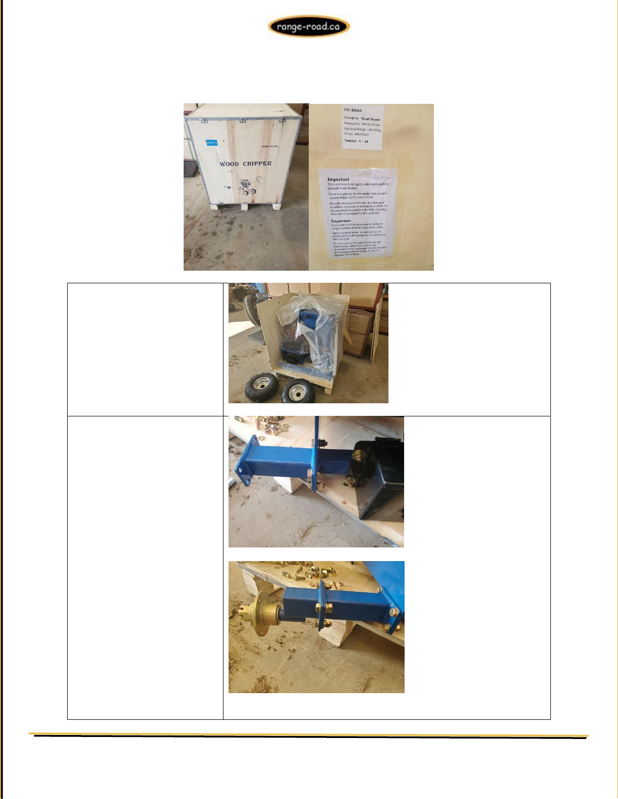
Unpack everything and start
assembly
Leave the main body assembly on
the base of the crate.
Slide the battery box to the edge
of the crate
Bolt the axle extension to the
main body assembly – 4-16mm
nuts & bolts
Bolt the axles to the axle
extensions – 4-16mm bolts & bolts
Install the wheel and tire
assembly onto both axles –
RR403 Wood Chipper
Assembly of the RR403 ATV Towable Wood Chipper.
Range Road Enterprises Ltd
Box 944
Eckville AB T0M 0X0
www.range-road.ca
Page 2
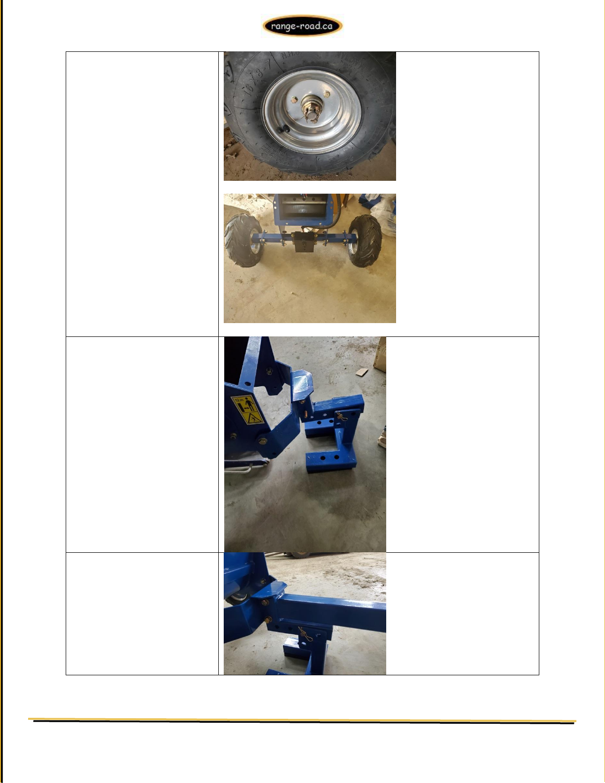
3-13mm nuts and bolts
The machine should now look like
this
Use a floor jack or blocks to
support the unit in the centre,
make sure the unit is stable then
install the front leg – 4-16mm
nuts & bolts
Install front tow bar – 2-16mm
nuts & bolts
RR403 Wood Chipper
Range Road Enterprises Ltd
Box 944
Eckville AB T0M 0X0
www.range-road.ca
Page 3
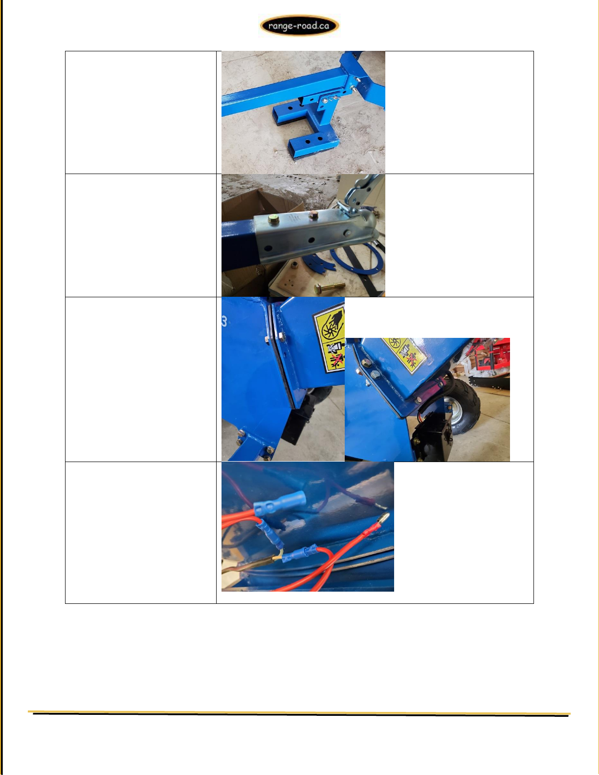
Pull out pin and install front
support leg with the feet pointing
away from the unit, put bolt
through the front hole of the leg
support and the pin & retainer
through the rear hole
Install 2” coupler – 2-16mm bolts
& nuts
Install the black rubber gasket
onto the rear of the machine and
then place the feed chute on,
install 6-16mm nuts & bolts
Connect the wire to the matching
blue connectors on engine wires
RR403 Wood Chipper
Range Road Enterprises Ltd
Box 944
Eckville AB T0M 0X0
www.range-road.ca
Page 4
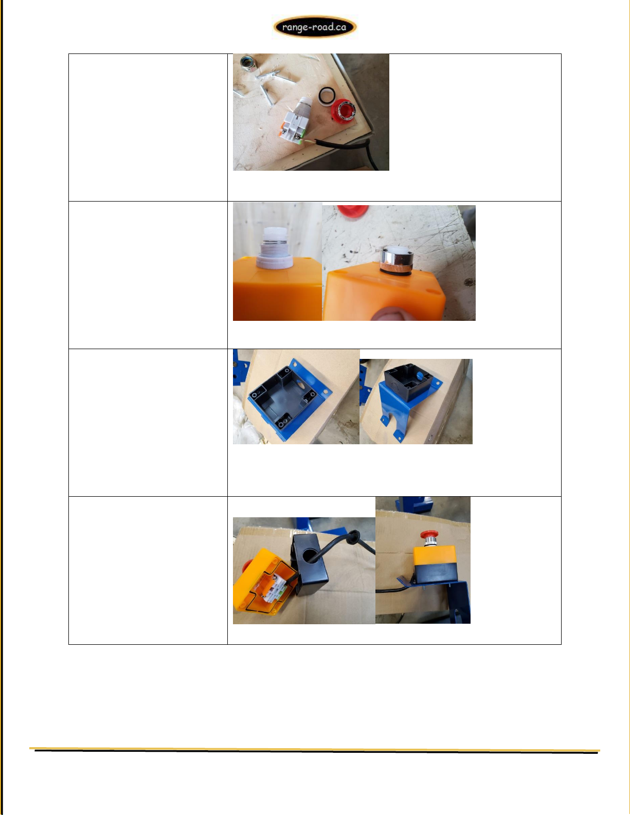
Unscrew the red emergency stop
button, the silver retainer nut
and the white retainer
If the switch goes through the
housing and 2 sizes of threads
are showing install the bigger
white nut, then the rubber seal
and chrome nut, if only 1 size of
threads come through the hole
only use the rubber seal and
chrome nut, the white nut is not
needed.
Fasten the black portion of the
switch housing to the blue mount
with the 4 provided allan head
bolts, the opening in the housing
goes above the round hole in the
mount
Make a hole in the rubber
grommet and run the wires from
the switch through the hole in
the black housing and then
through the hole in the grommet,
fasten the upper (yellow) housing
to the lower (black) housing using
the 4 screws, put the grommet in
place to seal the hole and it
should now look like the assembly
on the right
RR403 Wood Chipper
Range Road Enterprises Ltd
Box 944
Eckville AB T0M 0X0
www.range-road.ca
Page 5
Slide the wires into the metal
tube on the infeed housing, make
sure they both come through the
bottom, fasten the 4-10mm bolts
Connect these 2 wires to the
provided connectors from the
engine, red connector to red
connector, blue to blue.
Install the lower exit chute onto
the main housing, with the rubber
gasket between the 2 pieces,
tighten the 4-16mm bolts
When installing the upper chute,
1st line up the large holes for the
positioning pin on the top section,
full circular piece and on the
bottom goes the half circle.
This is usually easier to do before
mounting.
Once the holes are lined up, place
the blue flat bar, then the pin
with the spring on the top, the
blue hold down bracket goes over
top to hold everything in line, very
loosely install 2-13mm bolts &
nuts through the holes of the
hold down bracket.
Install upper chute onto lower
chute at an angle working the half
plate over the chute.
RR403 Wood Chipper
Range Road Enterprises Ltd
Box 944
Eckville AB T0M 0X0
www.range-road.ca
Page 6
Install the 2nd half circle bracket
and the rest of the 13mm bolts &
nuts, the top portion should easily
swivel when you push down on the
bar to lift the lock pin.
Tighten all the bolts & nuts and
make sure the chute still swivels
easily when you push the bar down
Snug up the bolts on the direction
flap so that it can still be moved
up and down
RR403 Wood Chipper
Range Road Enterprises Ltd
Box 944
Eckville AB T0M 0X0
www.range-road.ca
Page 7
Grease the shaft by using a
grease gun on the fittings on both
sides of the machine
Remove the outer blue cover
pictured here.
There are two Allen head bolts
that secure the drum shaft on
this side
These Allan head bolts need to be
checked for proper tension
otherwise the drum may shift
during operation
Remove the belt cover to access
the other grease fitting
While this cover is off, the 2
Allen head bolts on this side
should be checked as well.
They are located behind the
pulley but can be accessed
without pulley removal
Turn the belts by hand to ensure
the drum turns freely, adjust as
necessary
While the belts are exposed,
check the tension.
They should be tightened so the
belts have minimal deflection
(1/2” or less)
The belt tension should also be
checked on a regular basis to
ensure proper Chipper operation
RR403 Wood Chipper
Range Road Enterprises Ltd
Box 944
Eckville AB T0M 0X0
www.range-road.ca
Page 8
The machine is now fully
assembled
Add fuel and engine oil to the
engine
Check that all covers are properly
closed and the engine kill switch
is rotated and lifted up, if the
red button does not push down
turn it slightly and it will pop up
into the run position
Run the engine and verify both
the emergency kill switch and the
feed chute door kill switch
operation
RR403 Wood Chipper
Range Road Enterprises Ltd
Box 944
Eckville AB T0M 0X0
www.range-road.ca
 Loading...