

Page 1

Range Road RR20T
Firewood Processor
Crated Unit
Assembly Manual
Page 2

RR20T
Page 2
Crated Unit
1.) Undo 8 -18mm x 19mm Nuts and bolts , 2 on each leg of top frame
2.) Lift top of Metal crate off and move out of work area.
3.) Remove Shrinkwrap.
4.) Unwrap Wheels
5.) Remove bag containing Bearing, washer, nut, cotter key and cap, place
on workbench, set unwrapped wheels out of the way.
6.) Unwrap the following, place on workbench
sawdust chute
Range Road Enterprises Ltd
Box 944
Eckville AB T0M 0X0
www.range-road.ca
Page 3

RR20T
Page 3
sawbar engagement arm and extension
toolbox
fenders (2)
bar oil container, do not misplace the loose hose
towbar jack
Log roller Arm
Towbar
Splitter Wedge, Axle
Chainsaw Bar Cover, Safety Cages (2), Hydraulics Cover
The Processor should now be sitting on the crate with all loose pieces
removed
Range Road Enterprises Ltd
Box 944
Eckville AB T0M 0X0
www.range-road.ca
Page 4

RR20T
Page 4
7.) Lift processor off crate with forklift, crane or jacks, make sure that
straps will not catch anything on unit when tightened and that unit will be
balanced.
Lift high enough to be able to install Axle, Wheels and Tripod
8.) Remove lower crate from work area
9.) Install Tripod leg at front of processor
10.) Loosen Axle retention Bolts and lock nuts (18mm x 18mm)
11.) Slide Axle through tube, make sure the bolt holes face upwards,
centre the axle in the housing, tighten bolt, tighten lock nut, repeat on
opposite side
12.) Grease all 4 wheel bearings, use a flat screwdriver to remove dust
seals from hubs and remove inner wheel bearings for greasing
13.) Install Wheel on axle
Range Road Enterprises Ltd
Box 944
Eckville AB T0M 0X0
www.range-road.ca
Page 5

RR20T
Page 5
14.) Install Bearing, then washer
15.) Screw on Castle Nut make sure to line threads up
16.) Tighten castle nut until nut is snug and wheel is hard to turn, then
back the nut off ¼ turn until cotter pin hole lines up
17.) Insert cotter pin and bend
18.) Install hub cap, use a rubber mallet to press into place
19.) Grease wheel hub generously through grease zerk on back of hub
Repeat on opposite side
20.) The four lug nuts of each wheel should be torque to 90ft-lbs
.
Lower unit to floor
Assembler must check that the engine and hydraulic couplers
are secure and spaced properly
Range Road Enterprises Ltd
Box 944
Eckville AB T0M 0X0
www.range-road.ca
Page 6

RR20T
Page 6
21.) Main pump should be removed to check this.
Ensure that Lovejoy rubber is not damaged
If the crankshaft or hydraulic pump shaft sticks through the coupler to get
the right fitment, make sure that the rubber is turned so the shaft fits
into the hollow. Make sure that the keyway does not distort the rubber, if
the keyway is protruding as pictured it will damage the rubber, it must be
pushed down to be level with coupler edge
You should not see the keyway above the coupler. As shown in the picture
the keyway must be tapped down, flush with the coupler
22.) Line the Lovejoy connectors up and trial fit the pump to the motor,
adjust the lovejoys so that there is a small space in between the metal
couplers (approximately 1/16”)
23.) Tighten the bolts holding the housing to the engine and recheck the
spacing on the lovejoy
24.) Install sawdust chute 10mm Nut x Bolt through body, nuts go in the
sawdust collector side.
25.) Remove cotter pin from bottom tube on large safety cover
Range Road Enterprises Ltd
Box 944
Eckville AB T0M 0X0
www.range-road.ca
Page 7

RR20T
Page 7
26.) Remove 8 – 10mm Nuts and bolts from edge of large safety cover.
27.) Line up holes in edge of large safety cage with the holes in the side of
the chainsaw cover
28.)Install 8 – 10mm bolts and nuts, tighten
29.) Install Bar Oil Tank onto back of chainsaw safety cover with 13mm nut
30.) Remove 10mm bolt and nut from holder above splitting trough, keep
plastic tube as well
31.) Put large safety cage cover into place, slide through hole in processor
32.) Re-install 10mm Bolt, tubing and nut, snug up lock nut, do not tighten
33.) Remove nut from bar lube fitting, insert hose over barb and snug up
fitting (14mm)
Range Road Enterprises Ltd
Box 944
Eckville AB T0M 0X0
www.range-road.ca
Page 8

RR20T
Page 8
34.) Route hose through hole in cover to bar oil tank, remove nut, insert
hose over barb and snug up fitting (14mm)
35.) Remove nut from Bar Oil tank fitting, insert hose through nut and over
barb, snug up nut over hose
36.) The chain can now be adjusted to ensure the tension is set
correctly. Proper chain tension is achieved when the chain can be
pulled away from the bar by hand ¼”--‐
½”. To tighten or loosen the
chain, the two bolts can be loosened using a 12mm wrench. Next, the
allen key bolt can be turned clockwise to tighten or counter--‐
clockwise
to loosen the chain. The two 12mm bolts can be tightened again to
hold the bar securely
.
37.) Hook sawbar return spring into slot.
38.) Apply grease liberally to the metal surfaces that touch below the
spring, this will help them slide
Range Road Enterprises Ltd
Box 944
Eckville AB T0M 0X0
www.range-road.ca
Page 9

RR20T
Page 9
39.) Remove 2 10mm Nuts & Bolts and plastic tubing for small safety cover
mount
40.) Set small safety cage in place, re-install 10mm bolts nuts and tubing
41.) Bolt roller travel mount to processor, 2 – 13mm bolts and nuts (mount
may be in Toolbox)
42.) Mount toolbox, 2 – 13mm bolts and nuts
43.) Position & tighten chainsaw actuator tab so it will activate valve when
moved, can adjust later if needed
44.) Adjust bolt on swivel plate (in black circle) so that when the sawbar is
pulled down the bolt head hits the body to stop the swivel plate, this will
allow the chainsaw to cut through the log but stops it from going further
and stretching the cable.
45.) Adjust cable so that when the chainsaw bar is pulled down, the cable
will activate the ram valve, to tight and the cable will stretch, to loose and
the ram won’t activate. The cable can be adjusted at both ends.
Range Road Enterprises Ltd
Box 944
Eckville AB T0M 0X0
www.range-road.ca
Page 10

RR20T
Page 10
46.) Find the ends of the 4 Hydraulic hoses that are not hooked up
47.) Connect hydraulic hose to saw motor, make sure hose is routed cleanly
and not rubbing, connect marked Hoses to corresponding port, “A” to “A”,
“H” to “H”,etc.
Make sure all hoses are routed cleanly and will not rub
48.) Undo 17mm nuts on engine mount bolts and apply Loctite, re-tighten
49.) Remove 10mm nut, lockwasher and flatwasher from starter solenoid,
Install loop from red wire onto stud of solenoid and re-install washer and
nut, do not overtighten nut
.
50.) Remove 10mm bolt from the engine ground point, put ring from black
wire on bolt and re-install.
Range Road Enterprises Ltd
Box 944
Eckville AB T0M 0X0
www.range-road.ca
Page 11

RR20T
Page 11
51.) Tighten wires onto correct battery terminal (red +, Black-), install
terminals on battery and snug up 10mm bolts
52.) Remove 2 Allan head screws from tabs behind small safety cover
53.) Remove 10mm Bolt & nut from side of sawdust collector
54.) Remove 10mm Bolt & Nut from lower bracket by engine mount, flip
bracket outwards 180° and re-install Bolt & Nut, do not tighten
55.) Put Hydraulic cover in place (large Orange curved cover), Install 10mm
Bolt & Nut in lower hole
56.) Install 10mm Bolt & Nut in side of sawdust cover
57.) Install 2 Allan head bolts ion top of cover, tighten all bolts
Range Road Enterprises Ltd
Box 944
Eckville AB T0M 0X0
www.range-road.ca
Page 12

RR20T
Page 12
58.) Remove 2 – 13mm Bolts & Nuts from chainsaw engagement arm
extension
59.) Attach extension to drawbar and tighten 13mm bolts
60.) Remove 2 – 13mm Bolts, Nuts & Bracket from bottom of engagement
arm
61.) Put engagement arm in place, install bracket and 2 – 13mm Bolts &
Nuts, Tighten
Install Handle Extension if needed
62.) Remove 16mm bolt x 17mm nut from drawbar
63.) Slide drawbar into tube on front of processor, Re-install and tighten
16mm bolt x 17mm nut, loosen 18mm nuts on 2 retainer bolts, tighten bolts
against drawbar, then re-tighten nuts to lock into position
64.) Remove 16mm bolts x 17mm nuts from drawbar
Range Road Enterprises Ltd
Box 944
Eckville AB T0M 0X0
www.range-road.ca
Page 13

RR20T
Page 13
65.)install jack and tighten bolts
66.) Tighten bolts on drawbar coupler
67.) Remove cotter pin from fixed position roller shaft on log roll arm,
rollers are not marked so you may have to trial fit to see which roller is in
the fixed position
68.) Slide pin through both brackets and roller and re-install cotter pin.
69.) Fold log roller arm into travel position and make sure travel safety pin
slides into place, adjust mount position if necessary
70.) Mount fenders using the 2 long 13mm bolts and nuts supplied with each
fender, make sure that if the fender has signal light mounting holes they
face to the rear
repeat on opposite side
Range Road Enterprises Ltd
Box 944
Eckville AB T0M 0X0
www.range-road.ca
Page 14

RR20T
Page 14
71.) On some units the wedge adjustment lever needs to be installed by the
assembler
72.) Bolt the handle to the adjusting bar with the spring and nut in this
position, do not tighten
73.) Wedge adjustment bar swivel pin slides through tube behind the axle,
install spring clip
74.) With the handle engaged in the adjustment lock, snug up nut and bolt
so that the handle is engaged with the lock plate but it can still be pulled
out to change the wedge position
75.) Install splitter wedge
If unit was purchased without an outfeed conveyor connect unmarked loose
hydraulic hose to open port on return Tee and tighten, then proceed to step
#91.
If unit was purchased with an outfeed conveyor, DO NOT do this step
76.) Open conveyor box, remove shrinkwrap from conveyor, box includes
Conveyor Top Section
Range Road Enterprises Ltd
Box 944
Eckville AB T0M 0X0
www.range-road.ca
Page 15

RR20T
Page 15
Lower Section, includes Hydraulic pump
Top and bottom sections may already be bolted together
Belt
Top Roller
77.) Pull conveyor leg out of holders and re-intall in top tube only, place
lower conveyor in place and install 2 mount bolts, do not over tighten,
conveyor must be able to swing up and down freely
78.) Remove bolts at rear of processor body
79.) Put conveyor in place and re-install bolts, tighten
80.) Install belt, be careful when unwrapping so you don’t lose the lacing
pin. Mate the ends of the belt together to make sure as many laces overlap
each other as possible, insert pin
81.) Slide top roller into place
Range Road Enterprises Ltd
Box 944
Eckville AB T0M 0X0
www.range-road.ca
Page 16
RR20T
Page 16
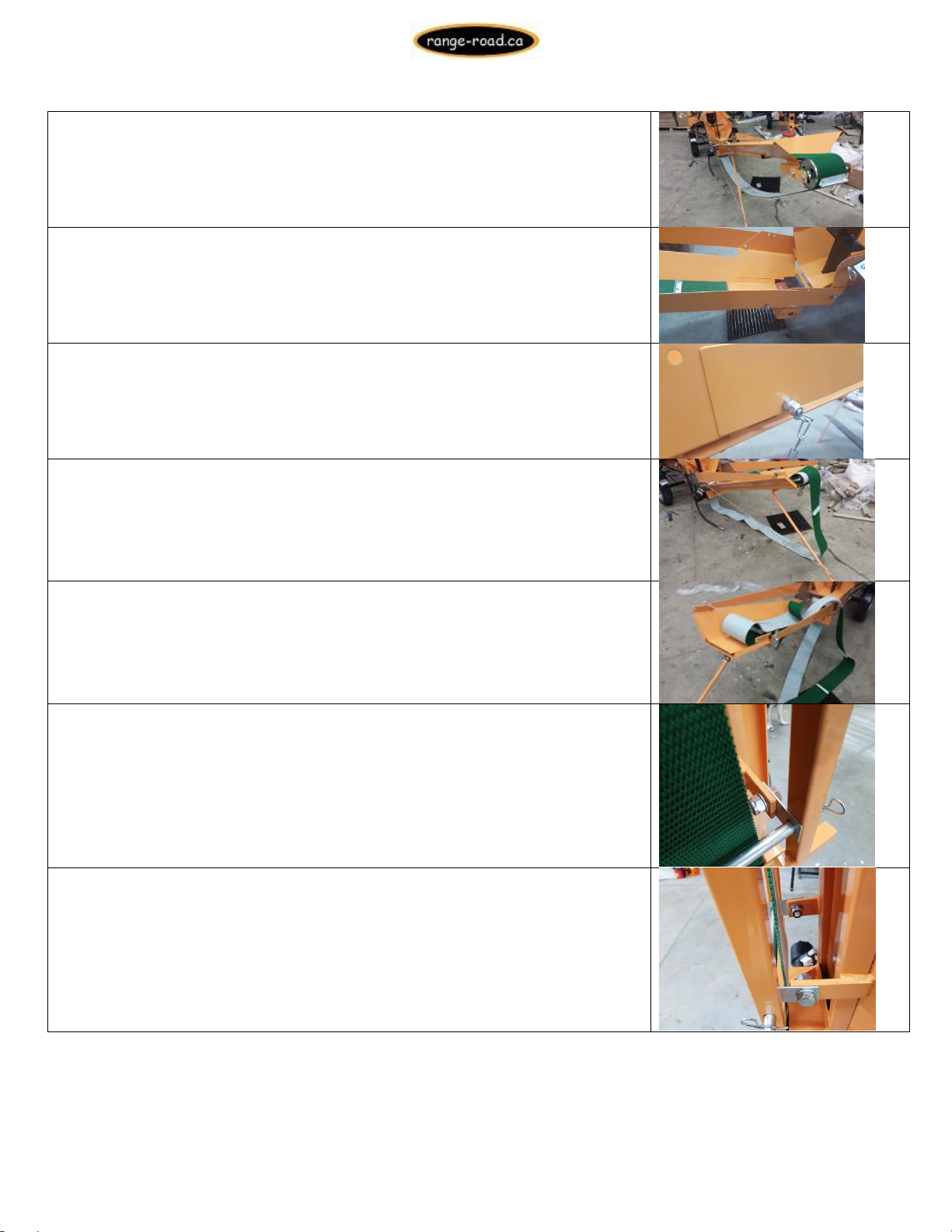
82.) Pull belt into position
83.) Install lower side extensions, lower end mounts with an allan head bolt
x17mm nut, bolt on motor side is also used to secure chain for leg
Upper end is secured with 13mm Bolts, spacers and nuts, the travel cable is
also installed with theses bolts
Some conveyors (with square leg) will have two silver plates that are used
as spacers to hold the leg away from the belt when it is in the travel
position
Range Road Enterprises Ltd
Box 944
Eckville AB T0M 0X0
www.range-road.ca
Page 17

RR20T
Page 17
84.) Hook up hydraulic hoses, one from processor to conveyor, 1 from
conveyor to processor return tee
85.) While supporting conveyor pull out safety pins and slowly lower unit,
adjust leg until conveyor is at desired height, attach safety chain to catch
at bottom of leg
86.) Unfold conveyor so that it is full length, pull pin and engage locking
clasp between upper and lower conveyor, re-insert pin
87.) Engage conveyor lock between upper and lower conveyor sections
88.) Remove travel cable from operator side of conveyor, let it hang out of
the way on opposite side
Check to make sure nuts are tight on cable clamps
89.) Turn adjusting bolts until conveyor is snug, if belt is too loose drive
pulley will spin without turning belt, if it is too tight a jammed piece of
wood could tear belt
Range Road Enterprises Ltd
Box 944
Eckville AB T0M 0X0
www.range-road.ca
Page 18

RR20T
Page 18
90.) Grease conveyor bearings, 2 at top of conveyor, 1 at bottom
91.) Check engine oil, top up or fill as necessary
92.) Add bar oil
93.) Flush hydraulic tank, pour 2-3 litres of hydraulic oil into tank, then
unscrew drain plug on bottom of hydraulic tank and drain to flush out any
contamination
94.) Make sure all return hoses are run the cleanest way, so they won’t rub
or pull tight, you may have to swap Tee’s or hose positions
95.) Add 26L AW32 hydraulic oil, in cold climates AW22 can be used and in
hot conditions AW46 can be used
96.) Check all bolts, hoses and fittings, including engine mount bolts to
make sure nothing is loose
97.) Add fuel to engine fuel tank, do not fill above red level marker in tank
neck, the tank vents through the cap, if fuel is above this line engine will
not run very well and will stall. Premium fuel is recommended, Farm Fuel
should not be used
98.) Check adjustment of chainsaw chain, remember this is a chainsaw so
the chain should not be tight, the bottom should hang off the bar slightly
Range Road Enterprises Ltd
Box 944
Eckville AB T0M 0X0
www.range-road.ca
Page 19

RR20T
Page 19
99.) Adjust safety cage hydraulic bypass valve, when the cage is closed this
valve must be completely depressed
100.) Make sure that manual ram engagement bar is in up position, Start
engine and let idle until engine and hydraulic oil are at operating
temperature
101.) While engine is warming up, adjust conveyor belt to run in center of
upper and lower pulleys, upper puller has bolts on either side for adjustment
Lower pulley only has adjustment bolts on side opposite of drive motor
When adjusted properly belt rides in center of lower pulley
102.) When unit is up to operating temperature operate saw and ram
multiple times to make sure they are adjusted and working properly
103.) Shut unit off
104.) Check all nuts, bolts, hose and fittings one more time, check for
leaks
Ram Hood Adjustment
The 2 brackets on the ram hood must be checked for adjustment to make
sure the ram does not extend to far and that when it returns it does not
have a hard hitting stop.
The rear bracket hits the manual ram bar as the rams goes out, it needs to
be adjusted so that it hits the return bar before the ram is fully extended.
Range Road Enterprises Ltd
Box 944
Eckville AB T0M 0X0
www.range-road.ca
Page 20

RR20T
Page 20
Optional: If the customer is only cutting and splitting shorter lengths, the
bar can be reversed to shorten the stroke and reduce the cycle time
The front bracket hits the post on the manual return arm as the ram
returns home, this must hit the post before the ram hits its internal
stops, softening the stop.
This should be adjusted so that the ram hood does not stick out into the
splitting valley when it is in the home position, it should not be sunk into the
housing, it should sit almost flush will the front wall.
Range Road Enterprises Ltd
Box 944
Eckville AB T0M 0X0
www.range-road.ca
Page 21

Page 21
RR20T
Range Road Equipment (Except Pellet Machines & Hammer Mills)
This equipment comes with a 12 month warranty against Manufacturer’s defects and excludes
wear parts. If any product or part is proved to be defective within 12 months from date of
purchase, by reason of improper workmanship and/or material we will replace, or repair at Range
Road Enterprises Ltd. discretion, that part or product at no charge to you, excluding any
freight costs. Pellet Makers & Hammer Mills come with a 6 month warranty against
Manufacturer’s defects and excludes wear parts.
Items not covered:
Wear parts –including Saw Bar, Saw Chain, Drive Sprocket, Lovejoy Coupling & Rubbers, Tires, Bearings, Etc.
(Conveyor Belt – does not include rips or tears)
The engine is warranted separately by the engine manufacturer (Honda, Lifan, Kohler, Princess
Auto, Ducar, Etc.)
The warranty begins on the date of sale and is warranted by Range Road Enterprises Ltd. to the original purchaser
only. This Warranty does not cover items that have been damaged by accident, alteration, abuse or improper
lubrication.
If the equipment is used commercially (Over 50 cords of firewood per year for processor) or a rental, warranty
for this product is limited to a period of 90 days from the date of purchase.
Warranty cancellation
Unauthorized modification voids the warranty, Including but not limited to, welding, engine modification, pump and
hydraulic system modification. The warranty is void if the user violates the assembly and/or operating &
maintenance instructions.
Range Road Enterprises Ltd. shall not be liable under any circumstances for any incidental or
consequential damages or expenses of any kind, including but not limited to – the cost of equipment
rental, loss of profits, or cost of hiring services to perform tasks normally performed by the equipment.
Range Road Enterprises Ltd. obligation under this warranty shall be exclusively limited to repairing or
replacing (at Range Road Enterprises Ltd. discretion) products which are determined by Range Road
Enterprises Ltd. to be defective upon delivery F.O.B. (return freight paid by customer) Range Road
Enterprises Ltd., and on inspection by Range Road Enterprises Ltd.. This warranty does not apply to
defects due, directly or indirectly, to misuse, abuse, negligence, accidents, unauthorized repairs,
alterations, lack of maintenance, acts of nature, or items that would normally be consumed or require
replacement due to normal wear. In no event shall Range Road be liable for death, personal or property
injury, or damages arising from the use of its products. Range Road Enterprises Ltd. does not issue
credits or refunds on products purchased directly from a distributor or dealer.
Range Road Enterprises Ltd
Box 944
Eckville AB T0M 0X0
www.range-road.ca
 Loading...