

Rangemaster RMDD4804, RMDD3604, RMDD3004EX, RMDD3604EX, RMDD4804EX Instructions Manual
®
Downdraft Ventilators
MODEL WIDTH
RMDD3004 30"
RMDD3604 36"
RMDD4804 48"
RMDD3004EX 30"
RMDD3604EX 36"
RMDD4804EX 48"
WARNING -To reduce the risk of burns or ignition of clothing by reaching across burners, the downdraft remote control MUST
be mounted in the countertop - at least 4" from the burners. See "INSTALL COOKTOP" section on page 8.
BLOWER
500 cfm interior
500 cfm interior
500 cfm interior
Models 331 H, 332H, 335, or 336 Exterior (purchase separately)
Models 331 H, 332H, 335, or 336 Exterior (purchase separately)
Models 331 H, 332H, 335, or 336 Exterior (purchase separately)
WARNING
TO REDUCE THE RiSK OF FIRE, ELECTRIC SHOCK, OR
INJURY TO PERSONS, OBSERVE THE FOLLOWING:
1. Use this unit only in the manner intended by the manufacturer.
Ifyou have questions, contact the manufacturer at the address
or telephone number in the warranty.
2. Before servicing or cleaning unit, switch power off at service
panel and lock the service disconnecting means to prevent
power from being switched on accidentally. When the service
disconnecting means cannot be locked, securely fasten a
prominent warning device, such as a tag, to the service panel.
3. Installation work and electrical wiring must be done by a
qualified person(s) in accordance with all applicable codes
and standards, including fire-rated construction codes and
standards.
4. Sufficient air is needed for proper combustion and exhausting
of gases through the flue (chimney) of fuet burning equipment
to prevent backdrafting. Follow the heating equipment
manufacturer's guideline and safety standards such as those
published bythe National Fire Protection Association (NFPA),
and the American Society for Heating, Refrigeration and Air
Conditioning Engineers (ASHRAE), and the local code au-
thorities.
5. When cutting or drilling into wall or ceiling, do not damage
electrical wiring and other hidden utilities.
6. Ducted fans must always be vented to the outdoors.
7. To reduce the risk of fire, use only metal ductwork.
8. Do not install this product with the activating switch directly
behind a burner or element. Minimum distance between the
switch and the edge of the burner should be 4 inches.
9. Loose-fitting or hanging clothing should never be worn when
operating this appliance. They may be ignited by burners/
elements on cooktop.
10.Children should not be left alone or unattended in the area
where this appliance is in use.
11. This unit must be grounded.
TO REDUCE THE RISK OF A RANGE TOP GREASE FIRE:
a) Never leave surface units unattended at high settings.
Boitovers cause smoking and greasy spitlovers that may
ignite. Heat oils slowly on tow or medium settings.
b) Always turn hood ON when cooking at high heat or when
cooking flaming foods.
c) Clean ventilating fans frequently. Grease should not be
allowed to accumulate on fan or filter.
d) Use proper pan size. Always use cookware appropriate
for the size of the surface element.
Page 1
WARNING
TO REDUCE THE RiSK OF INJURY TO PERSONS iN THE
EVENT OF A RANGE TOP GREASE FIRE, OBSERVE THE
FOLLOWINGa:
1. SMOTHER FLAMES with a close-fitting lid, cookie sheet,
or metal tray, then turn off the burner. BE CAREFUL TO
PREVENT BURNS. If the flames do not go out immedi
atety, EVACUATE AND CALL THE FIRE DEPARTMENT.
2. NEVER PICK UP A FLAMING PAN - You may be burned.
3. DO NOT USE WATER, including wet dishcloths or towels
- a violent steam explosion will result.
4. Use an extinguisher ONLY if:
A. You know you have a Class ABC extinguisher, and you
already know how to operate it.
B. The fire is small and contained in the area where it
started.
C. The fire department is being called.
D. You can fight the fire with your back to an exit.
aBased on "Kitchen Firesafety Tips" published by NFPA.
CAUTION
1. For general ventilating use only. Do not use to exhaust
hazardous or explosive materials and vapors.
2. To avoid motor bearing damage and noisy and/or unbalanced
impellers, keep drywall spray, construction dust, etc. off power
unit.
3. Clean filters and grease-laden surfaces frequently.
4. Do not repair or replace any part of this appliance unless
specifically recommended in this manual. All other servicing
should be done by a qualified technician.
5. Please read specification label on product for further informa-
tion and requirements.
NOTE"
Model RMDDRBK Remote Up/Down
Control sold separately.
INSTALLER:
Save this manual for Electrical
Inspector and Homeowner to use.
PLANNING
®
Downdraft Ventilators
Page 2
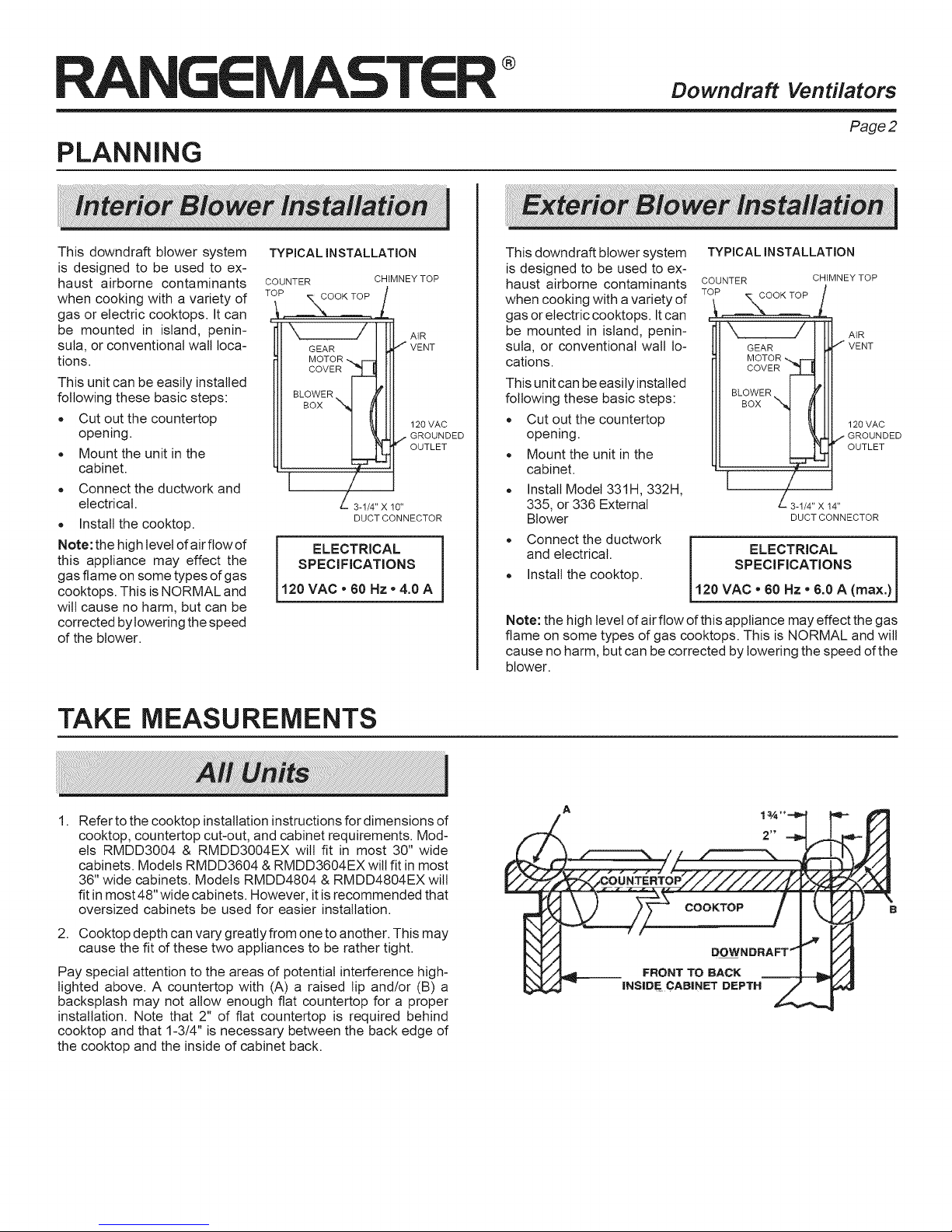
This downdraft blower system
is designed to be used to ex-
haust airborne contaminants
when cooking with a variety of
gas or electric cooktops. It can
be mounted in island, penin-
sula, or conventional wall loca-
tions.
This unit can be easily installed
following these basic steps:
• Cut out the countertop
opening.
Mount the unit in the
cabinet.
Connect the ductwork and
electrical.
Install the cooktop.
Note: the high level of air flow of
this appliance may effect the
gas flame on some types of gas
cooktops. This is NORMAL and
wilt cause no harm, but can be
corrected by lowering the speed
of the blower.
TYPICAL INSTALLATION
COUNTER CHIMNEY TOP
TOP
'e\\DO OK TOP
AtR
VENT
120 VAC
GROUNDED
OUTLET
X-1/4" X 10"
DUCT CONNECTOR
ELECTRICAL
SPECIFICATIONS
120 VAC * 60 Hz * 4.0 A
This downdraft blower system
is designed to be used to ex-
haust airborne contaminants
when cooking with avariety of
gas or electric cooktops. It can
be mounted in island, penin-
sula, or conventional wall lo-
cations.
This unit can be easily installed
following these basic steps:
Cut out the countertop
opening.
Mount the unit in the
cabinet.
,, Install Model 331H, 332H,
335, or 336 External
Blower
Connect the ductwork
and electrical.
Install the cooktop.
Note: the high level of airflow of this appliance may effect the gas
flame on some types of gas cooktops. This is NORMAL and will
cause no harm, but can be corrected by lowering the speed of the
blower.
TYPICAL INSTALLATION
COUNTER
TO _,_OOK TOP
CHIMNEY TOP
/
i
"\ f IIH.A'R
GEAR I _ VENT
MOTOR "_r"-_ fll
Jw°2 111
"I 111
I !1 II1 120VAC
i l.-'oyO 2fED
,24,,
DUCT CONNECTOR
ELECTRICAL
SPECIFICATIONS
120 VAC " 60 Hz" 6.0 A (max.)
TAKE MEASUREMENTS
1.
Refer to the cooktop installation instructions for dimensions of
cooktop, countertop cut-out, and cabinet requirements. Mod-
els RMDD3004 & RMDD3004EX wilt fit in most 30" wide
cabinets. Models RMDD3604 & RMDD3604EX will fit in most
36" wide cabinets. Models RMDD4804 & RMDD4804EX will
fit in most 48" wide cabinets. However, it is recommended that
oversized cabinets be used for easier installation.
2. Cooktop depth can vary greatly from one to another. This may
cause the fit of these two appliances to be rather tight.
Pay special attention to the areas of potential interference high-
lighted above. A countertop with (A) a raised lip and/or (B) a
backsplash may not allow enough flat countertop for a proper
installation. Note that 2" of flat countertop is required behind
cooktop and that 1-3/4" is necessary between the back edge of
the cooktop and the inside of cabinet back.
B
FRONT TO BACK
INSIDE CABINET DEPTH
®
TAKE
MEASUREMENTS (CONTINUED)
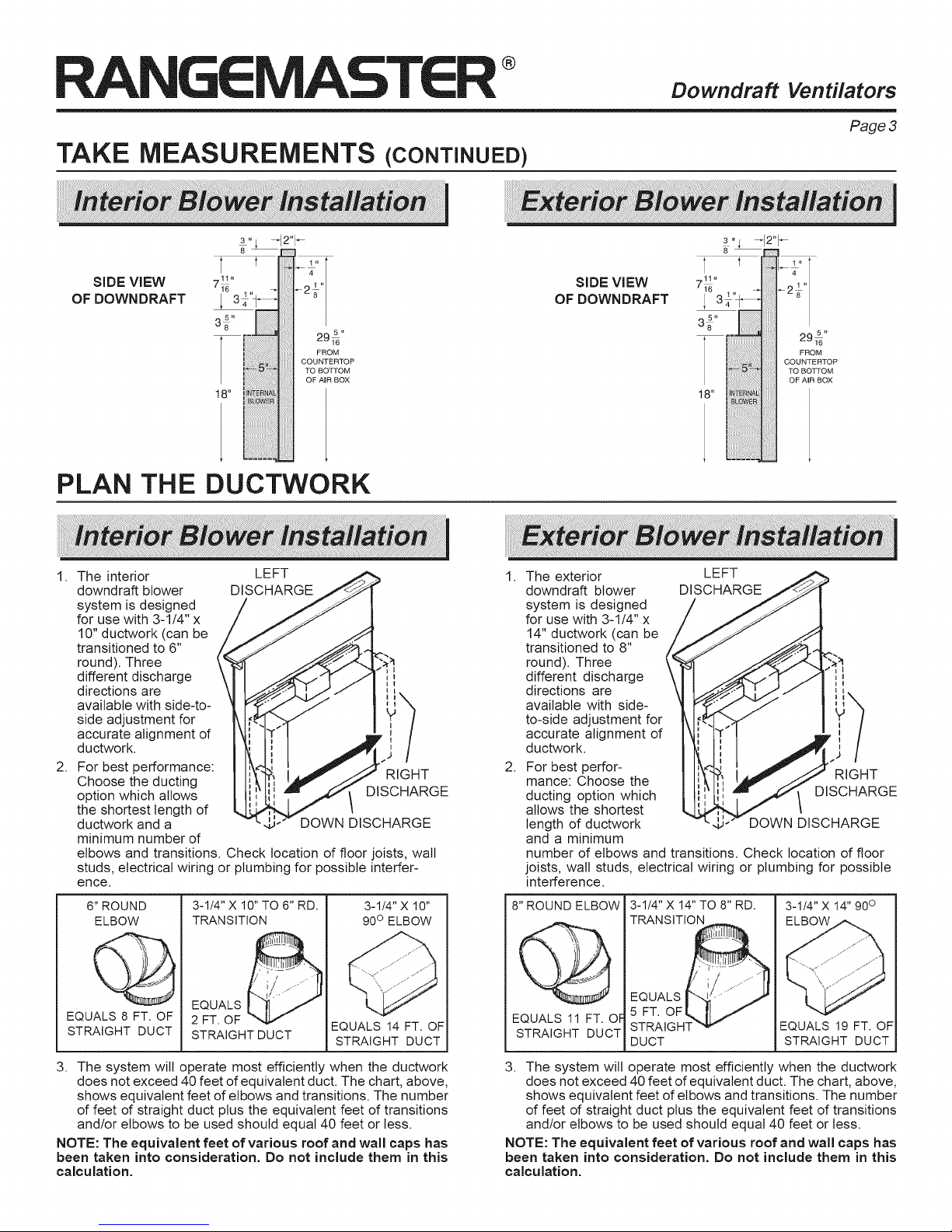
SIDE VIEW
OF DOWNDRAFT
PLAN THE
3,_ -12"1-
716 1,, _ _218 ''
FROM
COUNTERTOP
I !_ i TO BOTTOM
1 " i!iili _ _!:
2915,,
OF AIR BOX
DUCTWORK
SIDE VIEW
OF DOWNDRAFT
Downdraft
Ventilators
Page 3
295"
FROM
COUNTERTOP
TO BOTTOM
OF AIR BOX
1. The interior
downdraft blower
LEFT >
DISCHARGE
system is designed
for use with 3-1/4" x
10" ductwork (can be
transitioned to 6"
round). Three
different discharge
directions are
available with side-to-
side adjustment for
accurate alignment d
ductwork.
2,
For best performance:
Choose the ducting
'_ I_ r" JJ RIGHT
option which allows
the shortest length of
ductwork and a
J'" DOWN DISCHARGE
minimum number of
elbows and transitions. Check location of floor joists, wall
studs, electrical wiring or plumbing for possible interfer-
ence.
6" ROUND
ELBOW
EQUALS 8 FT. OF
STRAIGHT DUCT
3-1/4" X 10" TO 6" RD.
TRANSITION
EQUALS _
2 FT. OF
STRAIGHT DUCT
3-1/4" X 10"
90° ELBOW
EQUALS 14 FT. OF
STRAIGHT DUCT
1,
The exterior
downdraft blower
system is designed
LEFT .I" ,.
DISCHARGE _>_ _'
for use with 3-1/4" x
14" ductwork (can be
transitioned to 8"
round). Three
different discharge
directions are
available with side-
to-side adjustment for
accurate alignment of
ductwork.
2,
For best perfor-
mance: Choose the
ducting option which
allows the shortest
',
length of ductwork
and a minimum
number of elbows and transitions. Check location of floor
joists, wall studs, electrical wiring or plumbing for possible
interference.
8" ROUND ELBOW
EQUALS 11 FT. OF
STRAIGHT DUCT
3-1/4" X 14" TO 8" RD.
TRANSITION
DUCT
3-1/4" X 14" 90°
EQUALS 19 FT. OF
STRAIGHT DUCT
3. The system will operate most efficiently when the ductwork
does not exceed 40 feet of equivalent duct. The chart, above,
shows equivalent feet of elbows and transitions. The number
of feet d straight duct plus the equivalent feet of transitions
and/or elbows to be used should equal 40 feet or less.
NOTE: The equivalent feet of various roof and wall caps has
been taken into consideration. Do not include them in this
calculation.
3. The system will operate most efficiently when the ductwork
does not exceed 40 feet of equivalent duct. The chart, above,
shows equivalent feet of elbows and transitions. The number
of feet of straight duct plus the equivalent feet of transitions
and/or elbows to be used should equal 40 feet or tess.
NOTE: The equivalent feet of various roof and wall caps has
been taken into consideration. Do not include them in this
calculation.
®
PLAN
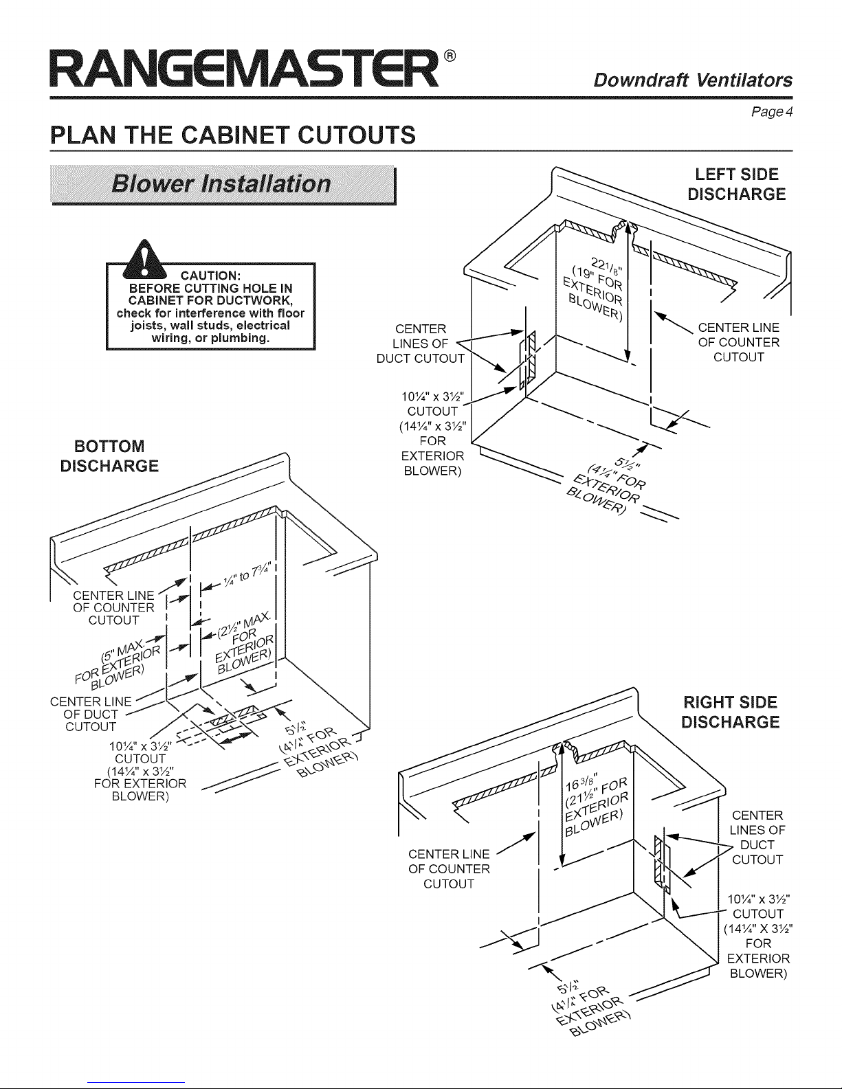
'_ CAUTION:
BOTTOM
DISCHARGE
THE CABINET CUTOUTS
BEFORE CUTTING HOLE IN
CABINET FOR DUCTWORK,
check for interference with floor
joists, wall studs, electrical
wiring, or plumbing.
CENTER
LINES OF
DUCT CUTOUT
10¼" x 3½"
CUTOUT
(14¼" x 3½"
FOR
EXTERIOR
BLOWER)
Downdraft
_...CENTER LINE
Ventilators
Page 4
LEFT SiDE
DISCHARGE
OF COUNTER
CUTOUT
OF COUNTER
CUTOUT
FO_L
CENTER LINE
OF DUCT
CUTOUT
10¼" x 3½"
CUTOUT
(14¼" x 3½"
FOR EXTERIOR
BLOWER)
CENTER LINE J
OF COUNTER
CUTOUT
j%_l j-J
RIGHT SiDE
DISCHARGE
CENTER
LINES OF
DUCT
CUTOUT
10¼" x 3½"
CUTOUT
(14¼" X 3½"
FOR
EXTERIOR
BLOWER)
®
PLAN THE WIRING
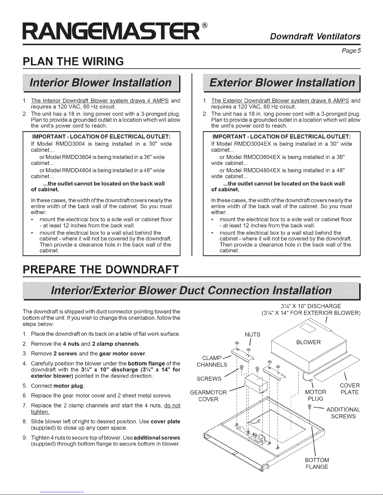
1. The Interior Downdraft Blower system draws 4 AMPS and
requires a 120 VAC, 60 Hz circuit.
2. The unit has a 18 in. tong power cord with a 3-pronged plug.
Plan to provide a grounded outlet in a location which will allow
the unit's power cord to reach.
IMPORTANT - LOCATION OF ELECTRICAL OUTLET:
If Model RMDD3004 is being installed in a 30" wide
cabinet...
or Model RMDD3604 is being installed in a 36" wide
cabinet...
or Model RMDD4804 is being installed in a 48" wide
cabinet...
...the outlet cannot be located on the back wall
of cabinet.
Inthese cases, the width of the downdraft covers nearly the
entire width of the back walt of the cabinet. So you must
either:
• mount the electrical box to a side wall or cabinet floor
- at least 12 inches from the back wall.
• mount the electrical box to a wall stud behind the
cabinet - where it will not be covered by the downdraft.
Then provide a clearance hole in the back wall of the
cabinet.
I
Downdraft
1. The Exterior Downdraft Blower system draws 6 AMPS and
requires a 120 VAC, 60 Hz circuit.
2. The unit has a 18 in. tong power cord with a 3-pronged plug.
Plan to provide a grounded outlet in a location which will allow
the unit's power cord to reach.
IMPORTANT - LOCATION OF ELECTRICAL OUTLET:
If Model RMDD3004EX is being installed in a 30" wide
cabinet...
or Model RMDD3604EX is being installed in a 36"
wide cabinet...
or Model RMDD4804EX is being installed in a 48"
wide cabinet...
...the outlet cannot be located on the back wall
of cabinet.
Inthese cases, the width of the downdraft covers nearly the
entire width of the back walt of the cabinet. So you must
either:
• mount the electrical box to a side wall or cabinet floor
- at least 12 inches from the back wall.
• mount the electrical box to a wall stud behind the
cabinet -where itwill not be covered by the downdraft.
Then provide a clearance hole in the back wall of the
cabinet.
Ventilators
Page 5
PREPARE THE DOWNDRAFT
The downdraft isshipped with duct connector pointing toward the
bottom of the unit. Ifyou wish to change this orientation, follow the
steps below:
1. Place the downdraft on its back on a table of fiat work surface.
2. Remove the 4 nuts and 2 clamp channels.
3. Remove 2 screws and the gear motor cover.
4. Carefully position the blower under the bottom flange of the
downdraft with the 3¼" x 10" discharge (3¼" x 14" for
exterior blower) pointed in the desired direction.
5. Connect motor plug.
6. Replace the gear motor cover and 2 sheet metal screws.
7. Replace the 2 clamp channels and start the 4 nuts, do not
_hten.
8. Slide blower left of right to desired position. Use cover plate
(supplied) to close up any open space.
9. Tighten 4 nuts to secure top of blower. Useadditional screws
(supplied) through bottom flange to secure bottom in blower.
CHANNELS I_
SCREWS _ I-
GEARMOTOR
COVER I ii
3¼"XI0"DISCHARGE
(3¼" X 14" FOR EXTERIOR BLOWER)
/
NUTS
\
\ COVER
MOTOR PLATE
PLUG
_ ADDITIONAL
SCREWS
BOTTOM
FLANGE
CUT COUNTERTOP OPENING
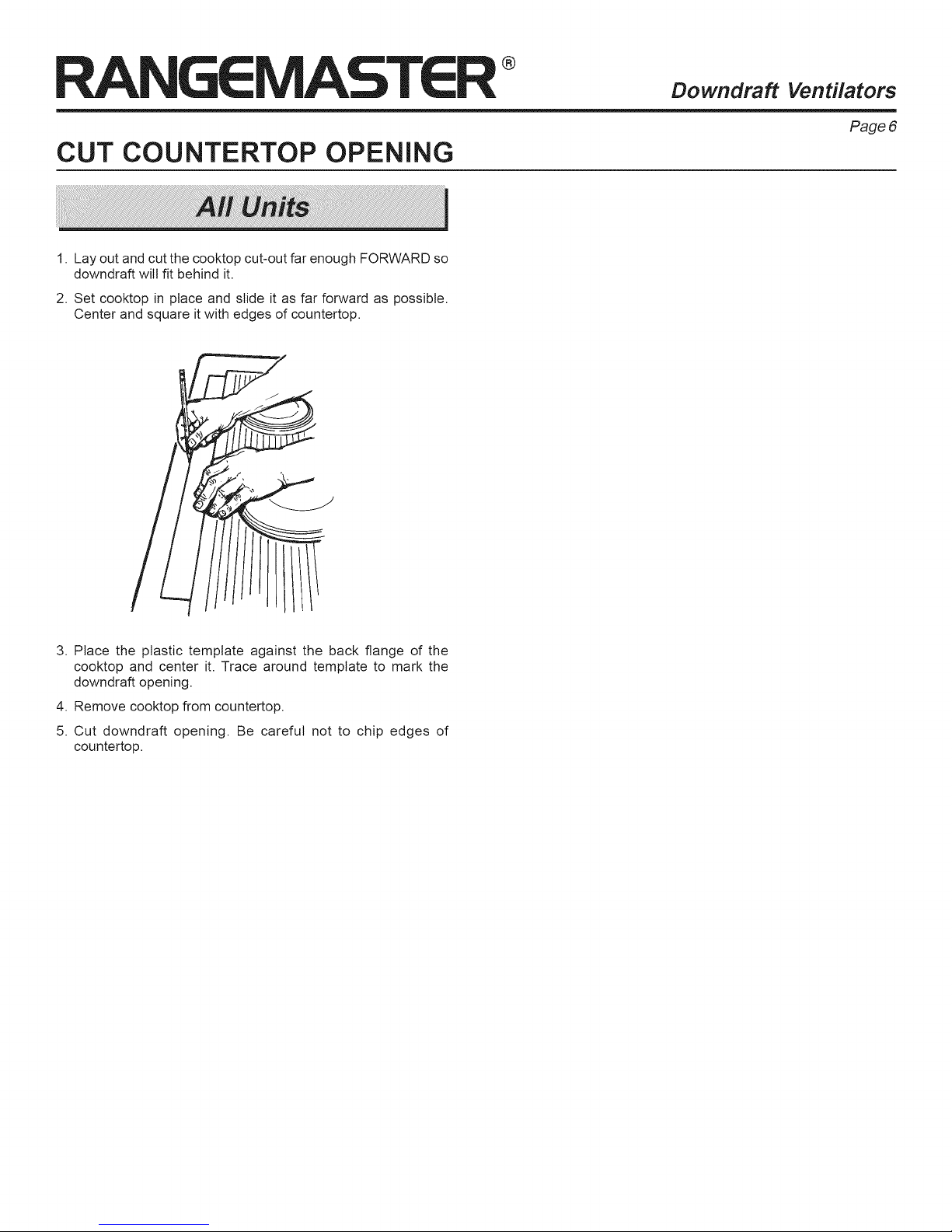
1. Lay out and cut the cooktop cut-out far enough FORWARD so
downdraft will fit behind it.
2. Set cooktop in place and slide it as far forward as possible.
Center and square it with edges of countertop.
®
Downdraft Ventilators
Page 6
3. Place the plastic template against the back flange of the
cooktop and center it. Trace around template to mark the
downdraft opening.
4. Remove cooktop from countertop.
5. Cut downdraft opening. Be careful not to chip edges of
countertop.
®
MOUNT THE UNIT
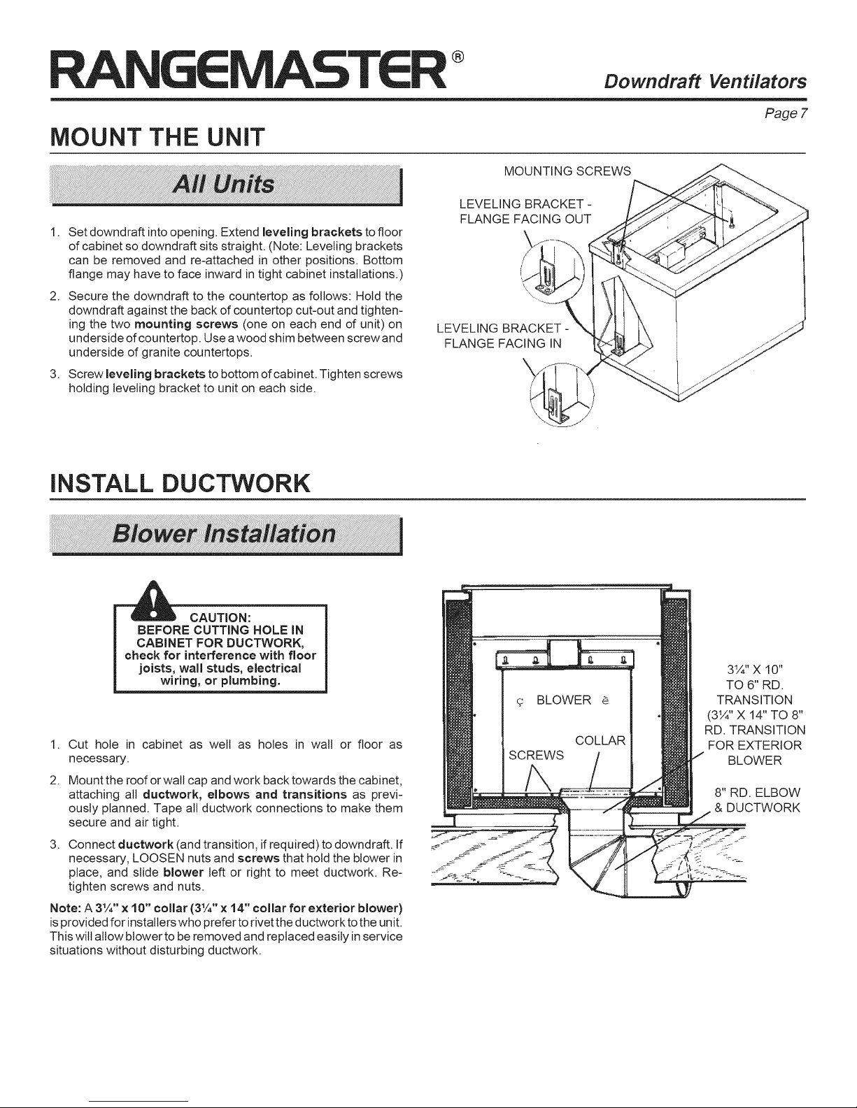
1,
Set downdraft into opening. Extend leveling brackets to floor
of cabinet so downdraft sits straight. (Note: Leveling brackets
can be removed and re-attached in other positions. Bottom
flange may have to face inward in tight cabinet installations.)
2,
Secure the downdraft to the countertop as follows: Hold the
downdraft against the back of countertop cut-out and tighten-
ing the two mounting screws (one on each end d unit) on
underside ofcountertop. Use a wood shim between screw and
underside of granite countertops.
3,
Screw leveling brackets to bottom of cabinet. Tighten screws
holding leveling bracket to unit on each side.
INSTALL DUCTWORK
MOUNTING SCREWS
LEVELING BRACKET-
FLANGE FACING OUT
LEVELING BRACKET-
FLANGE FACING IN
Downdraft
Ventilators
Page 7
--'_ CAUTION:
BEFORE CUTTING HOLE IN
CABINET FOR DUCTWORK,
check for interference with floor
joists, wall studs, electrical
wiring, or plumbing.
1. Cut hole in cabinet as welt as holes in wall or floor as
necessary.
2,
Mount the roof or wall cap and work back towards the cabinet,
attaching all ductwork, elbows and transitions as previ-
ously planned. Tape all ductwork connections to make them
secure and air tight.
3,
Connect ductwork (and transition, if required) to downdraft. If
necessary, LOOSEN nuts and screws that hold the blower in
place, and slide blower left or right to meet ductwork. Re-
tighten screws and nuts.
Note: A 3¼" x 10" collar (3¼" x 14" collar for exterior blower)
isprovided for installers who prefer to rivet the ductwork tothe unit.
This will allow blower to be removed and replaced easily in service
situations without disturbing ductwork.
3¼" X 10"
TO 6" RD.
TRANSITION
(3¼" X 14" TO 8"
RD. TRANSITION
FOR EXTERIOR
BLOWER
8" RD. ELBOW
DUCTWORK
®
iNSTALL
CAUTION: All electrical wiring should be done
by a qualified person(s) in accordance with all
applicable codes and standards.
1.
Mount a standard wiring box, with 3-pronged receptacle,
inside the cabinet. Make sure the downdraft's power cord can
easily reach it.
2.
Run appropriate power cable into cabinet and connect it to
receptacle.
3.
Plug the downdraft's power cord into the outlet. Make sure that
the power cord is routed away from the heat generated by the
cooktop.
ELECTRICAL WIRING
iNSTALL COOKTOP
Downdraft
CAUTION: All electrical wiring should be done
by a qualified person(s) in accordance with all
applicable codes and standards.
1.
Mount a standard wiring box, with 3-pronged grounded recep-
tacle, inside the kitchen cabinet. Make sure the unit's power
cord can easily reach it.
2.
Run appropriate power cabinet into cabinet and connect it to
electrical box and receptacle.
3.
Exterior blower may not exceed 6.0 Amp rating.
4.
Run 2-wire plus ground power cable from the remote blower
to wiring box on 10" round discharge plate.
5.
Connect downdraft wiring to power cable from remote blower.
Wire black to black, white to white, and green to green or bare
wire.
6.
Replace wiring box cover.
7.
Plug the downdraft's power cord into outlet. Make sure that the
power cord is routed away from the heat generated by the
cooktop.
Ventilators
Page 8
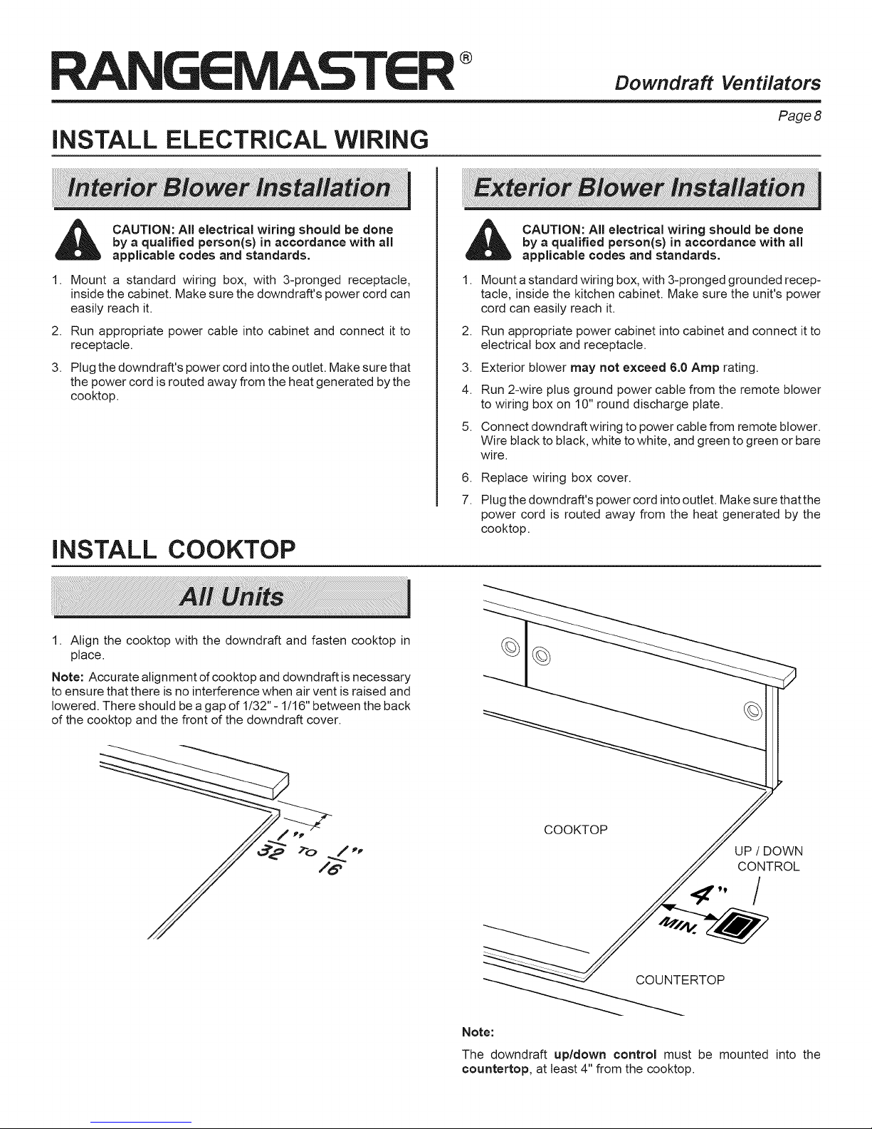
1. Align the cooktop with the downdraft and fasten cooktop in
place.
Note: Accurate alignment d cooktop and downdraft is necessary
to ensure that there is no interference when air vent is raised and
lowered. There should be a gap of 1/32"- 1/16" between the back
of the cooktop and the front of the downdraft cover.
©
©
COOKTOP
UP / DOWN
CONTROL
-X- /
COUNTERTOP
Note:
The downdraft up/down control must be mounted into the
countertop, at least 4" from the cooktop.

®
Downdraft Ventilators
Page9
REMOTE
When to use the Remote UP/DOWN Control
The Remote UP/DOWN Control should be used when your
cooktop has a burner that is within 4 inches of the UP/DOWN
Button on the downdraft chimney.
The Remote UP/DOWN Control can be used for convenient UP/
DOWN operation of the downdraft chimney (even when a burner
is more than 4 inches from the UP/DOWN Button of the downdraft
chimney).
How to use the Remote UP/DOWN Control
Do not place the remote control where it wilt interfere with
cooking, where hot pans could be set, or where hot liquids could
be spilled on the control.
The Remote UP/DOWN Control disables the UP/DOWN function
of the UP/DOWN Button on the downdraft chimney.
Installation
1. Using the template at right, lay out the 3-hole pattern on the
counter top. Mark the centers of the three holes to be drilled.
2. Carefully drill the three holes through the counter top. Be
careful not to damage or chip the counter top surface when
drilling the holes.
3. Remove the control from the plastic bag. Line the control up
with the three holes and position the control so it is parallel
with the front d the counter top.
4. Remove the two nylon thumbnuts from the plastic bag and
thread onto the two studs on the control from below the
counter top. Hand tighten only.
WARNING: To reduce the risk of burns or ignition
of clothing by reaching across burners, the re-
mote control must be mounted at least 4" away
from any cook top burner.
5. Remove the blower, clamp channels, and gearmotor cover
from downdraft (see"Prepare the Downdraft" on page 5).
Remove the large panel to expose the downdraft's wiring.
UP/DOWN CONTROL INSTALLATION (OPTIONAL)
WIRING
BOX
.438
DIA.
HOLE
2.000
.250 DIA.
HOLES
DOTTED LiNE
--f-
.750
br
I
I .750
I
WIRING
BOX
6. At the lower right hand corner of downdraft, unplug the cable
from the left side of the wiring box.
DOWNDRAFT
CABINET
FLOOR
REMOTE
CABLE
LOWER
RIGHT
SIDE
OF
7. Remove remote cable from the plastic bag and plug into back of
control from below counter top. Route cable through cabinet to
lower right hand comer of downdraft and through the clearance
holes in the side of downdraft and wiring box. Plug cable intocircuit
board plug, as shown.
8. Stuff excess cable out of the way, secure the cable so it is not
damaged by itemsstoredinthe cabinet, and reassemble downdraft.
®
USE AND CARE
WARNING: Always disconnect electric
supply before cleaning and/or servicing unit.
Always turn the downdraft blower on before you begin cooking to
establish an air flow in the kitchen. Let the blower run for a few
minutes to clean the air after you turn the cooktop off. This will
keep the whole kitchen cleaner and brighter. The activating switch
is pressed and the air vent rises.
power
Downdraft
Cleaning
Use a mild detergent suitable for painted surfaces. DO NOT USE
ABRASIVE CLOTH, STEEL WOOL PADS, OR SCOURING
POWDERS. Vacuum blower to clean. Do not immerse blower in
water.
Wash the 2 aluminum/stainless steel grease filters in a mild
detergent solution or a dishwasher, Remove them from the air
vent by grasping the tab at the top of each filter,
Servicing
It may be necessary to remove the downdraft blower system from
the cabinet in order to service components such as the blower
motor or air vent mechanism.
Disconnect power to the cooktop and remove it first. Reverse the
steps under "MOUNT THE UNIT" to remove the downdraft from
the cabinet.
Ventilators
Page 10
BACKSIDE OF
REMOTE SWITCH
TEMPLATE
OPERATION
®
Downdraft Ventilators
Page 11
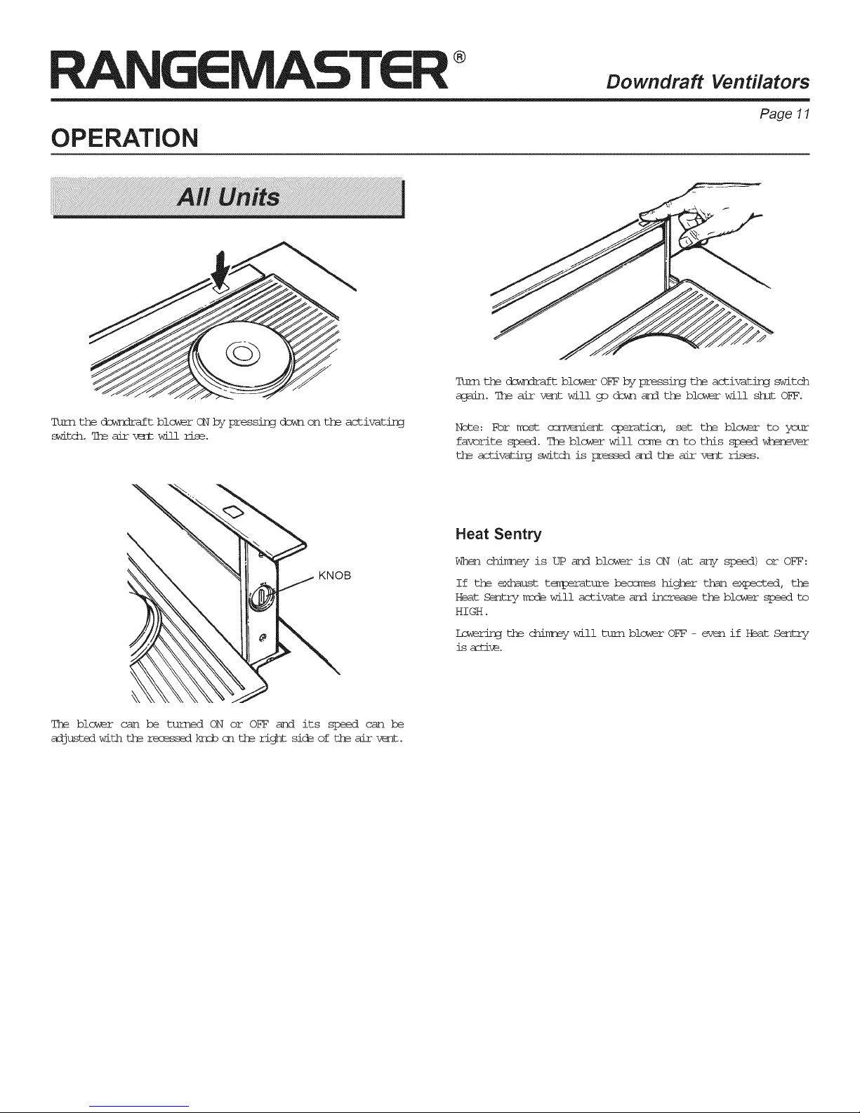
Turnthe_t bl_er OFF by pressingtheactivatingswitch
again.The air v_ntwillgo dckns_d the blowerwillsh!tOFF.
Turn the dowrlraft b!ower ON by pressing down on the activating
switch.7h_air-_ wil! rise.
KNOB
The b!ower can be turned ON or OFF and its speed can be
adjustedwithth_rec_sedkseben th_rightsic_ofth_air-w<r_t.
Note: For Kost corfqemier_cperation, set the blcwar to your
favorite speed. The blcwer wil! ccm_ cn to this slseeffwhenever
th_ activatirgswitch is pressed and th_ air vc_t rises.
Heat Sentry
When chimey is UP and blower is ON (atany speed)or OFF:
If the exhaust tem!3eratureheosm÷s higher than expected, the
Heat Sentry msde wil! activate and increase the b!ower s_ed to
HIGH.
Lc_rLngthechimc_ywil!turnbl__rOFF- evenifHeatSentry
isamid.

®
WARRANTY
BROAN ONE YEAR LIMITED WARRANTY
Broan warrants to the original consumer purchaser of
its products that such products will be free from defects
in materials or workmanship for a period of one year
from the date of original purchase. THERE ARE NO
OTHER WARRANTIES, EXPRESS OR IMPLIED, IN-
CLUDING, BUT NOT LIMITED TO, IMPLIED WARRAN-
TIES OR MERCHANT ABILITY OR FITNESS FOR A
PARTICULAR PURPOSE.
During this one-year period, Broan will, at its option,
repair or replace, without charge, any product or part
which is found to be defective under normal use and
service.
THIS WARRANTY DOES NOT EXTEND TO FLUO-
RESCENT LAMP STARTERS, TUBES, HALOGEN AND
INCANDESCENDT BULBS. This warranty does not
cover (a) normal maintenance and service or (b) any
products or parts which have been subject to misuse,
negligence, accident, improper maintenance or repair
(other than by Broan), faulty installation or installation
contrary to recommended installation instructions.
The duration of any implied warranty is limited to the
one-year period as specified for the express warranty.
Some states do not allow limitation on how long an
implied warranty lasts, so the above limitation may not
apply to you.
BROAN'S OBLIGATION TO REPAIR OR REPLACE, AT
BROAN'S OPTION, SHALL BE THE PURCHASER'S
SOLEAND EXCLUSIVE REMEDY UNDERTHIS WAR-
RANTY. BROAN SHALL NOT BE LIABLE FOR INCI-
DENTAL, CONSEQUENTIAL OR SPECIAL DAMAGES
ARISING OUT OF OR IN CONNECTION WITH PROD-
UCT USE OR PERFORMANCE.
Some states do not allow the exclusion or limitation of
incidental or consequential damages, so the above
limitation or exclusion may not apply to you.
This warranty gives you specific legal rights, and you
may also have other rights, which vary from state to
state. This warranty supersedes all prior warranties.
To qualify for warranty service, you must (a) notify Broan
at the address or telephone number below, (b) give the
model number and part identification and (c) describe
the nature of any defect in the product or part. At the time
of requesting warranty service, you must present evi-
dence of the original purchase date.
Broan-NuTone LLC, 926 W. State Street,
Hartford, Wisconsin 53027 (1-800-637-1453)
Downdraft
Ventilators
Page 12
SERVICE PARTS
KEY 30N 36N 48N
NO. WIDTH WIDTH WIDTH DESCRIPTION
1 97015987 97015988 97015989 TOP COVER
2 99140195 99140195 99140195 FILTERSPRING
3 99230345 99230345 99230345 POP RIVET
4 97015970 97015971 97015972 CHIMNEYWELDMENT
5 97015874 97015874 97015874 ENDCAP RH
6 98009358 98009358 98009358 ENDCAP LR
7 97015973 97015973 97015973 MACHINEDCHIMNEYSLIDE
8 98010013 98010013 98010013 MACHINEDAIRBOXSLIDE
9 99160421 99160421 99160421 SCREWRHM8-32x .375
10 99160419 99160419 99160419 SCREW8-32x..500PHL
11 99271218 99271218 99271218 GROUNDWIRE
12 99150471 99150471 99150471 SCREW10-32x .500TYPCAPH
13 97015841 97015842 97015843 FILTER
14 99710032 99710032 99710032 SPACER
15 99111184 99111184 99111184 SLIDE STRIPS
16 97015974 97015975 97015976 AIRBOXWELDMENT
17 99271210 99271210 99271210 CORDSET
18 99400060 99400060 99400060 STRAINRELIEFBUSHING
19 99271295 99271295 99271295 WIRE HARNESS
20 99271292 99271292 99271292 POT ASSEMBLY
21 99271291 99271291 99271291 CONTROLBOARD
22 97015674 97015674 97015674 CRANK ASSEMBLY
23 97015977 97015977 97015977 GEAR MOTORBRACKET
24 99080513 99080542 99080542 GEAR MOTOR
26 98009802 98009801 98009800 FRONTAIRBOXBOTTOM
27 97015990 97015991 97015992 GEAR MOTORCOVER
INTERNALBLOWERMODELS
97015993 97015994 97015995 GEAR MOTORCOVER
EXTERNALBLOWERMODELS
28 98008158 98008158 98008158 AIRBOX OPENINGCOVER
29 98009773 98009773 98009773 AIRBOXCLAMP
30 99260488 99260488 99260488 WHIZNUT10-24
31 97015700 97015700 97015700 SCROLLBOXASSEMBLY
32 98008150 98008150 98008150 SCROLLBOXCOVER
33 98008157 98008157 98008157 CAPACITORCLAMP
34 98008167 98008167 98008167 EXT - SCROLLBOXWELDMENT
35 99080362 99080362 99080362 MOTORW/CAPACITOR
36 99020247 99020247 99020247 BLOWERWHEEL
37 99100484 99100484 99100484 MOTORMOUNTISOLATOR
38 99260477 99260477 99260477 WHIZNUT1/4-20
39 99030323 99030323 99030323 THERMOSTAT
40 97015903 97015903 97015903 ADAPTOR PLATE
41 98010005 98010005 98010005 OUTLETPLATE
42 99271304 99271304 99271304 WIRE HARNESS
43 99400042 99400042 99400042 STRAINRELIEFBUSHING
44 99271296 99271296 99271296 UP/DOWNBUTTONHARNESS
45 99271306 99271306 99271306 THERMOSTATWIREHARNESS
46 98010010 98010010 98010010 THERMOSTATMOUNTING
BRACKET
 Loading...