

Page 1
LEIHDC70SC - LEIHDC70BB
LEIHDC70BC
Instructions Manual
www.range master.co.uk
Page 2

INDEX
RECOMMENDATIONS AND SUGGESTIONS......................................................................................................................3
CHARACTERISTICS..............................................................................................................................................................4
INSTALLATION ......................................................................................................................................................................5
USE.........................................................................................................................................................................................8
MAINTENANCE......................................................................................................................................................................9
EN
2
2
Page 3
EN
The Instructions for Us e appl y t o seve ral ve
rsions of this appli ance. Accor
d-
650 mm min.
RECOMMENDATIONS AND SUGGESTIONS
ingly, you may fin d descriptions of indi vidual features that d o not apply to
your specific appliance.
INSTALLATION
• The manufacturer will not b e held liable for any dam ages resulting fr om incorrect or i mpr op er in sta l lat ion .
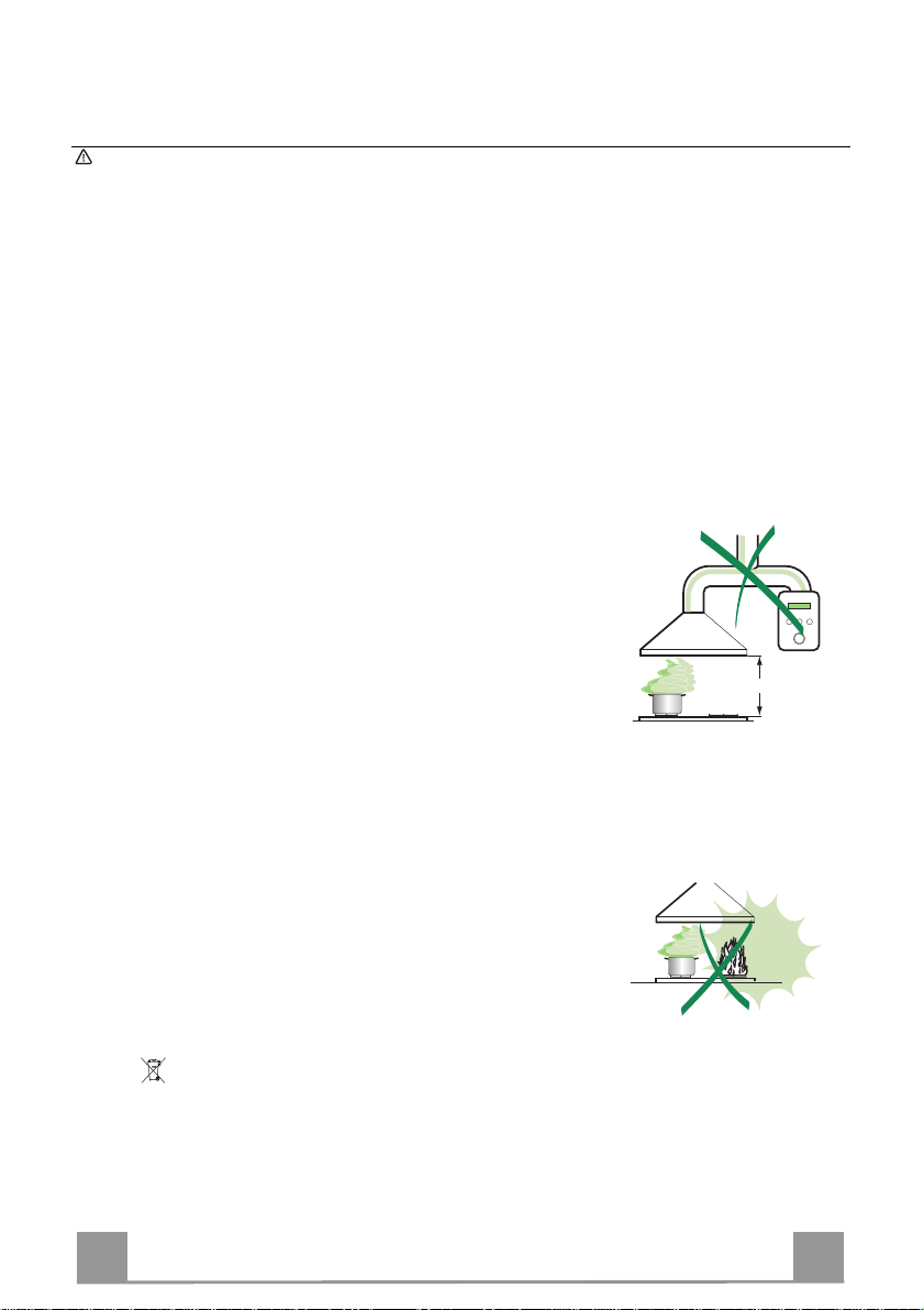
• The minimum safety distance between the cooker top and the extractor
hood is 650 mm (som e m od el s can be installed at a lower height, please refer to the paragraphs on working dimensions and installation).
• Check th at the mains voltage corres ponds to that indicated on the rating
plate fixed to the inside of the hood.
• For Class I appliances, check th at the domestic power supply guarantees
adequate earthing.
Connect the extractor t o the ex haus t flu e throu gh a pipe o f mi nimum diame-
ter 120 mm. The route of the flue must be as short as possible.
• Do not conn ect the extractor hood to exhaus t ducts carrying combustion
fumes (boilers, fireplaces, etc.).
• If the ext ra ctor is used in conjunction with non-electrical appliances (e. g. g as
burning applia nces), a suffi cient degree of aeration must be guarantee d in
the room in order to prevent t he backfl ow of exha ust gas. T he kitch en must
have an opening communicating directly with the open air in order to
guarantee the entry of clean air.
USE
• The extractor hood has been designed exclusively for domestic use to eliminate kitchen smells.
• Never use the hood for purposes other than for which it has been designed.
• Never leave high naked fla me s un der the ho od wh en it is in oper at i on.
• Adjust th e fl am e i n te nsity to direct it onto the bottom of t he pan only, making
sure that it does not engulf the sides.
• Deep fat fryers must b e continuously m onitored durin g use: overheate d oil
can burst into flames.
• Do not flambè under the range hood; risk of fire
• This appliance is not intended for use by persons (includi ng children) with
reduced physical , sensory or mental capabilitie s, or lack of ex perience and
knowledge, unless th ey have been g iven su pervi sion o r in structi on con cern ing use of the appliance by a person responsible for their safety.
• Child re n sh ould be supervised to ensure that they do not play with the appliance.
MAINTENANCE
• Switch off or unplug the appliance from the m ains supply before carrying out
any maintenance work.
• Clean and/or replace the Filters after the specified time period (Fire hazard).
• Clean the hood using a damp cloth and a neutral liquid detergent.
The symbol on the product or on its packaging indicates that this product may not be treated
as household waste. Instead it shall be handed over to the applicable collection point for the
recycling of electrical and electronic equipmen t. By ensuring this pr o duct is disposed of correctly,
you will help prevent potential negative consequences for the environment and human health,
which could otherwise be caused by inappropriate waste handling of this product. For more
detailed information about recycling of this product, please contact your local city office, your
household waste disposal service or the shop where you purchased the product.
3
3
Page 4
EN
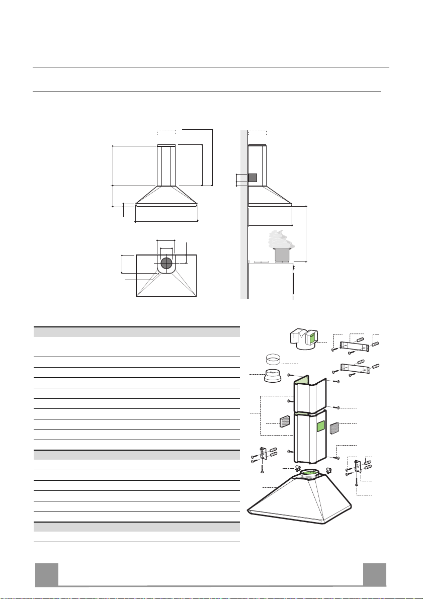
CHARACTERISTICS
Dimensions
360
240
30
200
r 58
698 - 898
190
ø150
max 760
min 560
100
Components
Ref. Q.ty Product Components
1 1 Hood Body, complete with: Controls, Light, Blower,
2 1 Telescopic Chimney comprising:
2.1 1 Upper Section
2.2 1 Lower Section
8a 1 Right Air Outlet Grill
8b 1 Left Air Outlet Grill
9 1 Reducer Flange ø 150-12 0 mm
10 1 Adapting ring ø 120-125 mm
15 1 Air Outlet Connection
17 2 Lower Chimney Fixing Bush
Ref. Q.ty Installat i on Comp o nent s
7.1 2 Hood Body Fixing Brack et s
7.2.1 2 Upper Chimney Section Fixing Brackets
11 8 Wall Plugs
12a 8 Screws 4.2 x 44,4
12c 6 Screws 2.9 x 9.5
12d 2 Screws M4 x 25
Q.ty Documentation
1 Instruction Manual
Filters
9055
492
650 min.
12a 11
7.2.1
15
2.1
2.2
1
10
12e
8b
17
8a
12e
12a
7.1
12d
11
4
4
9
2
Page 5

EN
INSTALLATION
Wall drilling and bracket fixing
7.2.1
120
7.1
120
650 min.
Wall marking:
• Draw a vertical line on the supporting wall up to the ceiling, or as high as practical, at the
centre of the area in which the hood will be installed.
• Draw a horizontal line at 650 mm above the hob for installation without the back panel, or at
height H (height of the visible part of the panel) for installation with the back panel.
• Place bracket 7.2.1 on the wall as shown about 1-2 mm from the ceiling or upper limit,
aligning the centre (notch) with the vertical reference line.
• Mark the wall at the centres of the holes in the bracket.
• Place bracket 7.2.1 on the wall as shown at X mm below the first b racket ( X = height of the
upper chimney section supplied), aligning the centre (notch) with the vertical line.
• Mark the wall at the centres of the holes in the bracket.
• Place bracket 7.1 as shown 120 mm from the vertical reference line and 175 mm abo ve the
horizontal reference line.
• Mark the centres of the holes in the bracket.
• Repeat this operation on the other side.
REAR PANEL (OPTIONAL)
The Rear Panel must be fitted before fixing the hood body and, if it is to be fixed at both top
and bottom, must be fitted at the correct height prior to installing the bases. As this operation is
rather complex, it should be carried out either by the kitchen installer or a qualified person
who knows the final dimensions of the units.
For fixing at the top only, proceed as follows:
• Rest the back pan el on t he base, i nsert ing th e lower plate b etween the upp er surface and the
wall, centring it on the vertical reference line.
• Mark the centres of the two holes in the upper plate.
• Drill ø 8 mm holes at all the centre points marked.
• Insert the wall plugs 11 in the holes.
• Fix t he brackets using the 12a screws supplied.
• Fix the back panel (where present) using the 12a screws supplied.
1÷2
X
H 175
5
5
Page 6

EN
12.d
7.1
9
ø 125
10
ø 150
15
Mounting the hood body
• Screw the two screws 12d supplied onto the brackets 7.1.
• Hook the hood body onto the bracket 7.1, centring it around
the vertical line.
• Use the adju sting screws 12d underneath the hood to level the
hood body.
Connections
DUCTED VERSION AIR EXHAUST SYSTEM
When installing the ducted version, connect the hood to the
chimney using either a flexible or rigid pipe ø 150 or 125 mm,
the choice of which is left to the installer.
• To install a ø 125 mm air exhaust connection, insert the reducer flange 9 on the hood body air outlet and the adapting
ring ø120-125 10 on the reducer flange.
• Fix the pipe in position using sufficient pipe clamps (not supplied).
• Remove any activated charcoal filters.
RECIRCULATION VERSION AIR OUTLET
• Push fit the air outlet fitting 15 onto the air outlet of the hood
body.
• Ensure that the activated charcoal filters have been inserted.
6
6
Page 7

EN
1
12e
17
8b
2.1
2.2
2
8a
7.2.1
12e
ELECTRICAL CONNECTION
• Connect the hood to the mains through a two-pole switch having a contact gap of at least 3 mm.
• Re move the grease filters (see paragraph Maintenance) being
sure that the conn ector of the feeding cable is correctly inserted
in the socket placed on th e side of the fan.
Chimney assembly
Upper chimney section
• Slightly widen the two sides of the upper chimney and hook
them behind the brackets 7.2.1, making sure that they are prop erly housed.
• Secure the sides to the brackets using the 4 screws 12e (2,9 x
9,5) supplied.
Lower ex haust flue
• Insert the lower flue fixing bush 17 in the top of the hood body
and rotate it 90° clockwise as far as it will go.
• Slightly widen the two sides of the chimney and hook them
between the upper chimney section and the wall, making sure
that they are properly housed.
• Secure the sides of the botto m section to the bushes provided
using the 2 screws 12c (2,9 x 9,5) supplied.
• On the recirculation version, fit the directional grids 8a – 8b in
their housings making sure that the directional symbols are towards the top and front of the hood. Also make sure that they
are correctly inserted in the ou tlet connection piece 15.
7
7
Page 8

EN
USE
3
2
1
0
1
0
M
L
L Light Switches the lighting system on and off
M Motor Switches the extractor motor on and off
V Speed Sets the operating speed of the extractor:
1. Low speed, used for a co ntinu ous and silent air ch ange i n the presen ce o f
light cooking vapour.
2. Medium speed, suitable for most operating conditions given the optimum
treated air flow/noise level ratio.
3. Maximum speed, used for eliminating the highest cooking vapour emission, including long periods.
1
V
8
8
Page 9

EN
A
B
MAINTENANCE
Grease filters
CLEANING META L SELF- SUPPO RTING GREASE FILTERS
• The filters must be cleaned every 2 months of operation, or
more frequently for particularly heavy usage, and can be
washed in a dishwasher.
• Remove the filters one at a time by pushing them towards the
back of the group and pulling down at the same time.
• Wash the filters, taking care not to bend them. Allow them to
dry before refitting.
• When refitting the filters, make sure that the handle is visible
on the outside.
Activated charcoal filter (Recirculation version)
These filters are not washable and cannot be regenerated, and
must be replaced approximatel y every 4 months of operati on, or
more frequently with heavy usage.
REPLACING THE ACTIVATED CHARCOAL FILTE R
• Remove the metal grease filters
• Remove the saturated activated charcoal filter as shown (A).
• Fit the new filters (B).
• Replace th e metal greas e filters.
Lighting
LIGHT REPLACEMENT
40 W incandescent light.
• Remove the metal terminals fixing the light cover.
• Slide the light cover to the right until the left hand is free.
Lower it slightly and slide it to the left to free it completely.
• Unscrew the bulb s and replace th em with new ones h aving the
same characteristics.
• Replace t he lighting support in reverse order.
9
9
Page 10

Page 11

Page 12

4329645_ver7
AGA RANGEMASTER GROUP PLC
 Loading...