

Page 1
GB
Instruction Manual
Page 2

Page 3
RECOMMENDATIONS AND SUGGESTIONS
INSTALLATION
• The manufacturer will not be held liable for any damages
resulting from incorrect or improper installation.
• The minimum safety distance between the cooker top and the
extractor hood is 650 mm.
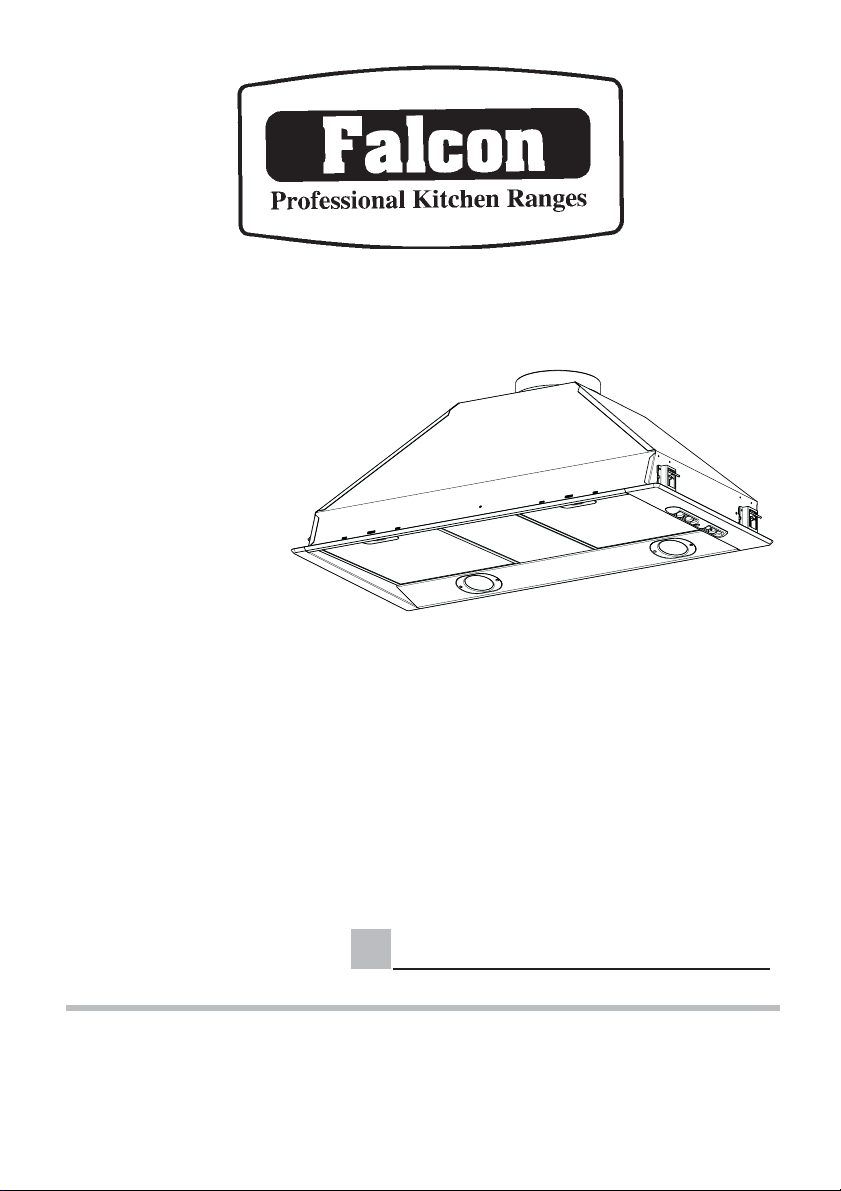
• Check that the mains voltage corresponds to that indicated
on the rating plate fi xed to the inside of the hood.
• For Class I appliances, check that the domestic power supply
guarantees adequate earthing.
Connect the extractor to the exhaust fl ue through a pipe of
minimum diameter 120 mm. The route of the fl ue must be as
short as possible.
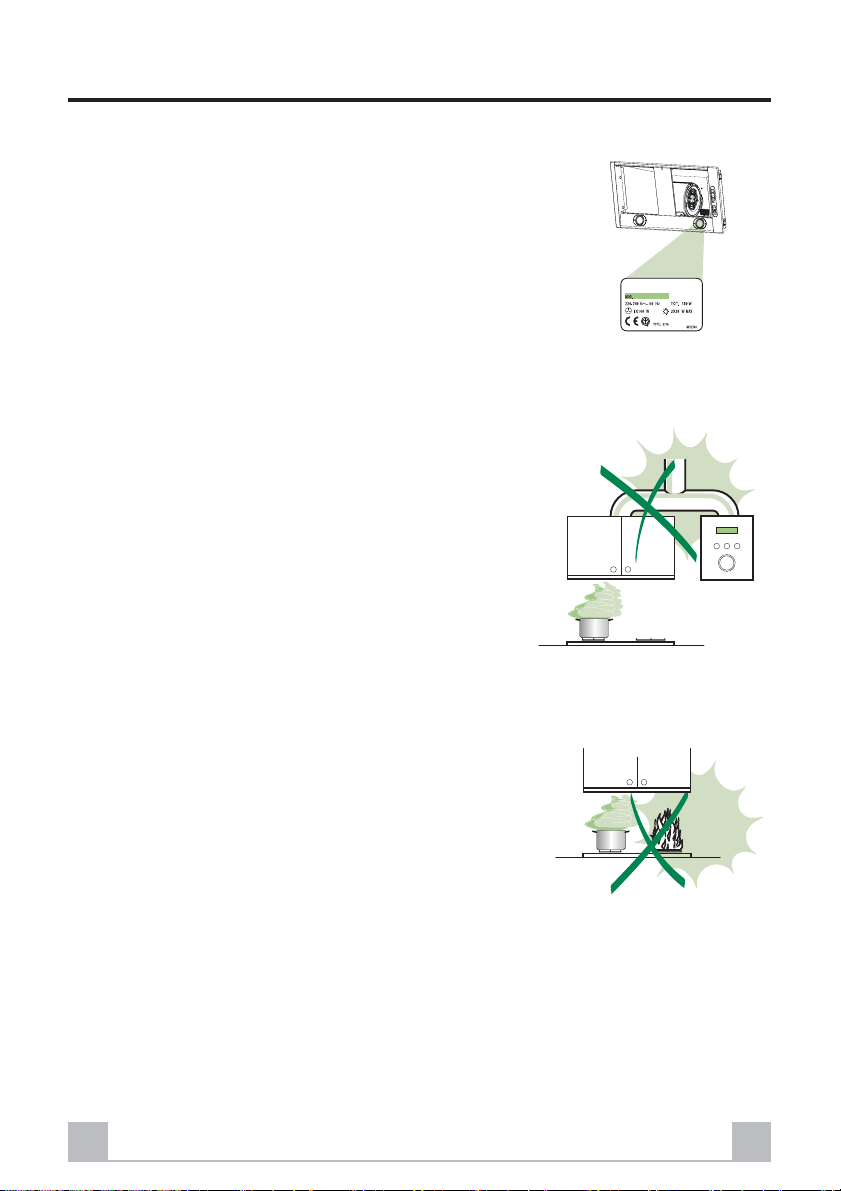
• Do not connect the extractor hood to exhaust ducts carrying
combustion fumes (boilers, fi replaces, etc.).
• If the extractor is used in conjunction with non-electrical
appliances (e.g. gas burning appliances), a suffi cient degree
of aeration must be guaranteed in the room in order to prevent the backfl ow of exhaust gas. The kitchen must have an
opening communicating directly with the open air in order
to guarantee the entry of clean air.
USE
• The extractor hood has been designed exclusively for domestic use to eliminate kitchen smells.
• Never use the hood for purposes other than for which it has
ben designed.
• Never leave high naked fl ames under the hood when it is in
operation.
• Adjust the fl ame intensity to direct it onto the bottom of the
pan only, making sure that it does not engulf the sides.
• Deep fat fryers must be continuously monitored during use:
overheated oil can burst into fl ames.
• The hood should not be used by children or persons not
instructed in its correct use.
MAINTENANCE
• Switch off or unplug the appliance from the mains supply
before carrying out any maintenance work.
• Clean and/or replace the Filters after the specifi ed time pe-
riod.
• Clean the hood using a damp cloth and a neutral liquid detergent.
GB
12
Page 4

CHARACTERISTICS
Dimensions
ø150
L1
Hood Type 54 72
L 540 720
L1 512 692
9
12c
240
L
Components
Ref. Q.ty Product Components
1 1 Hood Body, complete with: Controls, Light,
9 1 Reducer Flange ø 150-120 mm
Ref. Q.ty Installation Components
12c 2 Screws 2,9 x 6,5
Q.ty Documentation
1 Instruction Manual
1 Electric Diagram
Blower, Filters
370
240
175
400
GB
13
Page 5

INSTALLATION
Drilling the Support surface and Fitting the Hood
The Hood can be fi tted directly to the underside of the Wall units (min. 650 mm above the cooker
top) with snap-on side supports, which are set up for a support panel thickness of between 15 mm
and 30 mm.
• Cut a fi tted opening in the bottom surface of the
wall unit, as shown.
• Remove the metal grease fi lters (see par. on
Maintenance).
• Disconnect the fi lter support by turning the
internal handles provided.
• Insert the hood until the side supports snap into
place.
• Lock in position by tightening the screws Vf
from underneath the hood.
Hood Type 54 72
L2 515 695
GB
375
L2
Vf
14
Page 6

• Replace the fi lter support
• Screw the fi lter support using the 2 screws 12c (2,9 x 6 ,5) pro-
vided.
• Replace the grease fi lters make sure that the handle is visible on
the outside.
12c
Connections
DUCTED VERSION AIR EXHAUST SYSTEM
When installing the ducted version, connect the hood to the chimney using either a fl exible or rigid
pipe ø 150 or 120 mm, the choice of which is left to the installer.
• To install a ø 120 mm air exhaust connection,
insert the reducer fl ange 9 on the hood body
outlet.
• Fix the pipe in position using suffi cient pipe
clamps (not supplied).
• Remove any activated charcoal fi lters.
ø 150
ø 120
9
RECIRCULATION VERSION AIR OUTLET
• Drill a hole ø 120 or 150 mm in the shelf above the hood
and connect the hood canopy outlet to the top part of
the wall unit by means of a rigid or fl exible pipe of the
same diameter, the choice of which is at the discretion
of the installer.
• To install a ø 120 mm air exhaust connection, insert the
reducer fl ange 9 on the hood body outlet.
• Fix the pipe in position using suffi cient pipe clamps (not
supplied).
• Ensure that the activated charcoal fi lters have been
inserted.
9
ELECTRICAL CONNECTION
• Connect the hood to the mains through a two-pole switch having a contact gap of at least 3
mm.
GB
150
120
15
Page 7

USE
Control Panel
The hood can be switched on pushing directly onto the requested speed without fi rstly having to
select 0/1 button.
L
T1
T2
T3
T4
S1
KEY LED FUNCTIONS
L 0/1 Light Turns lighting on and off.
T1 0/1 Motor on First speed.
T2 Speed on Second speed.
T3 Speed on Third speed.
T4 Speed Fixed Max. speed
Flashing Intensive speed.
Suitable for the strongest cooking vapours and odours.
S1 Led Fixed Indicates that the Metal grease fi lters saturation alarm
Flashing indicates that the activated charcoal odour fi lter satu-
When pressed for about 2 seconds the motor is switched off.
The function becomes active when the button is pushed
for about 2 seconds. After 10 minutes of functioning it
turns off automatically. This function can be interrupted
by means of pressing any of the buttons.
has been triggered, and the fi lters need to be washed.
The alarm is triggered after 100 working hours. (Reset;
check the Maintenance-paragraph)
ration alarm has been triggered, and the fi lter has to be
replaced; the metal grease fi lters must also be washed.
The activated charcoal odour fi lter is triggered after
200 working hours. (Activation and Reset; check the
Maintenance-paragraph)
GB
16
Page 8

REMOTE CONTROL (OPTIONAL)
The appliance can be controlled using a remote
control powered by a 1.5 V carbon-zinc alkaline
batteries of the standard LR03-AAA type.
• Do not place the remote control near to heat
sources.
• Used batteries must be disposed of in the proper
manner.
MAINTENANCE
Grease fi lters
CLEANING METAL GREASE FILTERS
Alarm signal reset
• Switch of the lights and extractor motor.
• Press button T3 for at least 3 seconds, until the
leds start to fl ash.
Cleaning the fi lters
• The fi lters are washable and must be cleaned
when led S1 fl ashes or at least every 2 months
of operation, or more frequently for particularly
heavy usage.
• Remove the fi lters one at a time, supporting
them with one hand and turning the safety
knobs (pull and turn).
• Wash the fi lters, taking care not to bend them.
Allow them to dry before refi tting.
• Replace them and fi x them using the safety
knobs provided (pull and turn).
GB
17
Page 9

Activated charcoal fi lter (Recirculation version)
REPLACING THE ACTIVATED CHARCOAL FILTER
• The fi lter is not washable and cannot be regene-
rated. It must be replaced when led S1 fl ashes
or at least every 4 months. The alarm signal
will only light up when the extractor motor is
switched on.
Alarm signal reset
• Switch off the lights and extractor motor.
• Press button T3 for at least 3 seconds, until the
leds start to fl ash.
Replacing the Filter
• Remove the grease fi lters.
• Remove the saturated activated charcoal fi lters
as shown (A).
• Fit new fi lters (B).
• Replace the grease fi lters.
Alarm signal activation
• In Recirculation version Hoods, the Filter saturation alarm can be enabled on installation or at a
later date.
• Turn the Lights and the suction Motor off.
• Disconnect the Hood using the Main switch or the double-pole switch on the mains power supply.
• Restore the connection by pressing and holding T1.
• Release the button. All fi ve LEDs are turned on
• Within 3 seconds press T1 until LEDs T1 and T4 fl ash in confi rmation:
LED fl ashes twice - Activated charcoal fi lter saturation alarm ENABLED
LED fl ashes once - Activated charcoal fi lter saturation alarm DISABLED
B
A
Lighting
LIGHT REPLACEMENT
50 W halogen light.
• Remove the 2 screws fi xing the light cover.
• Remove the lamp by gripping the protruding
part and turning to the left.
• Replace with a new lamp with the same characteristics, making sure that you insert the two
pins properly into their housings.
• Replace the cover and fi x it in position using
the two screws removed as above
GB
18
 Loading...