

Rangemaster IGNEOUS Installation Instructions & Aftercare Information

Instructions for:
Andesite and Scoria sinks
IGNEOUS GRANITE SINKS
Installation Instructions
&
Aftercare Information
U110645-01
Due to our policy of continual improvement, we reserve the right to change specications without prior notice.
INSTALLATION
Installer
Please leave this leaet with the user, as it contains valuable
after care advice.
Tools Required
Ruler/Tape Measure Pencil
Masking Tape Safety Glasses
Kitchen Silicone Sealant Screwdriver
Hammer
35mm Hole Saw
(for cutting tap hole)
Drill
Jigsaw & Suitable Blade (if
work top cutout is required)
Notes
During installation, take care to protect the sink
from scus and scratches.
Do not stand on the sink.
During installation, do not stand the sink on its
edges or corners. This may cause damage.
Avoid straining and over tightening of all plumbing
xtures connected to the sink.
Carefully check that the moulding and edges of the
sink are dead level so that water will ow o the
drainer.
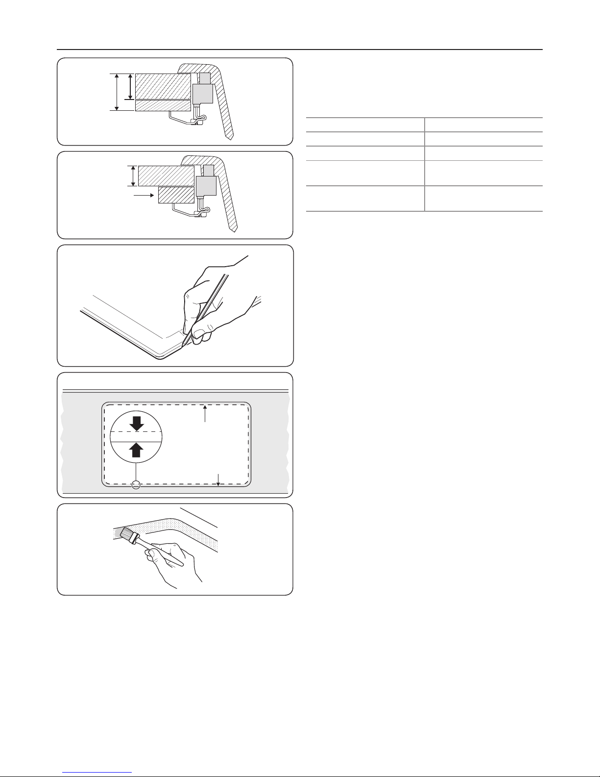
The clamping brackets are suitable for worktops
of between 30–40 mm thickness (Fig. 1.1). If your
worktop is a dierent size then it may require
packing under the clamps or rebating (Fig. 1.2).
Preparing the Worktop
Marking Out the Opening
We recommend that you t the sink to the worktop before
permanently xing the worktop to the cabinet.
1. Place the sink upside down on the worktop. Position
the sink on the worktop as required. Make sure the
cabinet framework will clear all parts of the sink. Using a
soft, sharp pencil draw around the sink as accurately as
possible (Fig. 1.3). Remove the sink.
2. Draw another line 10 mm inside the sink top outline –
this is the cutting line for the opening (Fig. 1.4).
3. Drill as large a hole as possible inside the cutting line.
Using a pad saw, jigsaw or similar, cut out the opening
up to the cutting line.
Sealing the Edges of the Opening.
We recommend that porous edges around the cut-out are
sealed using a waterproof sealant such as varnish, paint or
wood glue . This will prevent swelling of the worktop should
any small leaks occur (Fig. 1.5).
Worktop
Final position
of sink
Cutting line for opening
10 mm
30
mm
40
mm
+
x
Less than
30
mm
Fig. 1.1
Fig. 1.2
Fig. 1.3
Fig. 1.4
Fig. 1.5
 Loading...