

Page 1
RK12 Bathing Tub
Quick Reference Guide
NOTHING’S MORE REFRESHING THAN RANE
*Shown with optional equipment
Page 2

INSRUCTIONS PERTAINING TO A RISK OF FIRE,
ELECTRICAL SHOCK, OR INJURY TO PERSONS
READ AND FOLLOW ALL INSTRUCTIONS
WARNING - When using this unit, basic precautions should always be followed, including the
following:
READ AND FOLLOW ALL INSTRUCTIONS.
DANGER: To reduce the risk of injury, do not permit children to use this unit unless
they are closely supervised at all times
Use this unit only for its intended use as described in this manual. Do not use
attachments not recommended by the manufacturer.
Never drop or insert any object into any opening.
Do not operate this unit without the guard over the suction fitting.
The unit must be connected only to a supply circuit this is protected by a ground-fault
circuit-interrupter (GFCI). Such a GFCI should be provided by the installer and should
be tested on a routine basis. To test the GFCI, push the test button. The GFCI should
interrupt power. Push the reset button. Power should be restored. If the GFCI fails to
operate in this manner, the GFCI is defective. If the GFCI interrupts power without the
test button being pushed there is a ground current flowing, indicating the possibility of an
electric shock. Do not use this hydromassaged tub. Disconnect the hydromassaged
bathtub and have the problem corrected by a qualified service representative before
using.
(For permanently connected units) A green colored terminal (or a wire connector marked
“G”, “GR”, “Ground”, or “Grounding”) is provided within the terminal compartment. To
reduce the risk of electric shock, connect this terminal or connector to the grounding
terminal of your electric service or supply panel with a conductor equivalent in size to
the circuit conductors supplying this equipment.
DANGER: RISK OF ELECTRICAL SHOCK. Connect only to a circuit
protected by a ground-fault circuit-interrupter.
Grounding is required. The unit should be installed by a qualified
service representative and grounded.
(For built-in and custom units) Install to permit from servicing.
SAVE THESE INSTRUCTIONS
Page 3

Technical Specifications
STANDARD UNIT: MODEL # RK12
PERFORMANCE DATA: SERVICE CONNECTIONS:
MANUFACTURING AND TESTING: WARRANTY:
____________________________________________________________________________________________
RANE RK12 Page 1.1
Section
1
Tub Capacity: 58 Gallons
Occupied Tub Capacity (approx.): 48 Gallons
Thermostatic Mixing Valve: 20 gpm
Approximate Fill Time (48 gallons): 2.4 min
Drain Flow Rate: 1.5” Drain-1.92 minutes
Drain: 2” inlet with a 1 1/2” PVC outlet
Electrical for Air Blower Options:
115V AC, 60Hz, 15A service with a GFI Circuit
(not supplied by RANE)
This unit is manufactured in Sparta, Tennessee,
USA. Each unit passes a through quality control
review and is tested for proper operation prior to
shipping. This unit is manufactured to meet or
exceed the following: ASME/ANSI A112.19.1M
IAPMO/UPC, Canadian Standards Association
Please reference section 5 for complete warranty
details.
Description: Model RK12 is a freestanding, 58-gallon side access bathing tub.
Construction: The tub shell consists of a 3/16” thick fiberglass-reinforced polyester laminate. Critical areas are
reinforced with a 1/4” thick core of end-grain balsa and additional layers of fortifying laminate. The sanitary gelcoat is an
ISO/NPG type-finish. Tub Frame is welded aircraft grade aluminum box tube.
Side Access Door: The watertight right hinged door has a compression-type seal that is Teflon impregnated.
Equipment Access Panel: A removable panel provides access to all plumbing and valves.
Control Panel and Valves: The beautifully contoured integral control panel provides convenient control of the bathing
environment without the need for a wall mounted console. The thermostatic mixing valve utilizes a maximum
temperature setting feature to prevent accidental scalding. Water flow to the tub is controlled by a 3/4" valve. A 1/2"
valve controls water flow to the hand-held shower. A solar thermometer measures the temperature of the water after it
leaves the mixing valve and prior to discharging from the tub spout.
Disinfection System: The built-in disinfection system eliminates the need for specifications and installation of a wall
mounted system. A shelf for a gallon container of disinfectant chemical is provided under locked cabinet in the rear of
the tub. The flow rate can be adjusted by a DEMA valve. The wand and hose are conveniently located to remain out of
the way during bathing.
Hand-Held Shower: A chrome, hand-held shower with flexible hose that retracts out of site is mounted to the deck of
the tub.
Drain and Overflow Assembly: An ample 1.5" drain is installed with an overflow.
Grab Bars: One 7.5” grab bar is firmly mounted to the interior wall of the tub. A grab bar is also mounted on the inside
of the side access door.
Leveling Legs: The sturdy stainless steel leveling legs will adjust up to 2” per leg.
Air Spa Option: The air spa system features a control system that allows for increasing the air flow at a gradual speed at
the push of a button. A ceramic heating element provides warm air that helps maintains the water temperature and warms
the surface of the tub. Backflow prevention spring loaded jets eliminate the need for back flushing air lines, providing for
longer life than rubber flap style jets.
Page 4
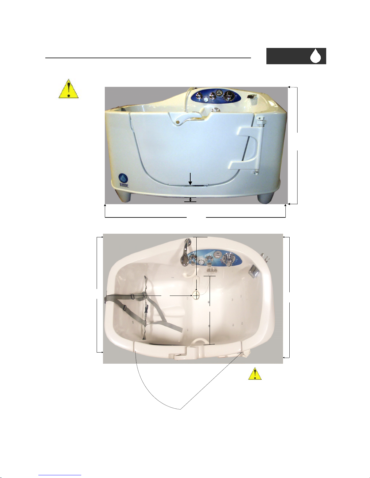
Pre-Installation Drawings and Dimensions
42.5"
61.5"
7.5"
Section
2
FRONT VIEW
TOP VIEW
Allow 41”
for door
swing
____________________________________________________________________________________________
RANE RK12 Page 2.1
Vertical dimensions
are with the tub in the
lowest position. The
seat height is 19” If
legs are extended and
tub is raised, adjust
the dimensions
accordingly
28"
11"
33.5"
30"
22.5"
Note: To
Outside
3.5"
Page 5
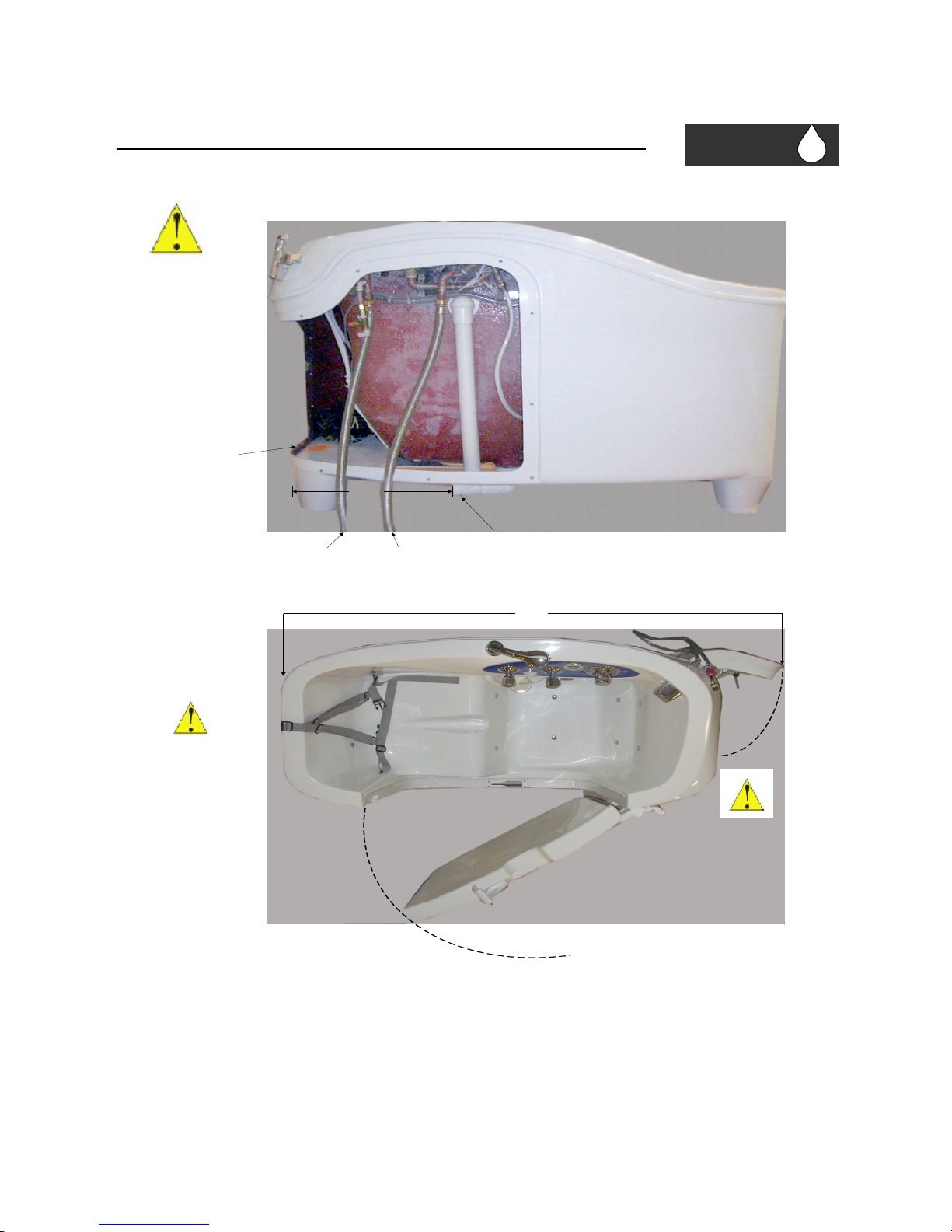
Pre-Installation Drawings and Dimensions
Seat End
Access Panel End
18.5"
1.5" Sanitary Tee
(8" From Floor)
5' Cold
Water Hose
5' Hot
Water Hose
Section
2
PLUMBING VIEW
____________________________________________________________________________________________
RANE RK12 Page 2.2
All connections made
through access
opening provided
under tub.
Door hinge on right
side of tub only.
Verify placement and
door swing before
final placement of
unit.
SPACE REQUIREMENT TOP VIEW
75"
8' Electrical cord with
standard NEMA 5-15 Plug
Allow for 13.5” for
Access panel swing
Allow for 40”
Door Swing
Page 6
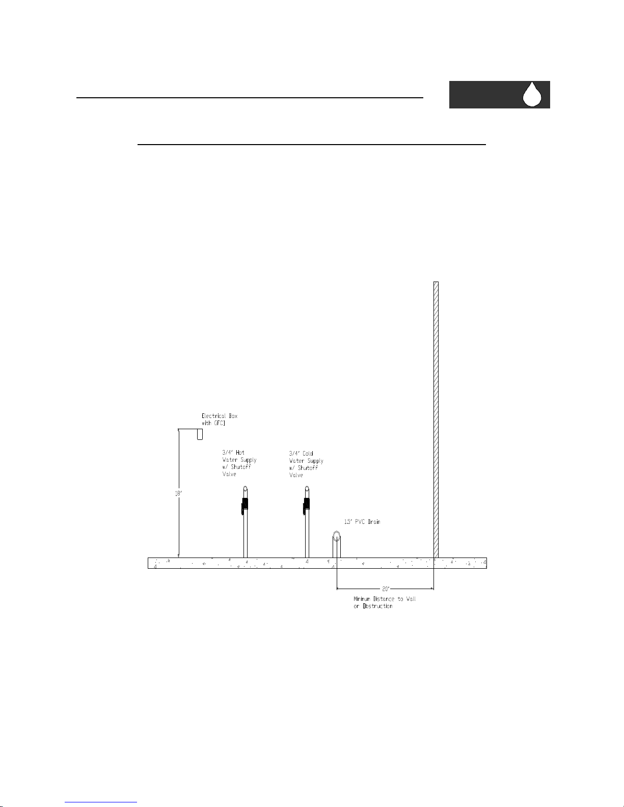
Pre-Installation Drawings and Dimensions
Suggested Plumbing and Electrical Layout
Section
2
____________________________________________________________________________________________
RANE RK12 Page 2.4
Page 7
Installing the Tub
The RK12 is designed to be installed as a freestanding unit, but can be built into an alcove. Several items
of precaution should be taken during installation:
USE THIS PRODUCT ONLY FOR ITS INTENDED USE AS DESCRIBED FURTHER IN
THESE INSTRUCTIONS.
DURING CONSTRUCTION, THE TUB’S SHELL IS VULNERABLE TO DAMAGE
CAUSED BY FALLING OBJECTS. DO NOT STAND IN THE TUB FOR INSTALLATION.
NEVER STORE OTHER CONSTRUCTION MATERIALS INSIDE THE TUB.
PRINTED DIMENSIONS ARE FOR REFERENCE ONLY. ACTUAL MEASUREMENTS
SHOULD BE TAKEN FROM THE TUB.
THE TUB MUST BE WATER TESTED FOR LEAKS BEFORE THE TUB IS
COMPLETELY ENCLOSED AND INSTALLED.
Step #1: Determine final location and review framework for the unit. Rough-in plumbing and electrical
hook-ups according to relevant building codes and regulations. This unit is a freestanding tub
designed for easy access to controls by attendant. Please review Section 2 for rough in dimensions
and allow for spacing as listed plus any requirements for lifting devices.
Check all applicable building codes. All electrical and plumbing work must be
performed by qualified personnel!
Step #2: Remove all packing material and cardboard from the unit. Set aside accessory box which was
shipped inside access compartment. Remove tub from pallet. Make sure the door is in the closed
position for installation. This will allow proper installation and help maintain the true shape of the tub
unit itself.
Step #3: Slide tub into place to verify there are no interference issues between connections and tub.
Level the tub in its final location. Then slide the tub back into the working area.
Section
3
____________________________________________________________________________________________
RANE RK12 Page 3.1
Page 8
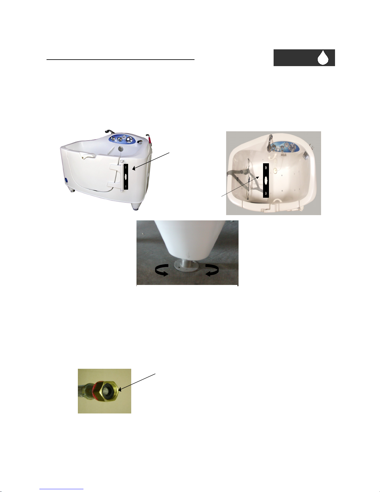
Level “Side to Side”
Installing the Tub (continued)
Step #4: Level the unit by turning the adjustable legs to raise or lower the unit. This should be done
before doing anything else. Check to see that the unit is level by using a 2’ level across the back and side
of the tub. Before fastening the unit, open the door and make sure it does not swing open or close by
itself.
Step #5: Clean water lines of debris prior to connection. Valves, shower heads, and accessories may
become clogged or damaged if the lines are not clear. Warranty does not cover damage caused by
debris in the water lines.
Step #6: Connect the hot and cold water inlet hoses to facility plumbing. Make sure that the hose
screens are present (see below) and the hoses are not bent or kinked. The threaded connections are NOT
“hose thread”, but rather “National Pipe Thread” (NPT).
Section
3
____________________________________________________________________________________________
RANE RK12 Page 3.2
Make sure hose screen is present and
inserted in hose end properly
Level “Front to Back”
To Lower Tub To Raise Tub
Page 9
Installing the Tub (continued)
Step #7: Set tub back into place, re-check level.
Make sure the unit is level prior to fastening to the floor.
Do not over tighten the floor connections. This could cause the unit to be un-level.
Step #8: Make drain connection from sanitary tee on tub to facility drain.
If mobile lifts are to be used for transferring patients, verify that the lift base
clears the drain connection. If possible damage might occur to drain area, you
must install blocking or a stop to prevent contact between lift base and plumbing.
Step #9: If tub has an air spa blower, plug the electrical cord into the GFI Outlet.
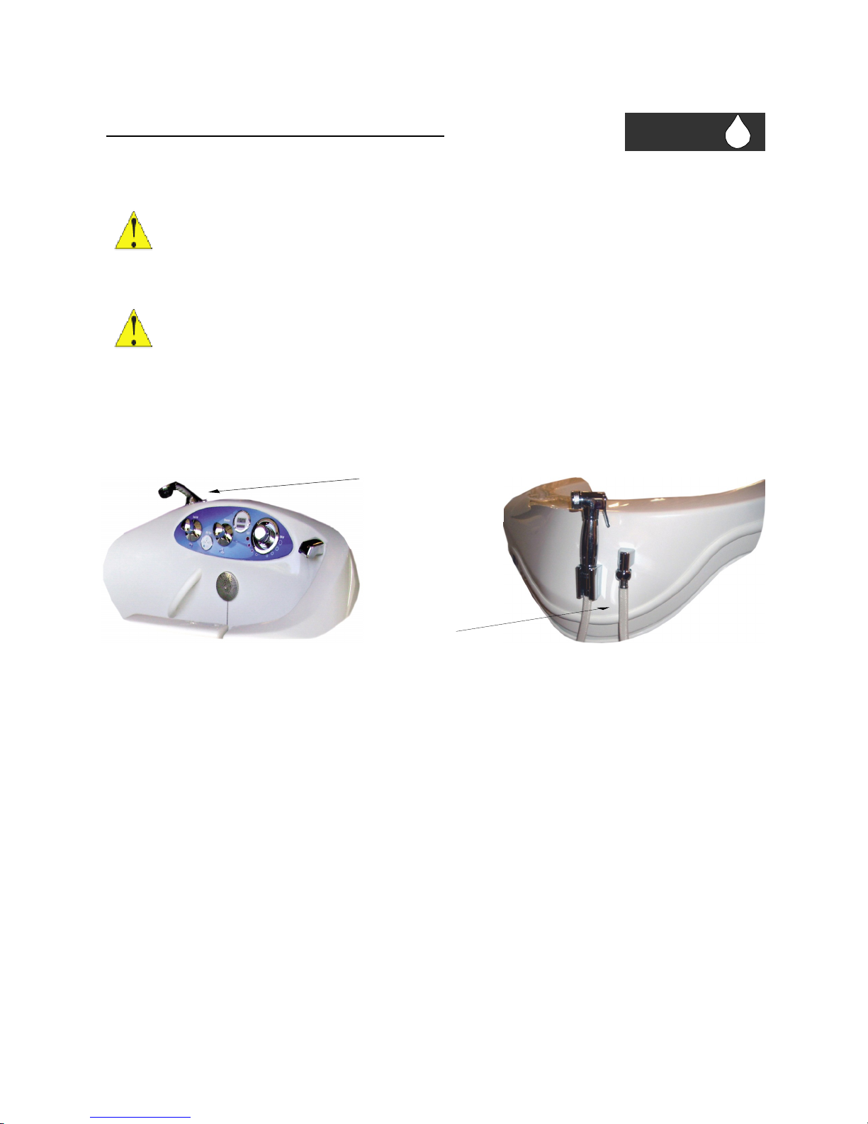
Step #10: Attach any accessories, including shower wand and disinfect hose assembly as shown below.
The shower hose is concealed inside tub, and can be pulled out.
Step #11: Test unit for proper operation. Be sure to clean inside of tub prior to filling unit. Excess debris
may damage the air blower. Check the unit for any leaks.
Step #12: Remove any installation labels and directions. Clean tub and prepare for daily use with warm
water and non-abrasive cleaner.
NOTE: The thorough inspection and startup of the tub is required before first use. It is the
installer’s responsibility to check for and tighten as necessary threaded connections on all parts of
tub as part of this start-up procedure.
____________________________________________________________________________________________
RANE RK12 Page 3.3
Section
3
Attach Shower
Wand Here
Attach Disinfect Hose
Assembly Here
 Loading...