

Page 1

NBKING100
Nuno Bettencourt
Signature Series
Page 2
QUICK START GUIDE
START UP
After you have plugged in and connected the AC power cord securely from the
wall to the amplier, connect only a high quality speaker cable from the Speaker
output jack to the input jack of your extension cabinet. Make sure that you plug
into the correct Speaker output jack which matches the impedence of your cabinet.
For example: If you have a 16 ohm cabinet then make sure you are plugged into
the jack labeled 16 ohms. Now that the amplier has been hooked up
correctly, simply plug your guitar into the front panel Input jack using a high
quality instrument cable and ip the Power switch to ON.
Once the amplier is powered up it will default to the the Clean channel. Set all
the Drive, Level & EQ controls to straight up except for the large Master
control which should be set all the way down. Turn the amp from Standby to On
then bring up the Master control slowing until you reach the desired volume level.
This
channel is perfect for all clean tones, but really shines for Funk style as well as
vintage blues tones.
Page 3
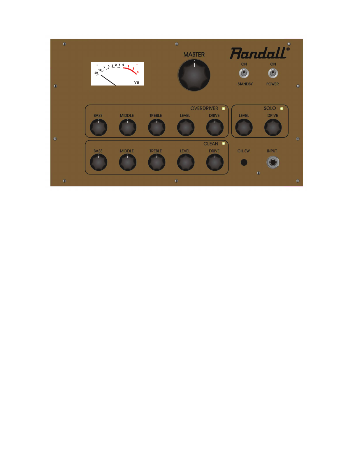
FRONT PANEL FEATURES
INPUT
Designed to accept a standard 1/4” mono phone plug. For best results use a
high quality shielded cable to connect your guitar to the amplier.
.
CHANNEL SELECT SWITCH
This momentary push button switch is used to scroll thru and select between the
3 channels on the amplier. Simply push and release to change channelsand select
the desired channel. This switch is also the store function for the included MIDI
footswitch or any MIDI compatible footcontroller. To store a channel to a particular
button on the footswitch, simply press the desired footswitch button then using the
front panel Channel select button scroll thru to the desired channel. Press, hold
& release the Channel Select button for 3 seconds to store the preset. See the
MIDI implemention guide later in this manual.
CLEAN
This channel was designed for a wide-range of dynamic clean tones, but really
shines for all funk to vintage style blues tones.
BASS - This passive tone control adjusts the amount of low frequencies in the
Clean channel. Set the knob straight up then adjust for more or less bass as
needed.
MIDDLE - This passive tone control adjusts a wide-range of the mid-range
frequencies in the Clean channel. When adjusting the MIDDLE control keep
in mind that you will also be cutting and boosting upper bass frequencies and
lower Treble frequencies. Set the knob straight up then adjust as needed.
TREBLE - Another passive tone control that adjusts all upper mid-range and high
frequencies. Set the knob straight up to start then adjust in more or less highs
as needed.
LEVEL - Controls the volume level of only the Clean channel. Set this knob to
achieve the desired output level of the clean channel.
Page 4

FRONT PANEL FEATURES-cont
SOLO
Voiced like the Overdrive mode, the Solo mode provides an addition option
for more or less Drive & Level in the Overdrive channel. Most players will
use the Solo mode for a lead or volume boost to the normal Overdrive channel.
LEVEL - Controls the output level of the Solo Overdrive channel. Use this knob to
achieve addti desired volume level for the Overdrive channel.
DRIVE - Controls the distortion level in the Overdrive channel. This amp was designed
to achieve a wide-range of gain levels, so set the control lower for more mid-gain classic
rock and funk tones or turned it up for full on modern rock and metal distortion.
VU METER
The VU meter measures the overall output of the amp. You will notice the VU Meter
.
is slighter higher when using the Clean channel, because the signal level is much cleaner
and stronger in this channel. Don’t be concerned if the VU meter hits the red area
occasionally, this just means you’re
Page 5

FRONT PANEL FEATURES-cont
SOLO
Voiced like the Overdrive mode, the Solo mode provides an addition option for more
or less Drive & Level in the Overdrive channel. Most players will use the Solo mode for
a lead or volume boost to the normal Overdrive channel
LEVEL - Controls the output level of the Solo Overdrive channel. Use this knob to
achieve addti desired volume level for the Overdrive channel.
.
DRIVE - Controls the distortion level in the Overdrive channel. This amp was designed
to achieve a wide-range of gain levels, so set the control lower for more mid-gain classic
rock and funk tones or turned it up for full on modern rock and metal distortion.
POWER
The main power switch to the amplier. Once the amplier is plugged in ip the Power
switch to the ON position. The VU Meter and Clean channel will light up indicating the
amplier is powered up and ready for action. IMPORTANT: Always make sure the Standby
.
is set to the Standby or OFF position anytime you turn ON or turn OFF the amplier.
STANDBY
Once the amplier has been powered up for a minimum of 30 seconds, you can ip
the Standby to ON and start playing. When turning the amplier OFF, turn
the Standby to the OFF position rst and let the power tubes cool down for a minimum
30 seconds before turning Power switch OFF.
VU METER
The VU meter measures the overall output of the amp. You will notice the VU Meter
is slighter higher when using the Clean channel, because the signal level is much cleaner
and stronger in this channel. Don’t be concerned if the VU meter occasionally hits the
red area.
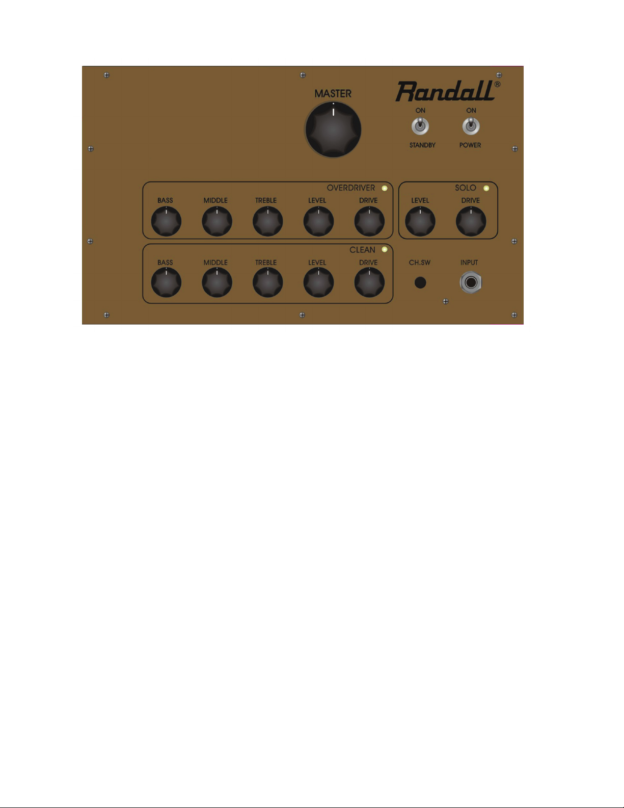
MASTER
This large knob controls the overall volume level of the amplier. Set the level control
on each channel rst then bring up the Master volume to the desired level. This knob
increases the volume gradually, so don’t be shy about turning the Master knob up as
high as you like. The amplier will continue to get louder without distorting to quickly.
Page 6

REAR PANEL FEATURES
.
MIDI CHANNEL SELECTION:
The MIDI Channel (1 - 16) is selected via an internal four position DIP switch (S1). The
MIDI Channel must be selected with the power o.
CHAN.
S1-4
S1-3
S1-2
S1-1
1
on
on
on
on
2
on
on
on
o
3
on
on
o
on
4
on
on
o
o
5
on
o
on
on
6
on
o
on
o
7
on
o
o
on
8
on
o
o
o
9
o
on
on
on
10
o
on
on
o
11
o
on
o
on
12
o
on
o
o
13
o
o
on
on
14
o
o
on
o
15
o
o
o
on
16 o
o o
o
FOOTSWITCH
The amplier includes a 3-button MIDI footswitch for switching between the 3 channels.
The amplier was designed with MIDI channel switching circuit that is compatible
with other MIDI compatible units like rackmount Eects processor. With the
amplier OFF, simply connect th 7-pin cable to MIDI IN jack on the rear panel of
the amplier. Use the MIDI THRU to connect to other MIDI compatible devices.
MIDI CHANNEL SWITCHING/STORING
Pressing and holding the channel select button for 2 seconds on the front panel
will store settings. To Store a preset or reprogram the footswitch simply press button 1
on the foot switch then if needed select the Clean (Ch 1) using the Channel select button.
Press and hold the channel select button for 2 seconds and button 1 on the footswitch is
now programmed to select the Clean (Ch 1) on the amplier. Repeat the same process
above to program button 2 on the footswitch to the Overdrive (Ch 2) and button 3 on the
footswitch to Solo (Ch 3)
.
MIDI IMPLEMENTATION
The EMB board recognizes Program Changes or Control Changes (Not Both) on a preselected MIDI channel. See the above for MIDI Channel Selection. Program changes 1
to 128 select EMB presets 1 to 128 which are saved in EEPROM memory.
Page 7

REAR PANEL FEATURES
MIDI IMPLEMENTATION - cont
Control Change #56 (w/control Value 127) allows for Instant Access selection of Channel 1.
Control Change #57 (w/control Value 127) allows for Instant Access selection of Channel 2.
Control Change #58 (w/control Value 127) allows for Instant Access selection of Channel 3.
The rst valid MIDI message (Program Change or Control Change) that the EMB board
receives will determine how it repsonds to subsequent MIDI messages. For example;
(A) if the rst MIDI message the EMB board receives is the Program Change, then it will
ONLY respond to Program Changes and all Control Change messages will be ignored.
(B) if the rst MIDI message the EMB board receives is a Control Change, then it will ONLY
respond to Control Changes and all Program Change messages will be ignored.
POWER TUBE BIAS SECTION
You will need a decent quality digital voltmeter capable of measuring in the 100mVDC
range. This is a basic type of meter available at any electronic supply company or Radio
Shack. Typical cost will be $15-$30 or about the cost of one bias adjustment from your
local amp technician. You will also need a small at blade screwdriver to turn the
adjustment control.
To check and/or adjust the bias, turn both the Power and Standby to the ON position and
all knobs all the way down. Turn the meter on and set for reading DC millivolts. Insert
the Black (Negative) meter lead into the panel hole label “COM” or Common. Insert the
Red (Positive) meter lead into either panel hole marked TEST POINT. With your screwdriver
turn the BIAS ADJUST control to obtain a recommended reading of 80mVDC. Now place the
red meter lead into the other BIAS ADJUST and also set to 80mVDC. On this amplier you
are adjusting a pair of tubes at one time, so 80 millivolts DC is the standard factory setting
for each pair, but adjust the bias range from 70 - 90mVDC if desired for a certain sound.
A lower bias setting will increase the life of your tubes, but produce a softer more bottom
heavy feel. A higher bias setting will decrease the life of your tubes, but produce a more
compressed harder tone and feel. If replacement tubes are needed you will need to
purchase the tubes in matched pairs. This amplier will accept any EL34 or 6L6 type of
power tube and the bias setting for either type will be the same.
EFFECTS LOOP
 Loading...