

Page 1
LF
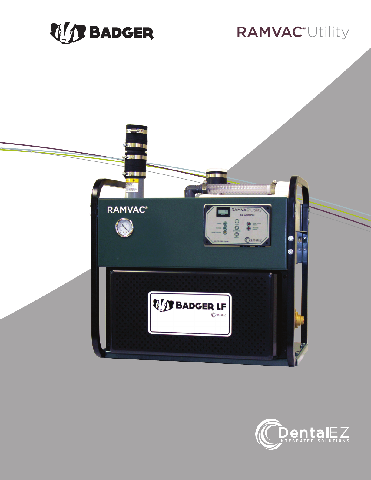
Badger LF
User Manual
Page 2

Table of Contents
Section I Introduction
Classications .............................................................................................................. 2
Safety Information........................................................................................................ 2
Explanation of Signs and Symbols.......................................................................... ... 3
Specications ............................................................................................................... 3
Packaging............................................................................................................. ........4
Section II Installation
Product Features..................................................................................................... .....5
Vacuum and Drain Plumbing ....................................................................................... 6
Drain Valve Plumbing Options.................................................................................. 7-9
Electrical ......................................................................................................................10
Muler Installation.................................................................................................. .....11
Exhaust Plumbing .......................................................................................................12
Section III Operation
E2 Control Features ....................................................................................................13
E2 Faults ......................................................................................................................13
Turning the System On/O .........................................................................................14
Shutdown Cycle...........................................................................................................14
Vacuum Level ..............................................................................................................14
Separation Tank ..........................................................................................................14
Section IV Care
Maintenance Overview .............................................................................................. .15
Preventative Maintenance Schedule .........................................................................15
Cleaning the Vacuum System ....................................................................................15
Cleaning the Vacuum Unit.................................................................................... ......16
Changing the Air Filter ................................................................................................16
Pump Head Exchange ................................................................................................16
Check Poly V-Belt ........................................................................................................ 16
Section V User Service Information
Troubleshooting .......................................................................................................... 17
Section VI Electrical Connections.......................................................................18
Section VII System Schematics ...........................................................................19
Section VIII Parts List/Diagrams
Regular Maintenance Kit ...........................................................................................20
Mechanical Replacement Parts Kits ..........................................................................21
Electrical Replacement Parts Kits ............................................................................ 22
Limited Warranty ........................................................................................................ 23
EMC Information................................................................................................... .24-25
www.DentalEZ.com 866-DTE-INFO (opt 4)
www.DentalEZ.com
1
1
Page 3

Section I Introduction
This manual contains installation, operation,
care, and repair instructions and user service
information for the RAMVAC® Utility Badger LF
dental vacuum system.
The main purpose of the Badger LF is to provide
a positive displacement, oil-less dry vacuum
system intended for use in a dental facility and
to be used by trained professional dental care
personnel only.
Badger LF is designed to provide trouble-free service
when installed, operated and cared for according to
the procedures set forth in this User Manual.
Badger LF User Manual
Safety Information
Here’s what you need to do to insure the safety
potential of this equipment is achieved:
• Make sure your equipment is installed ac-
cording to our written instructions and the
Installation Checklist is completed. If you have
purchased your RAMVAC from an authorized
dealer, the dealer is responsible for presenting
you with the completed checklist.
Vacuum is supplied to the system by a durable oilless rotary vane pump. A space-saving integrated
separation tank keeps liquid and foam out of the
pump. The E2 control provides precise electrical
control over run-time and shutdown operations
while vacuum is maintained at a uniform level by
the RAMVAC vacuum level control valve.
To ensure proper installation of the Badger
LF, carefully read all instructions contained
in this manual prior to installing, operating,
and servicing. For safety, pay close attention
to all notices, warnings, cautions and notes.
Classications
After the Badger LF is installed, please review the
features, operation procedures and care guidelines with the doctor's sta. Leave this manual in
the doctor's oice for future reference.
RAMVAC vacuum units are certied to ANSI/AAMI,
EX606-0-1:2005(R2012) and certied to CAN/CSA
Standard C22.2 No. 60601-11:08, and comply with
NFPA 99c Level 3 vacuum requirements, and are
manufactured in a FDA Registered ISO 13485:2003
certied facility.
– Type of protection against electric shock:
Class 1 Equipment
– Degree of protection against the ingress of
water: Ordinary
• Exhaust from dental vacuum systems can be
hazardous. Make sure the exhaust pipe is terminated outside your building according to our
written instructions.
• Nitrous oxide and oxygen can be safely scav-
enged in the small concentrations typically
encountered in dental analgesia. The additional
air drawn into a properly installed and operated
Vacuum Unit will dilute these agents.
• Never use your RAMVAC to remove pure nitrous
oxide, oxygen or other oxidizing agents directly
from storage vessels or supply hoses. Large
concentrations may cause a re in the Vacuum
Unit and may cause an exhaust hazard.
• Never use this equipment in an OXYGEN RICH
ENVIRONMENT. Large concentrations may
cause a re in the Vacuum Unit and may cause
an exhaust hazard.
• Never use your RAMVAC for housekeeping
functions.
• Never use your RAMVAC to collect lab dust.
www.DentalEZ.com
www.DentalEZ.com
866-DTE-INFO (opt 4)
2
2
Page 4
Section I Introduction
-29ºC
(-20ºF)
74ºC
(165ºF)
0%
95%
-29ºC
(-20ºF)
74ºC
(165ºF)
0%
95%
-29ºC
(-20ºF)
74ºC
(165ºF)
0%
95%
-29ºC
(-20ºF)
74ºC
(165ºF)
0%
95%
0%
95%
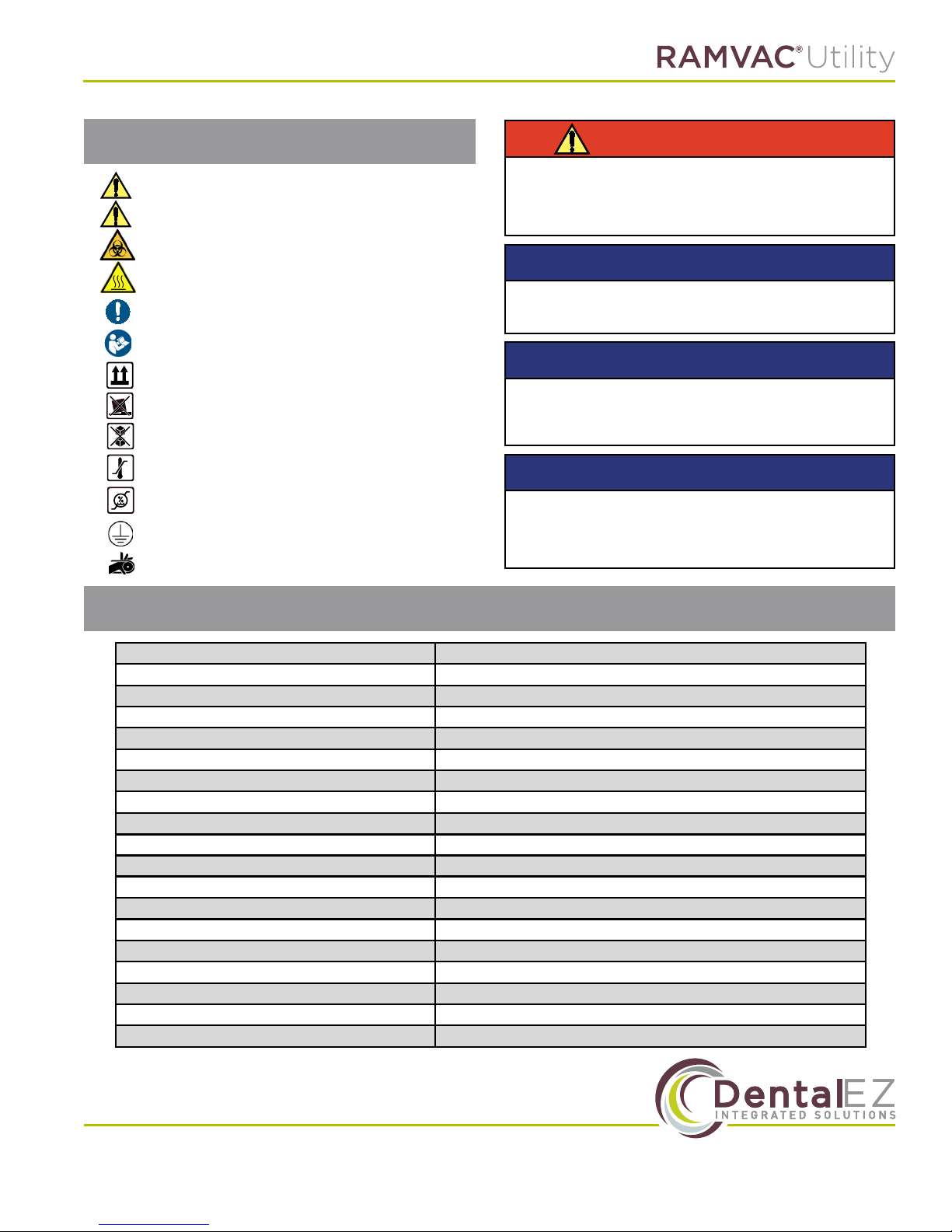
Explanation of Signs & Symbols
= Caution
= Warning
= Biohazard
= Hot Surfaces
= General Mandatory Action
= Refer to Manual (follow instructions)
= Box Must Remain Upright
=
= Do Not Stack Box
=
= Box Contents Safe Humidity Range
= Protective Earth
= Hazardous Moving Parts
Do Not Place Box On Unlevel Surface
Box Contents Safe Temperature Range
WARNING
Do not modify the Badger LF without
permission from RAMVAC. Modication will void
the warranty and could result in serious injury.
NOTICE
Installation by an authorized RAMVAC dealer
service technician is recommended.
NOTICE
For any questions about an order, please
contact a RAMVAC customer service
representative at 866-DTE-INFO.
NOTICE
The Badger LF Vacuum System must be
switched by a low voltage switch. It cannot be
switched with High Voltage.
Specications
Voltage 208-230 VAC, Single Phase
Frequency 60Hz only
Horsepower 1.5 HP
Full Load Amperes 6.2 Amps (Hi EFF motor)
Switching (low voltage) 24 VDC
Preset Vacuum Level 23.7 kPa (7" Hg)
Maximum Vacuum Level 50.8 kPa
Gauge Accuracy ASME/ANSI B40.1 Grade B (+/-3/2/3%)
Dimensions (WxDxH) 62.74 cm x 45.72 cm x 59.06 cm (24.7" x 18" x 23.25")
Floor to Drain Center Line 19.7 cm (7.75")
Weight 79.4 kg (175 lbs)
Tank Capacity 18.9 Liters (5 gallons)
Operating Temperature 4.4°C to 40°C (40°F to 104°F)
Storage Temperature -17.8°C to 65.6°C (0°F to 150°F)
Db Level 72db LF1 / 74db LF2
BTU Rating 900 btu/hr
Humidity in Transport/Storage/Operation 0% to 95% RH, no condensing moisture
Altitude in Operation 70-105 kPa (Sea level to 2,743m(9,000ft))
Altitude in Transport/Storage 50-105 kPa (Equates to 18,000 to - 1,000ft. elevation range
www.DentalEZ.com 866-DTE-INFO (opt 4)
www.DentalEZ.com
3
3
Page 5
Section I Introduction
Badger LF User Manual
Packaging
NOTICE
It is recommended to leave the unit attached
to the shipping pallet during transport until
nal destination.
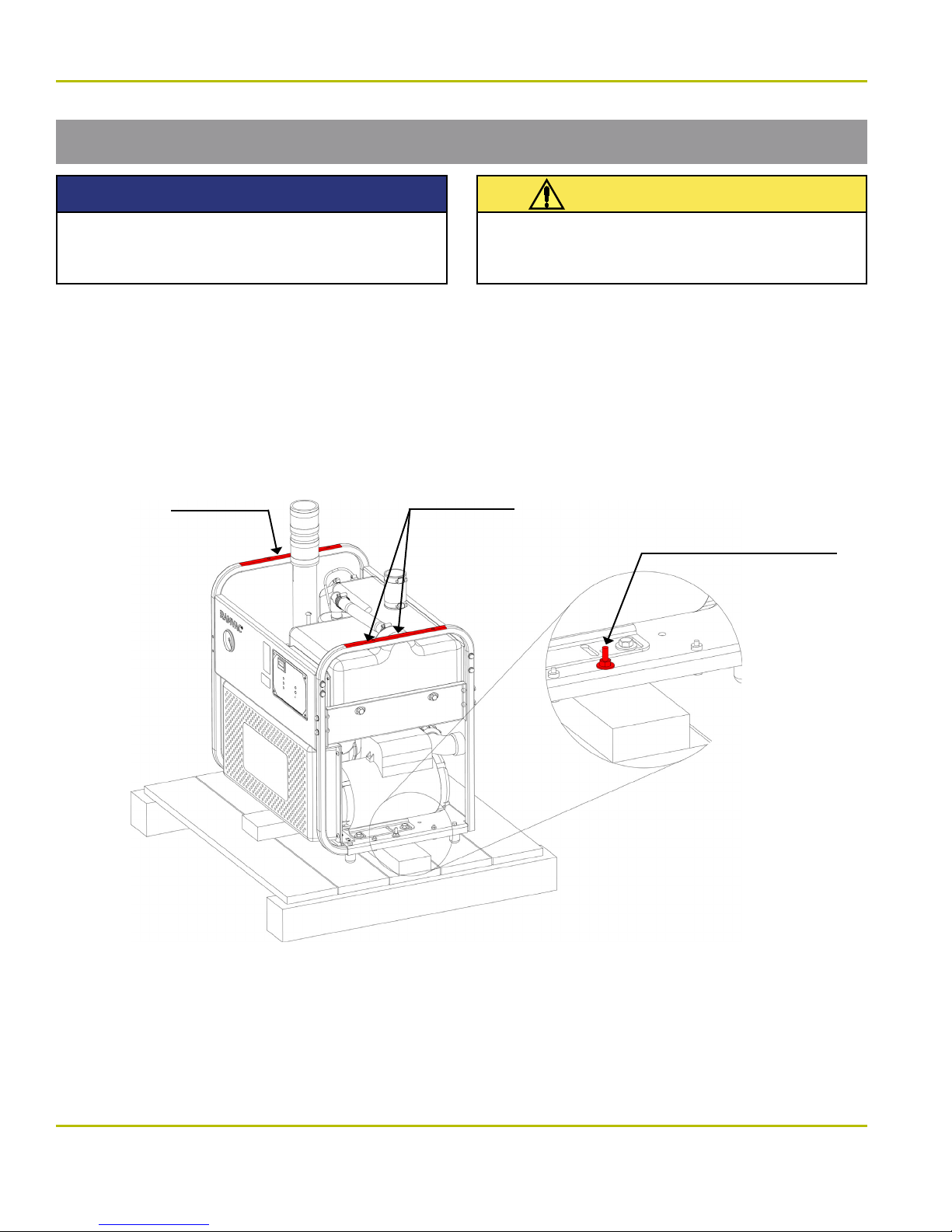
1. Carefully remove the shipping carton from the pallet containing the Badger LF.
2. Visually inspect the entire unit for damage. If shipping damage is found, immediately contact the
freight carrier and supplier.
3. Using a 7/16" wrench, unbolt both sides of Badger LF from the pallet.
4. To lift and handle the unit, grasp the frame rails shown in the gure below.
Lifting point
Lifting points
This unit is heavy. Never attempt to lift or
handle without assistance.
CAUTION
Use 7/16" wrench to
remove nut and washer
from both sides of pallet
5. Verify additional parts shipped with the Badger LF Vacuum Unit for use at installation:
• Installation Kit
• Facility Plumbing Adapter Kit
• Drain Plumbing Adapter Kit
• Badger LF Installation Packet
• Badger LF Doctor's Packet
www.DentalEZ.com
www.DentalEZ.com
• SlugBuster Starter Pack
• 2 cans SlugBuster Powder
• 2 Gallon SlugBuster Mixing Jug
• Badger LF Muler Kit
4
4
866-DTE-INFO (opt 4)
Page 6
Section II Installation
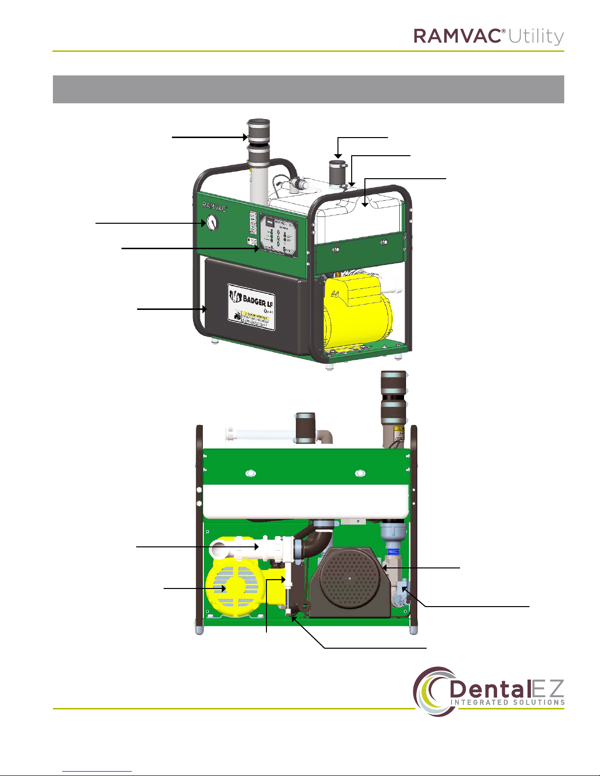
Product Features
Vacuum Gauge
E2 Control
Belt Guard
Exhaust
Tank Inlet
Tank Outlet
Separation Tank
Drain Check
Valve
Motor
www.DentalEZ.com 866-DTE-INFO (opt 4)
www.DentalEZ.com
Drain
Slide Valve
Power Conduit Whip
5
5
Pump
Exhaust
Drain Solenoid Valve
Page 7
Section II Installation
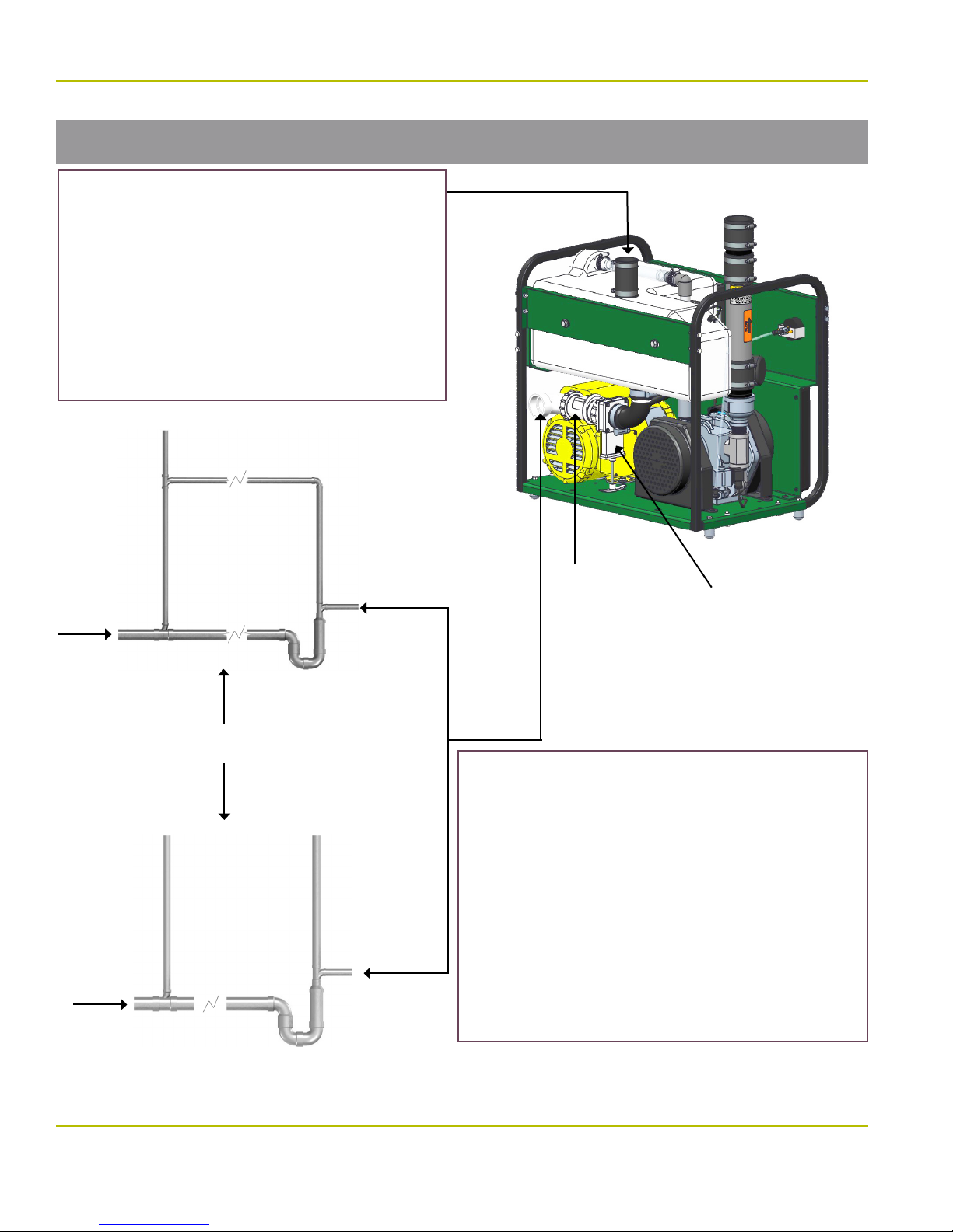
Vacuum and Drain Plumbing
Facility Vacuum Lines
• Build Like a Drain Line:
- Use DWV Fittings
- Minimum slope ¼” per 10 ft (2 mm per 1m)
• Can be adapted to t facility plumbing from 3/4” to 2”
• If an in-line low spot is unavoidable, place it in a
known location and incorporate a clean-out.
• For overhead piping, contact RAMVAC.
• For nitrous oxide scavenging, contact RAMVAC.
• Follow NFPA 99c Edition, RAMVAC Instructions, an
local codes.
Badger LF User Manual
To
Sewer
To
Sewer
Vent
Drain Line Options
NFPA 99c Edition
Vent
Drain Branch
Drain Branch
Trap
Trap Vent
Trap Vent
Drain
Check
Valve
Waste Pipe
Slide Valve
(must be open)
Tank Drain Line
• Waste Pipe, Slide Valve, and Drain Check Valve
- 1-1/2” PVC Schedule 40 with DWV ttings.
- Min. slope ¼” per 10 ft (2 mm per 1m).
- Use only RAMVAC supplied 1 -1/2” drain check valve.
• Trap and Drain Branch
-Trap and drain branch line 2 sizes larger than waste pipe.
-Trap seal minimum 4” deep.
• Vents
-Trap vent size no less than half the trap and drain branch size.
-Vents no smaller than drain check valve.
-Vents must extend minimum of 6” above tank top before
turning horizontal.
• Follow NFPA 99c Edition, RAMVAC Instructions,
and local codes.
Trap
www.DentalEZ.com
www.DentalEZ.com
866-DTE-INFO (opt 4)
6
6
Page 8
Section II Installation
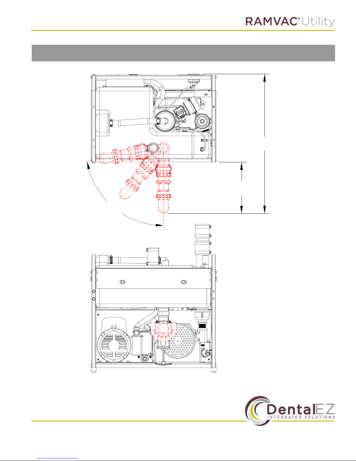
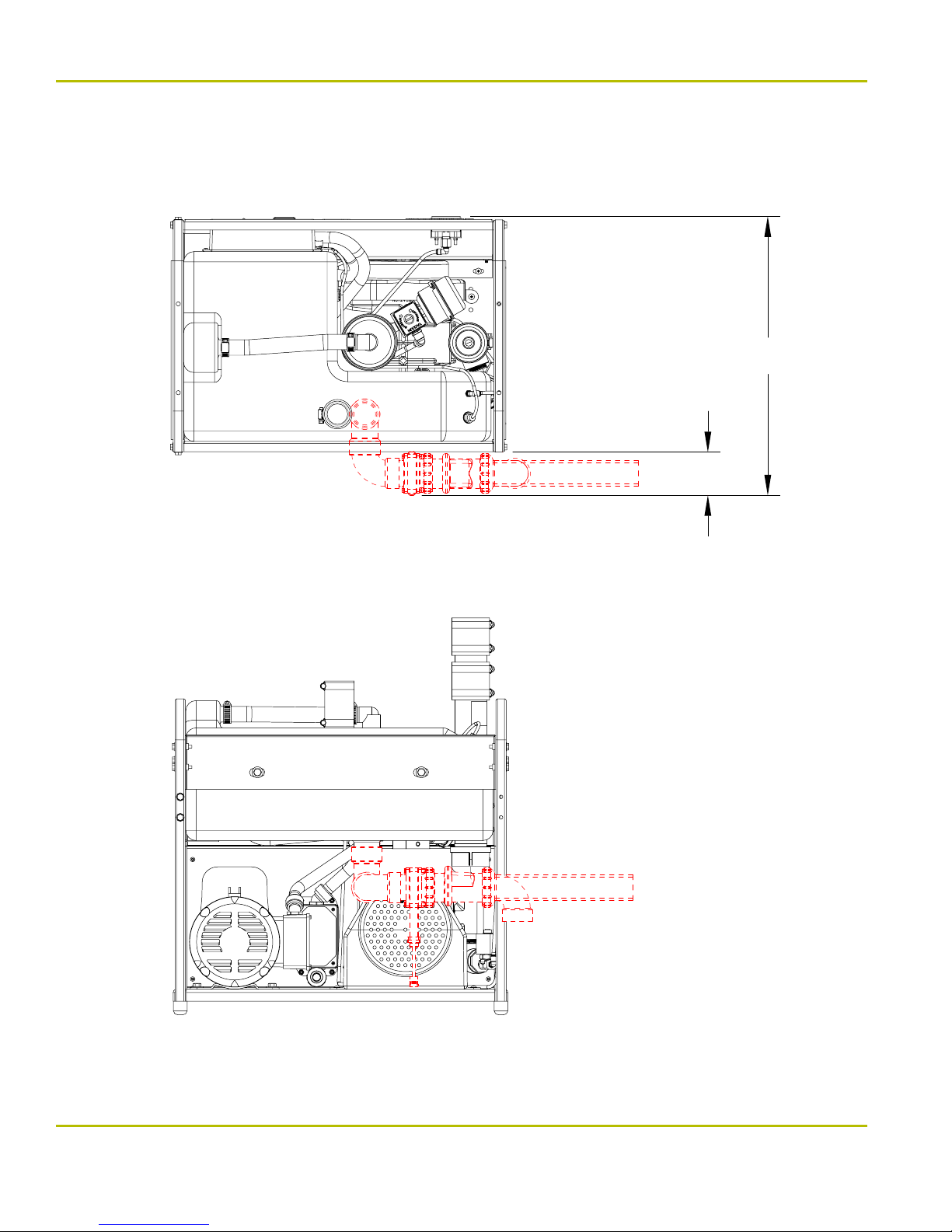
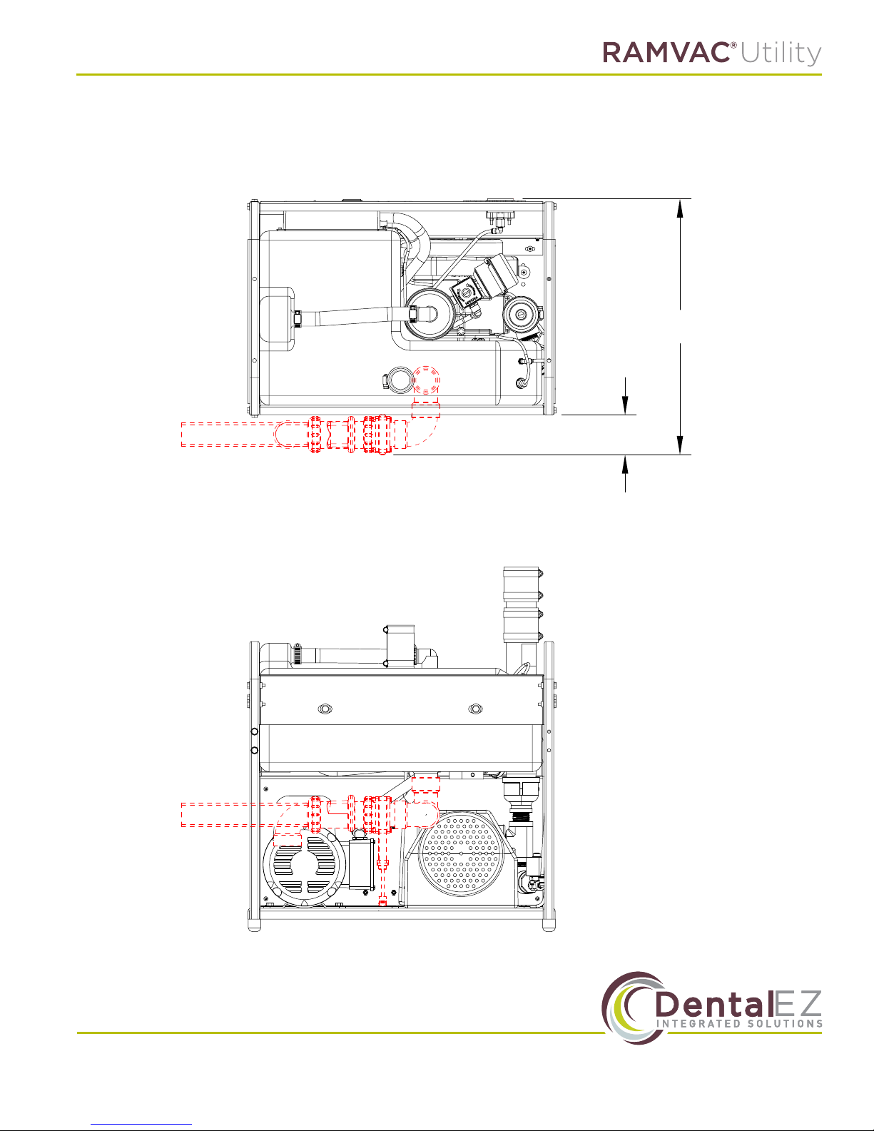
Drain Valve Plumbing Options
27.25"
10"
80˚
www.DentalEZ.com 866-DTE-INFO (opt 4)
www.DentalEZ.com
7
7
Page 9
Section II Installation
Badger LF User Manual
20.5"
3.25"
www.DentalEZ.com
www.DentalEZ.com
866-DTE-INFO (opt 4)
8
8
Page 10
Section II Installation
20.5"
3.25"
www.DentalEZ.com 866-DTE-INFO (opt 4)
www.DentalEZ.com
9
9
Page 11
Section II Installation
Badger LF User Manual
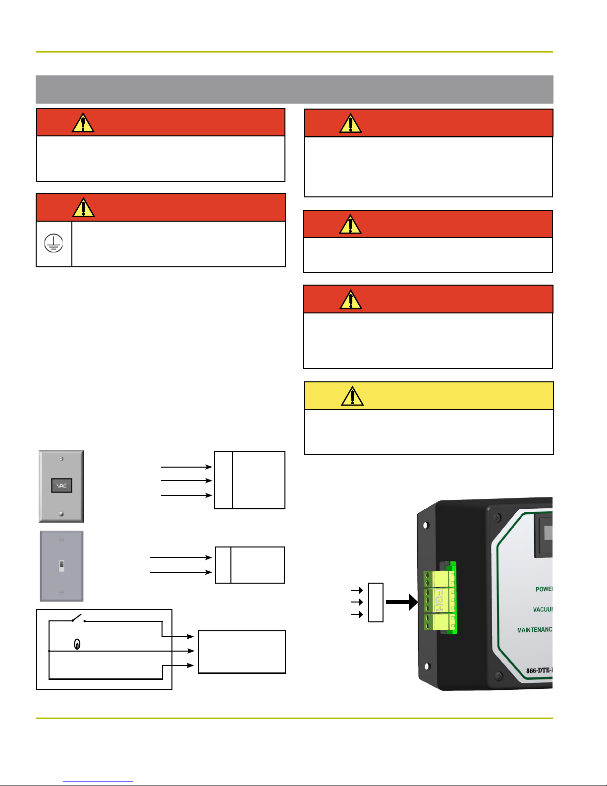
Electrical
WARNING
This device should only be installed by licensed
electrical and plumbing contractors to all applicable federal, state or local building codes.
WARNING
To avoid the risk of electrical shock, this
equipment must only be connected to a
supply mains with protective earth.
• Follow NEC, NFPA 99C, and all local codes.
• Vacuum pump is shipped with the appropriate
6' electrical power conduit whip.
• Qualied personnel must install a dedicated
electrical circuit.
• See “Specications” for more electrical
information.
RAMVAC
Remote Control
Panel or
equivalent with
illuminated
24v Switch
1.
2.
3.
F
G
H
E2 Control
Terminals
WARNING
Electrical shock could occur as a result of
improper grounding. This product must be
grounded according to NEC regulations and
local codes.
WARNING
Always turn o Vacuum pump and remove
power when servicing.
WARNING
Electrician must provide a means to isolate the
circuit electrically from the supply mains on
all poles simultaneously. It shall be capable of
being locked in the OFF position.
CAUTION
Use of an extension cord is not advisable. An
undersized extension cord will cause a drop in line
voltage and loss of power. Overheating will result.
Toggle Switch
or other
non-illuminated
switch
(option)
Vac Switch
Vac Light
Common
Illuminated Remote Switch
www.DentalEZ.com
www.DentalEZ.com
F
E2 Control
Terminals
H
F - +24v DC
G - +24v DC
H - 24v DC Control
E2 Control
Electrols
Terminals
10
10
Switch
Light
Common
F. G. H.
F. G. H.
866-DTE-INFO (opt 4)
Page 12
Section II Installation
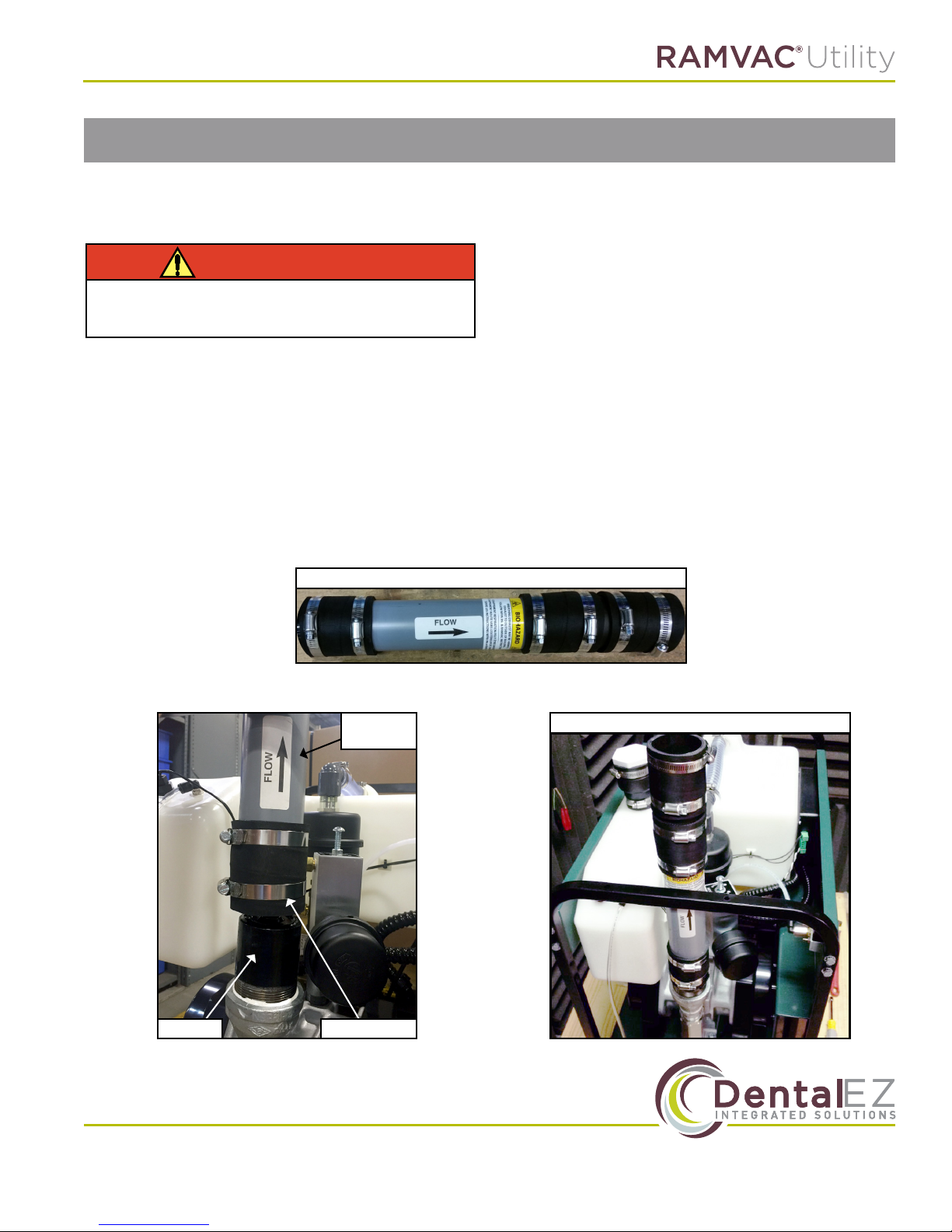
Muler Installation
Tools needed:
• 5/16” nut driver or athead screwdriver
WARNING
To prevent any chance of electrical shock,
always disconnect power when indicated.
1. To install the muler assembly, slide the assembly all the way down onto the pre-installed
silencer.
NOTE: Following the directional arrows making sure that the ow arrow is pointed upwards.
2. Use a 5/16” nut driver or athead screwdriver to tighten the bottom hose clamp so that the mufer is tightly seated onto the silencer.
Silencer
Muler
Assembly
Hose Clamp
Muler Assembly
Installed Muler
www.DentalEZ.com 866-DTE-INFO (opt 4)
www.DentalEZ.com
11
11
Page 13
Section II Installation
Badger LF User Manual
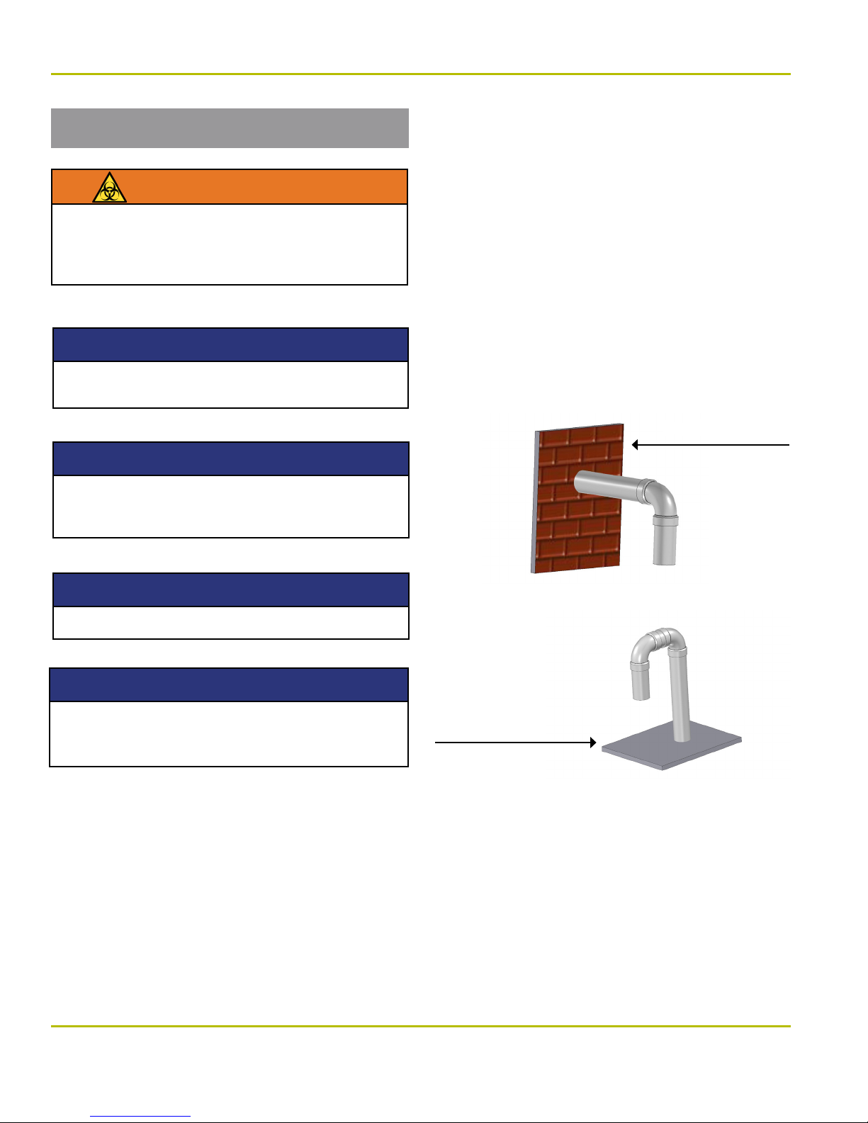
Exhaust Plumbing
BIOHAZARD
Breathing Dental Vacuum System Exhaust May
Be Harmful. Exhaust to Outside of Building.
Follow NFPA 99c, RAMVAC Instructions, and
local requirements.
NOTICE
Run Dedicated Exhaust Lines for each RAMVAC
unit installed. DO NOT connect to plumbing vents.
NOTICE
Support loosely. DO NOT allowing piping to
touch ductwork. DO NOT make solid attachments to building structure.
Pipe needed:
2” Sch 80 CPVC, or metal (NOT tar coated).
Outside End
(Installer supplied)
1. Turn outside end down toward ground and
screen to prevent entry of water, debris, and
creatures.
2. Locate inconspicuously for sight and sound.
3. Locate to prevent exhaust from entering
building.
Outside Wall
NOTICE
All joints MUST be glued with approved adhesive.
NOTICE
If exhaust noise is excessive, please contact
your authorized dealer or RAMVAC for
additional muler options.
Roof Line
www.DentalEZ.com
www.DentalEZ.com
12
12
866-DTE-INFO (opt 4)
Page 14
Section III Operation
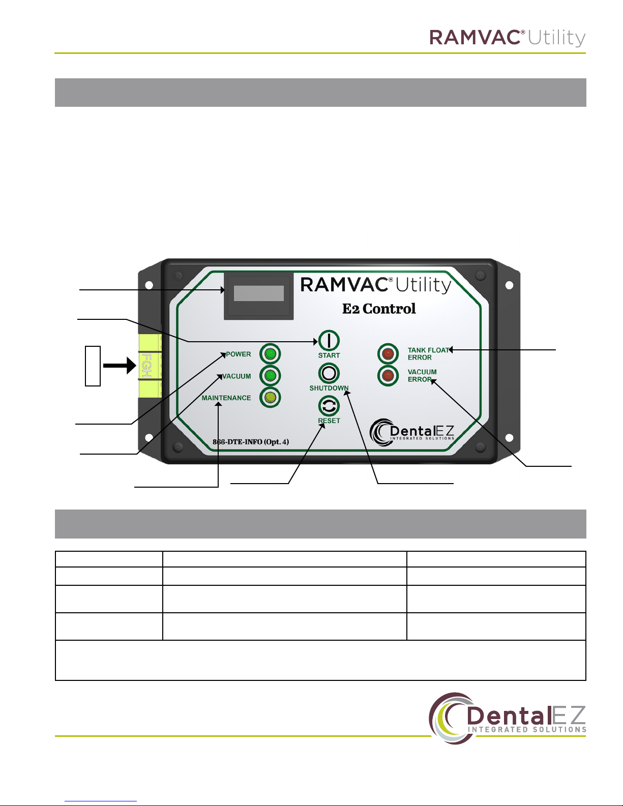
E2 Control Features
• Status Lights
• Power Status – Green light is on when line
voltage is present. Power Status light ashes
while unit is performing a shutdown cycle.
(See Shutdown Cycle Section)
• Vacuum Pump Status – Green light is on when
vacuum pump is running.
• Accepts the remote switch input.
Hour Meter
START/RUN
Button
F. G. H.
• Maintenance Light – Yellow light is on when
preventive maintenance is due.
• Provides 24v DC low voltage signal to the re-
mote switch panel
• Controls the tank draining sequence.
• Keeps track of run time hours.
• Error Lights display fault information.
Tank
Float
Error
Power Status
Vacuum
Pump Status
Maintenance Light
Reset Button
Shutdown Button
Vacuum
Pump
Error
E2 Faults
Faults: System Status: Corrective Action:
Maintenance System runs normally. “Maintenance” LED is illuminated. Perform “Preventive Maintenance”
Vacuum Pump Error
Tank Float Error
NOTE: An Error will cause the unit to shut down. This is to protect the system from damage. An Error Fault should only be
cleared after the cause of the fault has been identied and corrected. To clear an Error Fault, press and release the Reset
Button. The unit should automatically restart.
System will not run. Remote switch indicator ashes.
“Vacuum Pump Error” LED is illuminated on E2.
System will not run. Remote switch indicator ashes.
“Tank Float Error” LED is illuminated on E2.
See Troubleshooting Section
See Troubleshooting Section
www.DentalEZ.com 866-DTE-INFO (opt 4)
www.DentalEZ.com
13
13
Page 15
Section III Operation
Badger LF User Manual
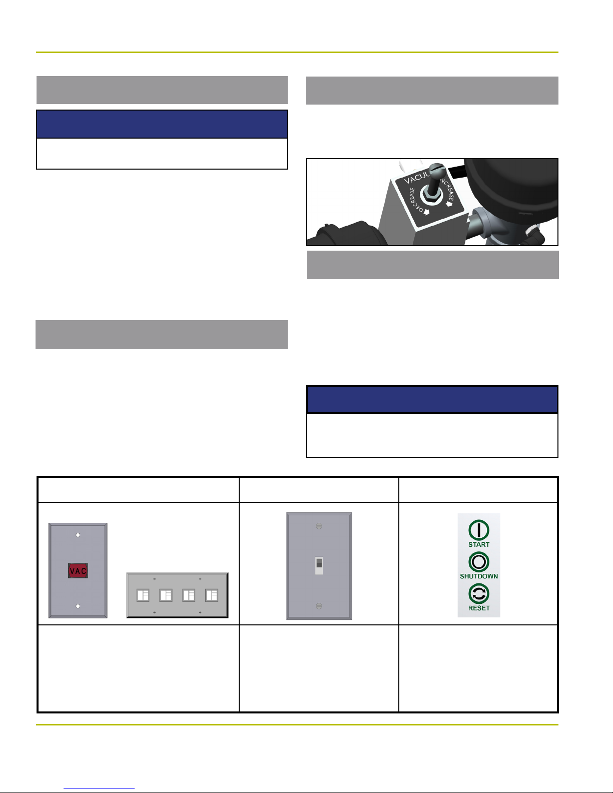
Turning the System On/O
NOTICE
Make sure all HVEs and saliva ejectors are
closed before turning the system o.
The RAMVAC can be run continuously throughout
the workday. Avoid wasting electricity by turning
o the RAMVAC if vacuum will not be needed for
an hour or more.
NOTE: No high voltage switching with the Badger LF.
NOTE: No special skills are required by the operator
to safely utilize this equipment. Contact the installing
dealer or RAMVAC if the following pages do not adequately answer all questions.
Shutdown Cycle
Turn the unit OFF at the end of each day. When
the unit is turned o, the power status light will
blink for 90 seconds, the tank will drain and the
Vacuum Pump will RESTART and run for a period
of 10 minutes. After this time has elapsed, the unit
will automatically turn o. This cycle is utilized to
prevent corrosion in the pump.
Vacuum Level
The vacuum level of the Badger LF is factory set
at 7 inch Hg (when all HVEs and SEs are closed).
Do not increase vacuum level above 12 inch Hg.
Separation Tank
The Badger LF contains an integrated separation
tank that will collect uids that are evacuated from
the operatory room. If the uid rises to an excessive
level within the tank, the Badger LF will disrupt vacuum for approximately 60 seconds in order for the
tank to drain. After this drain time has elapsed, the
unit will automatically restart and restore vacuum.
NOTICE
IMPORTANT: Fluids in the separation tank are
hazardous. The Badger’s drain must be properly
connected to the facility’s sewer plumbing.
Illuminated Remote Control Panel
Use this switch to turn system on and o
from a remote location.
• Switch light is steady-on when system is
running without “Fault”.·
• Switch light ashes if a “Fault” has occurred.
www.DentalEZ.com
www.DentalEZ.com
Non-Illuminated Remote Panel
Use this switch to turn system on
and o from a remote location.
• Non-illuminated switches provide
no indication for system status.
14
14
E2 Start/Run & Shutdown
Pushbuttons
Use this switch to turn system on
and o.
• If you have no remote switch.
• If you want to turn the system on
or o from the equipment’s location.
866-DTE-INFO (opt 4)
Page 16
Section IV Care
Maintenance Overview
WARNING
Prior to performing any maintenance, proper
precautions should be taken to reduce the possibility of contact with infectious substances.
Key points for trouble-free operation:
• Rinse vacuum lines daily with the recommend-
ed quantity of liquid and line cleaner.
• Check air lter on schedule.
• Exchange the pump head on schedule.
Preventative Maintenance Schedule
Daily - Rinse vacuum lines
See "Cleaning the Vacuum System"
Every 1,000 hours* - Inspect air lters
See "Changing the Air Filters"
Every 12,000 Hours* - Exchange pump head
See "Pump Head Exchange"
* The "Maintenance" LED on the E2 Control will
illuminate every 1,000 hours.
* To reset the "Maintenance" LED after
maintenance has been performed, press and
hold the "Reset" button for 10 seconds until the
"Maintenance" LED begins blinking.
After Surgical Procedures
1. Aspirate a few ounces of an appropriate vacuum line cleaner, such as SlugBuster
the lines.
TM
, through
For Overhead Plumbing
1. Be sure to allow air to follow liquids before
closing vacuum valves.
Cleaners
Cleaners should have these qualities:
• Non-foaming
• Deodorizing
• Sanitizing
• pH between 6 and 10
CAUTION
IMPORTANT: Use of line cleaners outside of
this pH range will void the warranty.
CAUTION
Foam may cause damage to the pump. Avoid
interruptions by insuring your cleaner is truly
“non-foaming”. Test by shaking the mixed
solution. True “non-foamers” will be bubble free.
NOTICE
Use of SlugBusterTM vacuum line cleaner is
highly recommended. SlugBuster is available
in powder and liquid forms, which can be ordered through any authorized RAMVAC dealer.
Cleaning the Vacuum System
NOTE: The Vacuum System should be cleaned daily.
NOTE: Check the treatment room solids separator
routinely and clean when dirty.
1. Just before turning o the RAMVAC, rinse vacuum lines rst with hot water - approximately
one quart through each high volume line and a
few ounces through each saliva ejector line.
2. Aspirate a few ounces of a dental vacuum line
cleaner through each vacuum line.
SlugBusterTM is highly recommended.
www.DentalEZ.com 866-DTE-INFO (opt 4)
www.DentalEZ.com
15
15
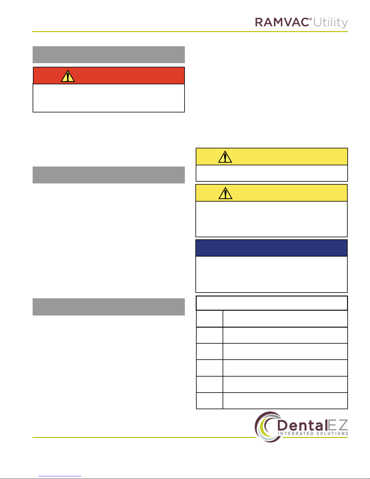
SlugBuster Ordering Information
RAMVAC
Part No.
900143
900146
900241
900243
900246
Powder Starter Pack: Mixing jug, two 40 oz.
containers of SlugBuster.
Powder 6 Pack: six 40 oz. containers of
SlugBuster (makes 480 gallons of solution)
Liquid Single Gallon: 1 gallon of SlugBuster
concentrate and hand pump dispenser
Liquid Starter Pack: Mixing jug, 1 gallon of SlugBuster concentrate and hand pump dispenser
Liquid 4 Pack Case: 4 single gallons of SlugBuster
concentrate and 4 hand pump dispensers
Contents
Page 17
Section IV Care
Badger LF User Manual
Cleaning the Vacuum Unit
CAUTION
Some parts/components on the
vacuum unit get hot during operation.
Provide the equipment ample time to
cool prior to cleaning.
NOTE: The Vacuum Unit should be cleaned every
1,000 hours.
1. Always disconnect the power from the
equipment prior to cleaning.
2. All components can be safely wiped down
with a damp cloth, wet with water. We do
not recommend using any cleaners or harsh
chemicals to clean this equipment since their
potentially harmful eects have not been
evaluated.
3. Do not heavily wet electrical components
4. Allow equipment to air dry or dry with a clean,
soft cloth.
Pump Head Exchange
NOTICE
A detailed instruction sheet will be sent with
the replacement pump.
NOTE: Inspect pump head every 1,000 hours.
Check Poly V-Belt
CAUTION
Disconnect power before any service to avoid
injury during dry down cycle. E2 can start
machine if still powered. Keep hands away
from moving parts.
NOTE: Inspect belt every 2,000 hours. Replace if
cracked or frayed.
Changing Air Filters
NOTE: Inspect air lters every 1000 hours.
1. The Air Filter is accessed by twisting the
end cap on the Air Filter Housing in a counter-clockwise motion.
2. Replace lters every 2,000 hours or when
visibly dirty.
www.DentalEZ.com
www.DentalEZ.com
866-DTE-INFO (opt 4)
16
16
Page 18
Section V User Service Information
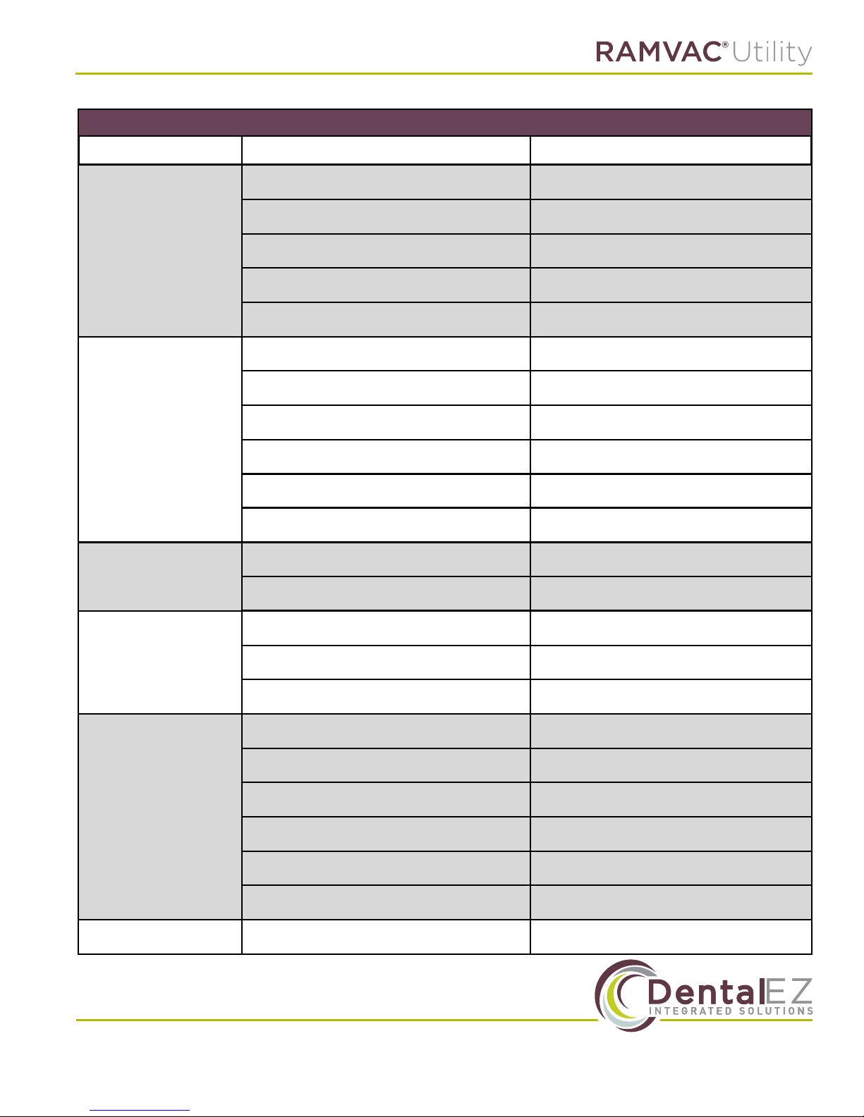
TROUBLESHOOTING
Symptom Possible Cause(s) Corrective Action
Tank drain check valve blocked open Clean tank drain check valve
Clogged vacuum line Locate and remove clog
Low or No Vacuum
(motor running okay)
Motor Does Not Run
Liquid Comes
Out Exhaust
Vacuum controller stuck open Repair and replace vacuum controller
Vacuum leaks Locate and x leak
Worn or broken vanes Exchange pump head
"Tripped" breaker Reset breaker
"Tripped" motor overload Reset motor overload
Motor failure Replace Motor
Failed control component Replace failed component
"Vacuum Pump Error" fault See "Vacuum Pump Error" fault below
"Tank Float Error" fault See "Tank Float Error" fault below
Unit unleveled Level unit
Foam in tank Use non-foaming line cleaner
Incorrect electrical installation Correct installation
"Vacuum Pump Error"
Fault
Motor failure Replace motor
"Tripped" motor overload Reset motor overload
Separating tank overlled Drain separation tank
Separation tank drain check valve stuck Clean separation tank drain check valve
"Tank Float Error"
Fault
Clogged drain line Locate and remove clog
Drain shut-o valve closed Open drain shut-o valve
Tank oat switch stuck Replace tank oat switch
Facility drain elevated above tank drain Raise unit
Maintenance Required Preventative maintenance due Perform preventative maintenance
www.DentalEZ.com 866-DTE-INFO (opt 4)
www.DentalEZ.com
17
17
Page 19
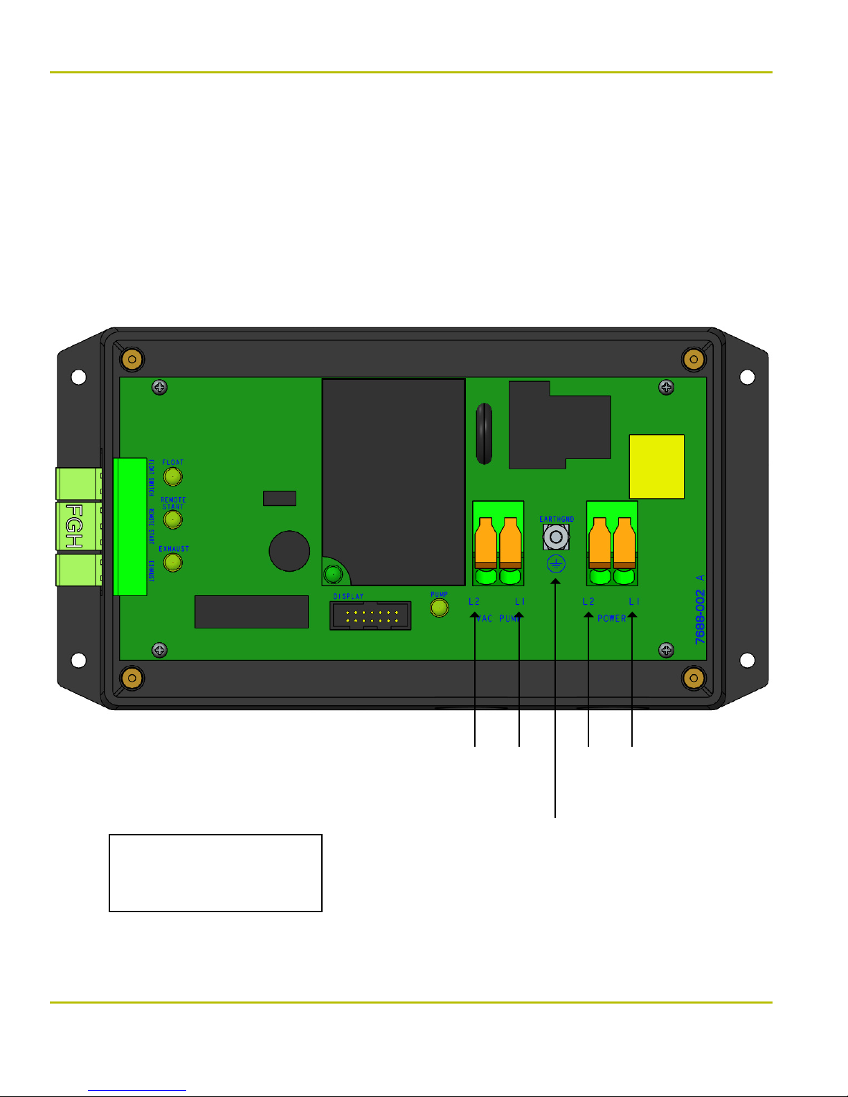
Section VI Electrical Connections
Badger LF User Manual
L1 - BLACK
L2 - RED
GROUND - GREEN/YELLOW
www.DentalEZ.com
www.DentalEZ.com
18
18
L2 L1 L2 L1
Vacuum
Motor
Ground
Power
(230v 1 phase)
866-DTE-INFO (opt 4)
Page 20
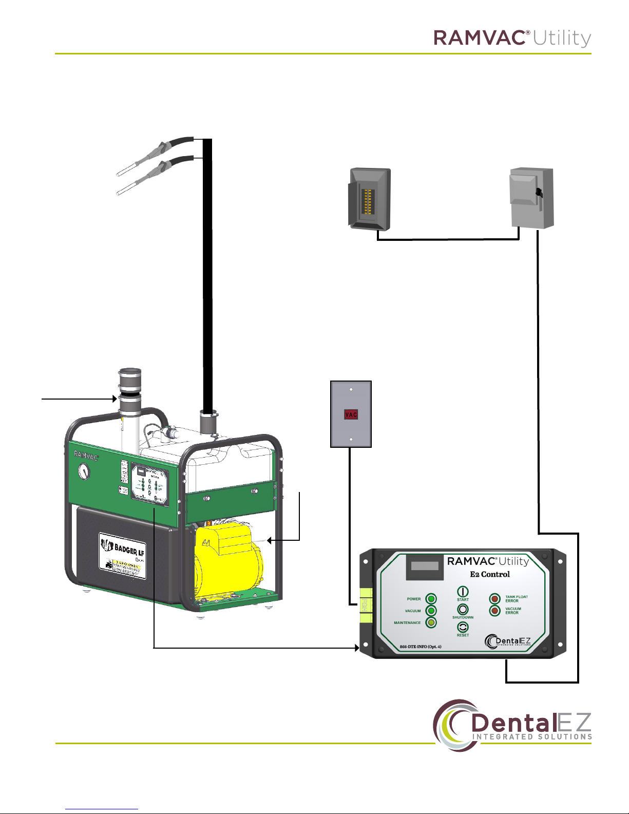
Section VII System Schematics
Vacuum
devices
2” Dedicated
Exhaust
to outside
Facility
Plumbing
Breaker
Remote
Switch
Box
Disconnect
Tank
Drain
3 conductors
Low Voltage Wires
www.DentalEZ.com 866-DTE-INFO (opt 4)
www.DentalEZ.com
19
19
Page 21
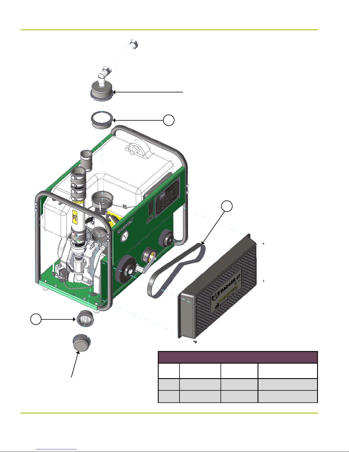
Section VIII Parts List/Diagrams
Badger LF User Manual
Rotate clockwise and
lift to access lter
2
2
Rotate clockwise and
lift to access lter
1
Regular Maintenance Kit
# Part/Kit Name Part /Kit No.
1 Belt 39" 8801-003 Every 5 Years
2 Filter Set 005301SP Yearly
Recommended
Maintenance Interval
www.DentalEZ.com
www.DentalEZ.com
20
20
866-DTE-INFO (opt 4)
Page 22
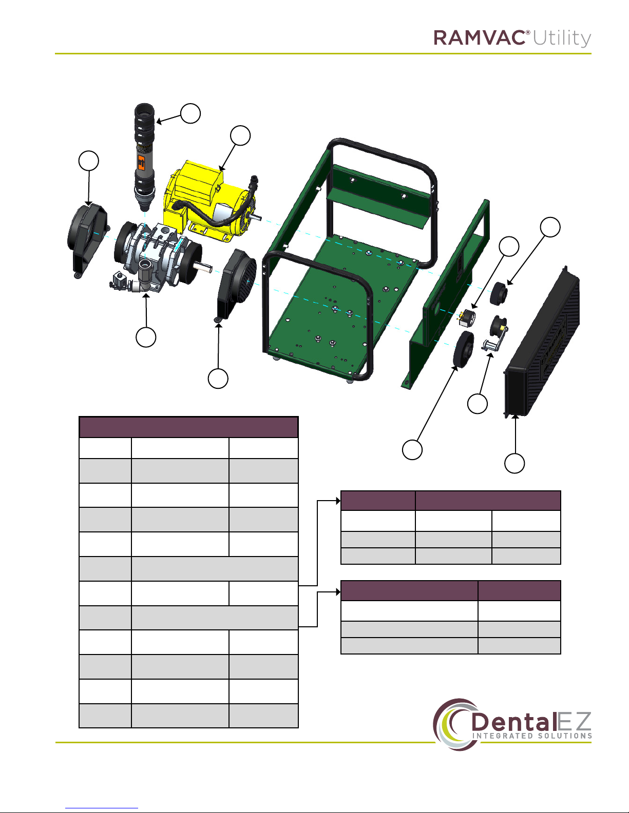
Section VIII Parts List/Diagrams
10
9
8
4
3
7
6
Mechanical Replacement Parts Kits
# Part /Kit Name Part/Kit No.
1 Belt Guard Kit 8801-007
2
3 Vacuum Gauge Kit 004617SP
4 Motor Pulley Kit 8801-009
5 See chart to right
6
7 See chart to right
8
Belt Tensioner
Assy Kit
Front Pump Fan
Cover Kit
Rear Pump Fan
Cover Kit
8801-008
8801-012
8801-013
2
5
1
5
Model No. Part/Kit Name Part/Kit No.
Badger LF1 Pulley, 5" 8801-010
Badger LF2 Pulley, 4" 8801-011
7
Part/Kit Name Part/Kit No.
NEW Pump Kit 8801-006
Re-manufactured Pump Kit 8801-006RM
Pump
Pump Kit
9 Motor Kit 8801-014
10 Muler Kit 8801-029
RAMVAC Green
Touch-up Paint
www.DentalEZ.com 866-DTE-INFO (opt 4)
www.DentalEZ.com
004288
21
21
Page 23
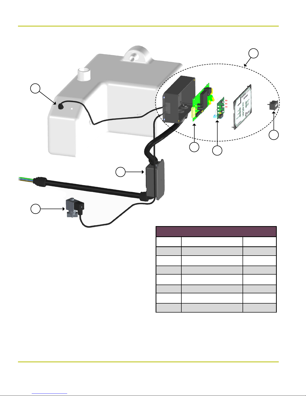
Section VIII Parts List/Diagrams
1
Badger LF User Manual
2
5
3
7
6
4
Electrical Replacement Parts Kits
# Part /Kit Name Part/Kit No.
1 Tank Float Kit 004612SP
2 Complete E2 Control Kit 8801-019
3 E2 Control Board Kit 8801-015
4 E2 LED Display Kit 8801-016
5 E2 Hour Meter 8801-020
www.DentalEZ.com
www.DentalEZ.com
22
22
6 Solenoid Valve Kit 8801-018
7 Power Harness Kit 8801-017
866-DTE-INFO (opt 4)
Page 24
Limited Warranty
Badger LF
DentalEZ and its employees are proud of the products we provide to the dental community. We stand behind these products
with a warranty against defects in material and workmanship as provided below and have our own in-house repair facility to
service our products.
In the event that you experience diiculty with the application or operation of any of our products, please contact our customer service department at our expense at (866) DTE-INFO.
If we cannot resolve the issue by telephone, we will arrange for a representative to contact you or suggest that the product
be returned to our factory for inspection.
If product return or repair is required, we will provide you with a Return Authorization number and shipping instructions to
return the product to the proper facility. If the product is under warranty, we will ask you to provide proof of purchase, such
as a copy of your invoice. Please be sure to include the Return Authorization number on the package you are returning.
Products returned without a Return Authorization number cannot be repaired.
Freight costs for product returns are the responsibility of the customer. Products under warranty will be repaired or re-
placed, at our sole discretion, and returned at our expense. Products outside the warranty limits will be repaired and returned
with costs invoiced to the customer. We are not responsible for shipping damages. We will, however, help you le a claim with
the freight carrier. Written repair estimates are available.
DentalEZ warrants the Badger LF to be free of defects in material and workmanship, under normal usage under the following terms.
Warranty Period
2 years or 4,000 hours (whichever comes rst) for the Dental Vacuum System excluding normal wear parts, which
includes all lters and belts.
5 years or 10,000 hours (whichever comes rst) for the vacuum pump only.
Please note the following additional terms of our warranty and return policy:
• Warranties cover manufacturing defects only and do not cover defects resulting from abuse, improper handling,
cleaning, care or maintenance, normal wear and tear or non-observance of operating, maintenance or installation
instructions. Failure to use authorized parts or an authorized repair facility voids this warranty.
• Liability is limited to repair or replacement of the defective product at our sole discretion. All other liabilities, in
particular liability for damages, including, without limitation, consequential or incidental damages are excluded.
• THIS WARRANTY IS IN LIEU OF ALL OTHER WARRANTIES, EXPRESSED OR IMPLIED, INCLUDING ANY IMPLIED WARRANTIES OF MERCHANTABILITY OR FITNESS FOR A PARTICULAR PURPOSE. NO EMPLOYEE, REPRESENTATIVE OR DEALER
IS AUTHORIZED TO CHANGE THIS WARRANTY IN ANY WAY OR TO GRANT ANY OTHER WARRANTY.
WARRANTY REPAIRS: Parts repaired or replaced on a product that is in warranty will be warranted for the duration of that
product’s original warranty.
NON-WARRANTY REPAIRS: The warranty on parts either repaired or replaced on an out-of-warranty product will cover the
repaired part only and will be for the time frame of a new parts warranty period.
PRODUCT RETURN: Opened products or product returns more than a year old cannot be returned for credit. There will be a
15% ($25.00 minimum) restocking charge on all items authorized for return.
*Provided conditions dened in the User Manual are met.
DentalEZ and RAMVAC are registered trademarks of DentalEZ, Inc. SlugBuster is a trademark of RAMVAC Dental Products, Inc.
© 2017 DentalEZ Alabama, Inc.
www.DentalEZ.com 866-DTE-INFO (opt 4)
www.DentalEZ.com
23
23
Page 25
EMC Information
Badger LF User Manual
Medical Electrical Equipment needs special precautions regarding EMC and needs to be installed and put into service
according to the EMC information provided in this manual.
Portable and mobile RF communications equipment can aect Medical Electrical Equipment.
The use of Accessories, transducers, and cables other than those specied, with the exception of transducers and cables
sold by the Manufacturer of this device as replacement parts for internal components, may result in increased Emissions or
decreased Immunity of the RAMVAC Badger LF.
The RAMVAC Badger LF should not be used adjacent to or stacked with other equipment and that if adjacent or stacked use is
necessary, the RAMVAC Badger LF should be observed to verify normal operation in the conguration in which it will be used.
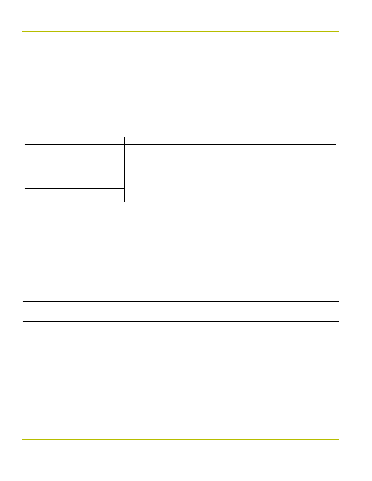
GUIDANCE AND MANUFACTURER’S DECLARATION – ELECTROMAGNETIC EMISSIONS
The Badger LF is intended for use in the electromagnetic environment specied below. The customer or the user of the
Badger LF should assure that it is used in such an environment.
Emissions test Compliance Electromagnetic environment – guidance
RF emissions
CISPR 11
RF emissions
CISPR 11
Harmonic emissions
IEC 61000-3-2
Voltage uctuations / icker
emissions IEC 61000-3-3
Group 1
Class A
Not Applicable
Not Applicable
The Badger LF uses RF energy only for its internal function. Therefore, its RF emissions are very low and
are not likely to cause any interference in nearby electronic equipment.
The Badger LF is suitable for use in all establishments other than domestic and those directly connected to the public low-voltage power supply network that supplies buildings used for domestic purposes.
GUIDANCE AND MANUFACTURER’S DECLARATION – ELECTROMAGNETIC IMMUNITY
The Badger LF is intended for use in the electromagnetic environment specied below. The customer or the user of the
Badger LF should assure that it is used in such an environment.
Immunity test IEC 60601 test level Compliance level
Electrostatic
discharge (ESD)
IEC 61000-4-2
Electrical fast transient/burst
IEC 61000-4-4
Surge
IEC 61000-4-5
Voltage dips, short
interruptions and
voltage variations on
power supply input
lines IEC 61000-4-11
±6 kV contact
±8 kV air
±2 kV for power supply lines
±1 kV for input/output lines
±1 kV line(s) to line(s)
±2 kV line(s) to earth
<5 % UT
(>95 % dip in UT)
for 0,5 cycle
40 % UT
(60 % dip in UT)
for 5 cycles
70 % UT
(30 % dip in UT)
for 25 cycles
<5 % UT
(>95 % dip in UT)
for 5 sec
± 6 kV Contact
± 8 kV Air
± 2 kV for power supply lines
Not Applicable for input/output lines
±1 kV line(s) to line(s)
±2 kV line(s) to earth
Not Applicable
Floors should be wood, concrete or ceramic tile.
If oors are covered with synthetic material, the
relative humidity should be at least 30 %.
Mains power quality should be that of a typical
commercial or hospital environment.
Mains power quality should be that of a typical
commercial or hospital environment.
Mains power quality should be that of a typical
commercial or hospital environment. If the user of
the Badger LF requires continued operation during
power mains interruptions, it is recommended that
the Badger LF be powered from an uninterruptible
power supply or a battery.
Electromagnetic environment –
guidance
Power frequency
(50/60 Hz) magnetic
eld IEC 61000-4-8
NOTE UT is the a.c. mains voltage prior to application of the test level.
www.DentalEZ.com
www.DentalEZ.com
3 A / m
3 A/m
24
24
Power frequency magnetic elds should be at levels
characteristic of a typical location in a typical commercial or hospital environment.
866-DTE-INFO (opt 4)
Page 26
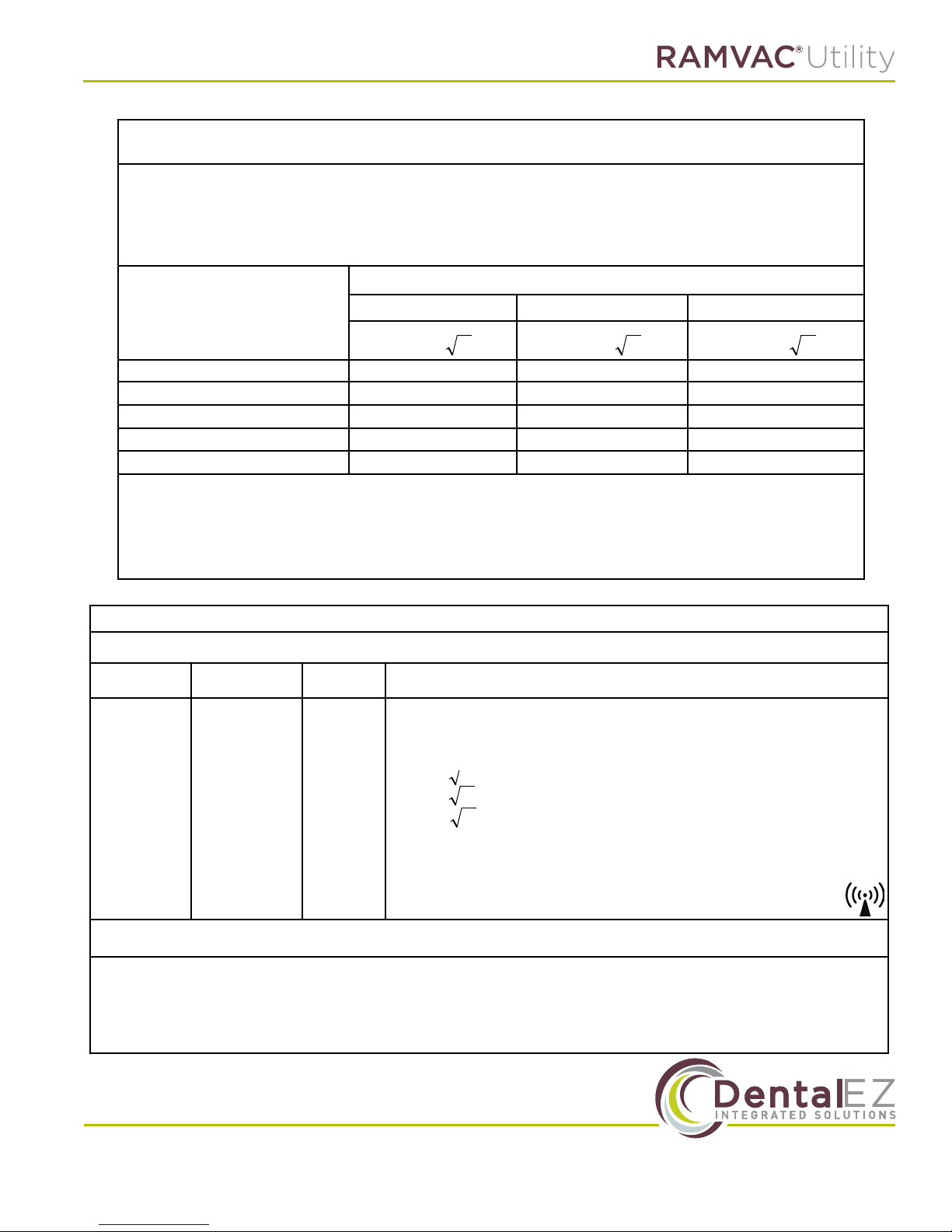
Pd 2.1=
Pd 2.1=
Pd 3.2=
Pd 2.1=
Pd 2.1=
Pd 3.2=
EMC Information
Recommended separation distances
between portable and mobile RF communications equipment and the Badger LF
The Badger LF is intended for use in an electromagnetic environment in which radiated RF disturbances are
controlled.
The customer or the user of the Badger LF can help prevent electromagnetic interference by maintaining a minimum distance between portable and mobile RF communications equipment (transmitters) and the Badger LF as
recommended below,
according to the maximum output power of the communications equipment.
Rated maximum output power
of transmitter
W
0,01 0.12 0.12 0.23
0,1 0.38 0.38 0.73
1 1.20 1.20 2.30
10 3.79 3.79 7. 27
100 12.00 12.00 23.00
For transmitters rated at a maximum output power not listed above, the recommended separation distance d in meters (m) can be estimated
using the equation applicable to the frequency of the transmitter, where P is the maximum output power rating of the transmitter in watts (W)
according to the transmitter manufacturer.
NOTE 1 At 80 MHz and 800 MHz, the separation distance for the higher frequency range applies.
NOTE 2 These guidelines may not apply in all situations. Electromagnetic propagation is aected by absorption and reection from structures, objects and people.
150 kHz to 80 MHz 80 MHz to 800 MHz 800 MHz to 2,5 GHz
Separation distance according to frequency of transmitter m
GUIDANCE AND MANUFACTURER’S DECLARATION – ELECTROMAGNETIC IMMUNITY
The Badger LF is intended for use in the electromagnetic environment specied below. The customer or the user of the Badger LF should assure that
it is used in such an environment.
Immunity test
Conducted RF
IEC 61000-4-6
Radiated RF
IEC 61000-4-3
NOTE 1 At 80 MHz and 800 MHz, the higher frequency range applies.
NOTE 2 These guidelines may not apply in all situations. Electromagnetic propagation is aected by absorption and reection from structures, objects and people.
a Field strengths from xed transmitters, such as base stations for radio (cellular/cordless) telephones and land mobile radios, amateur radio, AM
and FM radio broadcast and TV broadcast cannot be predicted theoretically with accuracy. To assess the electromagnetic environment due to
xed RF transmitters, an electromagnetic site survey should be considered. If the measured eld strength in the location in which the Badger LF is
used exceeds the applicable RF compliance level above, the Badger LF should be observed to verify normal operation. If abnormal performance is
observed, additional measures may be necessary, such as re-orienting or relocating the Badger LF.
b Over the frequency range 150 kHz to 80 MHz, eld strengths should be less than 3 V/m.
IEC 60601 test
level
3 Vrms
150 kHz to 80
MHz
3 V/m
80 MHz to 2,5
GHz
Compliance
level
3 Vrms
3 V/m
Electromagnetic environment – guidance
Portable and mobile RF communications equipment should be used no closer to any part of
the Badger LF, including cables, than the recommended separation distance calculated from
the equation applicable to the frequency of the transmitter.
Recommended separation distance
80 MHz to 800 MHz
800 MHz to 2,5 GHz
where P is the maximum output power rating of the transmitter in watts (W) according to the
transmitter manufacturer and d is the recommended separation distance in meters (m).
Field strengths from xed RF transmitters, as determined by an electromagnetic site survey,
a
should be less than the compliance level in each frequency range.b
Interference may occur in the vicinity of equipment marked with the following symbol:
www.DentalEZ.com 866-DTE-INFO (opt 4)
www.DentalEZ.com
25
25
Page 27

© DentalEZ® Alabama, Inc.
Printed in USA
2500 Highway 31 South
Bay Minette, Alabama 36507
866-DTE-INFO (opt 4)
www.dentalez.com
PN: 7717-001C
August, 2017
 Loading...