

Ramsey Winch 400, Y-400, GY-400, H-400, HY-400 Operating, Service And Maintenance Manual
...Page 1

OPERATING, SERVICE,
AND MAINTENANCE
MANUAL
MODEL 400 SERIES
MODEL H-400 SERIES
LEVER EQUIPPED
INDUSTRIAL LOW-MOUNT
WINCHES
INCLUDES 400/Y-400, H-400/HY-400, AND
MODELS EQUIPPED WITH OPTIONAL
ADJUSTABLE, AUTOMATIC, OIL COOLED
SAFETY BRAKE: G-400/GY-400,HG-400/HGY-400
CAUTI0N: READ AND UNDERSTAND THIS MANUAL BEFORE INSTALLATION
AND OPERATION OF WINCH. SEE SAFEGUARDS AND WARNINGS!
912410-0615-O-H400 SERIES
Page 2

Page 3

TABLE OF CONTENTS
INTRODUCTION ……………………………………………………. 1
WARRANTY INFORMATION ……………………………………………………. 1
SPECIFICATION ……………………………………………………. 1
TECHNIQUES OF OPERATION ……………………………………………………. 2
SAFEGUARDS: WARNING ……………………………………………………. 2
WINCH MAINTENANCE ……………………………………………………. 3
WINCH MOUNTING ……………………………………………………. 4
CABLE INSTALLATION ……………………………………………………. 4
ADJUSTING THE OIL COOLED SAFETY BRAKE ……………………………………………………. 4
SERVICING OF THE OIL COOLED
SAFETY BRAKE ……………………………………………………. 5
RE-ASSEMBLING AND CHECKING THE BRAKE ……………………………………………………. 6
TEST FOR PROPER BRAKE ASSEMBLY ……………………………………………………. 6
INSTRUCTIONS FOR CHECKING ASSEMBLY ……………………………………………………. 7
ARRANGEMENT AND SETTING OF WORM BRAKE
HYDRAULIC SYSTEMS/PERFORMANCE CHARTS ……………………………………………………. 8
TYPICAL LAYOUT/HYD. SYSTEM DIAGRAM ……………………………………………………. 9
TROUBLE SHOOTING TIPS ……………………………………………………. 9
INSTRU
CTIONS FOR OVERHAUL OF
RAMSEY MODEL 400/H-400 SERIES LEVER STYLE WINCHES
DISASSEMBLY ……………………………………………………. 10-13
RE-ASSEMBLY ……………………………………………………. 13-15
DIMENSIONAL DRAWING ……………………………………………………. 16-18
PARTS LIST AND PARTS DRAWING ……………………………………………………. 19-25
LIMITED WARRANTY ……………………………………………………. 26
3
Page 4

INTRODUCTION
Rated Line Pull 1s t layer (lbs.)...........................10,000
(Kgs.)...........................4,530
Shipping Weight: 400/Y-400 ....................125 lbs . (57 Kgs ..)
G-400/GY-400.................135 lbs . (61 Kgs.)
H-400/HY-400 .........
......150 lbs . (68 Kgs .)
HG-400/HGY-400 ..............160 lbs. {73 Kgs.)
2 3 4
Rated Line Pull per
layer for
400/G-400 Lbs . 8,200 6,900 6,000
H-400/HG-400 Kgs. 3,710 3,120 2,710
Rated Line Pull per
layer for
**
Y-400/GY-400 Lbs . 8,300 7,100 6,200
HY-400/HGY-400 Kgs. 3,760 3,210 2,800
*Long Drum
**
Cable capacity per Ft. 55 90 130
layer for 400/G-400 M. 1 6 27 39
H-400/HG-400
*Short "Y" Drum Cable
capacity per layer
Y-400/GY-400 Ft. 45 70 105
HY-400/HGY-400 M. 13 21 31
Worm
RPM 1 2 3 4
400/G-400 FPM 33 40 47 53
H-400/HG-400 MPM
840
10 12 14 16
Y-400/GY-400 FPM 34 40 47
54
**
HY-400/HGY-400 MPM 840 10.5 12.3 14.5 16.6
*Thes e specifications are bas ed on recommended cab le of 7/16" (11m m ) 6x19 extra
improved plow steel cab le.
**Lost Ioyer does not conform to SAE
J706
Line Speed
20
6
25
7
10,000
4,530
10,000
4,530
Layer of Cable 1
SPECIFICATIONS: CONFORMS TO SAE J706
Gear Reduction: 400/H-400............................................................................................29:1
PLEASE READ THIS MANUAL CAREFULLY.
This manual contains useful ideas in obtaining the most effi cient operation from your
Ramsey Winch, and safety procedures one needs to know before operating a Ramsey
Winch.
WARRANTY INFORMATION
Ramsey Winches are designed and built to exacting specifi cations. Great care and skill
go into every winch we make. If the need should arise, warranty procedure is outlined on
the back of your self-addressed postage paid warranty card. Please read and fi ll out the
enclosed warranty card and send it to Ramsey Winch Company. If you have any problems
with your winch, please follow instructions for prompt service on all warranty claims. Refer
to back page for limited warranty.
NOTE: The rated line pulls shown are for the winch only. Consult the wire rope manufacturer for
wire rope ratings.
4
Page 5

TECHNIQUES OF OPERATION
The best way to get acquainted with how your winch operates is to make test runs before you
actually use it. Plan your test in advance. Remember, you hear your winch, as
well as see it operate. Set to recognize the sounds of a light steady pull, a heavy pull, and
sounds caused by load jerking or shifting. Gain confi dence in operating your winch and its use
will become second nature with you.
The uneven spooling of cable, while pulling a load, is not a problem, unless there is a cable
pileup on one end of drum. If this happens,reverse the winch to relieve the load and move your
anchor point further to the center of the vehicle. After the job is done you can unspool and rewind
for a neat lay of the cable.
The winch clutch allows rapid unspooling of the cable, from cable drum, for hooking onto a load.
The clutch is operated by the handle located on the clutch housing of winch.
1. TO DISENGAGE CLUTCH, run winch in the reverse (reel out) direction until the load is off the
cable. Grasp the clutch handle and move it toward the cable drum to the "OUT" position. The
cable may now be pulled from the cable drum by hand.
2. TO ENGAGE CLUTCH, move the clutch handle away from the cable drum to the "IN" position,
while slowly running the winch in the forward (reel in) direction, until the clutch jaws move into
engagement with the drum jaws. When the cable drum starts rotating, stop and make sure
that the clutch is engaged and that the clutch handle is fully at the "IN" position. CLUTCH
MUST BE TOTALLY ENGAGED DURING WINCHING OPERATIONS. The winch is now
ready for pulling in the load.
SAFEGUARDS-WARNINGS:
CLUTCH MUST BE TOTALLY ENGAGED BEFORE STARTING THE WINCH.
DO NOT DISENGAGE CLUTCH UNDER LOAD.
DO NOT LEAVE CLUTCH ENGAGED WHEN WINCH IS NOT IN USE. STAY OUT FROM UNDER AND AWAY FROM RAISED LOADS.
STAND CLEAR OF CABLE WHILE PULLING. DO NOT TRY TO GUIDE CABLE.
DO NOT EXCEED MAXIMUM LINE PULL RATINGS SHOWN IN TABLE.
DO NOT USE WINCH TO LIFT, SUPPORT, OR OTHERWISE TRANSPORT PERSONNEL.
A MINIMUM OF 5 WRAPS OF CABLE AROUND THE DRUM BARREL IS NECESSARY TO
HOLD THE LOAD. CABLE CLAMP IS NOT DESIGNED TO HOLD LOAD.
5
Page 6

WINCH MAINTENANCE
Adhering to the following maintenance schedule will keep your winch in top condit ion and performing
as it should with a minimum of repair.
A. WEEKLY
1. Check the oil level and maintain it to the oil level plug. If oil is leaking out, determine location and
repair.
2. Check the pressure relief plug in top of the gear housing. Be sure that it is in good operating condi tion so that hot oil gasses may escape.
3. Lubricate cable with light oil..
B. MONTHLY
1. Lubricate the various grease fi ttings located in the cable drum, end bearing, clutch housing or
clutch operating linkage. Any good grade of moly-disulfi de containing grease is acceptable.
2. In the case of jaw clutch winches check the action of the sliding clutch, making sure it is fully en gaging and disengaging with the cable drum. Observe the jaws on both the clutch and cable
drum, checking for rounding of the driving faces. If rounding has occurred they should be
replaced immediately.
3. In the case•of Dow-Lok clutches,check the action of the locking ring. Make sure it is spring
loaded and free to move fully against the cable drum in the engaged position and that it is pulled
fully away from the cable drum and latched when disengaged.
4. Check the winch mounting bolts. If any are missing, replace them and securely tighten any
that are loose. Make sure to use only grade 5 bolts or better.
5. Check the torque setting of the oil cooled worm brake. Make any adjust ments required, following
the procedure described in ADJUSTING THE OIL COOLED WORM BRAKE in the Owner's
Manual.
6. Check alignment of chain and sprockets and adjust as required to minimize wear.
7. Inspect the cable. If the cable has become frayed with broken strands, replace immediately.
C. ANNUALLY
1. Drain the oil from the winch annually or more often if winch is used frequently.
2. Fill the winch to the oil level plug with clean kerosene. Run the winch a few minutes with no
load in the reel in direction. Drain the kerosene from the winch.
3. Refi ll the winch to the oil level plug with all purpose E.P. 140 gear oil.
4. Inspeet frame and surrounding structure for cracks or deformation.
5. Gear wear can be estimated by rocking the drum back and forth and if necessary drain oil and
remove cover for closer inspection.
6
Page 7

WINCH MOUNTING
NUT
CAP
TUBING
INPUT SHAFT
(WORM)
ADAPTER
SOCKET
It is most important that this winch be mounted securely so that the three major sections (the clutch
housing end, the cable drum and the gear housing end) are properly aligned.
All standard model 400/H-400 Series Winches are furnished with recommended mounting angles.
Angle size is 3/8 x 2-l/2 x 3 x 36" Lg. high strength (36,000 PSI min. yield) steel angle.
CABLE INSTALLATION
1. Unwind cable by rolling it out along the ground to prevent kinking. Securely wrap end of cable,
opposite hook, with plastic or similar tape to prevent fraying.
2. Insert the end of cable, opposite hook end, into the l/2" dia. hole in drum barrel. Secure cable to
drum barrel, using setscrew furnished with winch. TIGHTEN SETSCREW SECURELY.
3. Carefully run winch in the "reel-in'' direction. Keeping tension on end of cable, spool all the cable
onto the cable drum, taking care to form neatly wrapped layers.
ADJUSTING THE OIL COOLED WORM BRAKE
The oil-cooled, fully adjustable, automatic safety brake operates in the worm housing lubricant, all
parts being submerged in oil. When the brake wears to the point that the load begins to drift, the
brake can be adjusted as follows:
1. Loosen the lock nut on the adjusting screw.
2. Tighten the brake by turning the adjusting screw clockwise. CAUTION: Only 1/4 turn is usu ally required to adjust the brake. Over-tightening can cause over heating, and damage to the
brake parts. Tighten the lock nut after adjustment is completed.
If the brake does not respond to adjustment then a new leaf spring and brake disc is needed.
A torque wrench can be equipped with a special adapter to fi t the input shaft (worm) of the winch.
The adapter can be made by welding a nut to the end of a piece of tubing as shown in the following
fi gure.
7
Page 8

SERVICING OF THE OIL
COOLED SAFETY BRAKE
1. Remove the drain plug and drain the worm gear oil from the worm housing.
2. Back off the lock nut,.then the adjusting screw, both two turns or more by turning them counter- clockwise.
3. Remove the cover mounting screws.
4. Remove the cover along with coil spring and leaf spring.
5. Remove the retainer plate, composition brake disc, cam plate and balls. Note slots balls are in.
6. Inspect parts as follows:
a). Composition brake discs are 1/4" thick when new. Replace if thinner than 3/16 or if surfaces
are glazed or burnt.
b). Inspect the fl at, ground surface of the cam plate and retainer plate for glazing, warpage, or
other damage. Glazing can be removed by scraping carefully.
c). Inspect the leaf spring. It should be bowed 1/8".
8
Page 9

RE-ASSEMBLING AND CHECKING THE BRAKE
1. Press brake hub into place over worm shaft and key.
2. Assemble ball into appropriate slots of cam. (Refer to diagram 1, pages). Use stiff grease to hold
balls into place and slide cam over end of worm. Be sure that balls are secure, between cam slots
and hub slots. Refer to Page 7 to determine proper ball slot setting.
3. Install brake disc.
4. Install retainer plate, smooth side toward brake disc.
5. Install the gasket on the cover with a small amount of grease or sealer.
6. The coil spring goes over the adjusting screw on the inside of the cover.
7. Install the notches of the leaf spring on the pins protruding through the cover. The hollow side of
the leaf spring goes toward the brake.
8. Install brake housing cover, making sure the protruding pins go through the leaf spring and into the
holes in the retainer plate.
9. Bolt cover into place with the mounting screws. Install drain plug and add 1-3/4 pint all purpose
E.P. 140 oil.
10. Turn winch in the hoisting direction at least one turn of the input shaft.
11. Turn the adjusting screw in until it is fi nger tight.
TEST FOR PROPER BRAKE ASSEMBLY
After the brake has been adjusted to the proper torque setting disengage clutch. Start vehicle engine
and run winch in the reel in (hoisting direction). Allow winch to run in this direction for one minute.
Place your hand on the safety brake housing. If housing is not hot to the touch then run winch in the
reverse direction (cable out) for one minute. Brake housing should begin to heat.
When these conditions exist, proper installation has been made. If heating becomes noticeable when
running the winch in forward rotation (hoisting direction), the brake should be again disassembled.
When disassembled, place the brake balls in the alternate set of slots in the cam plate, then carefully
follow the instructions for re-assembling and checking the brake.
9
Page 10

CHECKING ASSEMBLY ARRANGEMENT AND
SETTING OF WORM BRAKE
When the worm brake is assembled the brake must be set with the balls in the #1 or the #2 set of
cam slots. (View A-A, page 5). It is indicated on the name plate whether the balls were installed in the
#1 or the #2 slots at the factory.
Three factors determine which slots the balls should be in:
1. Direction cable winds on the drum. It normally WINDS OVER THE ROPE of the drum barrel.
2. The cut of the gear set, right or left gear. The last letter in the model number of the winch, either
R or L, designates right or left gear set. Example: R-20Ag, R-30 ,700B, 8001.
3. The side of the winch that the input shaft is on. The INPUT SHAFT IS NORMALLY TOWARD THE
CAB. Whether the winch has the gear box on the right or on the left side of the winch does not
affect the brake setting.
EXAMPLE: When cable winds over the top of the drum, winch has a right cut gear and input shaft is
toward the cab (diagram 2), then the balls need to be in the #2 cam slots.
If any one of these three factors differ from those stated above, the balls need to be in the #1 slots in
the cam. A second change in these factors requires the original arrangement, and if all three factors
are different, the balls need to be in the #1 slots. (See page 5 and 6 for disassembly and assembly
instructions).
10
Page 11

HYDRAULIC SYSTEMS AND PERFORMANCE
CHARTS
HYDRAULIC SYSTEMS
Refer to the performance charts, below, to proper,y match your hydraulic system to the H-400 Series
winch performance. The charts consist of: (1) Line speed, fi rst layer (F.P.M.) vs. gallons per minute
(G.P.M.) and (2) Line pull (lbs.) fi rst layer vs. working pressure (P.S.I.). STATIC (solid line) refers tq
hoisting a suspended load from rest; DYNAMIC (dotted line) refers to maintaining the motion of a
moving load.
Performance based on a motor displacement of 6.2 cubic inches with 23 GPM maximum fl ow rate.
See page 1for motor port size.
11
Page 12

CONDITION POSSIBLE CAUSE CORRECTION
1. Dry or rus ted shaŌ. 1. Clean and lubri cate.
CLUTCH INOPERATIVE OR BINDS UP. 2. Bent yoke or linkage. 2. Replace yoke or s haŌ as s embly.
3. Clutch j aws a re in contact. 3. See TECHNIQUES OF OPERATION.
1. Seal damaged or worn. 1. Repla ce seal .
OIL LEAKS FROM HOUSING. 2. Too much oi l . 2. Drain excess oil. Refer to TECHNIQUES OF OPERATION.
3. Damaged gasket. 3. Repla ce
gas ket.
LOAD DRIFTS DOWN. 1. Safety brake has become worn. 1. Repla ce brake di sc. (See Pages, Dia gram 1).
2. Safety brake out of adjustment.
2. Turn a djusƟng bolt clockwi s l/4 turn or unƟl l oad
does not driŌ.
WINCH RUNS TOO SLOW. 1. Hydraulic motor worn out. 1. Repla ce motor.
2. Low Ňow rate. 2. Check Ňow rate. Refer to HYDRAULIC SYSTEMS
Ňow cha rt Pa ge 8.
CABLE DRUM WILL NOT FREE SPOOL. 1. W
inch not mounted squarely, causing 1. Check mounƟng. Refer to WINCH MOUNTING Page 4.
end bearings to bi nd drum.
CABLE BIRDNESTS WHEN CLUTCH IS
DISENGAGED.
1. Drag bra ke disc worn. 1. Repla ce dis cs .
TROUBLESHOOTING TIPS
12
Page 13

INSTRUCTIONS FOR OVERHAUL OF RAMSEY
400/H-400 SERIES LEVER STYLE WINCHES
DIS-ASSEMBLY
Refer to parts list and parts drawing pages for
actual item numbers and corresponding part numbers.
1. Drain oil from gear housing by removing
(item #SO)plug from bottom of gear hous ing. Remove relief fi tting and reducer
(items #46 & #48) from top of gear housing.
Remove mounting angles from winch by
removing hardware shown.
2. Slide clutch housing (item 14) from end of
drum shaft. Reove setscrew, spring and
poppet ball (items #37, #52, and #29) from
jaw clutch (item #7). Slide jaw clutch from
end of drum shaft.
Remove two keys (item #20) from keyways.
Once keys have been removed, drum (item
#10) and drum spacer (item #25) can be
removed from drum shaft.
3. Remove key (item #18) from worm shaft. Remove
bearing cap (item #5) and gasket (item #43) by un screwing six capscrews (item #33). Remove seal
(item #51) from bearing cap and press new seal into
place. Drag brake disc (item #9), spacer (item #55)
and springs (items #53 & #54) should be examined
and replaced if necessary.
13
Page 14

4. Remove motor (item #48)and coupling assembly
(item #1)from (item #2)adapter by unscrewing two
(item #37)capscrews.
Remove key (item #18)from worm shaft. Unscrew
six capscrews (item #36)and remove adapter from
gear housing. Replace adapter seal (item #53) and
gasket (item #44).
4a. Remove motor (item #45)from adapter (item
#1) by removing two capscrews and lockwash
ers (items #33 & #40). Remove adapter (item
#1) from gear housing by removing six (item
#32)capscrews. Replace seal (item #50) and
gasket (item #41). Remove thrust bear ing
(item #25) and thrust washers (item#54).
5, Remove bearing cap (item #6)from gear hous ing by unscrewing six capscrews (item #33).
Remove worm (item #26)and bearings (item
#30)from gear housing. Use a soft hammer to
gently tap input end of worm and drive worm
and bearing from gear housing. Once worm
has been removed from housing, bearing can
be pressed from end of worm.
Check for signs of wear or damage to worm
(item #26)and bearing (item #30). Replace if
necessary.
For models with optional worm brake refer to
page 5, SERVICING OF THE WORM BRAKE,
for disassembly instructions.
6. Remove gear housing cover (item #8)from gear
housing (item #15)by unscrewing eight cap screws (item #34). Thread two of the cap screws into the two tapped holes of cover and
tighten. This will pull the cover loose from gear
housing.
Remove cover gasket (item #44)and pull shaft
(item #21), with gear attached, from gear housing.
14
Page 15

7. Check gear teeth for signs of wear. Replace if
56
3
10
necessary by pressing gear (item #12) from
shaft. Press new gear over shaft and keys until
end of keys, on long end of shaft, are fl ush with
gear.
Examine shaft,keys and keyways. If distor tion of keys and/or keyways are evident, shaft
and keys should be replaced. Tap keys (item
#19) into shaft keyways. Press gear over shaft
and keys until end of keys, on long end of shaft,
are fl ush with gear.
8. Check gear housing bushing (item #4) and quad ring (item #47) for signs of wear. Replace if
necessary by pressing old bushing from gear
housing. Press new bushing into place and insert
new quad ring into groove inside of bushing.
9. Check drum bushings (items #3 & #56) for signs of
wear. Replace if necessary by pressing old bushings
from drum. Press new ones into place. NOTE: If
bushings are replaced, it will be necessary to run
a 9/16 (.56) dia. drill through cable pocket. The follow ing drum assemblies are available with new bush ings
pressed in place and predrilled:
#234141 400 Series drum assembly
#2340b7 Y-400 Series drum assembly
10.Check clutch housing bushing (item #31) for
wear. If necessary, remove old bushing and
press new bushing into place. Apply grease
to lube fi ttings (item #45) to lubricate clutch
shifter shaft.
15
Page 16

11. Check cover bushing (item #4) and quad ring
(item #47) for signs of wear. If necessary
remove old bushing and press new bushing
into place and insert new quad ring into
groove inside of bushing.
RE-ASSEMBLY
12. Apply grease to end of shaft, opposite gear.
Apply grease to bushing in gear housing (item
#15). Place greased end of shaft through
bushing in gear housing (item #15). Place gas ket (item #44) onto gear housing cover (item
#8).
Apply grease to gear end of shaft and cover
bushing. Place cover onto shaft and secure to
housing with eight (item #34) capscrews.
Tighten capscrews to12ft. lbs. (16.1 Nm.) each.
13. Press bearing (item #30) onto worm (item #26)
NOTE: Be sure that thick shoulder of bear ings outer race (side with manufacturer’s name
and part number) is out, away from worm
threads. Press bearing and worm into gear
housing. Slip gasket (item #43) onto bearing
cap (item #6). Use six cap screws (item #33)
and lockwashers (item #41) to secure cap to
gear housing. Tighten capscrews to 12ft. lbs.
(16.1 Nm.) each.
14. Press bearing (item #30) onto worm and into
gear housing. NOTE: Be sure that thick
shoulder of bearings outer race (side with
manufacturer's name and part number) is out,
away from worm threads. Attach bearing cap
(item #5), to gear housing. Use six (item #33)
capscrews to secure. Tighten capscrews to
18 ft. lbs. (24.4 Nm.) each. Tap key (item #18)
into keyways.
16
Page 17

15. Press bearing (item #29)onto worm and into housing.
NOTE: Be sure that thick shoulder of bearings outer
race (side with manufacturer's name and part number)
is out, away from worm threads. Attach adapter (item #2)
to gear housing using six capscrews (item #36.). Tighten
cap screws to 12 ft. lbs. (16.1 Nm.)each. Insert key
(item #18)into keyway of worm shaft. Slide tapered end
of coup ling (item #1)over end of worm shaft.
Place motor shaft, with key in keyway, into coupling.
Secure motor (item #48) to adapter, using two capscrews
(item #37). Tighten capscrews to 39ft. lbs. (53 Nm.) each.
15a. Place thrust washers (item #54)and thrust
bearing {item #25)over end of worm (item
#21)and into housing. Attach adapter (item
#1)with gasket (item #41) to housing, us ing six (item #32)capscrews. Tighten cap screws to 12 ft. lbs. (16 Nm.)each. Insert
new seal (item #50) into adapter and care fully place motor shaft, with key in keyway,
through seal, so as not to damage seal.
Insert motor shaft into end of worm (item
#21). Secure motor (item #45) to coupling
using two (item #33)capscrews with lock washers (item #40). Tighten capscrews to
39ft. lbs. (53 Nm.)each.
16. Place winch with gear housing cover down on
work bench. Drum shaft should be in vertical
position. Set springs (items #53 4 #54) into
pockets of gear housing with drag brakes (item #9)
on top of disc (item #55) and springs. Slide drum
assembly (item #10)onto drum shaft with drum jaws
upward.
17
Page 18

17. Slide spacer (item #25) over end of drum shaft.
Press drum downward to compress drag brake
springs in gear housing. Insert keys (item #20)
into keyways. A rubber or brass mallet will be
needed to gently tap keys into position.
Apply grease to keys and end of shaft. Place jaw
clutch (item #7) over end of shaft and slide jaw
clutch over keys.
NOTE: Be sure that tapped hole on side of jaw
clutch is on same side of shaft as the two ball detents.
Insert ball poppet (item #29), spring (item #52) and
setscrew (item #37) into tapped hole of jaw clutch.
If jaw clutch and, or drum shaft have been replaced
two new detents MUST be drilled as follows:
Slide jaw clutch over end of shaft. Engage jaws of
clutch with jaws of drum. Use a 3/8” dia. drill,
using hole in jaw clutch as a guide, to drill a 1/8”
deep detent (as measured to the center of the drill
point) in shaft. Slide jaw clutch upward 15/16” and
drill 2nd detent.
If only the clutch is replaced, the new detents are to be drilled on the side of the shaft oppo site the old detents. Apply grease to bushing in clutch housing assembly (item #14). Set
clutch housing onto end of drum shaft. Pull jaw clutch upward, toward clutch housing,
enough to allow yoke in clutch housing, to fi t properly in groove around jaw clutch. Slide
clutch housing assembly and jaw clutch down ward into place.
The setscrew should be tightened enough to allow ball, when placed in ball detents, to suf fi ciently hold jaw clutch “IN’ and “OUT”.
18. Attach two mounting angles (item #1)
using four (item #35) capscrews with
lockwashers at clutch end and four items
#36) capscrews with lockwashers at gear
housing end. Torque capscrews to 28ft.
lbs. (37.9 Nm.) each. Insert plug (item
#50) into bottom of gear housing. Per matex may be applied to threads to help
prevent leakage.
Pour 1-1/2 pint of EP 140 gear oil into
housing thru hole in top of housing. Insert
releif fi tting (item #46) into reducer (item
#48). Reducer should then be placed into
hole on top of gear housing. Tighten fi t tings and reducer securely.
18
Page 19

WINCH
MODEL
A
INCHES
MM
B
INCHES
MM
c
INCHES
MM
D
INCHES
MM
E
INCHES
MM
F
INCHES
MM
400
8.44
214.4
11.63
295.4
3.63
92.2
8.75
222.3
7.87
199.9
15.75
400.1
Y-400
7.00
177.8
8.75
222.3
4.00
101.6
7.32
185.9
9.31
236.5
12.88
327.2
MODEL 400 DIMENSIONAL DRAWING
nan
19
Page 20

WINCH
MODEL
A
INCHES
MM
B
INCHES
MM
c
INCHES
MM
D
INCHES
MM
E
INCHES
MM
F
INCHES
MM
400
8.44
214.4
11.63
295.4
3.63
92.2
8.75
222.3
7.87
199.9
15.75
400.1
Y-400
7.00
177.8
8.75
222.3
4.00
101.6
7.32
185.9
9.31
236.5
12.88
327.2
MODEL H-400 DIMENSIONAL DRAWING
20
Page 21
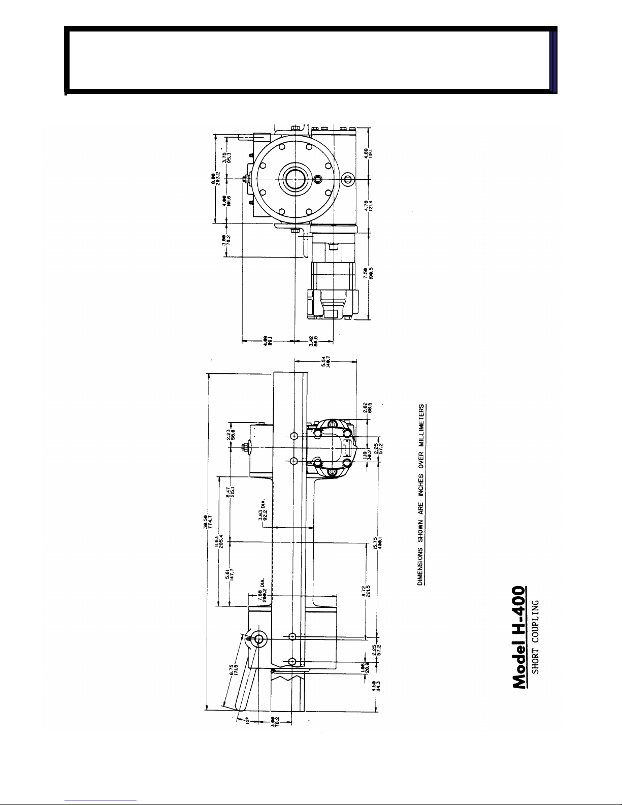
MODEL H-400 SHORT COUPLING
DIMENSIONAL DRAWING
21
Page 22

56
3
MODEL 400 EXPLODED VIEW
22
Page 23

ITEM NO. QTY PART NO. DESCRIPTION ITEM NO. QTY PART NO. DESCRIPTION
1 2 302124 ANGLE 400 29 1 400003 BALL POPPET
2 2 302125 ANGLE Y 400 30 2 402044 BEARING BALL
3 1 308046 BUSHING 31 1 412005 BUSHING
4 2 308048 BUSHING 32 NO LONGER USED
5 1 316003 CAP 33 12 414139 CAPSCREW 5/16- 18 NC X 1-1/4
6 1 316004 CAP 34 8 414140 CAPSCREW 5/16- 18NC X 3/4
7 1 324163 CLUTCH JAW 35 4 414457 CAPSCREW 7/16-14NC X 1 1/4
8 1 328010 COVER 36 4 414481 CAPSCREW 7/16 - 14NC X 1 1/4
9 2 33
0010 SHOE DRAG BRAKE 37 1 414971 SCREW POPPET
10 1 332074 DRUM Y400 38 1 416059 SET SCREW 3/8 - 16 NC X 1/2
11 1 332139 DRUM 400 39 1 416109 SETSCREW 5/16 - 18NC X 1/2
12 1 334009 GEARY LH 40 1 416112 SET SCREW 5/16 - 18NC X 3/4
13 1 334016 GEAR RH 41 12 418163 LOCKWASHER 5/16
14 1 338009 HOUSING CLUTCH 42 8 418198 LOCKWASHER 7/16
15 1 338010 HOUSING GEAR 43 8 442182 GASKET
16 1 342024 KEY SQ END 44 1 442183 GASKET
17 1 NO LONGER USED 45 3 456006 FITTING LUBE
18 1 34
2051 KEY RD END 46 1 456008 FITTING RELIEF
19 2 342120 KEY RD END 47 2 462003 QUAD RING
20 2 450017 KEY BARTH 48 1 468002 REDUCER
21 1 356702 SHAFT DRUM 400 49 1 468010 PLUG PIPE
22 1 356716 SHAFT DRUM Y400 50 1 468011 PLUG PIPE
23 1 356902 SHAFT SHIFTER 51 1 486011 SEAL OIL
24 1 358001 SHIFTER HANDLE 52 1 486067 SPRING
25 1 362007 SPACER DRUM 53 2 494088 SPRING
26 1 368004 WORM RH 54 2 494089 SPRING
27 1 368006 WORM LH 55 2 530094 SPACER-BRAKE DISC
28 1 370057 YOKE 56 1 402400 BU
SHING-DU
PARTS LIST FOR MODEL 400
23
Page 24

58
5
MODEL H-400 EXPLODED VIEW
24
Page 25

ITEM NO. QTY PART NO. DESCRIPTION ITEM NO. QTY PART NO. DESCRIPTION
1 1 299043 COUPLING ASSY 30 1 412005 BUSHING
2 1 300043 ADAPTER 31 NO LONGER USED
3 2 302459 ANGLE H400 32 6 414139 CAPSCREW 5/16- 18 NC X 1-1/4
4 2 302669 ANGLE HY400 33 8 414140 CAPSCREW 5/16- 18NC X 3/4
5 1 309046 BUSHING 34 4 414457 CAPSCREW 7/16-14NC X 1 1/4
6 2 309048 BUSHING 35 4 414481 CAPSCREW 7/16 - 14NC X 1 1/4
7 1 316004 CAP 36 6 414871 CAPSCREW 5/16 18NC X 1 1/4
8 1 324163 CLUTCH J
AW 37 2 414950 CAPSCREW 1/2 - 13NC X 1 3/4
9 1 328010 COVER 38 1 414971 SCREW POPPET
10 2 330010 SHOE DRAG BRAKE 39 1 416059 SETSCREW 3/8 16 NC X 1/2
11 1 332074 DRUM 6400 40 1 416109 SETSCREW 5/16 - 18NC X 1/2
12 1 332138 DRUM 400 41 1 416112 SET SCREW 5/16 - 18NC X 3/4
13 1 334016 GEAR RH 42 6 418163 LOCKWASHER 5/16
14 1 338009 HOUSING CLUTCH 43 8 418198 LOCKWASHER 7/16
15 1 338010 HOUSING GEAR 44 2 442182 GASKET
16 1 342024 KEY SQ END 45 1 442183 GASKET
17 1 NO LO
NGER USED 46 3 456006 FITTING LUBE
18 2 342051 KEY RD END 47 1 456008 FITTING RELIEF
19 2 342120 KEY RD END 48 1 458025 MOTOR - HYD
20 1 450017 SKEY BARTH 49 2 462003 QUAD RING
21 1 356702 SHAFT DRUM 400 50 1 468002 REDUCER
22 1 356716 SHAFT DRUM Y400 51 1 468010 PLUG PIPE
23 1 356902 SHAFT SHIFTER 52 1 468011 PLUG PIPE
24 1 358001 SHIFTER HANDLE 53 1 486067 SEAL OIL
25 1 362007 SPACER DRUM 54 1 494005 SPRING
26 1 368004 WORM RH 55 2 494088 SPRING
27 1 370057 YOKE 56 2 494089 SPR
ING
28 1 400003 BALL POPPET 57 2 530094 SPACER-BRAKE DISC
29 2 402044 BEARING BALL 58 1 402400 BUSHING-DU
PARTS LIST FOR MODEL H-400
25
Page 26

57
3
MODEL H-400 SHORT COUPLING
EXPLODED VIEW
26
Page 27

ITEM NO. QTY. PART NO. DESCRIPTION ITEM NO. QTY. PART NO. DESCRIPTION
1 1 300062 ADAPTER 30 4 414457 CAPSCREW 7/16-14NC X 1 1/4
2 1 302956 ANGLE 31 4 414481 CAPSCREW 7/16 - 14NC X 1 1/4
3 1 308046 BUSHING 32 6 414887 CAPSCREW 5/16 - 18NC X 1
4 2 308048 BUSHING 33 2 414952 CAPSCREW 1/2 X 13 NC X 1-1/2
5 1 316004 CAP BEARING 34 1 414971 SCREW POPPET
6 1 324163 CLUTCH JAW 35 1 416059 SET SCREW 3/8 - 16 NC X 1/2
7 1 328010 COVER 36 1 416109 SETSCREW 5/16 - 18NC
X 1/2
8 2 330010 SHOE DRAG BRAKE 37 1 416112 SET SCREW 5/16 - 18NC X 3/4
9 1 332139 DRUM 38 6 418163 LOCKWASHER 5/16
10 1 334016 GEAR RH 39 8 418198 LOCKWASHER 7/16
11 1 338009 HOUSING CLUTCH 40 2 418218 LOCKWASHER 1/2
12 1 338269 HOUSING GEAR 41 2 442182 GASKET
13 1 342024 KEY SQ END 42 1 442183 GASKET
14 NO LONGER USED 43 3 456006 FITTING LUBE
15 2 342120 KEY RD END 44 1 456008 FITTING RELIEF
16 2 450017 KEY BARTH 45 1 458025 MOTOR
17 1 356702 SHAFT DRUM 46 2 462003 QUAD
RING
18 1 356902 SHAFT SHIFTER 47 1 468002 REDUCER
19 1 358052 SHIFTER HANDLE 48 1 468010 PLUG PIPE
20 1 362007 SPACER DRUM 49 1 468011 PLUG PIPE
21 1 368183 WORM RH 50 1 486079 SEAL PILOT
22 1 370057 YOKE 462029 O-RING
23 1 400003 BALL POPPET 51 1 494005 SPRING
24 1 402044 BEARING BALL 52 2 494088 SPRING
25 1 402107 BEARING THRUST 53 2 494089 SPRING
26 1 412005 BUSHING 54 2 518026 WASHER THRUST
27 NO LONGER USED 55 2 530094 SPACER-BRAKE DISC
28 6 414139 CAPSCREW 5/16 - 17 N
C X 1-1/4 56 1 302955 ANGLE
29 8 414140 CAPSCREW 5/16 18NC X 3/4 57 1 402400 BUSHING - DU
MODEL H-400 SHORT COUPLING
PARTS LIST
27
Page 28

ITEM NO. QTY.
ARTS NO
.
DESCRIPTION
101 1 306036 SPRING FLAT
102 1 314003 CAM PLATE
103 1 328057 COVER
104 1 338038 HOUSING BRAKE
105 1 340024 HUB
106 1 342051 KEY
107 1 352020 RETAINER PLATE
108 1 368057 WORM RH
109 1 368080 WORM RH
110 2 400007 BALL
111 4 414111 CAPSCREW 5/16 18 NC X 1
112 2 414398 CAPSCREW 3/8 - 24NF X 1 3/4
113 1 414603 CAPSCREW 1/2 - 20UNF X 1 3/4
114 6 414865 CAPSCREW 5/16 18 NC X 1
115 1 418067 NUT JAM
116 4 418163 LOCKWASHER 5/16
117 2 418184 WASHER FLAT 3/8
118 1 4
42182 GASKET
119 1 442190 GASKET
120 1 474004 THRUST PLATE
121 1 486076 THREAD SEAL
122 1 494010 SPRING
MODEL 400/H-400 BRAKE DRAWING AND
PARTS LIST
28
Page 29

Page 30

LIMITED WARRANTY
RAMSEY WINCH warrants each new RAMSEY Winch to be free from defects in material and workmanship for a period of one (1) year from date of purchase.
The obligation under this warranty, statutory or otherwise, is limited to the replacement or repair at the
Manufacturer's factory, or at a point designated by the Manufacturer, of such part that shall appear to the
Manufacturer, upon inspection of such part, to have been defective in material or workmanship.
This warranty does not obligate RAMSEY WINCH to bear the cost of labor or transportation charges in connection
with the replacement or repair of defective parts, nor shall it apply to a product upon which repair or alterations have
been made, unless authorized by Manufacturer, or for equipment misused, neglected or which has not been installed
correctly.
RAMSEY WINCH shall in no event be liable for special or consequential damages. RAMSEY WINCH makes no warranty in respect to accessories such as being subject to the warranties of their respective manufacturers.
RAMSEY WINCH, whose policy is one of continuous improvement, reserves the right to improve
its products through
changes in design or materials as it may deem desirable without being obligated to incorporate such changes in
products of prior manufacture.
If field service at the request of the Buyer is rendered and the fault is found not to be with RAMSEY WINCH's product,
the Buyer shall pay the time and expense to the field representative. Bills for service, labor or other expenses that
have been incurred by the Buyer without approval or authorization by RAMSEY WINCH will not be accepted
See warranty card for details.
RAMSEY WINCH COMPANY
Post Office Box 581510 Tulsa, Oklahoma 74158-1510
Telephone: (918) 438-2760 FAX: (918) 438-6688
Visit us on the web: www.ramsey.com
OM-914143-1206-D
Ramsey Winch Company
Post Oce Box 581510
Tulsa, Oklahoma 74158-1510
Telephone: (#918) 438-2760 FAX: (#918)
438-6688
 Loading...