

Page 1

OPERATING, SERVICE AND
MAINTENANCE MANUAL
MODEL RPH 53,3 PLANETARY WINCH
CAUTION: READ AND UNDERSTAND THIS MANUAL BEFORE INSTALLATION AND
OPERATION OF WINCH. SEE WARNINGS!
English . . . . . . . . . . . . . . . . . . . . .1
Français . . . . . . . . . . . . . . . . . . .18
Deutsch . . . . . . . . . . . . . . . . . . .34
Español . . . . . . . . . . . . . . . . . . .50
Ramsey Winch Company
P.O. Box 581510 - Tulsa, OK 74158-1510 USA
Phone: (918) 438-2760 - Fax (918) 438-6688
Visit us at http://www.ramsey.com
OM-914215-1012-B
INTENDED USE: VEHICLE RECOVERY AND PULLING OF LOADS
Page 2

Page 3

TABLE OF CONTENTS
I
NTRODUCTIONS . . . . . . . . . . . . . . . . . . . . . . . . . . . . . . . . . . . . . . . . . . . . . . . . . . . . . . . . . . . . . . . . . . . . . . .3
SPECIFICATIONS . . . . . . . . . . . . . . . . . . . . . . . . . . . . . . . . . . . . . . . . . . . . . . . . . . . . . . . . . . . . . . . . . . . . . . .3
WARNINGS . . . . . . . . . . . . . . . . . . . . . . . . . . . . . . . . . . . . . . . . . . . . . . . . . . . . . . . . . . . . . . . . . . . . . . . . . . .3
USER’S RESPONSIBILITY FOR CE COMPLIANCE . . . . . . . . . . . . . . . . . . . . . . . . . . . . . . . . . . . . . . . . . . . . . . .3
WINCH MOUNTING . . . . . . . . . . . . . . . . . . . . . . . . . . . . . . . . . . . . . . . . . . . . . . . . . . . . . . . . . . . . . . . . . . . . .4
ROPE INSTALLATION . . . . . . . . . . . . . . . . . . . . . . . . . . . . . . . . . . . . . . . . . . . . . . . . . . . . . . . . . . . . . . . . . . . .4
MAINTENANCE . . . . . . . . . . . . . . . . . . . . . . . . . . . . . . . . . . . . . . . . . . . . . . . . . . . . . . . . . . . . . . . . . . . . . . . .5
OPERATION . . . . . . . . . . . . . . . . . . . . . . . . . . . . . . . . . . . . . . . . . . . . . . . . . . . . . . . . . . . . . . . . . . . . . . . . . . .5
HYDRAULIC SYSTEM REQUIREMENTS . . . . . . . . . . . . . . . . . . . . . . . . . . . . . . . . . . . . . . . . . . . . . . . . . . . . . .6
PERFORMANCE CHARTS . . . . . . . . . . . . . . . . . . . . . . . . . . . . . . . . . . . . . . . . . . . . . . . . . . . . . . . . . . . . . . . . .6
TROUBLE SHOOTING GUIDE . . . . . . . . . . . . . . . . . . . . . . . . . . . . . . . . . . . . . . . . . . . . . . . . . . . . . . . . . . . . . .7
END OF SERVICE MEASURES . . . . . . . . . . . . . . . . . . . . . . . . . . . . . . . . . . . . . . . . . . . . . . . . . . . . . . . . . . . . .8
OVERHAUL INSTRUCTIONS . . . . . . . . . . . . . . . . . . . . . . . . . . . . . . . . . . . . . . . . . . . . . . . . . . . . . . . . . . . .8-10
DIMENSIONAL DRAWINGS . . . . . . . . . . . . . . . . . . . . . . . . . . . . . . . . . . . . . . . . . . . . . . . . . . . . . . . . . . . .11-12
PARTS LIST AND PARTS DRAWINGS . . . . . . . . . . . . . . . . . . . . . . . . . . . . . . . . . . . . . . . . . . . . . . . . . . . .13-16
CE DECLARATION OF CONFORMITY . . . . . . . . . . . . . . . . . . . . . . . . . . . . . . . . . . . . . . . . . . . . . . . . . . . . . . .17
Page 4
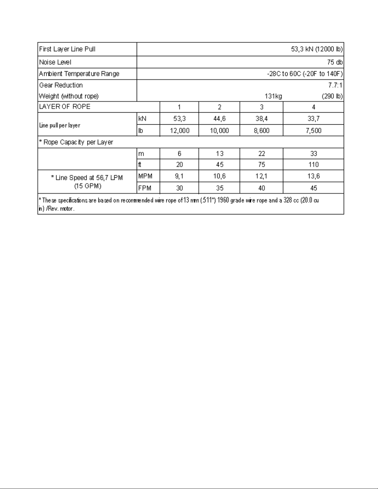
SPECIFICATIONS*
WARNINGS:
THE USER SHALL ENSURE THAT THE OPERATING PERSONNEL ARE GIVEN THE NECESSARY TRAINING.
THE OPERATOR SHALL ALWAYS WORK IN COMPLIANCE WITH THE OPERATING INSTRUCTIONS.
A MOTOR SPOOL (OPEN CENTER) DIRECTIONAL CONTROL VALVE IS REQUIRED FOR BRAKE OPERATION.
CLUTCH MUST BE FULLY ENGAGED BEFORE STARTING THE WINCH.
DO NOT DISENGAGE CLUTCH UNDER LOAD.
STAY OUT FROM UNDER AND AWAY FROM RAISED LOADS.
STAND CLEAR OF ROPE WHILE PULLING. DO NOT TRY TO GUIDE ROPE.
DO NOT USE WINCH TO LIFT, SUPPORT, OR OTHERWISE TRANSPORT PERSONNEL.
A MINIMUM OF 2 WRAPS OF ROPE AROUND THE DRUM BARREL IS NECESSARY TO HOLD THE LOAD.
IN CAR CARRIER APPLICATIONS, AFTER PULLING VEHICLE ON CARRIER, BE SURE TO SECURE VEHICLE TO CARRIER
BED. DO NOT MAINTAIN LOAD ON WINCH ROPE WHILE TRANSPORTING VEHICLE. DO NOT USE WINCH AS A TIEDOWN.
AVOID CONDITIONS WHERE LOAD SHIFTS OR JERKS OCCUR. EXCESSIVE “INCHING” SHALL BE AVOIDED.
USER’S RESPONSIBILITY FOR CE COMPLIANCE
1. Use only a motor spool (open center) control valve Per Hydraulic System Requirements.
2. If a remote-operated winch control valve is used, refer to Hydraulic System Requirements for
Emergency Stop components to be installed.
3. Adjust system relief pressure per Hydraulic System Requirements
4. Mount winch per Winch Mounting Instructions.
5. Install 13 mm (.511 inch), grade 1960 wire rope. Maximum rope length of 33 M (110 ft) for
four layers maximum. Attach rope to the drum per Rope Installation Instructions. Hook must
have a safety latch and a minimum breaking strength of 133 kN.
4
Page 5

WINCH MOUNTING
ESSENTIAL MOUNTING INSTRUCTIONS TO MAINTAIN ALIGNMENT OF PLANETARY WINCH COMPONENTS:
I
t is most important that this winch be mounted
securely so that the three major sections (the motor
end, the rope drum, and the gear housing end) are
properly aligned. Excessive bushing wear and difficulty
in freespooling are usually symptoms of misalignment.
In the as-installed condition, if the winch is
mid-mounted, then at least one tie-plate must be
attached to the mounting feet at the bottom of the
winch to maintain alignment. If the winch is foot
mounted then at least one tie-plate must remain
mounted at midpoint of winch to maintain alignment. It
is always preferred to used BOTH tie-plates in the final
installed configuration.
When mounting the winch, the mounting hole patterns
described in the Dimensional drawings on pages
11-12 should be used. The mounting surface must be
flat within 0,38 mm (.015 in) and sufficiently stiff to
resist flexing. If a steel plate is used for foot mounting,
it should be 19 mm (.75 in) thick. For this mounting
application eight (8) 1/2-13NC x 1-1/2” long grade 5
capscrews with lockwashers will be needed to mount winch. Capscrews should be tightened to 235 Nm (173 ft-lb) torque.
NOTE: If angles or a steel plate are used in mounting winch, tie-plates provided with winch are to be attached to the remaining mounting
pads, whether they be side or foot.
ROPE INSTALLATION
1. Unwind rope by rolling it out along the ground
to prevent kinking. Securely wrap end of
rope, opposite hook, with plastic or similar
tape to prevent fraying.
2. Slide the wire rope through narrow end of the
pocket against the drum flange. Wrap the
wire rope around on the anchor “puck” (item
#20) and pull the wire rope and anchor back
into the wide end of the pocket. Use a soft
hammer to drive the back side of the wire
rope, firmly seating the wire rope and anchor
into the pocket.
3. Carefully run winch in the "reel-in" direction.
Keeping tension on end of rope, spool all the
rope onto the rope drum, taking care to form
neatly wrapped layers.
After installing rope, check freespool
operation. Disengage clutch and pull on rope
at a walking speed. If rope “birdnests”,
loosen jam nut (item #22) and turn nylon
setscrew (item #17) clockwise to increase
drag on drum. If rope pull is excessive,
loosen nylon setscrew by turning
counterclockwise. Tighten jam nut when
proper setting is obtained.
CAUTION: OVER-TIGHTENING OF JAM NUT
MAY STRIP NYLON SETSCREW.
5
Page 6

MAINTENANCE
1. Inspect the rope for damage and lubricate frequently. If the rope becomes frayed with broken strands, replace immediately.
2. Check that the clutch is fully engaging. See OPERATION instructions, above, for the appropriate clutch shifter. FOR MANUAL CLUTCH
ONLY: Monthly, disengage clutch, put several drops of oil on the clutch handle shaft and work clutch handle IN and OUT several times
to lubricate inside the shifter assembly.
3. Check to see that the drum rope does not overrun (“birdnest”) when freespooling. Refer to page 4 if it does.
4. Replace drum bushings and seals if seals begin to seep grease. Refer to the Overhaul Instructions, pages 8-10. Add additional
lubricant, Mobilith SHC 007, to gears and drum bearings if required.
OPERATION
The best way to get acquainted with how your winch operates is to make test runs before you actually use it. Plan your test in advance.
Remember, you hear your winch as well as see it operate. Get to recognize the sounds of a light steady pull, a heavy pull, and sounds
caused by load jerking or shifting. Avoid conditions where load shifts or jerks occur, as they may indicate a dangerous situation.
The uneven spooling of rope, while pulling the load, is not a problem, unless there is a rope pileup on one end of the drum. If this happens,
reverse the winch to relieve the load, and move your anchor point further to the center of the vehicle. After the job is done you can unspool
and rewind for a neat lay of the rope.
When pulling a heavy load, place a blanket, jacket, and tarpaulin over the rope about five or six feet behind the hook. In the event of a broken
rope, this will slow the snap back of the rope and could prevent serious injury.
The winch clutch allows rapid unspooling of the rope, from the rope drum, for hooking onto the load. The clutch is operated by the clutch
shifter lever or air shifter.
WARNING: DO NOT DISENGAGE CLUTCH UNDER LOAD!
MANUAL CLUTCH SHIFTER (Refer to dimensional drawing page 11):
TO DISENGAGE CLUTCH: Run the winch in the reverse (reel out) direction until the load is off the rope. Pull handle out and rotate 90°. With
handle in the “DISENGAGED” position, rope may now be free-spooled from the drum.
TO ENGAGE CLUTCH: Pull handle out, rotate 90° and release handle. Run the winch in reverse until the clutch handle snaps fully into the
“ENGAGED” position. DO NOT attempt to pull a load unless the handle is fully at the “ENGAGED” position. If manual shift indicator light is
present, the green light is lit when clutch is fully “ENGAGED”. DO NOT attempt to pull a load unless the green light is lit. To install light to the
vehicle electrical system refer to the Electrical Schematic on page 12.
AIR CYLINDER CLUTCH SHIFTER (Refer to the dimensional drawing page 12):
TO DISENGAGE CLUTCH: Run the winch in the reverse (reel out) direction until load is off the rope. Apply air pressure to the .125-27 NPT
port: 5,5 bar (80 PSI) (min.)- 10,3 bar (150 PSI) (max.). CAUTION: PRESSURE MUST NOT EXCEED 10,3 bar (150 PSI).
TO ENGAGE CLUTCH: Remove air pressure from the cylinder (a return spring engages the plunger). Run winch in reverse until the clutch
engagement indicator light (green light) is lit. To install light to the vehicle electrical system refer to the Electrical Schematic on page 12.
6
Page 7

Refer to the performance charts below to properly match your hydraulic system to the winch performance. The
charts consist of: (1) Line Pull first layer kN (lb) vs. Working Pressure bar (PSI). (2) Line Speed, first layer MPM
(FPM) vs. flow LPM (GPM).
HYDRAULIC SYSTEM REQUIREMENTS
1. Motor spool (open center) control valve
2. Emergency Stop:
A. If winch is controlled by a direct-operated manual valve, that valve serves as the E-stop.
B. If a remote operated control valve is used, a solenoid-operated hydraulic dump valve, normally open to
tank, and an emergency stop switch (to open the dump valve) is required. The E-stop switch is to be
normally closed and have a red, resettable push button actuator with a yellow background. The E-stop
switch must be easily accessible to the operator.
3. Relief valve set to 172,4 bar (2500 psi) which is the rated capacity limiter.
4. Flow rate of 56,7 LPM (15 GPM) maximum. Do not exceed 75,7 LPM (20 GPM) or motor and winch may
be damaged.
5. Hydraulic fluid with a viscosity between 20-43 cSt (100-200 SUS). Maximum operating temperature
85C (180F). Cleanliness level of ISO 17-14 or better.
7
Page 8

TROUBLESHOOTING GUIDE
8
CONDITIONS POSSIBLE CAUSE CORRECTION/ACTION
DRUM WILL NOT ROTATE
AT NO LOAD
Winch not mounted squarely, causing end bearing
to bind up
Check mounting. Refer to Winch Mounting, page 4.
Gears damaged Inspect and replace damaged gears
DRUM WILL NOT ROTATE
UNDER LOAD
Winch not mounted squarely, causing end bearing
to bind up
Check mounting. Refer to Winch Mounting, page 4.
Load greater than rated capacity of winch Refer to Specifications page 3 for line pull rating.
Low hydraulic system pressure Check pressure. Refer to Hydraulic Systems
performance charts page 6.
WINCH RUNS TOO SLOW Low hydraulic system flow rate Check flow rate. Refer to Systerm Requirements and
Typical Layout page 6.
Motor worn out Replace motor
DRUM WILL NOT
FREESPOOL
Clutch not disengaged. Check Adjustment of Manual
Shifter, page 9.
Check Operation, page 5.
Winch not mounted squarely, causing end bearing
to bind up
Check mounting. Refer to Winch Mounting, page 4.
Side mounted bolts too long, causing binding of ring
gear (Item #18, page 13).
Check bolt length. Bolt thread MUST NOT engage
threaded holes in sides of end bearing more than
between 12,7 mm (.50 in) and 17,5 mm (.68 in)
thread depth in the end bearing.
BRAKE WILL NOT HOLD Incorrect directional control valve (cylinder
spool-closed center)
Use only a motor spool (open center) control valve.
LOAD DRIFTS Excessive Backpressure 6,9 bar (100 PSI) Max. Check for restrictions in hydraulic system. Refer to
System Requirements and Typical Layout page 6.
ROPE BIRDNESTS WHEN
CLUTCH IS DISENGAGED
Drag screw improperly adjusted Adjust nylon drag screw. Refer to Rope Installation,
page 4.
EXCESSIVE NOISE Hydraulic system flow too high Check flow rate. Refer to Typical Layout page 6.
Drum in bind, winch not mounted squarely Check mounting. Refer to Winch Mounting, page 4.
DRUM CHATTERS IN
“REEL IN” DIRECTION
Low hydraulic system flow rate Check flow rate. Refer to Typical Layout page 6.
Low hydraulic system relief pressure setting Check relief valve setting.
OIL LEAKS FROM
BREATHER VENT UNDER
MOTOR END BEARING
Damaged brake o-rings, backup rings, or sealing
surfaces
Disassemble brake and inspect. See Overhaul
Instructions, pg. 8.
Page 9

END OF SERVICE MEASURES
When winch reaches the end of it’s servicable life, dispose of per local environmental regulations.
INSTRUCTIONS FOR OVERHAUL RPH 53,3 SERIES WINCH
Take note of mounting configurations for proper mounting of parts during re-assembly. Replace all gaskets, o-rings,
and seals during re-assembly.
Disconnect tube (item #44) from elbows (item #24) on
bottom of brake (item #6) and valve (item #45). Remove
motor (item #31) from brake housing (item #6) by
unscrewing capscrews (item #15). Tap motor lightly to
disengage. Replace all gaskets, o-rings and seals with new
ones during re-assembly.
Remove coupling (item #23) from brake housing. Examine
coupling for signs of wear, replace if necessary. If necessary,
remove valve (item #45) from motor by removing capscrews
(item #18) and lockwashers (item #49). If valve is removed
make sure two square cross section o-rings remain seated in
their counter bores in valve.
Remove brake housing (item #6) from end bearing (item #4)
by unscrewing (6) capscrews (item #14) in a criss-cross
pattern (2 turns each) until all capscrews are removed from
brake housing. Remove brake parts from brake housing.
Examine brake discs (item #26) for signs of wear, and
replace if necessary. Examine o-rings (items #34 & #35)
and backup rings (items #36 & #37) for signs of wear.
Remove o-rings and backup rings from grooves in brake
piston (item #3).
Remove and examine springs (items #42 & #43) for
damage, replace if necessary.
Examine fitting (item #30) to assure that fittings are in proper
working condition, replace if necessary.
Remove tie plates (item #9) from end bearings (items #4 &
#5) by unscrewing capscrews (item #16), as shown.
Remove snap ring (item #41) and thrust washer (item #48)
from shaft. Slide motor end bearing (item #4) from drum
(item #1) and drum from gear housing end bearing (item
#5).
Remove input shaft (item #8) and thrust washer (item #47)
from end bearing. Inspect gear teeth and splined end of shaft
for signs of wear. If damaged, it will be necessary to replace
shaft.
9
Page 10

Remove o-ring (item #32), bushing (item #12) from outside of
motor end bearing (item #4), remove o-ring (item #33), bearing
(item #11) from inside of motor end bearing (item #4). Place
new, well oiled, o-ring (item #33) into groove inside of end
bearing and press new bearing (item #11) into end bearing.
Press bushing (item #12) onto end bearing and dip o-ring
(item #32) in oil and seat into groove of end bearing.
Remove seal (item #40) from gear housing end bearing (item
#5). Loosen nut (item #21) and remove nylon setscrew (item
#18) and remove ring gear (item #29) from gear housing end
bearing, if necessary. Remove bushing (item #13) and bearing
(item #10) from gear housing end bearing (item #5). Press new
bushing (item #13) and bearing (item #10) into place in end
bearing. Install ring gear and nylon setscrew and nut. Ring gear
must be fully seated in gear housing end bearing (item #5) and
slot in ring gear must NOT be aligned with clutch shifter hole.
Install new seal in gear housing end bearing, with sharp edge of
seal outward.
Generously apply grease (MOBILITH SHC 007) to teeth of ring gear (item #29), teeth of planet gears in drum (item #1) and to bushing in
gear housing end bearing (item #5). Apply a small amount of grease to base of bushing on motor end bearing (item #4). Apply grease to
teeth of gear and short end of shaft (item #8). Place gear end of shaft through thrust washer (item #47) and into bearing in end bearing
(item #5). Place drum over shaft and rotate drum to engage planet gears with output gear on shaft and with ring gear in end bearing.
Assemble end bearing (item #4) to drum assembly and use tie plates (item #9) and capscrews (item #16) to hold both end bearings
together. Tighten capscrews to 75 Nm (55 ft-lb). Slide thrust washer (item #48) over end of shaft and against end bearing (item #4). Place
snap ring (item #41) into groove in splined end of shaft.
If necessary, remove and replace appropriate shifter assembly (item #2 or #3), as follows:
MANUAL CLUTCH SHIFTER ASSEMBLY
Loosen setscrew (item #19) and jam nut, then unscrew manual shifter assembly (item #2). Be sure slot in ring gear is not aligned with
clutch shifter hole. Rotate drum, if necessary, to ensure hole and slot are not aligned.
Reinstall shifter assembly with plunger, jam nut, and handle positioned in gear housing as shown below. Thread assembly (with handle
engaged in cylinder slot) into the gear housing. Pull drum toward the gear end bearing housing to remove play. Hold drum in position and
continue threading the shifter assembly in until the gap between the end of the handle and cylinder is
11,1
+0
- 1,6
mm(7/16
+0
-1/16
in) and handle is in the horizontal position (see below). Note: This gap will vary with drum endplay. With
the drum pulled against the motor end housing, the gap should be 10 mm (.38 in).
Lightly tighten jam nut. Rotate drum until handle snaps fully into the engaged position. Pull handle out and rotate 90°. Verify that drum can be
rotated freely (at least one full revolution) with
clutch shifter at the DISENGAGED position.
Securely tighten jam nut while holding the handle.
Tighten setscrew (item #19) securely. Re-check
clutch operation as described on page 5.
AIR CYLINDER SHIFTER ASSEMBLY
Loosen set screw (item #19) to remove shifter
assembly (item #3). To reinstall, place 1 or 2
shims (items #44) over plunger and thread shifter
assembly into gear end housing. Add or remove
shims to orient ports for pneumatic connections.
Ports should point
down (below horizontal).
Tighten setscrew. Check for clutch operation as
described on page 5.
If the light assembly (item #2) or light switch
(item #48) needs to be replaced, refer to the
schematic on page 12 for electri
cal connections
and disassemble and reassemble as shown.
10
Page 11

Set winch on gear housing end with motor end bearing (item #4) up. Insert (6) springs (item #42) into pockets of motor end
bearing (item #4), as shown, leaving top and bottom pockets empty. Install coupling (item #23) over splined end of shaft (item
#8). Put (4) brake pins (item #7) into (4) holes in motor end bearing. Install well-oiled o-ring (items #34 & #35) and backup
rings (items #36 & #37) into grooves in O.D. of piston (item #3). Place o-rings into portions of grooves nearest to center of
piston in both cases. See SECTION A-A below.
Piston (item #3), brake disc (item #26) and separator plates
(item #39) must be clean and free of grease and oil. Place
piston over pins (item #7) and on top of springs (item #42).
Place separator plates (item #39) and brake disc alternately
on top of piston, as shown below. Press larger diameter end of
(4) springs (item #43) into pockets in brake housing (item
#6). Place gasket (item #27) on top of end bearing (item
#4). Place brake housing over brake parts with fitting ports
downward toward mounting feet. Align mounting holes and
force brake housing down onto end bearing (item #4). Apply
271 Loc-tite to 6 capscrews (item #14) and finger tighten
until flush with surface of brake housing. Torque capscrews
(2 turns each) in a criss-cross pattern until a torque of 41 Nm
(30 ft-lb) per capscrew, is achieved.
Place gasket (item #28) into position on mounting surface of motor (item #31). Slide motor shaft into coupling and attach
motor to brake housing (item #6). Use (2) capscrews (item #15) with lockwashers (item #22) and torque to 118 Nm
(87 ft-lb) each. Securely connect tube (item #44) to elbows (item #24) in valve (item #45) and in bottom of brake housing
(item #6).
Apply at least 37,9 bar (550 PSI) hydraulic system pressure to release brake and verify that brake releases, by observing that
the winch drum rotates.
11
Page 12

12
RPH 53,3 MANUAL SHIFTER
Page 13

13
RPH 53,3 AIR SHIFTER
Page 14

14
RPH 53,3 MANUAL SHIFTER
Page 15

15
PARTS LIST RPH 53,3 WITH MANUAL CLUTCH SHIFTER
ITEM QTY. PART NO. DESCRIPTION
1 1 234226 DRUM ASS'Y.
2 1 276052 SHIFTER ASS'Y. - MANUAL
3 1 296611 END BEARING - MOTOR
4 1 306042 PISTON - BRAKE
5 1 334177 GEAR-RING
6 1 338297 HOUSING - GEAR, END BEARING
7 1 338302 HOUSING - BRAKE
8 NOT USED
9 4 346045 PIN - BRAKE
10 1 357518 SHAFT - INPUT
11 2 395236 TIE PLATE
12 1 402120 BEARING
13 1 402121 BEARING - MOTOR END BEARING
14 1 412095 BUSHING - DRUM (MTR. END)
15 1 412096 BUSHING - DRUM (G.HSG. END)
16 4 414159 CAPSCREW - 5/16-18 X 1-1/2 LG HX HD GR5 Z/P
17 6 414303 CAPSCREW - 3/8-16NC X 2-1/2 LG. HX HD GR5 PLTD
18 8 414664 CAPSCREW - 5/8-11NC X 1 LG. HX. HD., GR. 5
19 1 414926 SETSCREW - 3/8-16NC X 1 LG., SOCKET, NYLON
20 2 414948 CAPSCREW - 1/2-13NC X 1-1/4 LG., HX. SOC. HD.
21 1 315009 ROPE ANCHOR
22 1 418036 NUT 3/8 - 16NC HEX. JAM
23 4 418063 LOCKWASHER - 5/16 MED SECT Z/P
24 2 418218 LOCKWASHER - 1/2 ID MED. SECT.
25 1 431015 COUPLING - BRAKE
26 2 432018 FITTING - 7/16 ELBOW
27 4 438022 DISC - BRAKE
28 1 442220 GASKET - BRAKE
29 1 442223 GASKET - MOTOR
30 1 456038 FITTING - VENT
31 1 458171 MOTOR-HYDRAULIC
32 1 462056 O-RING
33 1 462057 O-RING
34 1 462058 O-RING
35 1 462059 O-RING
36 1 462060 O-RING
37 1 462061 O-RING (DRUM)
38 1 472052 PLUG
39 5 474111 PLATE SEPARATOR
40 1 486081 SEAL-GEAR HSG.
41 1 490037 SNAP RING
42 6 494110 SPRING - BRAKE
43 4 494112 SPRING
44 1 509143 TUBE ASSEMBLY
45 1 516055 VALVE - MOTOR CONTROL
46 1 518037 THRUST WASHER
47 1 518047 THRUST WASHER
48 1 518052 THRUST WASHER
49 1 518053 THRUST WASHER (MTR. END)
50 1 518054 THRUST WASHER (G. HSG. END)
51 1 434573 NAME AND DATA PLATE
Page 16

16
RPH 53,3 AIR SHIFTER
Page 17

17
PARTS LIST RPH 53,3 WITH AIR-CYLINDER CLUTCH SHIFTER
ITEM QTY. PART NO. DESCRIPTION
1 1 234226 DRUM ASS'Y.
2 1 236020 LIGHT ASS'Y
3 1 276053 SHIFTER ASS'Y. - AIR
4 1 296611 END BEARING - MOTOR
5 1 306042 PISTON - BRAKE
6 1 312526 BRACKET - LIGHT MTG.
7 1 334177 GEAR-RING
8 1 338297 HOUSING -GEAR, END BEARING
9 1 338302 HOUSING - BRAKE
10 4 346045 PIN - BRAKE
11 1 357518 SHAFT - INPUT
12 2 395236 TIE PLATE
13 1 402120 BEARING
14 1 402121 BEARING - MOTOR END BEARING
15 1 412095 BUSHING - DRUM (MTR. END)
16 1 412096 BUSHING - DRUM (G.HSG. END)
17 2 414036 CAPSCREW - 1/4-20NC X 1/2 HX HD GR5 F/B
18 4 414159 CAPSCREW - 5/16-18 X 1-1/2 LG HX HD GR5 Z/P
19 6 414303 CAPSCREW - 3/8-16NC X 2-1/2 LG. HX HD GR5 PLTD
20 8 414664 CAPSCREW - 5/8-11NC X 1 LG. HX. HD., GR. 5
21 1 414926 SETSCREW - 3/8-16NC X 1 LG., SOCKET, NYLON
22 2 414948 CAPSCREW - 1/2-13NC X 1-1/4 LG., HX. SOC. HD.
23 1 315009 ROPE ANCHOR
24 1 418036 NUT 3/8 - 16NC HEX. JAM
25 4 418063 LOCKWASHER - 5/16 MED SECT Z/P
26 2 418218 LOCKWASHER - 1/2 ID MED. SECT.
27 1 431015 COUPLING - BRAKE
28 2 432018 FITTING - 7/16 ELBOW
29 4 438022 DISC - BRAKE
30 1 442220 GASKET - BRAKE
31 1 442223 GASKET - MOTOR
32 1 456038 FITTING - VENT
33 1 458171 MOTOR-HYDRAULIC
34 1 462056 O-RING
35 1 462057 O-RING
36 1 462058 O-RING
37 1 462059 O-RING
38 1 462060 O-RING
39 1 462061 O-RING (DRUM)
40 5 474111 PLATE SEPARATOR
41 1 482013 GROMMET
42 1 482045 RUBBER BOOT
43 1 486081 SEAL-GEAR HSG.
44 2 488007 SHIM
45 1 490037 SNAP RING
46 6 494110 SPRING - BRAKE
47 4 494112 SPRING
48 1 504021 SWITCH ASS'Y
49 1 509143 TUBE ASSEMBLY
50 1 516055 VALVE - MOTOR CONTROL
51 1 518047 THRUST WASHER
52 1 518052 THRUST WASHER
53 1 518053 THRUST WASHER (MTR. END)
54 1 518054 THRUST WASHER (G. HSG. END)
55 1 434575 NAME AND DATA PLATE
Page 18

NOTES
Page 19

MANUEL D'UTILISATION, DE DÉPANNAGE ET
D'ENTRETIEN
TREUIL À PLANÉTAIRE, MODÈLE RPH 53,3
MISE EN GARDE : ASSUREZ-VOUS DE LIRE ET DE COMPRENDRE CE MANUEL
AVANT D'INSTALLER ET D'UTILISER LE TREUIL. LISEZ LES AVERTISSEMENTS !
English . . . . . . . . . . . . . . . . . . . . .1
Ramsey Winch Company
P.O. Box 581510 - Tulsa, OK 74158-1510 États-Unis
Téléphone : +1-(918) 438-2760 - Télécopieur : +1-(918) 438-6688
Visitez notre site Web à l'adresse http://www.ramsey.com
OM-914215-1012-B
UTILISATION PRÉVUE : DÉPANNAGE DE VÉHICULE ET TRACTION DE CHARGES
Français . . . . . . . . . . . . . . . . . . .18
Deutsch . . . . . . . . . . . . . . . . . . .34
Español . . . . . . . . . . . . . . . . . . .50
Page 20

TABLE DES MATIÈRES
INTRODUCTIONS
. . . . . . . . . . . . . . . . . . . . . . . . . . . . . . . . . . . . . . . . . . . . . . . . . . . . . . . . . . . . . . . . . . . .20
CARACTÉRISTIQUES TECHNIQUES . . . . . . . . . . . . . . . . . . . . . . . . . . . . . . . . . . . . . . . . . . . . . . . . . . . . . . . .20
AVERTISSEMENTS . . . . . . . . . . . . . . . . . . . . . . . . . . . . . . . . . . . . . . . . . . . . . . . . . . . . . . . . . . . . . . . . . . . .20
RESPONSABILITÉ DE L’UTILISATEUR POUR CONFORMITÉ AUX NORMES CE . . . . . . . . . . . . . . . . . . . . . . . .20
FIXATION DU TREUIL . . . . . . . . . . . . . . . . . . . . . . . . . . . . . . . . . . . . . . . . . . . . . . . . . . . . . . . . . . . . . . . . . . .21
POSE DU CÂBLE . . . . . . . . . . . . . . . . . . . . . . . . . . . . . . . . . . . . . . . . . . . . . . . . . . . . . . . . . . . . . . . . . . . . . .21
ENTRETIEN . . . . . . . . . . . . . . . . . . . . . . . . . . . . . . . . . . . . . . . . . . . . . . . . . . . . . . . . . . . . . . . . . . . . . . . . . .22
FONCTIONNEMENT . . . . . . . . . . . . . . . . . . . . . . . . . . . . . . . . . . . . . . . . . . . . . . . . . . . . . . . . . . . . . . . . . . . .22
CARACTÉRISTIQUES DU SYSTÈME HYDRAULIQUE . . . . . . . . . . . . . . . . . . . . . . . . . . . . . . . . . . . . . . . . . . . .23
DIAGRAMMES DE PERFORMANCES . . . . . . . . . . . . . . . . . . . . . . . . . . . . . . . . . . . . . . . . . . . . . . . . . . . . . . .23
GUIDE DE RÉSOLUTION DES PROBLÈMES . . . . . . . . . . . . . . . . . . . . . . . . . . . . . . . . . . . . . . . . . . . . . . . . . .24
FIN DE LA PROCÉDURE D’ENTRETIEN . . . . . . . . . . . . . . . . . . . . . . . . . . . . . . . . . . . . . . . . . . . . . . . . . . . . . .25
INSTRUCTIONS DE RÉVISION . . . . . . . . . . . . . . . . . . . . . . . . . . . . . . . . . . . . . . . . . . . . . . . . . . . . . . . . . .25-27
PLANS COTÉS . . . . . . . . . . . . . . . . . . . . . . . . . . . . . . . . . . . . . . . . . . . . . . . . . . . . . . . . . . . . . . . . . . . . .28-29
LISTE ET SCHÉMAS DES PIÈCES . . . . . . . . . . . . . . . . . . . . . . . . . . . . . . . . . . . . . . . . . . . . . . . . . . . . . . .30-33
DÉCLARATION DE CONFORMITÉ CE . . . . . . . . . . . . . . . . . . . . . . . . . . . . . . . . . . . . . . . . . . . . . . . . . . . . . . .34
Page 21

CARACTÉRISTIQUES TECHNIQUES*
AVERTISSEMENTS :
L'UTILISATEUR DOIT VEILLER À CE QUE TOUT OPÉRATEUR REÇOIVE LA FORMATION NÉCESSAIRE.
L'OPÉRATEUR DOIT TOUJOURS TRAVAILLER EN CONFORMITÉ AVEC LES INSTRUCTIONS D'UTILISATION.
UN DISTRIBUTEUR À TIROIR CYLINDRIQUE DE MOTEUR (CENTRE OUVERT) EST NÉCESSAIRE POUR LE
FONCTIONNEMENT DU FREIN.
L'EMBRAYAGE DOIT ÊTRE COMPLÈTEMENT ENCLENCHÉ AVANT DE DÉMARRER LE TREUIL.
NE RELÂCHEZ JAMAIS L'EMBRAYAGE EN PRÉSENCE D'UNE CHARGE.
NE VOUS PLACEZ JAMAIS SOUS UNE CHARGE SOULEVÉE NI À PROXIMITÉ.
RESTEZ À L'ÉCART DU CÂBLE LORS DU TREUILLAGE. N'ESSAYEZ PAS DE GUIDER LE CÂBLE.
N'UTILISEZ PAS LE TREUIL POUR SOULEVER, MAINTENIR OU TRANSPORTER DES PERSONNES.
IL CONVIENT DE CONSERVER AU MINIMUM DEUX TOURS DE CÂBLE AUTOUR DU TAMBOUR POUR MAINTENIR
LA CHARGE.
DANS LES APPLICATIONS DE TRANSPORT D'AUTOMOBILES, VEILLEZ À BIEN FIXER LE VÉHICULE SUR LE
PORTE-VOITURES. LA CHARGE IMPOSÉE AU CÂBLE DU TREUIL NE DOIT PAS ÊTRE MAINTENUE PENDANT LE
TRANSPORT. N'UTILISEZ PAS LE TREUIL COMME DISPOSITIF D'ATTACHE.
ÉVITEZ TOUTE SITUATION DE DÉPLACEMENT DE LA CHARGE OU D'À-COUPS. ÉVITEZ LES MOUVEMENTS SACCADÉS.
RESPONSABILITÉ DE L’UTILISATEUR POUR CONFORMITÉ AUX NORMES CE
1. Utilisez uniquement un distributeur à tiroir cylindrique de moteur (centre ouvert) selon les
caractéristiques du système hydraulique.
2. En cas d’utilisation d’un distributeur de treuil commandé à distance, consultez la rubrique
Caractéristiques du système hydraulique pour déterminer les composants à installer pour le dispositif
d’arrêt d’urgence.
3. Réglez la pression d’échappement du système selon les caractéristiques du système hydraulique.
4. Montez le treuil conformément aux instructions de montage du treuil.
5 Installez un câble métallique de 13 mm (0,511 po), de classe de résistance 1960. Longueur de câble
maximale de 33 m (110 pieds) pour quatre couches maximum. Fixez le câble au tambour
conformément aux instructions d'installation du câble. Le crochet doit être équipé d’un verrou de
sécurité et doit avoir une résistance à la rupture minimale de 133 kN.
20
Page 22

FIXATION DU TREUIL
INSTRUCTIONS DE MONTAGE IMPORTANTES POUR MAINTENIR L'ALIGNEMENT DES ÉLÉMENTS DU TREUIL PLANÉTAIRE :
Ce treuil doit absolument être monté correctement afin que les
trois principales parties soient alignées (l'extrémité du moteur,
le tambour du câble et l'extrémité de la boîte d'engrenages).
Une usure excessive des bagues et les difficultés de
déroulement du câble en roue libre sont souvent des
symptômes de mauvais alignement.
À des fins de conformité, s'il s'agit d'un montage de treuil
intermédiaire, il convient de fixer au moins une plaque de
serrage aux pieds de fixation au bas du treuil pour maintenir
l'alignement. Si le treuil est installé sur pieds, au moins une
plaque de serrage doit être placée au point intermédiaire pour
maintenir l'alignement. Il est toujours souhaitable d'utiliser les
DEUX plaques de serrage pour l'installation finale.
Pour l'installation du treuil, il convient d'utiliser les trous de
fixation décrits dans les plans cotés en page 28-29. La
surface de fixation doit être plane, à 0,38 mm (0,015 po) près,
et suffisamment rigide pour ne pas fléchir. Si une plaque
d'acier est employée pour l'installation sur pied, elle doit avoir
19 mm (0,75 po) d'épaisseur. Pour ce type de montage, vous
aurez besoin de huit vis d'assemblage 1/2-13 NC x 1,5 po de
long, grade 5, avec leurs rondelles de sécurité. Ces vis devront
être serrées à un couple de 235 Nm (173 pi-lb).
REMARQUE : Si des cornières ou une plaque d'acier sont utilisées pour l'installation du treuil, les plaques de serrage fournies doivent être fixées aux cales
de montage restantes, qu'elles soient latérales ou inférieures.
POSE DU CÂBLE
1. Déroulez le câble sur le sol pour éviter qu'il ne
se torde. Recouvrez bien l'extrémité du câble
opposée au crochet avec un ruban adhésif
plastique ou de type équivalent pour éviter
qu'il ne s'effiloche.
2. Insérez le câble dans la partie étroite du
logement, contre la collerette du tambour.
Enroulez le câble autour du galet d'ancrage
(pièce nº 20) et rentrez les deux dans
l'extrémité large du logement. Utilisez un
marteau-caoutchouc pour acheminer l'arrière
du câble, en le plaçant fermement avec le
galet d'ancrage dans le logement.
3. Faites tourner avec précaution le treuil dans le
sens de l'enroulement. Maintenez une tension
sur l'extrémité du câble et enroulez tout le
câble sur le tambour en veillant à former des
couches régulières.
Après la pose du câble, vérifiez la rotation libre du
tambour. Désenclenchez l'embrayage et tirez sur
le câble en marchant. Si le câble se détend et
forme des boucles autour du tambour, desserrez
le contre-écrou (pièce nº 22) et tournez la vis en Nylon (pièce nº 17) dans le sens des aiguilles d'une montre pour augmenter le frottement sur le tambour.
Si le frottement est trop important, desserrez cette vis en la tournant dans le sens inverse des aiguilles d'une montre. Resserrez le contre-écrou une fois le
réglage correct obtenu.
MISE EN GARDE : TOUT SERRAGE EXCESSIF DU CONTRE-ÉCROU POURRAIT FAUSSER LE FILET DE LA VIS EN NYLON.
21
Page 23

ENTRETIEN
1.
Examinez l'état du câble et lubrifiez-le fréquemment. Tout câble effiloché ou comportant des brins brisés doit être remplacé immédiatement.
2. Assurez-vous que l'embrayage est complètement enclenché. Reportez-vous aux instructions de la rubrique FONCTIONNEMENT,
ci-dessus, selon le type d'embrayage. POUR LES EMBRAYAGES MANUELS UNIQUEMENT : Tous les mois, désenclenchez l'embrayage,
placez plusieurs gouttes d'huile sur l'arbre de la poignée d'embrayage, puis embrayez-débrayez plusieurs fois pour lubrifier l'intérieur.
3. Assurez-vous que le câble ne se détend pas lors du déroulement libre. Le cas échéant, reportez-vous à la page 21.
4. Remplacez les bagues du tambour ainsi que les joints lorsqu'ils commencent à perdre de la graisse. Reportez-vous aux instructions de
révision en pages 25-27. Le cas échéant, ajoutez du lubrifiant, Mobilith SHC 007, aux engrenages et aux paliers.
FONCTIONNEMENT
Pour vous familiariser avec votre treuil, il est vivement conseillé de l'essayer avant de vraiment l'utiliser. Préparez l'essai. N'oubliez pas que
vous entendez votre treuil autant que vous le voyez fonctionner. Apprenez à reconnaître le son d'une traction légère et régulière, celui d'une
lourde charge ou encore celui provoqué par des à-coups ou une déviation de la charge. Évitez tous risques de déplacement de la charge ou
d'à-coups à son niveau, car ils pourraient représenter des conditions dangereuses.
L'enroulement irrégulier du câble lors de la traction d'une charge ne présente pas de problème, sauf en cas d'accumulation du câble sur un
côté du tambour. Dans ce cas, inversez le fonctionnement du treuil afin de soulager la charge et déplacez votre point d'attache vers le centre
du véhicule. Une fois le travail terminé, vous pouvez dérouler le câble et l'enrouler à nouveau d'une manière régulière.
Lorsque la charge tirée est lourde, placer une couverture, un manteau ou une bâche sur le câble, à environ 1,50 m ou 1,80 m du crochet.
Ceci devrait ralentir le retour du câble en cas de rupture et réduire les risques de blessures graves
L'embrayage du treuil permet un déroulement rapide du câble, à partir du tambour, afin de le fixer à une charge. L'embrayage est actionné au
moyen de sa manette ou de l'embrayeur pneumatique.
AVERTISSEMENT : NE RELÂCHEZ JAMAIS L'EMBRAYAGE EN PRÉSENCE D'UNE CHARGE.
EMBRAYEUR MANUEL (voir schéma coté à la page 28)
POUR DÉSENCLENCHER L'EMBRAYAGE - Faites fonctionner le treuil dans le sens de déroulement jusqu'à ce que le câble ne tracte plus la charge.
Tirez sur la poignée et tournez-la de 90º. Avec la poignée en position « DÉSENCLENCHÉ », le tambour peut désormais tourner librement.
POUR ENCLENCHER L'EMBRAYAGE - Tirez sur la poignée, faites-la tourner de 90º, puis relâchez-la. Faites fonctionner le treuil dans le sens
inverse jusqu'à ce que la poignée s'engage complètement en position « ENCLENCHÉ ». N'essayez PAS de treuiller une charge si la poignée
n'est pas complètement « ENCLENCHÉ ». S'il y a un témoin lumineux d'embrayage manuel, la lumière verte s'allume lorsque l'embrayage est
« ENCLENCHÉ ». N'essayez PAS de treuiller une charge si le témoin vert n'est pas allumé. Pour brancher ce voyant sur le système électrique
du véhicule, reportez-vous au schéma de câblage de la page 29.
EMBRAYEUR À VÉRIN PNEUMATIQUE (voir schéma coté à la page 29)
POUR DÉSENCLENCHER L'EMBRAYAGE - Faites fonctionner le treuil dans le sens de déroulement jusqu'à ce que le câble ne tracte plus la
charge. Appliquez une pression pneumatique à l'orifice de 0,125-27 NPT de 5,5 bars (80 PSI) (mini.) - 10,3 bars (150 PSI) (maxi.).
MISE EN GARDE : LA PRESSION NE DOIT PAS DÉPASSER 10,3 bars (150 PSI).
POUR ENCLENCHER L’EMBRAYAGE - Retirez la pression pneumatique du vérin (un ressort de rappel enclenche le piston plongeur). Faites
fonctionner le treuil dans le sens inverse jusqu'à ce que le témoin lumineux d'enclenchement de l'embrayage (voyant vert) s’allume. Pour
brancher ce voyant sur le système électrique du véhicule, reportez-vous au schéma de câblage de la page 29.
22
Page 24

Reportez-vous aux diagrammes de performances ci-dessous pour établir une correspondance entre votre système
hydraulique et le fonctionnement de votre treuil. Ces diagrammes sont constitués des éléments suivants : (1) Traction
du câble, première couche en kN (lb) / Pression de fonctionnement en bars (PSI). (2) Vitesse du câble, première
couche en m/min (pi/min) / débit en l/min (gal/min).
CARACTÉRISTIQUES DU SYSTÈME HYDRAULIQUE
1. Distributeur à tiroir cylindrique de moteur (centre ouvert)
2. Arrêt d’urgence :
A. Si un treuil est commandé par un distributeur à commande directe, ce distributeur sert de dispositif
d’arrêt d’urgence.
B. En cas d’utilisation d’un distributeur commandé à distance, une soupape de décharge hydraulique
commandée par solénoïde, normalement ouvrant sur le réservoir, et un interrupteur d’arrêt d’urgence
(pour l’ouverture de la soupape de décharge) sont requis. L’interrupteur d’arrêt d’urgence doit être
normalement fermé et doit être doté d’un bouton-poussoir d’activation rouge, avec réinitialisation, sur fond
jaune. L’interrupteur d’arrêt d’urgence doit être facilement accessible à l’opérateur.
3. La soupape de décharge doit être réglée pour 172,4 bar (2500 psi) qui est la limite de capacité nominale.
4. Débit maximal de 56,7 l/min (15 gal/min). Ne pas dépasser 75,7 l/min (20 gal/min) sous peine
d’endommagement du moteur ou du treuil.
5. Fluide hydraulique ayant une viscosité comprise entre 20 et 43 cSt (100 à 200 SUS). Température de service
maximale de 85 °C (180 °F). Propreté de niveau ISO 17-14 ou meilleur.
23
Page 25

GUIDE DE RÉSOLUTION DES PROBLÈMES
24
PROBLÈME CAUSE PROBABLE MESURE CORRECTIVE
LE TAMBOUR NE TOURNE PAS
EN L'ABSENCE DE CHARGE.
Treuil mal monté, ce qui entraîne un grippage
du palier d'extrémité.
Vérifiez le montage. Reportez-vous à la rubrique Fixation du treuil
en page 21.
Pignons endommagés.
Examinez les pignons endommagés et remplacez-les le cas échéant.
LE TAMBOUR NE TOURNE PAS
EN PRÉSENCE D'UNE
CHARGE.
Treuil mal monté, ce qui entraîne un grippage
du palier d'extrémité.
Vérifiez le montage. Reportez-vous à la rubrique Fixation du treuil
en page 21
Charge dont le poids dépasse la capacité
nominale du treuil.
Reportez-vous aux caractéristiques techniques de la page 20
pour la traction nominale.
Pression du système hydraulique faible. Vérifiez la pression. Reportez-vous aux diagrammes des
performances des systèmes hydrauliques de la page 23.
LE TREUIL FONCTIONNE TROP
LENTEMENT.
Faible débit du système hydraulique. Vérifiez le débit. Reportez-vous aux caractéristiques du système
et à la disposition type en page 23.
Moteur usé. Remplacez le moteur.
LE TAMBOUR NE TOURNE PAS
EN ROUE LIBRE.
Embrayage non désenclenché.
Vérifiez le fonctionnement, page 22.
Treuil mal monté, ce qui entraîne un grippage du
tambour par le palier d'extrémité.
Vérifiez le montage. Reportez-vous à la rubrique Fixation du treuil
en page 21.
Boulons de fixation latérale (pièce nº 18, page 30)
trop longs qui provoquent un grippage de la
couronne.
Vérifiez la longueur des boulons. Le filet de boulon NE DOIT PAS
s'engager dans les trous filetés sur les côtés du palier d'extrémité
sur moins de 12,70 mm (0,50 po) ni sur plus de 17,5 mm
(0,68 po) de profondeur.
LE FREIN NE TIENT PAS. Distributeur inadapté (distributeur à tiroir
cylindrique,centre fermé)
Utilisez uniquement un distributeur à tiroir cylindrique de moteur
(centre ouvert).
LA CHARGE GLISSE. Contre-pression trop importante 6,9 bars
(100 PSI) maxi.
Assurez-vous de l'absence de restrictions au niveau du
système hydraulique. Reportez-vous aux caractéristiques du
système et à la disposition type en page 23.
LE CÂBLE SE DÉTEND ET
FORME DE LARGES BOUCLES
LORSQUE L'EMBRAYAGE EST
DÉSENCLENCHÉ.
Vis de rappel mal réglée. Réglez la vis de rappel en Nylon. Reportez-vous à la rubrique
Installation du câble en page 21.
BRUIT EXCESSIF Débit du système hydraulique trop élevé. Vérifiez le débit. Reportez-vous à la rubrique Disposition type en
page 23.
Grippage du tambour, treuil mal monté. Vérifiez le montage. Reportez-vous à la rubrique Fixation du treuil
en page 21.
LE TAMBOUR BROUTE DANS
LE SENS DE L'ENROULEMENT.
Faible débit du système hydraulique. Vérifiez le débit. Reportez-vous à la rubrique Disposition type en
page 23.
Réglage de pression d'échappement du système
hydraulique faible.
Vérifiez le réglage de la soupape de surpression.
DE L'HUILE FUIT AU NIVEAU
DU RENIFLARD SOUS LE
PALIER D'EXTRÉMITÉ DU
MOTEUR.
Joints toriques de frein, bagues d'appui ou
surfaces d'étanchéité endommagés.
Démontez le frein et vérifiez. Reportez-vous aux
instructions de révision, page 25.
Page 26

FIN DE LA PROCÉDURE D’ENTRETIEN
Quand le treuil arrive à la fin de sa durée de vie, débarrassez-vous en en respectant les règlements locaux de protection de
l’environnement.
INSTRUCTIONS DE RÉVISION DES TREUILS DE LA GAMME RPH 53,3
Prenez note des configurations de montage pour l'assemblage correct des pièces lors du remontage. Remplacez
tous les joints statiques, les joints toriques et les joints d'étanchéité lors du remontage.
Débranchez le tube (pièce nº 44) des coudes (pièce nº 24) au
niveau du bas du frein (pièce nº 6) et de la valve (pièce nº 45).
Retirez le moteur (pièce nº 31) du carter de frein (pièce nº 6)
en dévissant les vis d'assemblage (pièce nº 15). Tapotez le
moteur pour le dégager. Remplacez tous les joints
statiques, les joints toriques et les joints d'étanchéité par des
neufs lors du remontage.
Retirez le raccordement (pièce nº 23) du carter de frein.
Examinez-le afin de déceler toute trace d'usure et remplacez-le
si nécessaire. Le cas échéant, retirez la valve (pièce nº 45) du
moteur en dévissant les vis d'assemblage (pièce nº 18) et les
rondelles de sécurité (pièce nº 49). Si la valve est retirée,
assurez-vous que les deux joints toriques à section carrée
restent bien dans leur contre-alésage dans la valve.
Pour retirer le carter de frein (pièce nº 6) du palier d'extrémité
(pièce nº 4), dévissez six vis d'assemblage (pièce nº 14) en
procédant progressivement en croix (2 tours chacune) jusqu'à
ce qu'elles soient toutes retirées. Retirez les pièces du frein du
carter. Examinez les disques de frein (pièce nº 26) afin de
déceler toute trace d'usure et remplacez-les si nécessaire.
Examinez l'état des joints toriques (pièces nº 34 et 35) et des
bagues d'appui (pièces nº 36 et 37). Retirez les joints toriques
et les bagues d'appui des rainures du piston de frein
(pièce nº 3).
Retirez les ressorts (pièces nº 42 et 43), examinez leur état et
remplacez-les si nécessaire.
Examinez le raccord (pièce nº 30) pour vous assurer de son
bon état et le remplacer si nécessaire.
Retirez les plaques de serrage (pièce nº 9) des paliers
d'extrémité (pièces nº 4 et 5) en dévissant les vis
d'assemblage (pièce nº 16) comme indiqué sur le schéma.
Retirez le circlip (pièce nº 41) et la rondelle de butée
(pièce nº 48) de l'arbre. Faites glisser le palier d'extrémité du
moteur (pièce nº 4) du tambour (pièce nº 1) et le tambour du
palier d'extrémité de la boîte d'engrenages (pièce nº 5).
Retirez l'arbre d'entrée (pièce nº 8) et la rondelle de butée
(pièce nº 47) du palier d'extrémité. Examinez l'état des dents
de la roue et de l'extrémité cannelée de l'arbre. En cas de
détérioration, l'arbre doit être remplacé.
25
Page 27

Retirez le joint torique (pièce nº 32) et la bague (pièce nº 12) de l'extérieur
du palier d'extrémité du moteur (pièce nº 4), retirez le joint torique (pièce
nº 33) et la bague (pièce nº 11) de l'intérieur du palier d'extrémité du
moteur (pièce nº 4). Placez le joint torique neuf et bien huilé (pièce nº 33)
dans la rainure à l'intérieur du palier d'extrémité et pressez la bague neuve
(pièce nº 11) sur le palier. Placez la bague (pièce nº 12) sur le palier
d'extrémité et plongez le joint torique (pièce nº 32) dans l'huile avant de le
placer dans la rainure du palier d'extrémité.
Retirez le joint d'étanchéité (pièce nº 40) du palier d'extrémité de la boîte
d'engrenages (pièce nº 5). Desserrez l'écrou (pièce nº 21) et retirez la
vis de pression en Nylon (pièce nº 18), puis retirez la couronne
(pièce nº 29) du palier d'extrémité de la boîte d'engrenages, si
nécessaire. Retirez la bague (pièce nº 13) et le roulement (pièce nº 10)
du palier d'extrémité de la boîte d'engrenages (pièce nº 5). Placez la
bague neuve (pièce nº 13) et le roulement (pièce nº 10) dans le palier
d'extrémité. Installez la couronne, puis la vis de pression en Nylon et
l'écrou. La couronne doit être bien en place sur le palier d'extrémité de la
boîte d'engrenages (pièce nº 5), et sa rainure ne doit PAS être alignée
sur l'orifice de l'embrayeur. Placez un joint d'étanchéité neuf sur le palier d'extrémité de la boîte d'engrenages, avec le bord effilé tourné vers l'extérieur.
Appliquez une quantité généreuse de graisse (MOBILITH SHC 007) sur les dents de la couronne (pièce nº 29) et des roues planétaires du tambour
(pièce nº 1), ainsi que sur la bague du palier d'extrémité de la boîte d'engrenages (pièce nº 5). Appliquez une petite quantité de graisse à la base de la bague
du palier d'extrémité du moteur (pièce nº 4). Appliquez de la graisse sur les dents du pignon et sur l'extrémité courte de l'arbre (pièce nº 8). Placez
l'extrémité à pignon de l'arbre dans la rondelle de butée (pièce nº 47) et dans le palier au bout du palier d'extrémité (pièce nº 5). Placez le tambour sur l'arbre
et faites tourner le tambour pour engager les roues planétaires sur la roue de sortie de l'arbre et sur la couronne du palier d'extrémité.
Assemblez le palier d'extrémité (pièce nº 4) sur le tambour et utilisez les plaques de serrage (pièce nº 9) et les vis d'assemblage (pièce nº 16) pour
maintenir les deux paliers d'extrémité ensemble. Serrez les vis à un couple de 75 Nm (55 pi-lb). Faites glisser la rondelle de butée (pièce nº 48) sur
l'extrémité de l'arbre et contre le palier d'extrémité (pièce nº 4). Placez le circlip (pièce nº 41) dans la rainure de l'extrémité cannelée de l'arbre.
Le cas échéant, retirez et remplacez l'embrayeur approprié (pièce nº 2 ou 3), comme indiqué ci-dessous.
EMBRAYEUR MANUEL
Desserrez la vis de pression (pièce nº 19) et le contre-écrou, puis dévissez l'embrayeur manuel (pièce nº 2). Assurez-vous que la rainure de la couronne
n'est pas alignée sur le trou de l'embrayeur. Faites tourner le tambour, si nécessaire, pour vous assurer que le trou et la fente ne sont pas alignés.
Reposez l'embrayeur avec le piston plongeur, le contre-écrou et la poignée dans la boîte d'engrenages, comme indiqué ci-dessous. Enfilez l'ensemble
(avec la poignée insérée dans la fente du vérin) dans la boîte d'engrenages. Tirez le tambour vers le palier d'extrémité du carter d'embrayage afin d'éliminer le
jeu. Maintenez le tambour en place et continuez d'enfiler l'ensemble de l'embrayeur jusqu'à ce que l'espace entre le bout de la poignée et le vérin soit
de 11,1
+0
-1,6
mm (7/16
+0
- 1/16
po) et que la poignée soit en position horizontale (cf. ci-dessous). Remarque : Cet espace varie en
fonction du jeu axial du tambour. Lorsque le tambour est tiré contre le carter côté moteur, l'espace doit être de 10 mm (3/8 po).
Serrez légèrement le contre-écrou. Faites tourner le tambour jusqu'à ce que la poignée s'enclenche complètement. Tirez sur la poignée et tournez-la de 90º.
Assurez-vous que le tambour peut tourner librement (au moins un tour complet) avec l'embrayeur en position DÉSENCLENCHÉE. Serrez à bloc le
contre-écrou tout en maintenant la poignée. Serrez à bloc la vis de pression (pièce nº 19). Revérifiez le fonctionnement de l'embrayage comme indiqué
en page 22.
EMBRAYEUR À VÉRIN PNEUMATIQUE
Desserrez la vis de pression (pièce nº 19) pour retirer
l'embrayeur (pièce nº 3). Pour la remise en place, placez
une ou deux cales (pièce nº 44) sur le piston plongeur et
enfilez l'ensemble de l'embrayeur dans la boîte côté
engrenages. Ajoutez ou retirez des cales afin d'orienter les
ouvertures pour les connexions pneumatiques. Ces ouvertures
doivent être dirigées vers le bas (sous l'horizontale).
Serrez la
vis de pression. Revérifiez le fonctionnement de
l'embrayage comme indiqué en page 22.
Si la lampe (pièce nº 2) ou son commutateur (pièce nº 48)
doit être remplacé(e), reportez-vous au schéma de la
page 29 pour les branchements électriques, et déposez
puis remontez comme indiqué ci-dessous.
26
Page 28

Placez le treuil sur l'extrémité de la boîte d'engrenages avec le palier d'extrémité du moteur (pièce nº 4) vers le haut. Insérez six
ressorts (pièce nº 42) dans les logements du palier d'extrémité du moteur (pièce nº 4), comme indiqué sur le schéma, en
laissant les logements inférieur et supérieur vides. Installez le raccordement (pièce nº 23) sur l'extrémité cannelée de l'arbre
(pièce nº 8). Placez quatre goupilles de frein (pièce nº 7) dans les quatre trous du palier d'extrémité du moteur. Installez le joint
torique bien huilé (pièces nº 34 et 35) et les bagues d'appui
(pièces nº 36 et 37) dans les rainures du pourtour externe du
piston (pièce nº 3). Placez les joints toriques dans les parties
des rainures les plus proches du centre du piston dans les
deux cas. Référez-vous à la SECTION A-A ci-dessous.
Le piston (pièce nº 3), le disque de frein (pièce nº 26) et les
plaques de séparation (pièce nº 39) doivent être propres et
exempts de graisse ou d'huile. Placez le piston sur les
goupilles (pièce nº 7) et sur le dessus des ressorts
(pièce nº 42). Placez les plaques de séparation (pièce nº 39)
et le disque de frein en alternance au-dessus du piston,
comme indiqué ci-dessous. Placez l'extrémité de plus grand
diamètre des quatre ressorts (pièce nº 43) dans les logements
du carter de frein (pièce nº 6). Placez le joint statique (pièce
nº 27) sur le dessus du palier d'extrémité (pièce nº 4). Placez
le carter de frein sur les pièces du frein avec les orifices de
raccordement vers le bas en direction des pieds de fixation.
Alignez les trous de fixation et appuyez sur le carter de frein
pour le placer sur le palier d'extrémité (pièce nº 4). Appliquez
du 271 Loc-tite sur six vis d'assemblage (pièce nº 14)
et serrez-les à la main jusqu'à ce qu'elles soient au niveau de
la surface du carter de frein. Serrez les vis d'assemblage
(deux tours chacune) en procédant progressivement en croix
jusqu'à un couple de 41 Nm (30 ft-lb).
Placez le joint statique (pièce nº 28) sur la surface de montage du moteur (pièce nº 31). Faites glisser l'arbre du moteur dans le
raccordement et fixez le moteur sur le carter de frein (pièce nº 6). Utilisez deux vis d'assemblage (pièce nº 15) avec leurs
rondelles de sécurité (pièce nº 22), et serrez-les à un couple de 118 Nm (87 ft-lb). Raccordez fermement le tube (pièce nº 44)
sur les coudes (pièce nº 24) de la valve (pièce nº 45) et du bas du carter de frein (pièce nº 6).
Appliquez une pression d'au moins 37,9 bar (550 PSI) du système hydraulique pour relâcher le frein et vérifiez qu'il se relâche
en observant si le tambour tourne.
27
Page 29

28
EMBRAYAGE MANUEL DU TREUIL RPH 53,3
Page 30

29
EMBRAYAGE PNEUMATIQUE DU TREUIL RPH 53,3
Page 31

30
EMBRAYAGE MANUEL DU TREUIL RPH 53,3
Page 32

31
LISTE DES PIÈCES DU RPH 53,3 AVEC EMBRAYEUR MANUEL
PIÈCE QTÉ. RÉFÉRENCE DESCRIPTION
1 1 234226 TAMBOUR COMPLET
2 1 276052 EMBRAYEUR MANUEL COMPLET
3 1 296611 PALIER D'EXTRÉMITÉ - MOTEUR
4 1 306042 PISTON - FREIN
5 1 334177 COURONNE
6 1 338297 BOÎTE D'ENGRENAGES - PALIER D'EXTRÉMITÉ
7 1 338302 CARTER - FREIN
8 INUTILISÉ
9 4 346045 GOUPILLE - FREIN
10 1 357518 ARBRE - ENTRÉE
11 2 395236 PLAQUE DE SERRAGE
12 1 402120 PALIER
13 1 402121 PALIER - PALIER D'EXTRÉMITÉ MOTEUR
14 1 412095 BAGUE - TAMBOUR (EXTRÉMITÉ MOTEUR)
15 1 412096 BAGUE - TAMBOUR (EXTRÉMITÉ BOÎTE D'ENGRENAGES)
16 4 414159 VIS D'ASSEMBLAGE - 5/16-18 x 1,5 po (long), TÊTE HEX., GR. 5, GALVANISÉE
17 6 414303 VIS D'ASSEMBLAGE - 3/8-16 NC x 2,5 po (long), TÊTE HEX., GR. 5, PLAQUÉE
18 8 414664 VIS D'ASSEMBLAGE - 5/8-11 NC x 1 po (long), TÊTE HEX., GR. 5
19 1 414926 VIS DE PRESSION - 3/8-16 NC x 1 po (long), TÊTE CREUSE, NYLON
20 2 414948 VIS D'ASSEMBLAGE - 1/2-13 NC x 1,25 po (long) TÊTE CREUSE
21 1 315009 GALET D'ANCRAGE DU CÂBLE
22 1 418036 CONTRE-ÉCROU HEX 3/8-16 NC
23 4 418063 RONDELLE DE SECURITE - 5/16 SECT. MOY. GALVANISÉE
24 2 418218 RONDELLE DE SÉCURITÉ - 1/2 po D.I. SECT. MOY.
25 1 431015 RACCORDEMENT - FREIN
26 2 432018 RACCORD COUDÉ 7/16 po
27 4 438022 DISQUE - FREIN
28 1 442220 JOINT STATIQUE - FREIN
29 1 442223 JOINT STATIQUE - MOTEUR
30 1 456038 RACCORD D'ÉVENT
31 1 458171 MOTEUR HYDRAULIQUE
32 1 462056 JOINT TORIQUE
33 1 462057 JOINT TORIQUE
34 1 462058 JOINT TORIQUE
35 1 462059 JOINT TORIQUE
36 1 462060 JOINT TORIQUE
37 1 462061 JOINT TORIQUE (TAMBOUR)
38 1 472052 BOUCHON
39 5 474111 PLAQUE DE SÉPARATION
40 1 486081 JOINT D'ÉTANCHÉITÉ - BOÎTE D'ENGRENAGES
41 1 490037 CIRCLIP
42 6 494110 RESSORT - FREIN
43 4 494112 RESSORT
44 1 509143 TUBE
45 1 516055 DISTRIBUTEUR DU MOTEUR
46 1 518037 RONDELLE DE BUTÉE
47 1 518047 RONDELLE DE BUTÉE
48 1 518052 RONDELLE DE BUTÉE
49 1 518053 RONDELLE DE BUTÉE (EXTRÉMITÉ MOTEUR)
50 1 518054 RONDELLE DE BUTÉE (EXTRÉMITÉ BOÎTE D'ENGRENAGES)
51 1 434573 PLAQUE SIGNALÉTIQUE
Page 33

32
EMBRAYAGE PNEUMATIQUE DU TREUIL RPH 53,3
Page 34

33
LISTE DES PIÈCES DU RPH 53,3 AVEC EMBRAYEUR À CYLINDRE PNEUMATIQUE
PIÈCE QTÉ. RÉFÉRENCE DESCRIPTION
1 1 234226 TAMBOUR COMPLET
2 1 236020 VOYANT COMPLET
3 1 276053 EMBRAYEUR PNEUMATIQUE COMPLET
4 1 296611 PALIER D'EXTRÉMITÉ - MOTEUR
5 1 306042 PISTON - FREIN
6 1 312526 SUPPORT - LAMPE
7 1 334177 COURONNE
8 1 338297 BOÎTE D'ENGRENAGES - PALIER D'EXTRÉMITÉ
9 1 338302 CARTER - FREIN
10 4 346045 GOUPILLE - FREIN
11 1 357518 ARBRE - ENTRÉE
12 2 395236 PLAQUE DE SERRAGE
13 1 402120 PALIER
14 1 402121 PALIER - PALIER D'EXTRÉMITÉ MOTEUR
15 1 412095 BAGUE - TAMBOUR (EXTRÉMITÉ MOTEUR)
16 1 412096 BAGUE - TAMBOUR (EXTRÉMITÉ BOÎTE D'ENGRENAGES)
17 2 414036 VIS D'ASSEMBLAGE - 5/16-18 x 1,5 po (long), TÊTE HEX., GR. 5, NOIR FORD
18 4 414159 VIS D'ASSEMBLAGE - 5/16-18 x 1,5 po (long), TÊTE HEX., GR. 5, GALVANISÉE
19 6 414303 VIS D'ASSEMBLAGE - 3/8-16 NC x 2,5 po (long), TÊTE HEX., gr. 5, PLAQUÉE
20 8 414664 VIS D'ASSEMBLAGE - 5/8-11 NC x 1 po (long), TÊTE HEX., gr. 5
21 1 414926 VIS DE PRESSION - 3/8-16 NC x 1 po (long), TÊTE CREUSE, NYLON
22 2 414948 VIS D'ASSEMBLAGE - 1/2-13 NC x 1,25 po (long) TÊTE CREUSE
23 1 315009 GALET D'ANCRAGE DU CÂBLE
24 1 418036 CONTRE-ÉCROU HEX 3/8-16 NC
25 4 418063 RONDELLE DE SECURITE - 5/16 SECT. MOY. GALVANISÉE
26 2 418218 RONDELLE DE SÉCURITÉ - 1/2 PO D.I. SECT. MOY.
27 1 431015 RACCORDEMENT - FREIN
28 2 432018 RACCORD COUDÉ 7/16 po
29 4 438022 DISQUE - FREIN
30 1 442220 JOINT STATIQUE - FREIN
31 1 442223 JOINT STATIQUE - MOTEUR
32 1 456038 RACCORD D'ÉVENT
33 1 458171 MOTEUR HYDRAULIQUE
34 1 462056 JOINT TORIQUE
35 1 462057 JOINT TORIQUE
36 1 462058 JOINT TORIQUE
37 1 462059 JOINT TORIQUE
38 1 462060 JOINT TORIQUE
39 1 462061 JOINT TORIQUE (TAMBOUR)
40 5 474111 PLAQUE DE SÉPARATION
41 1 482013 OEILLET
42 1 482045 MANCHON EN CAOUTCHOUC
43 1 486081 JOINT D'ÉTANCHÉITÉ - BOÎTE D'ENGRENAGES
44 2 488007 CALE
45 1 490037 CIRCLIP
46 6 494110 RESSORT - FREIN
47 4 494112 RESSORT
48 1 504021 COMMUTATEUR COMPLET
49 1 509143 TUBE
50 1 516055 DISTRIBUTEUR DU MOTEUR
51 1 518047 RONDELLE DE BUTÉE
52 1 518052 RONDELLE DE BUTÉE
53 1 518053 RONDELLE DE BUTÉE (EXTRÉMITÉ MOTEUR)
54 1 518054 RONDELLE DE BUTÉE (EXTRÉMITÉ BOÎTE D'ENGRENAGES)
55 1 434575 PLAQUE SIGNALÉTIQUE
Page 35
BETRIEBS-, INSTANDHALTUNGS-
UND WARTUNGSHANDBUCH
PLANETENWINDE MODELL RPH 53,3
ACHTUNG: VOR DER INSTALLATION UND INBETRIEBNAHME DER WINDE MUSS
DIESES HANDBUCH GELESEN UND VERSTANDEN WERDEN. SIEHE WARNHINWEISE!
English . . . . . . . . . . . . . . . . . . . . .1
Français . . . . . . . . . . . . . . . . . . .18
Deutsch . . . . . . . . . . . . . . . . . . .34
Español . . . . . . . . . . . . . . . . . . .50
Ramsey Winch Company
P.O. Box 581510 - Tulsa, OK 74158-1510, USA
Telefon: +1 (918) 438-2760 - Fax +1 (918) 438-6688
Besuchen Sie uns: http://www.ramsey.com
OM-914215-1012-B
VERWENDUNGSZWECK: FAHRZEUG-ABSCHLEPP-/BERGUNGSARBEITEN UND
ZIEHEN VON LASTEN
Page 36

INHALTSVERZEICHNIS
EINFÜHRUNG
. . . . . . . . . . . . . . . . . . . . . . . . . . . . . . . . . . . . . . . . . . . . . . . . . . . . . . . . . . . . . . . . . . . . . . .37
TECHNISCHE DATEN . . . . . . . . . . . . . . . . . . . . . . . . . . . . . . . . . . . . . . . . . . . . . . . . . . . . . . . . . . . . . . . . . . .37
WARNHINWEISE . . . . . . . . . . . . . . . . . . . . . . . . . . . . . . . . . . . . . . . . . . . . . . . . . . . . . . . . . . . . . . . . . . . . . .37
VERANTWORTUNG DES BENUTZERS BEZÜGLICH EG-KONFORMITÄT . . . . . . . . . . . . . . . . . . . . . . . . . . . . . .37
INSTALLATION DER WINDE . . . . . . . . . . . . . . . . . . . . . . . . . . . . . . . . . . . . . . . . . . . . . . . . . . . . . . . . . . . . . .38
INSTALLATION DES SEILS . . . . . . . . . . . . . . . . . . . . . . . . . . . . . . . . . . . . . . . . . . . . . . . . . . . . . . . . . . . . . . .38
WARTUNG . . . . . . . . . . . . . . . . . . . . . . . . . . . . . . . . . . . . . . . . . . . . . . . . . . . . . . . . . . . . . . . . . . . . . . . . . . .39
BETRIEB . . . . . . . . . . . . . . . . . . . . . . . . . . . . . . . . . . . . . . . . . . . . . . . . . . . . . . . . . . . . . . . . . . . . . . . . . . . .39
HYDRAULIKANFORDERUNGEN . . . . . . . . . . . . . . . . . . . . . . . . . . . . . . . . . . . . . . . . . . . . . . . . . . . . . . . . . . .40
LEISTUNGSDIAGRAMME . . . . . . . . . . . . . . . . . . . . . . . . . . . . . . . . . . . . . . . . . . . . . . . . . . . . . . . . . . . . . . . .40
FEHLERSUCHE . . . . . . . . . . . . . . . . . . . . . . . . . . . . . . . . . . . . . . . . . . . . . . . . . . . . . . . . . . . . . . . . . . . . . . .41
AUSSERBETRIEBSETZUNG . . . . . . . . . . . . . . . . . . . . . . . . . . . . . . . . . . . . . . . . . . . . . . . . . . . . . . . . . . . . . .42
ÜBERHOLUNGSANWEISUNGEN . . . . . . . . . . . . . . . . . . . . . . . . . . . . . . . . . . . . . . . . . . . . . . . . . . . . . . . .42-44
MASSZEICHNUNGEN . . . . . . . . . . . . . . . . . . . . . . . . . . . . . . . . . . . . . . . . . . . . . . . . . . . . . . . . . . . . . . . .45-46
TEILELISTE UND TEILEZEICHNUNGEN . . . . . . . . . . . . . . . . . . . . . . . . . . . . . . . . . . . . . . . . . . . . . . . . . . .47-50
EG-KONFORMITÄTSERKLÄRUNG . . . . . . . . . . . . . . . . . . . . . . . . . . . . . . . . . . . . . . . . . . . . . . . . . . . . . . . . .51
Page 37

TECHNISCHE DATEN*
WARNHINWEISE:
DER BENUTZER MUSS SICHERSTELLEN, DASS DAS BEDIENPERSONAL DIE ERFORDERLICHE SCHULUNG ERHÄLT.
DER BEDIENER MUSS BEIM BETRIEB STETS DIE BEDIENUNGSANWEISUNGEN BEFOLGEN.
FÜR DIE BREMSE IST EIN WEGE-VENTIL (MOTORWICKLUNGS-DURCHFLUSSSYSTEM) ERFORDERLICH.
VOR BEGINN DES WINDENBETRIEBS MUSS SICHERGESTELLT WERDEN, DASS DIE KUPPLUNG VOLLSTÄNDIG
EINGERÜCKT IST.
DIE KUPPLUNG NICHT UNTER LAST AUSRÜCKEN.
NIEMALS UNTER ODER NEBEN ANGEHOBENEN LASTEN STEHEN.
WÄHREND DES ZIEHENS EINEN SICHEREN ABSTAND ZUM SEIL EINHALTEN. NICHT VERSUCHEN, DAS SEIL ZU LENKEN.
DIE WINDE NICHT ZUM HEBEN, TRAGEN ODER ANDERWEITIGEN TRANSPORT VON PERSONEN VERWENDEN.
ZUM HALTEN DER LAST SIND MINDESTENS 2 SEILWICKLUNGEN UM DEN TROMMELZYLINDER NOTWENDIG.
FÜR AUTOTRANSPORTER: NACHDEM DAS FAHRZEUG AUF DEN TRANSPORTER GEZOGEN WURDE, MUSS DIESES AUF
DER LADEFLÄCHE GESICHERT WERDEN. WÄHREND DES TRANSPORTS DES FAHRZEUGS DARF KEINE LAST AM
WINDENSEIL HÄNGEN. DIE WINDE DARF NICHT ZUM FESTZURREN DES FAHRZEUGS VERWENDET WERDEN.
BEDINGUNGEN VERMEIDEN, BEI DENEN SICH DIE LAST VERSCHIEBT ODER RUCKARTIGE BEWEGUNGEN VORKOMMEN.
ÜBERMÄSSIGEN "TIPPBETRIEB" VERMEIDEN.
VERANTWORTUNG DES BENUTZERS BEZÜGLICH CE-KONFORMITÄT
1. Nur ein Durchfluss-Wegeventil (Motorwicklung) gemäß den Hydraulikanforderungen verwenden.
2. Wenn ein fernbedienter Windensteuerschieber verwendet wird, siehe die Hydraulikanforderungen für
zu installierende Notstoppkomponenten.
3. Hydrauliküberdruck gemäß den Hydraulikanforderungen anpassen.
4. Die Winde gemäß den Windeninstallationsanweisungen montieren.
5. Drahtseil (13 mm Drahtstärke, Sorte 1960) installieren. Es gilt eine maximale Seillänge von 33 m für
maximal 4 Lagen. Das Seil gemäß den Seilinstallationsanweisungen an der Trommel befestigen.
Haken muss eine Sicherheitssperre und eine minimale Abreißfestigkeit von 133 kN aufweisen.
36
Page 38

INSTALLATION DER WINDE
WICHTIGE MONTAGEANWEISUNGEN FÜR DIE AUFRECHTERHALTUNG DER AUSRICHTUNG DER
PLANETENWINDENKOMPONENTEN:
Es ist sehr wichtig, dass diese Winde sicher befestigt
wird, damit die drei Hauptsegmente (Motor, Seiltrommel
und Getriebekasten) richtig ausgerichtet sind. Übermäßiger
Buchsenverschleiß und Schwierigkeiten beim Freilauf sind
in der Regel Anzeichen von Fehlausrichtung. Wenn die
Winde in der Mitte installiert ist, muss mindestens eine
Verbindungsplatte an den Montagefüßen am Boden der
Winde angebracht werden, um die Ausrichtung
aufrechtzuerhalten. Wenn die Winde am Fuß installiert
ist, muss mindestens eine Verbindungsplatte in der
Mitte der Winde angebracht sein, um die Ausrichtung
aufrechtzuerhalten. In der fertig installierten
Konfiguration ist es immer wünschenswert, BEIDE
Verbindungsplatten einzusetzen.
Bei der Befestigung der Winde muss das auf Seite 45-46 in
den Maßzeichnungen beschriebene Bohrmuster verwendet
werden. Die Anbaufläche muss eine Ebenheit innerhalb von
0,38 mm aufweisen und ausreichend steif und
biegungsresistent sein. Wenn eine Stahlplatte für die
Fußmontage verwendet wird, muss diese 19 mm stark
sein. Bei dieser Art des Anbaus sind zum Montieren der Winde acht (8) 1/2-13NC x 38 mm lange Kopfschrauben der Sorte 5 mit
Sicherungsscheiben erforderlich. Die Kopfschrauben auf 235 Nm festziehen.
ANMERKUNG: Wenn zum Anbau der Winde Montagewinkel oder eine Stahlplatte verwendet werden, müssen die im Lieferumfang der
Winde enthaltenen Verbindungsplatten an den frei bleibenden Anbauplatten angebracht werden, egal ob an der Seite oder am Fuß.
INSTALLATION DES SEILS
1. Zum Abwickeln das Seil am Boden entlang
auslegen, um ein Knicken zu vermeiden.
Das dem Haken entgegengesetzte Seilende
mit Plastik- oder ähnlichem Klebeband
umwickeln, um ein Ausfransen zu
verhindern.
2. Das Drahtseil durch das schmale Ende der
Tasche bis gegen den Trommelflansch
einführen. Das Drahtseil um den
Anker-Puck (Nr. 20) wickeln und dann das
Drahtseil mit dem Anker in das weite Ende
der Tasche zurückziehen. Mit einem
Gummihammer auf die Rückseite des
Drahtseils klopfen, bis Drahtseil und Anker
fest in der Tasche sitzen.
3. Die Winde langsam in Aufwickelrichtung in
Bewegung setzen. Das Seilende gespannt
halten und das Seil vollständig auf die
Seiltrommel aufwickeln. Darauf achten,
dass sauber gewickelte Lagen entstehen.
Nach der Seilinstallation den Freilauf überprüfen. Die Kupplung ausrücken und das Seil mit Gehgeschwindigkeit abziehen. Wenn sich
das Seil verwickelt, die Gegenmutter (Nr. 22) lösen und die Nylonstellschraube (Nr. 17) nach rechts drehen, um den Widerstand an der
Trommel zu erhöhen. Wenn zu viel Kraft zum Ziehen des Seils erforderlich ist, die Nylonstellschraube nach links drehen. Bei Erreichen
der richtigen Einstellung die Gegenmutter wieder festziehen.
ACHTUNG: BEI ZU STARKEM ANZIEHEN DER GEGENMUTTER KANN DAS GEWINDE DER NYLONSTELLSCHRAUBE BESCHÄDIGT WERDEN.
37
Page 39

WARTUNG
1. Das Seil auf Beschädigungen überprüfen und regelmäßig schmieren. Ein ausgefranstes oder beschädigtes Seil muss sofort ersetzt werden.
2. Prüfen, ob die Kupplung vollständig einrückt. Siehe obige Anweisungen zum BETRIEB für den jeweiligen Kupplungshebel. NUR FÜR
HANDBETÄTIGTE KUPPLUNGSHEBEL: Monatlich folgende Arbeit durchführen: Die Kupplung ausrücken, einige Tropfen Öl auf die Welle
des Kupplungshebels geben und den Kupplungshebel mehrmals ein- und ausrücken, um die Innenseite der Baugruppe zu schmieren.
3. Prüfen, ob sich das Windenseil beim Freilauf verwickelt. Wenn das der Fall ist, die Schritte auf Seite 38 befolgen.
4. Wenn Schmierfett ausläuft, müssen die Trommelbuchsen und Dichtungen ersetzt werden. Siehe Überholungsanweisungen auf
Seite 42-44. Falls notwendig, zusätzliches Mobilith SHC 007 auf die Zahnräder und Trommellager auftragen.
BETRIEB
Um mit der Funktion der Winde vertraut zu werden, sollten vor der tatsächlichen Verwendung Probeläufe durchgeführt werden. Probeläufe im
Voraus planen. Die Winde beim Betrieb visuell und akustisch überwachen. Werden Sie mit den Geräuschen vertraut, die bei einem leichten
konstanten Zug, schweren Zug und bei ruckartigen Bewegungen oder Verschiebungen der Last zu hören sind. Bedingungen, bei denen sich
die Last verschiebt oder ruckartige Bewegungen vorkommen, vermeiden, da dies zu gefährlichen Situationen führen kann.
Ein ungleichmäßiges Spulen des Seils beim Ziehen der Last stellt kein Problem dar, außer wenn sich das Seil an einem Trommelende
aufstaut. In diesem Fall muss die Winde reversiert werden, um die Last vom Seil zu nehmen, und der Ankerpunkt weiter zur Fahrzeugmitte
verschoben werden. Nach Gebrauch kann die Winde abgespult und das Seil in sauberen Lagen aufgewickelt werden.
Beim Ziehen einer schweren Last ungefähr 1,5 bis 1,8 m hinter dem Haken eine Decke, einen Mantel oder eine Plane über das Seil legen. Falls
ein beschädigtes Seil reißen sollte, wird der Rückprall des Seils dadurch gedämpft, und schwere Verletzungen können vermieden werden.
Die Windenkupplung ermöglicht ein schnelles Abspulen des Seils von der Seiltrommel zum Einhaken der Last. Die Kupplung wird über den
Kupplungshebel oder pneumatischen Kupplungshebel betätigt.
WARNUNG: DIE KUPPLUNG NICHT UNTER LAST AUSRÜCKEN!
HANDBETÄTIGTER KUPPLUNGSHEBEL (siehe Maßzeichnung auf Seite 45):
AUSRÜCKEN DER KUPPLUNG: Die Winde im Rücklauf (Abwickelrichtung) laufen lassen, bis das Seil von der Last befreit ist. Den Hebelgriff
herausziehen und um 90º drehen. Bei AUSGERÜCKTEM Kupplungshebel kann das Seil im Freilauf von der Trommel abgezogen werden.
EINRÜCKEN DER KUPPLUNG: Den Kupplungshebel herausziehen, um 90º drehen und den Hebel freigeben. Die Winde im Rücklauf laufen
lassen, bis der Kupplungshebel ganz in der EINGERÜCKTEN Position eingerastet ist. Eine Last NUR einziehen, wenn sich der Kupplungshebel
vollständig in der EINGERÜCKTEN Position befindet. Wenn ein Anzeiger für die handbetätigte Kupplung vorhanden ist, leuchtet bei
vollständiger EINRÜCKUNG die grüne Lampe. Eine Last NUR ziehen, wenn die grüne Lampe leuchtet. Die Installation der Lampe in der
Fahrzeugelektrik ist dem Elektroschaltplan auf Seite 46 zu entnehmen.
PNEUMATISCHER KUPPLUNGSHEBEL (siehe Maßzeichnung auf Seite 46):
AUSRÜCKEN DER KUPPLUNG: Die Winde im Rücklauf (Abwickelrichtung) laufen lassen, bis das Seil von der Last befreit ist. An den
0,125-27 NPT-Anschluss Druckluft anlegen: 5,5 bar (min.) - 10,3 bar (max.). ACHTUNG: DRUCK DARF 10,3 bar NICHT ÜBERSTEIGEN.
EINRÜCKEN DER KUPPLUNG: Druck aus dem Zylinder ablassen (eine Rückholfeder aktiviert den Kolben). Die Winde im Rücklauf laufen
lassen, bis die Einrück-Anzeigelampe der Kupplung grün leuchtet. Die Installation der Lampe in der Fahrzeugelektrik ist dem Elektroschaltplan
auf Seite 46 zu entnehmen.
38
Page 40
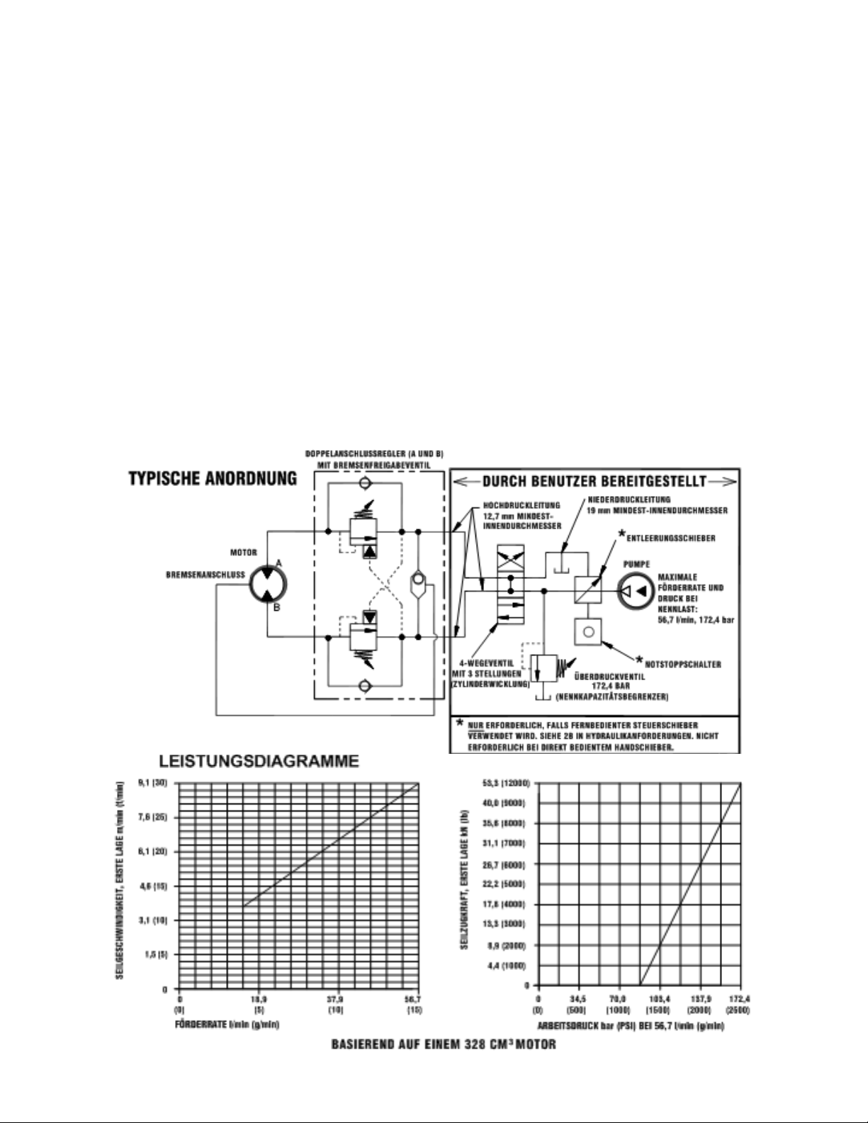
Zur richtigen Wahl der Hydraulik für die Leistung der Winde ist auf die folgenden Leistungsdiagramme Bezug zu
nehmen. Die Diagramme zeigen: (1) Seilzugkraft (kN), erste Lage im Vergleich zum Arbeitsdruck (bar) (2)
Seilgeschwindigkeit, erste Lage (m/min) im Vergleich zur Förderrate (l/min).
HYDRAULIKANFORDERUNGEN
1. Wegeventil (Motor-Durchflusssystem) erforderlich
2. Notstopp:
A. Falls Winde durch einen direktbedienten Handschieber gesteuert wird, funktioniert dieser Schieber als
Notstopp.
B. Wenn ein fernbedienter Steuerschieber verwendet wird, sind ein magnetgesteuerter hydraulischer
Entleerungsschieber (normalerweise gegen den Tank geöffnet) und ein Notstoppschalter (zum Öffnen des
Entleerungsschiebers) erforderlich. Der Notstoppschalter ist ein Öffnerkontakt und hat einen roten,
rücksetzbaren Druckknopfschalter mit gelbem Hintergrund. Der Notstoppschalter muss für den Bediener
einfach zugänglich sein.
3. Überdruckventil auf 172,4 bar eingestellt, entspricht dem Nennkapazitätsbegrenzer.
4. Maximale Förderrate von 56,7 l/min. 75,7 l/min nicht überschreiten, das ansonsten Motor und Winde
beschädigt werden können.
5. Hydrauliköl mit einer Viskosität zwischen 20-43 cSt (100-200 SUS). Maximale Betriebstemperatur 85 °C.
Sauberkeitsstufe ISO 17-14 oder besser.
39
Page 41

ZUSTAND MÖGLICHE URSACHE ABHILFE/MASSNAHME
TROMMEL DREHT SICH
NICHT - OHNE LAST
Winde nicht gerade montiert, wodurch das Endlager
eingeklemmt wird.
Zusammenbau überprüfen. Siehe Installation der Winde auf
Seite 38.
Zahnräder beschädigt. Beschädigte Zahnräder inspizieren und ggf. ersetzen.
TROMMEL DREHT SICH
NICHT - MIT LAST
Winde nicht gerade montiert, wodurch das Endlager
eingeklemmt wird.
Zusammenbau überprüfen.Siehe Installation der Winde
auf Seite 38.
Last ist höher als die Nennkapazität der Winde. Die nominale Seilzugkraft ist den technischen Daten auf
Seite 37 zu entnehmen.
Niedriger Hydraulikdruck.
Druck überprüfen. Siehe Hydraulik-Leistungsdiagramme auf
Seite 40.
DIE WINDE LÄUFT ZU
LANGSAM
Niedrige Hydraulikförderrate. Förderrate überprüfen. Siehe Systemvoraussetzungen und
typische Anordnung auf Seite 40.
Motor ist abgenutzt. Motor ersetzen.
KEIN FREILAUF AN DER
TROMMEL
Kupplung nicht ausgerückt. Einstellung der handbetätigten
Kupplung überprüfen (siehe Seite 43).
Funktion überprüfen (siehe Seite 39).
Winde nicht gerade montiert, wodurch das Endlager
eingeklemmt wird.
Zusammenbau überprüfen. Siehe Installation der Winde auf
Seite 38.
Seitliche Befestigungsschrauben sind zu lang und
verursachen eine Einklemmung des Hohlrads
(Nr. 18, Seite 47).
Schraubenlänge überprüfen. Das Schraubengewinde DARF
NICHT mehr als 12,7-17,5 mm in die Gewindebohrungen
in den Seiten des Endlagers eingreifen.
BREMSE HÄLT NICHT Falsches Wegeventil
(Zylinderwicklung - Durchflusssystem)
Nur ein Durchfluss-Wegeventil (Motorwicklung)
verwenden.
DIE LAST VERSCHIEBT SICH Zu hoher Gegendruck (max. 6,9 bar). Hydrauliksystem auf Blockierungen überprüfen. Siehe
Systemvoraussetzungen und typische Anordnung auf
Seite 40.
SEIL VERWICKELT SICH BEI
AUSGERÜCKTER
KUPPLUNG
Widerstandsschraube falsch eingestellt. Die Nylon-Widerstandsschraube justieren. Siehe Installation
des Seils auf Seite 38.
STARKE GERÄUSCHE Hydraulikförderrate zu hoch. Förderrate überprüfen. Siehe typische Anordnung auf
Seite 40.
Trommel klemmt, da Winde nicht gerade montiert ist.
Zusammenbau überprüfen. Siehe Installation der Winde auf
Seite 38.
TROMMEL RATTERT, IN
AUFWICKELRICHTUNG
Niedrige Hydraulikförderrate. Förderrate überprüfen. Siehe typische Anordnung auf
Seite 40.
Zu niedrige Hydrauliküberdruckeinstellung. Einstellung des Überdruckventils überprüfen.
ÖLLECK AUS DEM
ENTLÜFTER UNTER DEM
MOTORENDLAGER
O-Ringe der Bremse, Stützringe oder Dichtflächen
beschädigt.
Die Bremse demontieren und überprüfen. Siehe
Überholungsanweisungen auf Seite 42.
41
FEHLERSUCHE
Page 42

AUSSERBETRIEBSETZUNG
Die Winde am Ende ihrer Brauchbarkeitszeit gemäß örtlichen Umweltvorschriften entsorgen.
ÜBERHOLUNGSANWEISUNGEN FÜR DIE WINDEN DER MODELLREIHE RPH 53,3
Auf die Zusammensetzung der Teile achten, damit diese wieder richtig zusammengebaut werden. Alle Dichtringe,
O-Ringe und Dichtungen müssen beim Wiederzusammenbau ersetzt werden.
Das Rohr (Nr. 44) aus den Kniestücken (Nr. 24) am Boden der
Bremse (Nr. 6) und des Ventils (Nr. 45) trennen. Den Motor
(Nr. 31) aus dem Bremsengehäuse (Nr. 6) ausbauen. Dazu die
Kopfschrauben (Nr. 15) entfernen. Zum Lösen leicht auf den
Motor klopfen. Alle Dichtringe, O-Ringe und Dichtungen
müssen beim Wiederzusammenbau ersetzt werden.
Die Kupplung (Nr. 23) aus dem Bremsengehäuse ausbauen.
Die Kupplung auf Anzeichen von Verschleiß prüfen und bei
Bedarf ersetzen. Falls notwendig, das Ventil (Nr. 45) aus dem
Motor ausbauen. Dazu die Kopfschrauben (Nr. 18) und die
Sicherungscheiben (Nr. 49) entfernen. Beim Ausbau des
Ventils darauf achten, dass die zwei Vierkantdichtungsringe in
ihren Senkbohrungen im Ventil bleiben.
Zum Ausbau des Bremsengehäuses (Nr. 6) aus dem Endlager
(Nr. 4) die sechs (6) Kopfschrauben (Nr. 14) über Kreuz
(jeweils 2 Drehungen) lösen, bis alle Kopfschrauben vom
Bremsengehäuse entfernt sind. Die Bremsenteile aus dem
Bremsengehäuse ausbauen. Die Bremsscheiben (Nr. 26) auf
Anzeichen von Verschleiß überprüfen und bei Bedarf ersetzen.
Die O-Ringe (Nr. 34 und 35) und die Stützringe (Nr. 36 und
37) auf Anzeichen von Verschleiß überprüfen.
Die O-Ringe und Stützringe aus den Rillen im Bremskolben
(Nr. 3) entfernen.
Die Federn (Nr. 42 und 43) entfernen, auf Beschädigungen
überprüfen und bei Bedarf ersetzen.
Die Verschraubungen (Nr. 30) überprüfen, deren guten
Zustand bestätigen und bei Bedarf ersetzen.
Durch Entfernen der Kopfschrauben (Nr. 16) die
Verbindungsplatten (Nr. 9) aus den Endlagern (Nr. 4 und 5)
ausbauen. Den Sprengring (Nr. 41) und die Anlaufscheibe
(Nr. 48) von der Welle abziehen. Das Motorendlager (Nr. 4)
aus der Trommel (Nr. 1) und die Trommel aus dem
Getriebekasten-Endlager (Nr. 5) ziehen.
Die Antriebswelle (Nr. 8) und die Anlaufscheibe (Nr. 47) vom
Endlager abziehen. Die Zahnradzähne und Wellenkeile auf
Anzeichen von Verschleiß überprüfen. Wenn Beschädigungen
vorliegen, muss die Welle ersetzt werden.
41
Page 43

Den O-Ring (Nr. 32), die Buchse (Nr. 12) von der Außenseite des
Motorendlagers (Nr. 4), den O-Ring (Nr. 33), das Lager (Nr. 11) von der
Innenseite des Motorendlagers (Nr. 4) abnehmen. Einen neuen, gut geölten
O-Ring (Nr. 33) in die Rille im Endlager drücken und das neue Lager (Nr. 11)
in das Endlager pressen. Die Buchse (Nr. 12) auf das Endlager pressen, den
O-Ring (Nr. 32) in Öl eintauchen und in die Rille des Endlagers einpressen.
Die Dichtung (Nr. 40) aus dem Getriebekasten-Endlager (Nr. 5) ausbauen. Die
Mutter (Nr. 21) lösen, die Nylonstellschraube (Nr. 18) und das Hohlrad (Nr. 29)
vom Getriebekasten-Endlager abnehmen (falls notwendig). Die Buchse (Nr. 13)
und das Lager (Nr. 10) aus dem Getriebekasten-Endlager (Nr. 5) ausbauen.
Die neue Buchse (Nr. 13) und das Lager (Nr. 10) in das Endlager pressen.
Hohlrad, Nylonstellschraube und Mutter wieder anbringen. Das Hohlrad muss
vollständig im Getriebekasten-Endlager (Nr. 5) sitzen und der Schlitz im
Hohlrad DARF NICHT auf das Loch des Kupplungshebels ausgerichtet sein.
Eine neue Dichtung in das Getriebekasten-Endlager einbauen, wobei die
scharfe Kante der Dichtung nach außen gerichtet sein muss.
Reichlich Schmierfett (MOBILITH SHC 007) auf die Zähne des Hohlrads (Nr. 29), die Zähne des Planetenrads in der Trommel (Nr. 1) und die Buchse im
Getriebekasten-Endlager (Nr. 5) auftragen. Eine kleine Menge Schmierfett auf den Boden der Buchse auf dem Motorendlager (Nr. 4) auftragen. Auf die Zähne des
Zahnrads und das kurze Wellenende (Nr. 8) Schmierfett auftragen. Das zahnradseitige Ende der Welle durch die Anlaufscheibe (Nr. 47) und in das Lager im Endlager
(Nr. 5) schieben. Die Trommel auf die Welle setzen und die Trommel drehen, um die Planetenräder mit dem Abtriebszahnrad auf der Welle und dem Hohlrad im
Endlager in Eingriff zu bringen.
Das Motorendlager (Nr. 4) an die Trommelbaugruppe anbauen und die Verbindungsplatten (Nr. 9) und Kopfschrauben (Nr. 16) anbringen, um beide Endlager
zusammenzuhalten. Die Kopfschrauben auf 75 Nm festziehen. Die Anlaufscheiben (Nr. 48) auf die Welle und bis an das Endlager (Nr. 4) schieben. Den Sprengring
(Nr. 41) in die Rille im Keilende der Welle drücken.
Falls erforderlich, die Kupplungshebelbaugruppe (Nr. 2 oder 3) wie folgt ausbauen und ersetzen:
HANDBETÄTIGTER KUPPLUNGSHEBEL
Die Stellschraube (Nr. 19) und Gegenmutter lösen und die Baugruppe des handbetätigten Kupplungshebels (Nr. 2) abschrauben. Darauf achten, dass der Schlitz im
Hohlrad nicht auf das Loch im Kupplungshebel ausgerichtet ist. Falls notwendig, die Trommel drehen, damit das Loch und der Schlitz nicht aufeinander
ausgerichtet sind.
Die Kupplungshebelbaugruppe mit Kolben und Gegenmutter einbauen, wobei der Hebelgriff wie unten gezeigt im Getriebekasten positioniert sein muss. Die
Baugruppe (bei in den Zylinderschlitz eingreifendem Griff) in den Getriebekasten schrauben. Die Trommel in Richtung Getriebe-Endlager-Gehäuse ziehen, um
jegliches Spiel zu entfernen. Die Trommel festhalten und den Kupplungshebel weiter einschrauben, bis der Spalt zwischen dem Ende des Griffes und dem Zylinder
11,1 mm
+0
-1,6
mm beträgt und der Hebelgriff horizontal steht (siehe unten). Anmerkung: Dieser Spalt ist je nach dem Axialspiel der Trommel unterschiedlich. Bei
ganz gegen den Motorkasten gezogener Trommel sollte der Spalt 10 mm breit sein.
Die Gegenmutter leicht anziehen. Die Trommel drehen, bis der Hebelgriff vollständig in der eingerückten Position einrastet. Den Hebelgriff herausziehen und
um 90º drehen. Während sich der Kupplungshebel in der
AUSGERÜCKTEN Stellung befindet, überprüfen, ob sich die Trommel
unbehindert drehen lässt (mindestens eine volle Umdrehung). Den
Hebelgriff festhalten und die Gegenmutter festziehen. Die
Stellschraube (Nr. 19) festziehen. Die Funktion der Kupplung gemäß
den Anweisungen auf Seite 39 erneut prüfen.
PNEUMATISCHER KUPPLUNGSHEBEL
Die Stellschraube (Nr. 19) lösen, um die Kupplungshebelbaugruppe
(Nr. 3) zu entfernen. Zum Wiedereinbau 1 oder 2 Passscheiben
(Nr. 44) auf den Kolben legen und die Kupplungshebelbaugruppe in
den Getriebekasten schrauben. Je nach Bedarf Passscheiben
hinzufügen oder entfernen, um die Baugruppe für die
Druckluftanschlüsse auszurichten. Die Anschlüsse sollten nach
unten zeigen (unterhalb der Horizontalebene). Die Stellschraube
festziehen. Die Funktion der Kupplung gemäß den Anweisungen auf
Seite 39 prüfen.
Wenn die Lampe (Nr. 2) oder der Lampenschalter (Nr. 48) ersetzt
werden müssen, auf das Anschlussdiagramm auf Seite 46 Bezug
nehmen und wie gezeigt demontieren und wieder einbauen.
42
Page 44

Die Winde so auf den Getriebekasten setzen, dass das Motorendlager (Nr. 4) oben ist. Sechs (6) Federn (Nr. 42) wie gezeigt in
die Taschen im Motorendlager (Nr. 4) stecken und die oberste und unterste Tasche frei lassen. Die Kupplung (Nr. 23) auf das
Keilende der Welle (Nr. 8) schieben. Vier (4) Bremsbolzen (Nr. 7) in die vier (4) Bohrungen im Motorendlager stecken. Die gut
geölten O-Ringe (Nr. 34 und 35) und Stützringe (Nr. 36 und 37) in die außenliegenden Rillen des Kolbens (Nr. 3) drücken. In
beiden Fällen die O-Ringe in die Rillen einsetzen, die der
Kolbenmitte am nächsten liegen. Siehe QUERSCHNITT A-A unten.
Kolben (Nr. 3), Bremsscheibe (Nr. 26) und Trennplatten
(Nr. 39) müssen sauber und frei von Schmierfett und Öl sein.
Den Kolben (Nr. 7) auf die Federn (Nr. 42) setzen. Die
Trennplatten (Nr. 39) und die Bremsscheiben wie unten gezeigt
abwechselnd auf den Kolben aufbringen. Das weitere Ende (4)
der Federn (Nr. 43) in die Taschen im Bremsengehäuse (Nr. 6)
stecken. Den Dichtring (Nr. 27) auf das Endlager (Nr. 4) legen.
Das Bremsengehäuse auf die Bremsenteile setzen, wobei die
Anschlussverschraubungen nach unten zu den Füßen gerichtet
sein müssen. Die Montagebohrungen ausrichten und das
Bremsengehäuse auf das Endlager (Nr. 4) pressen. Etwas
271 Loc-tite auf die 6 Kopfschrauben (Nr. 14) auftragen, die
Schrauben handfest anziehen, sodass sie oberflächenbündig
mit dem Bremsengehäuse abschließen. Die Kopfschrauben
über Kreuz (jeweils 2 Umdrehungen) auf 41 Nm pro
Kopfschraube festziehen.
Den Dichtring (Nr. 28) auf die Anbaufläche des Motors (Nr. 31) legen. Die Motorwelle in die Kupplung schieben und den Motor
am Bremsengehäuse (Nr. 6) befestigen. Zwei (2)
Kopfschrauben (Nr. 15) mit Sicherungsscheiben
(Nr. 22) anbringen und auf 118 Nm festziehen.
Das Rohr (Nr. 44) sicher am Kniestück (Nr. 24),
im Ventil (Nr. 45) und unten im Bremsengehäuse
(Nr. 6) anschließen.
Mindestens 37,9 bar Hydraulikdruck anlegen,
um die Bremse zu lösen, und durch Beobachten
der Seiltrommeldrehung prüfen, ob sich die
Bremse löst.
43
Page 45

44
RPH 53,3 HANDBETÄTIGTER KUPPLUNGSHEBEL
Page 46

45
RPH 53,3 PNEUMATISCHER KUPPLUNGSHEBEL
Page 47

46
RPH 53,3 HANDBETÄTIGTER KUPPLUNGSHEBEL
Page 48

47
TEILELISTE FÜR RPH 53,3 MIT HANDBETÄTIGTEM KUPPLUNGSHEBEL
LFD. NR. ANZ. TEILE-NR. BESCHREIBUNG
1 1 234226 TROMMELBAUGRUPPE
2 1 276052 KUPPLUNGSHEBELBAUGRUPPE, HANDBETÄTIGT
3 1 296611 ENDLAGER - MOTOR
4 1 306042 KOLBEN - BREMSE
5 1 334177 HOHLRAD
6 1 338297 GETRIEBEKASTEN, ENDLAGER
7 1 338302 GEHÄUSE - BREMSE
8 NICHT VERWENDET
9 4 346045 BOLZEN - BREMSE
10 1 357518 WELLE - ANTRIEB
11 2 395236 VERBINDUNGSPLATTE
12 1 402120 LAGER
13 1 402121 LAGER - MOTOR-ENDLAGER
14 1 412095 BUCHSE - TROMMEL (MOTORSEITIG)
15 1 412096 BUCHSE - TROMMEL (GETRIEBEKASTENSEITIG)
16 4 414159 KOPFSCHRAUBE - 5/16-18 x 38 mm LANG, SECHSKANT, SORTE 5, VERZINKT
17 6 414303 KOPFSCHRAUBE - 3/8-16NC x 63 mm LANG, SECHSKANT, SORTE 5, PLATTIERT
18 8 414664 KOPFSCHRAUBE - 5/8-11NC x 25 mm LANG, SECHSKANT, SORTE 5
19 1 414926 STELLSCHRAUBE - 3/8-16NC x 25 mm LANG, INBUS, NYLON
20 2 414948 KOPFSCHRAUBE - 1/2-13NC x 32 mm LANG, INBUS
21 1 315009 SEILANKER
22 1 418036 MUTTER - 3/8-16NC, SECHSKANT, GEGENMUTTER
23 4 418063 SICHERUNGSSCHEIBE - 5/16, GETEILT, VERZINKT
24 2 418218 SICHERUNGSSCHEIBE - 1/2 ID, GETEILT
25 1 431015 KUPPLUNG - BREMSE
26 2 432018 VERSCHRAUBUNG - 7/16, KNIESTÜCK
27 4 438022 SCHEIBE - BREMSE
28 1 442220 DICHTRING - BREMSE
29 1 442223 DICHTRING - MOTOR
30 1 456038 ENTLÜFTERVENTIL
31 1 458171 MOTOR - HYDRAULIK
32 1 462056 O-RING
33 1 462057 O-RING
34 1 462058 O-RING
35 1 462059 O-RING
36 1 462060 O-RING
37 1 462061 O-RING (TROMMEL)
38 1 472052 VERSCHLUSSSCHRAUBE/STOPFEN
39 5 474111 TRENNPLATTE
40 1 486081 DICHTUNG - GETRIEBEKASTEN
41 1 490037 SEEGERRING
42 6 494110 FEDER - BREMSE
43 4 494112 FEDER
44 1 509143 ROHR, KOMPLETT
45 1 516055 STEUERSCHIEBER, MOTOR
46 1 518037 ANLAUFSCHEIBE
47 1 518047 ANLAUFSCHEIBE
48 1 518052 ANLAUFSCHEIBE
49 1 518053 ANLAUFSCHEIBE (MOTORSEITIG)
50 1 518054 ANLAUFSCHEIBE (GETRIEBEKASTENSEITIG)
51 1 434573 TYPEN- UND DATENSCHILD
Page 49

48
RPH 53,3 PNEUMATISCHER KUPPLUNGSHEBEL
Page 50

49
TEILELISTE FÜR RPH 53,3 MIT PNEUMATISCHEM KUPPLUNGSHEBEL
LFD. NR. ANZ. TEILE-NR. BESCHREIBUNG
1 1 234226 TROMMELBAUGRUPPE
2 1 236020 LAMPENBAUGRUPPE
3 1 276053 KUPPLUNGSHEBELBAUGRUPPE, PNEUMATISCH
4 1 296611 ENDLAGER - MOTOR
5 1 306042 KOLBEN - BREMSE
6 1 312526 HALTERUNG - LAMPENMONTAGE
7 1 334177 HOHLRAD
8 1 338297 GETRIEBEKASTEN, ENDLAGER
9 1 338302 GEHÄUSE - BREMSE
10 4 346045 BOLZEN - BREMSE
11 1 357518 WELLE - ANTRIEB
12 2 395236 VERBINDUNGSPLATTE
13 1 402120 LAGER
14 1 402121 LAGER - MOTOR-ENDLAGER
15 1 412095 BUCHSE - TROMMEL (MOTORSEITIG)
16 1 412096 BUCHSE - TROMMEL (GETRIEBEKASTENSEITIG)
17 2 414036 KOPFSCHRAUBE - 1/4-20NC X 13 mm, SECHSKANT, SORTE 5, SCHWARZ
18 4 414159 KOPFSCHRAUBE - 5/16-18 x 38 mm LANG, SECHSKANT, SORTE 5, VERZINKT
19 6 414303 KOPFSCHRAUBE - 3/8-16NC x 63 mm LANG, SECHSKANT, SORTE 5, PLATTIERT
20 8 414664 KOPFSCHRAUBE - 5/8-11NC x 25 mm LANG, SECHSKANT, SORTE 5
21 1 414926 STELLSCHRAUBE - 3/8-16NC x 25 mm LANG, INBUS, NYLON
22 2 414948 KOPFSCHRAUBE - 1/2-13NC x 32 mm LANG, INBUS
23 1 315009 SEILANKER
24 1 418036 MUTTER - 3/8-16NC, SECHSKANT, GEGENMUTTER
25 4 418063 SICHERUNGSSCHEIBE - 5/16, GETEILT, VERZINKT
26 2 418218 SICHERUNGSSCHEIBE - 1/2 ID, GETEILT
27 1 431015 KUPPLUNG - BREMSE
28 2 432018 VERSCHRAUBUNG - 7/16, KNIESTÜCK
29 4 438022 SCHEIBE - BREMSE
30 1 442220 DICHTRING - BREMSE
31 1 442223 DICHTRING - MOTOR
32 1 456038 ENTLÜFTERVENTIL
33 1 458171 MOTOR - HYDRAULIK
34 1 462056 O-RING
35 1 462057 O-RING
36 1 462058 O-RING
37 1 462059 O-RING
38 1 462060 O-RING
39 1 462061 O-RING (TROMMEL)
40 5 474111 TRENNPLATTE
41 1 482013 TÜLLE
42 1 482045 GUMMIMANSCHETTE
43 1 486081 DICHTUNG - GETRIEBEKASTEN
44 2 488007 PASSSCHEIBE
45 1 490037 SEEGERRING
46 6 494110 FEDER - BREMSE
47 4 494112 FEDER
48 1 504021 SCHALTERBAUGRUPPE
49 1 509143 ROHR, KOMPLETT
50 1 516055 STEUERSCHIEBER, MOTOR
51 1 518047 ANLAUFSCHEIBE
52 1 518052 ANLAUFSCHEIBE
53 1 518053 ANLAUFSCHEIBE (MOTORSEITIG)
54 1 518054 ANLAUFSCHEIBE (GETRIEBEKASTENSEITIG)
55 1 434575 TYPEN- UND DATENSCHILD
Page 51

MANUAL DE FUNCIONAMIENTO,
REPARACIÓN Y MANTENIMIENTO
CABESTRANTE PLANETARIO MODELO RPH 53,3
PRECAUCIÓN: LEER Y ENTENDER ESTE MANUAL ANTES DE INSTALAR Y OPERAR EL
CABESTRANTE. OBSERVAR LAS ADVERTENCIAS.
English . . . . . . . . . . . . . . . . . . . . .1
Français . . . . . . . . . . . . . . . . . . .19
Deutsch . . . . . . . . . . . . . . . . . . .34
Español . . . . . . . . . . . . . . . . . . .50
Ramsey Winch Company
P.O. Box 581510 - Tulsa, OK 74158-1510 EE.UU.
Teléfono: + 1 918 438-2760 - Fax: +1 918 438-6688
Visítenos en http://www.ramsey.com
OM-914215-1012-BA
USO PRETENDIDO: RECUPERACIÓN DE VEHÍCULOS Y ARRASTRE DE CARGAS
Page 52

CONTENIDO
INTRODUCCIÓN
. . . . . . . . . . . . . . . . . . . . . . . . . . . . . . . . . . . . . . . . . . . . . . . . . . . . . . . . . . . . . . . . . . . . .54
ESPECIFICACIONES . . . . . . . . . . . . . . . . . . . . . . . . . . . . . . . . . . . . . . . . . . . . . . . . . . . . . . . . . . . . . . . . . . . .54
ADVERTENCIAS . . . . . . . . . . . . . . . . . . . . . . . . . . . . . . . . . . . . . . . . . . . . . . . . . . . . . . . . . . . . . . . . . . . . . . .54
RESPONSABILIDAD DEL USUARIO PARA EL CUMPLIMIENTO CON LAS DISPOSICIONES CE . . . . . . . . . . . . .54
MONTAJE DEL CABESTRANTE . . . . . . . . . . . . . . . . . . . . . . . . . . . . . . . . . . . . . . . . . . . . . . . . . . . . . . . . . . .55
INSTALACIÓN DE CABLE METÁLICO . . . . . . . . . . . . . . . . . . . . . . . . . . . . . . . . . . . . . . . . . . . . . . . . . . . . . . .55
MANTENIMIENTO . . . . . . . . . . . . . . . . . . . . . . . . . . . . . . . . . . . . . . . . . . . . . . . . . . . . . . . . . . . . . . . . . . . . .56
FUNCIONAMIENTO . . . . . . . . . . . . . . . . . . . . . . . . . . . . . . . . . . . . . . . . . . . . . . . . . . . . . . . . . . . . . . . . . . . .56
REQUISITOS DEL SISTEMA HIDRÁULICO . . . . . . . . . . . . . . . . . . . . . . . . . . . . . . . . . . . . . . . . . . . . . . . . . . .57
GRÁFICOS DE FUNCIONAMIENTO . . . . . . . . . . . . . . . . . . . . . . . . . . . . . . . . . . . . . . . . . . . . . . . . . . . . . . . . .57
GUÍA DE SOLUCIÓN DE PROBLEMAS . . . . . . . . . . . . . . . . . . . . . . . . . . . . . . . . . . . . . . . . . . . . . . . . . . . . . .58
MEDIDAS CUANDO TERMINA LA VIDA ÚTIL . . . . . . . . . . . . . . . . . . . . . . . . . . . . . . . . . . . . . . . . . . . . . . . . .59
INSTRUCCIONES DE VERIFICACIÓN . . . . . . . . . . . . . . . . . . . . . . . . . . . . . . . . . . . . . . . . . . . . . . . . . . . . .59-61
DIBUJOS ACOTADOS . . . . . . . . . . . . . . . . . . . . . . . . . . . . . . . . . . . . . . . . . . . . . . . . . . . . . . . . . . . . . . . .62-63
LISTA DE PIEZAS Y DIBUJOS DE PIEZAS . . . . . . . . . . . . . . . . . . . . . . . . . . . . . . . . . . . . . . . . . . . . . . . . .64-67
DECLARACIÓN CE DE CONFORMIDAD . . . . . . . . . . . . . . . . . . . . . . . . . . . . . . . . . . . . . . . . . . . . . . . . . . . . .68
Page 53
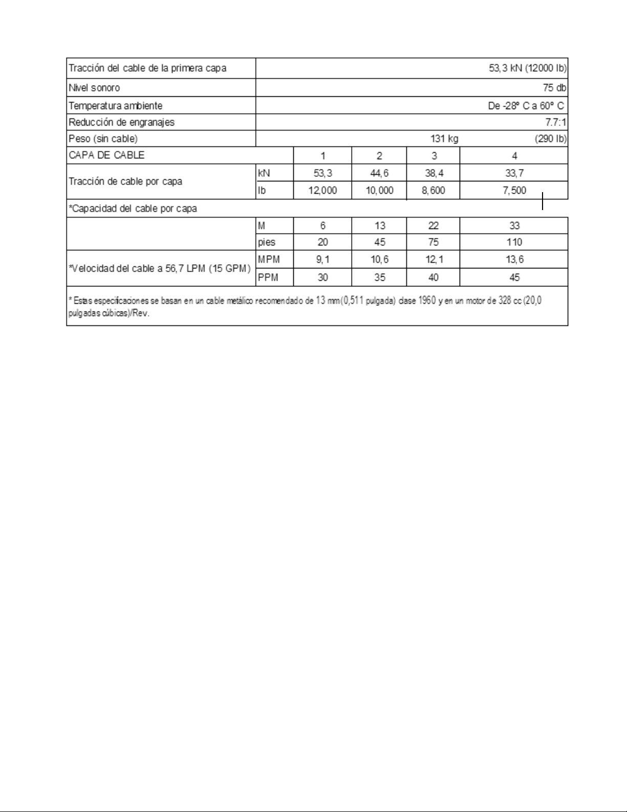
ESPECIFICACIONES*
ADVERTENCIAS:
EL USUARIO DEBERÁ GARANTIZAR QUE EL PERSONAL QUE OPERE EL EQUIPO HAYA RECIBIDO LA FORMACIÓN NECESARIA.
EL OPERADOR DEBERÁ TRABAJAR SIEMPRE SIGUIENDO LAS INSTRUCCIONES DE FUNCIONAMIENTO.
PARA EL FUNCIONAMIENTO DEL FRENO SE REQUIERE UNA VÁLVULA DE CONTROL DIRECCIONAL (CON ENSANCHE EN
EL CENTRO) DE LA BOBINA DEL MOTOR.
EL EMBRAGUE DEBE ESTAR TOTALMENTE ENGRANADO ANTES DE COMENZAR A MANEJAR EL CABESTRANTE.
NO DESENGRANAR EL EMBRAGUE BAJO CARGA.
NO ACERCARSE A LAS CARGAS ELEVADAS.
NO ACERCARSE AL CABLE METÁLICO CUANDO ESTÉ TIRANDO. NO INTENTAR GUIAR EL CABLE METÁLICO.
NO UTILIZAR EL CABESTRANTE PARA LEVANTAR, SUJETAR O TRANSPORTAR PERSONAS.
PARA SUJETAR LA CARGA SE NECESITA UN MÍNIMO DE 2 VUELTAS DE CABLE METÁLICO ALREDEDOR DEL CUERPO
DEL TAMBOR.
EN APLICACIONES DE TRANSPORTE DE VEHÍCULOS, DESPUÉS DE SUBIR EL VEHÍCULO AL TRANSPORTADOR,
ASEGURARSE DE FIJARLO A LA CAJA. NO MANTENER LA CARGA EN EL CABLE DEL CABESTRANTE CUANDO SE ESTÉ
TRANSPORTANDO EL VEHÍCULO. NO EMPLEAR EL CABESTRANTE COMO AMARRA.
EVITAR LAS CONDICIONES EN LAS QUE SE PUEDA PRODUCIR LA SACUDIDA O EL DESPLAZAMIENTO DE LA CARGA.
DEBERÁ EVITARSE EL BALANCEO EXCESIVO.
RESPONSABILIDAD DEL USUARIO PARA EL CUMPLIMIENTO CON LAS DISPOSICIONES CE
1. Emplear solamente una válvula de control (con ensanche en el centro) de la bobina del motor que sea conforme
a los requisitos del sistema hidráulico.
2. Si se usa una válvula de control del cabestrante accionada de forma remota, consultar la sección de requisitos
del sistema hidráulico para conocer los componentes de parada de emergencia que es necesario instalar.
3. Ajustar la presión de alivio del sistema conforme a lo descrito en la sección de requisitos del sistema hidráulico.
4. Montar el cabestrante según las instrucciones de montaje del cabestrante.
5. Instalar el cable metálico de 13 mm de clase 1960. La longitud máxima del cable debe ser de 33 m para un
máximo de cuatro capas. Conectar el cable al tambor según las instrucciones de instalación del cable. El gancho
debe tener un cierre de seguridad y una resistencia mínima a la ruptura de 133 kN.
52
Page 54
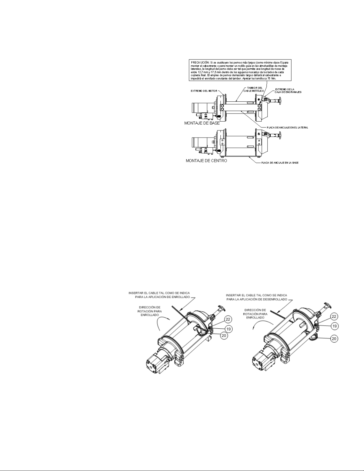
MONTAJE DEL CABESTRANTE
INSTRUCCIONES DE MONTAJE FUNDAMENTALES PARA ALINEAR LOS COMPONENTES DEL CABESTRANTE PLANETARIO:
Es de suma importancia que este cabestrante se monte
firmemente de forma que las tres secciones principales
(el extremo del motor, el tambor del cable y el extremo
de la caja de engranajes) queden alineadas
correctamente. Un desgaste excesivo del manguito y la
dificultad a la hora de desenrollar libremente el cable
son síntomas habituales de desalineación.
Cuando está instalado, si el cabestrante está montado
en el centro entonces deberá conectarse por lo menos
una placa de anclaje con los pies de montaje de la
parte inferior del cabestrante para mantener la
alineación. Si el cabestrante está montado sobre
pedestal, entonces al menos una placa de anclaje
deberá permanecer montada en el punto central del
cabestrante para mantener la alineación. Siempre es
preferible emplear AMBAS placas de anclaje en la
configuración final de instalación.
Cuando se monte el cabestrante, habrá que emplear
los patrones de agujeros de montaje descritos en los dibujos acotados de las páginas 62-63. La superficie de montaje debe ser plana dentro
del los 0,38 mm y lo suficiente rígida como para resistir la flexión. Si se emplea una placa de acero para el montaje sobre pedestal, deberá
tener un grosor de 19 mm. Para esta aplicación de montaje se necesitarán ocho (8) tornillos de casquete 1/2-13NC X 1-1/2 pulg. de largo
clase 5 con arandelas de seguridad para montar el cabestrante. Los tornillos de casquete deben apretarse a un par de torsión de 235 Nm.
NOTA: Si se emplean las escuadras o la placa de acero para montar el cabestrante, habrá que conectar las placas de anclaje provistas con
el cabestrante a las almohadillas de montaje, ya sean laterales o de pedestal.
INSTALACIÓN DE CABLE METÁLICO
1. Desenrollar el cable extendiéndolo sobre el suelo para evitar el retorcimiento. Envolver firmemente el extremo del cable, opuesto al
gancho, con cinta plástica o similar para evitar que se deshilache.
2. Deslizar el cable metálico a través del
extremo estrecho del receptáculo junto al
reborde del tambor. Enrollar el cable
metálico alrededor del retenedor
(elemento núm. 20), tirar de aquél y
anclarlo de vuelta en el extremo ancho
del receptáculo. Emplear un martillo
blando para dirigir el lado posterior del
cable metálico, asentando éste último y
el anclaje firmemente en el receptáculo.
3. Hacer funcionar con cuidado el
cabestrante en la dirección de subida
con el carrete. Manteniendo la tensión en
el extremo del cable, enrollar todo el
cable en el tambor del cable, teniendo
cuidado de formar capas bien envueltas.
Después de instalar el cable, comprobar el
funcionamiento de enrollado constante. Desengranar el embrague y tirar del cable a una
velocidad de paso lento. Si el cable se sale, aflojar la contratuerca (elemento núm. 22) y girar el tornillo fijador de nilón (elemento núm. 17)
hacia la derecha para aumentar el arrastre en el tambor. Si la tracción del cable es excesiva, aflojar el tornillo fijador de nilón girándolo hacia
la izquierda. Apretar la contratuerca cuando se consiga el ajuste adecuado.
PRECAUCIÓN: SI SE APRIETA DEMASIADO LA CONTRATUERCA, EL TORNILLO FIJADOR DE NILÓN PODRÍA ROMPERSE.
53
Page 55

MANTENIMIENTO
1.
Inspeccionar el cable en busca de daños y lubricarlo con frecuencia. Si el cable se deshilacha con hilos rotos, cambiarlo inmediatamente.
2. Comprobar que el embrague esté totalmente engranado. Ver en las instrucciones de FUNCIONAMIENTO anteriores el embrague
apropiado. SOLAMENTE PARA EL EMBRAGUE MANUAL: Desenganchar el embrague mensualmente, poner varias gotas de aceite en el
eje del asa del mismo y METER y SACAR el asa del embrague varias veces para lubricar el conjunto del cambio.
3. Comprobar que el cable del tambor no se salga cuando se realice el enrollado libre. Si se sale, consultar la página 55.
4. Cambiar los manguitos del tambor y los sellos si empiezan a infiltrar grasa. Consultar la sección Instrucciones de verificación en las
páginas 59-61. Añadir más lubricante Mobilith SHC 007 a los engranajes y a los cojinetes del tambor si fuese necesario.
FUNCIONAMIENTO
La mejor manera de familiarizarse con el funcionamiento del cabestrante es hacer pruebas de funcionamiento antes de utilizarlo. Planee la
prueba con antelación. Tenga en cuenta que el cabestrante se puede oír, al igual que se puede ver cómo funciona. Hay que acostumbrarse a
reconocer los sonidos de una tracción ligera y continua, una tracción pesada, y el sonido producido por la sacudida o desplazamiento
de la carga. Evitar las condiciones en las que se pueda producir la sacudida o el desplazamiento de la carga, ya que podría suponer una
situación peligrosa.
El enrollado desigual del cable, mientras se está tirando de la carga, no es un problema, a menos que se produzca un apilamiento de cable
en un extremo del tambor. Si esto sucede, invertir el cabestrante para aliviar la carga y alejar el punto de anclaje del centro del vehículo.
Una vez acabado el trabajo, se puede desenrollar y enrollar para que el cable quede bien colocado.
Al tirar de una carga pesada, coloque una manta, chaqueta o lona sobre el cable 1,5 a 1,8 metros detrás del gancho. En el caso de que se
rompa el cable, disminuirá la velocidad del latigazo del cable y podrá evitar lesiones graves.
El embrague del cabestrante permite un desenrollado rápido del cable, desde el tambor del cable, para engancharse a una carga. La palanca
del embrague o el cambio de aire accionan el embrague.
ADVERTENCIA: NO DESENGRANAR EL EMBRAGUE BAJO CARGA.
DESEMBRAGUE MANUAL (Consultar el dibujo acotado en la página 62):
PARA DESENGRANAR EL EMBRAGUE: Hacer funcionar el cabestrante en marcha atrás (desenrollar) hasta que la carga se suelte del cable.
Tirar del asa hacia afuera y girarla 90º. Con el asa en la posición de “DESENGRANADO”, el cable se puede desenrollar hora constantemente
del tambor.
PARA ENGRANAR EL EMBRAGUE: Tirar del asa hacia afuera, girarla 90º y soltarla. Hacer funcionar el cabestrante en marcha atrás hasta que
el asa encaje totalmente en la posición de “ENGRANADO”. NO intentar tirar de una carga a menos que el asa esté en la posición
“ENGRANADA” totalmente. Si la luz indicadora del embrague manual está presente, la luz verde se enciende cuando el embrague está
totalmente “ENGRANADO”. NO intentar tirar de una carga a menos que la luz verde esté encendida. Para instalar la luz en el sistema eléctrico
del vehículo, consultar el Esquema eléctrico en la página 63.
DESEMBRAGUE DE CILINDRO DE AIRE (Consultar el dibujo acotado en la página 63):
PARA DESENGRANAR EL EMBRAGUE: Hacer funcionar el cabestrante en marcha atrás (desenrollar) hasta que la carga se suelte del cable.
Aplicar presión de aire al orificio 125-27 NPT: 5,5 bar (80 PSI) (mín.)- 10,3 bar (150 PSI) (máx.). PRECAUCIÓN: LA PRESIÓN NO DEBE
SOBREPASAR LOS 10,3 BAR (150 PSI).
PARA ENGRANAR EL EMBRAGUE: Quitar la presión de aire del cilindro (un resorte de retorno engancha el pistón). Hacer funcionar el
cabestrante en marcha atrás hasta que se encienda la luz indicadora de embrague engranado. Para instalar la luz en el sistema eléctrico del
vehículo, consultar el Esquema eléctrico en la página 63.
54
Page 56

Consultar las gráficas de funcionamiento a continuación para comparar correctamente el sistema hidráulico con el
funcionamiento del cabestrante. Las gráficas consisten en: (1) Tracción del cable kN (lbs.) de la primera capa en
función de la presión de trabajo bar (PSI). (2) Velocidad del cable, primera capa MPM (PPM) en función del flujo
LPM (GPM).
REQUISITOS DEL SISTEMA HIDRÁULICO
1. Válvula de control (con ensanche en el centro) de la bobina del motor
2. Parada de emergencia:
A. Si el cabestrante se controla con una válvula manual de accionamiento directo, dicha válvula servirá como
parada de emergencia.
B. Si se emplea una válvula de control de accionamiento remoto, se necesita una válvula de descarga
hidráulica accionada por solenoide, normalmente abierta al tanque, y un interruptor de parada de
emergencia (para abrir la válvula de descarga). El interruptor de parada de emergencia debe estar por lo
general cerrado y dispone de un accionador de botón reiniciable de color rojo con el fondo amarillo. El
interruptor de parada de emergencia debe estar ubicado de modo que el operador tenga fácil acceso al
mismo.
3. La válvula de alivio debe estar ajustada a 172,4 bares, valor que coincide con el limitador de capacidad
nominal.
4. La medida del caudal debe ser como máximo de 56,7 LPM. No se deben sobrepasar los 75,7 LPM; de lo
contrario, el motor y el cabestrante podrían dañarse.
5. El fluido hidráulico debe tener una viscosidad de 20 a 43 cSt (100 a 200 SUS). La temperatura de
funcionamiento máxima es de 85º C. El nivel de limpieza según la norma ISO debe ser 17-14 o mejor.
55
Page 57

ESTADO CAUSA POSIBLE CORRECCIÓN/ACCIÓN
EL TAMBOR NO GIRA SIN
CARGA
El cabestrante no está montado en ángulo recto,
haciendo que los cojinetes finales se traben
Comprobar el montaje. Consultar Montaje del
cabestrante en la página 55.
Engranajes dañados Inspeccionar y cambiar los engranajes dañados.
EL TAMBOR NO GIRA
BAJO CARGA
El cabestrante no está montado en ángulo recto,
haciendo que los cojinetes finales se traben
Comprobar el montaje. Consultar Montaje del
cabestrante en la página 55.
Carga mayor que la capacidad nominal del
cabestrante
Consultar Especificaciones en la página 54 para ver
la tracción del cable de régimen.
Presión baja del sistema hidráulico Comprobar la presión. Consultar los gráficos de
funcionamiento en Sistemas Hidráulicos, página 57.
EL CABESTRANTE
FUNCIONA DEMASIADO
LENTO
Medida del caudal baja del sistema hidráulico.
Comprobar la medida del caudal.
Comprobar la medida del caudal. Consultar Requisitos
del sistema y Disposición típica en la página 57.
Motor desgastado Cambiar el motor.
EL TAMBOR NO REALIZA
EL ENROLLADO
CONSTANTE
El embrague no se desengrana. Comprobar Ajuste
del desembrague en la página 60
Ver Funcionamiento en la página 56.
El cabestrante no está montado en ángulo recto,
haciendo que los cojinetes finales se traben
Comprobar el montaje. Consultar Montaje del
cabestrante en la página 55.
Los pernos de montaje lateral son demasiado
largos, haciendo que la corona dentada se trabe
(elemento núm. 18, página 64).
Comprobar la longitud del perno. La rosca del perno
NO DEBE engancharse en los agujeros roscados a
los lados del soporte final a una profundidad mayor
de entre 12,7 mm y 17,5 mm.
EL FRENO NO FRENA Válvula de control direccional incorrecta (bobina del
cilindro-centro cerrado)
Emplear solamente una válvula de control
(con ensanche en el centro) de la bobina del motor.
LA CARGA SE DESPLAZA Contrapresión excesiva 6,9 bar (100 PSI) máx. Comprobar si existen restricciones en el sistema
eléctrico. Consultar Requisitos del sistema y
Disposición típica en la página 57.
EL CABLE SE SALE
CUANDO SE DESENGRANA
EL EMBRAGUE
Tornillo de arrastre mal ajustado Ajustar el tornillo de llamada de nilón. Consultar
Instalación del cable metálico en la página 55.
RUIDO EXCESIVO Flujo del sistema hidráulico demasiado alto Comprobar la medida del caudal. Consultar
Disposición típica en la página 57.
Tambor trabado, el cabestrante no está montado en
ángulo recto
Comprobar el montaje. Consultar Montaje del
cabestrante en la página 54.
EL TAMBOR CHIRRÍA, EN
LA DIRECCIÓN DE SUBIDA
DE CARGA
Medida del caudal baja del sistema hidráulico Comprobar la medida del caudal. Consultar
Disposición típica en la página 57.
Ajuste bajo de la presión de alivio del sistema
hidráulico
Comprobar el ajuste de la válvula de desahogo.
FUGAS DE ACEITE DEL
AGUJERO DE VENTILACIÓN
BAJO EL COJINETE FINAL
DEL MOTOR
Juntas tóricas del freno, anillos de respaldo o
superficies obturadoras dañados
Desmontar el freno e inspeccionarlo. Ver las
Instrucciones de verificación en la página 59.
56
Page 58

MEDIDAS CUANDO TERMINA LA VIDA ÚTIL
Cuando el cabestrante llegue al final de su vida útil, desecharlo según las normativas medioambientales locales.
INSTRUCCIONES PARA VERIFICAR LOS CABESTRANTES DE LA SERIE RPH 53,3
Anotar las configuraciones de montaje para poder montar las piezas correctamente durante el remontaje. Durante
el remontaje cambiar todas las empaquetaduras, juntas tóricas y sellos.
Desconectar el tubo (elemento núm. 44) de los codos (elemento
núm. 24) en la parte inferior del freno (elemento núm. 6) y la válvula
(elemento núm. 45). Retirar el motor (elemento núm. 31) de la caja
del freno (elemento núm. 6) sacando los tornillos de casquete
(elemento núm. 15). Golpear el motor ligeramente para
desengancharlo. Durante el remontaje cambiar todas las
empaquetaduras, juntas tóricas y obturadores con otros nuevos.
Retirar el acoplamiento (elemento núm. 23) de la caja del freno.
Examinar el acoplamiento por si presenta señales de desgaste,
cambiarlo si fuese necesario. Si fuese necesario, quitar la válvula
(elemento núm. 45) del motor retirando los tornillos de casquete
(elemento núm. 18) y las arandelas de seguridad (elemento núm.
49). Si se quita la válvula, asegurarse de que las dos juntas tóricas
de la sección transversal cuadrada permanecen asentadas en los
agujeros escariados de la válvula.
Retirar la caja del freno (elemento núm. 6) del cojinete final
(elemento núm. 4) desatornillando los (6) tornillos de casquete
(elemento núm. 14) de forma cruzada (2 vueltas cada uno) hasta
retirarlos del todo. Retirar las piezas del freno de la caja del freno.
Examinar los discos del freno (elemento núm. 26) por si presentan
señales de desgaste y, reemplazarlos si fuese necesario. Examinar
las juntas tóricas (elementos núm. 34 y 35) y los anillos de
respaldo (elementos núm. 36 y 37) por si presentan señales
de desgaste.
Retirar las juntas tóricas y los anillos de respaldo de las ranuras del
pistón del freno (elemento núm. 3).
Retirar y examinar los muelles (elementos núm. 42 y 43) por si
están dañados y, cambiarlos si fuese necesario.
Examinar la conexión (elemento núm. 30) para asegurarse de las
conexiones estén en condiciones de funcionamiento correcto y
cambiarla si fuese necesario.
Retirar las placas de anclaje (elemento núm. 9) de los cojinetes
finales (elementos núm. 4 y 5) desatornillando los tornillos de
casquete (elemento núm. 16), tal como se muestra. Retirar del eje
el anillo sujetador (elemento núm. 41) y las arandelas de empuje
(elemento núm. 48). Deslizar el cojinete final del motor (elemento
núm. 4) del tambor (elemento núm. 1) y el tambor fuera del cojinete
final de la caja de engranajes (elemento núm. 5).
Retirar del cojinete final el eje de entrada (elemento núm. 8) y la
arandela de empuje (elemento núm. 47). Inspeccionar los dientes
del engranaje y el extremo ranurado del eje por si presentan señales
de desgaste. Si están dañados, será necesario cambiar el eje.
57
Page 59

Retirar la junta tórica (elemento núm. 32) y el manguito (elemento núm. 12)
del cojinete final (elemento núm. 4) del exterior del motor; retirar la junta
tórica (elemento núm. 33) y el manguito (elemento núm. 11) del cojinete
final (elemento núm. 4) del interior del motor. Poner una junta tórica
(elemento núm. 33) nueva y bien engrasada en la ranura dentro del
cojinete final y empujar un manguito (elemento núm. 11) nuevo sobre el
cojinete final. Presionar un nuevo manguito (elemento núm. 12) en el
cojinete final y sumergir la junta tórica (elemento núm. 32) en aceite y
asentarla sobre la ranura del cojinete final.
Retirar el sello (elemento núm. 40) del cojinete final (elemento núm. 5)
de la caja de engranajes. Aflojar la tuerca (elemento núm. 21), retirar el
tornillo fijador de nilón (elemento núm. 18) y sacar la rueda dentada
(elemento núm. 29) del cojinete final de la caja de engranajes, si fuese
necesario. Retirar el manguito (elemento núm. 13) y el cojinete final
(elemento núm. 10) del cojinete final (elemento núm. 5) de la caja de
engranajes. Empujar el nuevo manguito (elemento núm. 13) y el cojinete
(elemento núm. 10) en su sitio en el cojinete final. Instalar la corona
dentada y luego el tornillo fijador de nilón y la tuerca. La corona dentada
debe estar totalmente asentada en el cojinete final de la caja de engranajes (elemento núm. 5) y la ranura de la corona dentada NO DEBE estar alineada con
el agujero del cambio del embrague. Instalar un obturador nuevo en el cojinete final de la caja de engranajes, con el lado afilado del obturador hacia fuera.
Aplicar grasa generosamente (MOBILITH SHC 007) en los dientes de la corona dentada (elemento núm. 29), dientes de los engranajes planetarios del
tambor (elemento núm. 1) y, en el manguito del cojinete final de la caja de engranajes (elemento núm. 5). Aplicar una pequeña cantidad de grasa en la base
del manguito del cojinete final del motor (elemento núm. 4). Aplicar grasa en los dientes del engranaje y en el extremo corto del eje (elemento núm. 8).
Meter el extremo engrasado del eje a través de la arandela de empuje (elemento núm. 47) y del cojinete en el cojinete final (elemento núm. 5). Colocar el
tambor sobre el eje y girar el tambor para enganchar los engranajes planetarios con el engranaje de salida del eje y la corona dentada en el cojinete final.
Montar el cojinete (elemento núm. 4) en el conjunto del tambor y usar placas de anclaje (elemento núm. 9) y tornillos de casquete (elemento núm. 16) para
sujetar ambos cojinetes finales juntos. Apretar los tornillos a 75 Nm. Deslizar la arandela de empuje (elemento núm. 48) sobre el extremo del eje y contra el
cojinete final (elemento núm. 4). Poner el anillo sujetador (elemento núm. 41) dentro de la ranura del extremo ranurado del eje.
Si fuese necesario, retirar el conjunto del cambio correspondiente y cambiarlo (elementos núm. 2 ó 3) de la siguiente manera:
CONJUNTO DEL DESEMBRAGUE MANUAL
Aflojar el tornillo de casquete (elemento núm. 19) y la contratuerca, luego desatornillar el conjunto del cambio manual (elemento núm. 2). Asegurarse de
que la ranura de la corona dentada no esté alineada con el agujero del cambio del embrague. Si fuese necesario, girar el tambor para garantizar que el
agujero y la ranura no estén alineados.
Volver a colocar el conjunto del cambio con el pistón, la contratuerca y el asa colocados en la caja de engranajes tal como se indica a continuación.
Enroscar el conjunto (con el asa enganchada en la ranura del cilindro) en la caja de engranajes. Tirar del tambor hacia el cojinete final de la caja de
engranajes para quitar el huelgo. Sujetar el tambor en su sitio y continuar enroscando el conjunto del cambio hasta que el espacio entre el extremo del asa y
el cilindro sea de 11,1
+0
- 1,6
mm y el asa esté en la posición horizontal (ver a continuación). Nota: Este espacio variará con el huelgo longitudinal del
tambor. Con el tambor empujado contra el extremo de la caja del motor, el espacio deberá ser de 10 mm.
Apretar la contratuerca firmemente. Girar el tambor hasta que el asa se enganche totalmente en la posición engranada. Tirar del asa hacia afuera y
girarla 90º. Verificar que el tambor pueda girar libremente (al menos una vuelta entera) con el cambio del embrague en la posición DESENGRANADA. Apretar
firmemente la contratuerca mientras se sujeta el asa.
Apretar el tornillo fijador (elemento núm. 19)
firmemente. Volver a comprobar el funcionamiento del
embrague tal como se indica en la página 56.
CONJUNTO DEL CAMBIO DE CILINDRO DE AIRE
Aflojar el tornillo fijador (elemento núm. 19) para retirar
el conjunto del cambio (elemento núm. 3). Para volver a
instalarlo, colocar 1 ó 2 anillos de ajuste (elementos
núm. 44) sobre el pistón y enroscar el conjunto del
cambio en el extremo de la caja de engranajes. Añadir o
quitar los anillos de ajuste para orientar los orificios para
las conexiones neumáticas. Los orificios deben estar
hacia abajo (por debajo de la horizontal). Apretar el
tornillo fijador. Comprobar el funcionamiento del
embrague tal como se indica en la página 56.
Si hay que cambiar el conjunto de la lámpara (elemento
núm. 2) o el interruptor de la lámpara (elemento
núm. 48), consultar el esquema de la página 63 para
ver las conexiones eléctricas y el desmontaje y
remontaje tal como se indica a continuación.
58
Page 60

Fijar el cabestrante en el extremo de la caja de engranajes con el cojinete final del motor (elemento núm. 4) hacia arriba. Insertar
(6) muelles (elemento núm. 42) en los receptáculos del cojinete final del motor (elemento núm. 4), tal como se muestra, dejando
vacíos los receptáculos superior e inferior. Instalar el acoplamiento (elemento núm. 23) sobre el extremo ranurado del eje
(elemento núm. 8). Poner los (4) vástagos del freno (elemento núm. 7) en los (4) agujeros del cojinete final del motor. Instalar
juntas tóricas bien lubricadas (elementos núms. 34 y 35) y
anillos de respaldo (elementos núms. 36 y 37) en las ranuras
del diámetro interior del pistón (elemento núm. 3). En ambos
casos, colocar las juntas tóricas en las partes de las ranuras
más cercanas al centro del pistón. Ver la SECCIÓN A-A a
continuación.
El pistón (elemento núm. 3), el disco del freno (elemento
núm. 26) y las placas separadoras (elemento núm. 39) deben
estar limpios y sin grasa ni aceite. Poner el pistón sobre los
vástagos (elemento núm. 7) y por encima de los muelles
(elemento núm. 42). Colocar las placas separadoras (elemento
núm. 39) y el disco del freno alternándolos sobre el pistón,
tal como se indica a continuación. Empujar el extremo más
grande del diámetro de los (4) muelles (elemento núm. 43)
dentro de los receptáculos de la caja del freno elemento núm.
6). Colocar la empaquetadura (elemento núm. 27) encima del
cojinete final (elemento núm. 4). Poner la caja del freno sobre
las piezas del freno con los orificios de la conexión hacia abajo hacia los pies de montaje. Alinear los agujeros de montaje y
forzar la caja del freno hacia abajo encima del cojinete final (elemento núm. 4). Aplicar 271 Loc-tite en los 6 tornillos de
casquete (elemento núm. 14) y apretarlos con los dedos hasta que estén al ras de la superficie de la caja del freno. Apretar los
tornillos de casquete (2 vueltas cada uno) de forma cruzada hasta alcanzar un par torsor de 41 Nm por tornillo.
Poner la empaquetadura (elemento núm. 28) en su sitio sobre la superficie de montaje del motor (elemento núm. 31). Deslizar
el eje del motor en el acoplamiento y acoplar el motor a la caja del freno (elemento núm. 6). Emplear (2) tornillos de casquete
(elemento núm. 15) con arandelas de seguridad (elemento núm. 22) y apretar a 118 Nm cada uno. Conectar firmemente el
tubo (elemento núm. 44) a los codos (elemento
núm. 24) de la válvula (elemento núm. 45) y de la
parte inferior de la caja del freno (elemento núm. 6).
Aplicar una presión del sistema hidráulico para
soltar el freno de por lo menos 37,9 bar
(550 PSI) y verificar que el freno se suelte
observando que gira el tambor del cabestrante.
59
Page 61

60
RPH 53,3 CON CAMBIO MANUAL
Page 62

61
RPH 53,3 CON CAMBIO NEUMÁTICO
Page 63

62
RPH 53,3 CON CAMBIO MANUAL
Page 64

63
LISTA DE PIEZAS DEL RPH 53,3 CON CAMBIO MANUAL
ELEMENTO CANTIDAD NÚM. DE PIEZA DESCRIPCIÓN
1 1 234226 CONJUNTO DEL TAMBOR
2 1 276052 CONJUNTO DEL DESEMBRAGUE MANUAL
3 1 296611 COJINETE FINAL DEL MOTOR
4 1 306042 PISTÓN DEL FRENO
5 1 334177 ANILLO DEL ENGRANAJE
6 1 338297 COJINETE FINAL DE LA CAJA DE ENGRANAJES
7 1 338302 CAJA - FRENO
8 NO SE EMPLEA
9 4 346045 VÁSTAGO DEL FRENO
10 1 357518 EJE DE ENTRADA
11 2 395236 PLACA DE ANCLAJE
12 1 402120 COJINETE
13 1 402121 COJINETE DEL COJINETE FINAL DEL MOTOR
14 1 412095 MANGUITO DEL TAMBOR (EXTREMO DEL MOTOR)
15 1 412096 MANGUITO DEL TAMBOR (EXTREMO DE LA CAJA DEL ENGRANAJE)
16 4 414159 TORNILLO DE CASQUETE -5/16-18 X 1-1/2 pulg. DE LARGO, CABEZA HEXAGONAL,
CLASE 5, METALIZADO DE CINC
17 6 414303 TORNILLO DE CASQUETE -3/8-16NC X 2-1/2 pulg. DE LARGO, CABEZA HEXAGONAL,
CLASE 5 METALIZADO
18 8 414664 TORNILLO DE CASQUETE -5/8-11NC X 1 pulg. DE LARGO, CABEZA HEXAGONAL,
CLASE 5
19 1 414926 TORNILLO FIJADOR - 3/8-16NC X 1 pulg. DE LARGO, CABEZA HUECA, NILÓN
20 2 414948 TORNILLO DE CASQUETE -1/2-13NC X 1-1/4 pulg. DE LARGO, CABEZA HEXAGONAL
HUECA
21 1 315009 RETENEDOR DE CABLE
22 1 418036 CONTRATUERCA HEXAGONAL 3/8-16NC
23 4 418063 ARANDELA DE SEGURIDAD - 5/16 pulg. MED. SECT, METALIZADO DE CINC
24 2 418218 ARANDELA DE SEGURIDAD - 1/2 D.I. MED. SECT.
25 1 431015 ACOPLAMIENTO - FRENO
26 2 432018 CONEXIÓN ACODADA - 7/16 pulg.
27 4 438022 DISCO DEL FRENO
28 1 442220 EMPAQUETADURA DEL FRENO
29 1 442223 EMPAQUETADURA DEL MOTOR
30 1 456038 CONEXIÓN DEL AGUJERO DE VENTILACIÓN
31 1 458171 MOTOR HIDRÁULICO
32 1 462056 JUNTA TÓRICA
33 1 462057 JUNTA TÓRICA
34 1 462058 JUNTA TÓRICA
35 1 462059 JUNTA TÓRICA
36 1 462060 JUNTA TÓRICA
37 1 462061 JUNTA TÓRICA (TAMBOR)
38 1 472052 TAPÓN
39 5 474111 PLACA SEPARADORA
40 1 486081 OBTURADOR-CAJA DEL ENGRANAJE
41 1 490037 ANILLO SUJETADOR
42 6 494110 MUELLE DEL FRENO
43 4 494112 MUELLE
44 1 509143 CONJUNTO DE TUBO
45 1 516055 VÁLVULA DE CONTROL DEL MOTOR
46 1 518037 ARANDELA DE EMPUJE
47 1 518047 ARANDELA DE EMPUJE
48 1 518052 ARANDELA DE EMPUJE
49 1 518053 ARANDELA DE EMPUJE (EXTREMO DEL MOTOR)
50 1 518054 ARANDELA DE EMPUJE (EXTREMO DE LA CAJA DEL ENGRANAJE)
51 1 434573 PLACA DE NOMBRE Y DATOS
Page 65

64
RPH 53,3 CON CAMBIO NEUMÁTICO
Page 66

65
LISTA DE PIEZAS DEL RPH 53,3 CON DESEMBRAGUE DE CILINDRO DE AIRE
ELEMENTO CANTIDAD NÚM. DE PIEZA DESCRIPCIÓN
1 1 234226 CONJUNTO DEL TAMBOR
2 1 236020 CONJUNTO DE LA LÁMPARA
3 1 276053 CONJUNTO DEL DESEMBRAGUE - NEUMÁTICO
4 1 296611 COJINETE FINAL DEL MOTOR
5 1 306042 PISTÓN DEL FRENO
6 1 312526 SOPORTE - MONTAJE DE LA LÁMPARA
7 1 334177 ANILLO DEL ENGRANAJE
8 1 338297 COJINETE FINAL DE LA CAJA DE ENGRANAJES
9 1 338302 CAJA - FRENO
10 4 346045 VÁSTAGO DEL FRENO
11 1 357518 EJE DE ENTRADA
12 2 395236 PLACA DE ANCLAJE
13 1 402120 COJINETE
14 1 402121 COJINETE DEL COJINETE FINAL DEL MOTOR
15 1 412095 MANGUITO DEL TAMBOR (EXTREMO DEL MOTOR)
16 1 412096 MANGUITO DEL TAMBOR (EXTREMO DE LA CAJA DEL ENGRANAJE)
17 2 414036 TORNILLO DE CASQUETE 1/4-20NC X 1/2 pulg. DE LARGO CABEZA HEXAGONAL
CLASE 5, NEGRO FORD
18 4 414159 TORNILLO DE CASQUETE -5/16-18 X 1-1/2 pulg. DE LARGO, CABEZA HEXAGONAL,
CLASE 5, METALIZADO DE CINC
19 6 414303 TORNILLO DE CASQUETE - 3/8-16NC X 2-1/2 pulg. DE LARGO CABEZA HEXAGONAL,
CLASE 5, METALIZADO
20 8 414664 TORNILLO DE CASQUETE -5/8-11NC X 1 pulg. DE LARGO, CABEZA HEXAGONAL,
CLASE 5
21 1 414926 TORNILLO FIJADOR - 3/8-16NC X 1 pulg. DE LARGO, CABEZA HUECA, NILÓN
22 2 414948 TORNILLO DE CASQUETE -1/2-13NC X 1-1/4 pulg. DE LARGO, CABEZA HEXAGONAL
HUECA
23 1 315009 RETENEDOR DE CABLE
24 1 418036 CONTRATUERCA HEXAGONAL 3/8-16NC
25 4 418063 ARANDELA DE SEGURIDAD - 5/16 pulg. MED SECT, METALIZADO DE CINC
26 2 418218 ARANDELA DE SEGURIDAD - 1/2 D.I. MED. SECT.
27 1 431015 ACOPLAMIENTO - FRENO
28 2 432018 CONEXIÓN ACODADA - 7/16 pulg.
29 4 438022 DISCO DEL FRENO
30 1 442220 EMPAQUETADURA DEL FRENO
31 1 442223 EMPAQUETADURA DEL MOTOR
32 1 456038 CONEXIÓN DEL AGUJERO DE VENTILACIÓN
33 1 458171 MOTOR HIDRÁULICO
34 1 462056 JUNTA TÓRICA
35 1 462057 JUNTA TÓRICA
36 1 462058 JUNTA TÓRICA
37 1 462059 JUNTA TÓRICA
38 1 462060 JUNTA TÓRICA
39 1 462061 JUNTA TÓRICA (TAMBOR)
40 5 474111 PLACA SEPARADORA
41 1 482013 ARO INTERIOR
42 1 482045 MANGUITO DE CAUCHO
43 1 486081 OBTURADOR-CAJA DEL ENGRANAJE
44 2 488007 ANILLO DE AJUSTE
45 1 490037 ANILLO SUJETADOR
46 6 494110 MUELLE DEL FRENO
47 4 494112 MUELLE
48 1 504021 CONJUNTO DEL INTERRUPTOR
49 1 509143 CONJUNTO DE TUBO
50 1 516055 VÁLVULA DE CONTROL DEL MOTOR
51 1 518047 ARANDELA DE EMPUJE
52 1 518052 ARANDELA DE EMPUJE
53 1 518053 ARANDELA DE EMPUJE (EXTREMO DEL MOTOR)
54 1 518054 ARANDELA DE EMPUJE (EXTREMO DE LA CAJA DEL ENGRANAJE)
55 1 434575 PLACA DE NOMBRE Y DATOS
Page 67

Page 68

Ramsey Winch Company
Post O ce Box 581510
Tulsa, Oklahoma 74158-1510
Telephone: (#918) 438-2760 FAX: (#918) 438-6688
 Loading...