

Page 1
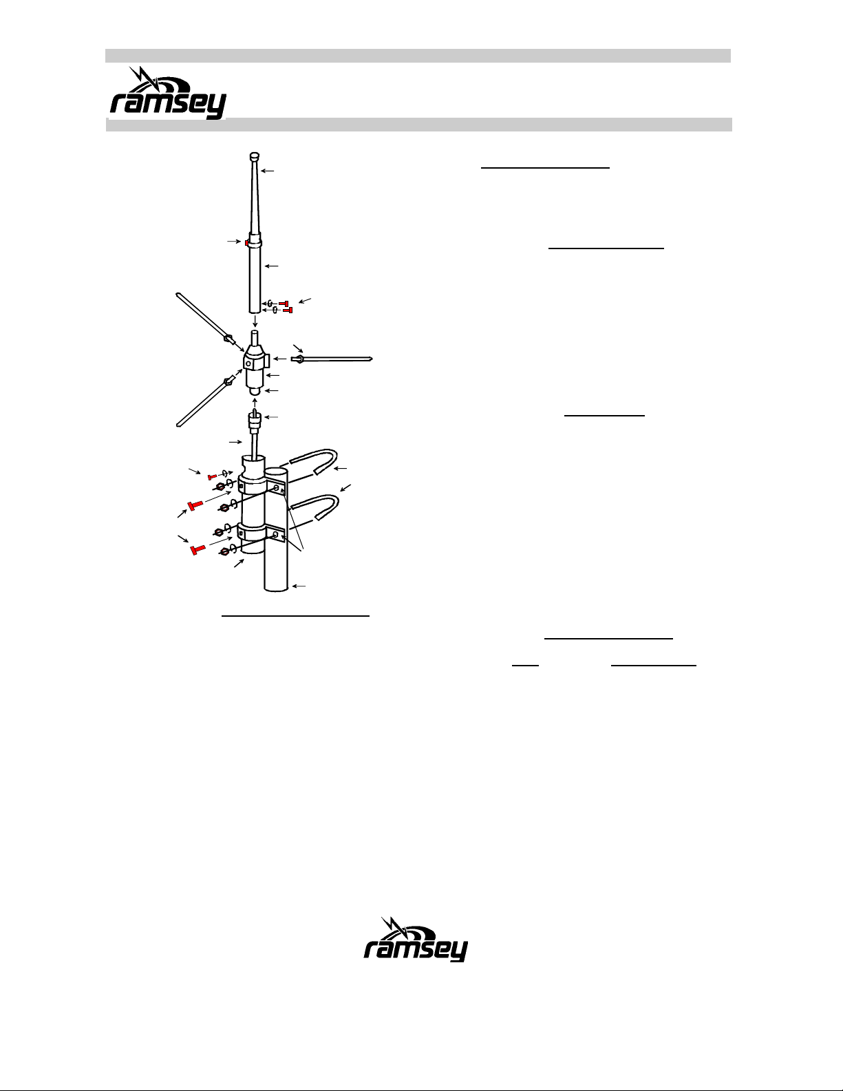
FMA200
5/8 Wave FM Broadcast Antenna
(9) H ose Band
Your Coax
(6) Hex Bolt
& W asher
(5) Hex Bolt
(2) M ounting
Support Pipe
(7) Upper Element
(8) Lo wer Element
(11) S crew
w / Sp. Washer
(10) Radial w/ Nut
(1) Base C oil
M-J Connector
M-P Connector
(4) U-Bolt
W ashe r
& Nut
(3) M ounting
Bracket
Your Mast
“Hose Band” Model
- Hose Band (9) is used to affix the
‘Upper’ and ‘Lower’ antenna elements.
SPECIFICATIONS
• Frequency: 88-110 MHz
• Gain: 3.4dBi
• VSWR: Less than 1.5:1
• Max Power: 200 Watts
• Length: 7’ 7”
• Weight: 2.4 Lbs
• Available Mast: 1” - 2 7/16” OD
PARTS LIST
001 Base coil 1
002 Mount support pipe 1
003 Mount bracket 2
004 U-Bolt with hardware 2
005 Hex bolt 2
006 Hex bolt w/washer 1
007 Upper element 1
008 Lower element 1
009 Hose band 1
010 Radial arm w/nut 3
011 Screw w/spring washer 2
ANTENNA ASSEMBLY
1. First, assemble the Upper Element and the Lower
Element with the hose band. Then attach the element assembly to the Base Coil as shown.
2. Attach the (3) ground plane radials to the Base Coil
as shown. Lock them in place with lock nuts.
3. Assemble and attach the (2) mounting brackets to
the Support Pipe as shown. Run your coax up
through the Support Pipe and attach to the connector at the base of the coil (Standard PL-259 connector).
4. Adjust (Tune) the top element length (tip of the Upper Element to the top of the Lower Element) to
your operating frequency, according the Frequency
Tuning Chart.
5. Finally, mount the assembled antenna on your mast
using the two U-Bolt assemblies provided with the
Mount Brackets
FREQUENCY TUNING
FREQ LENGTH APPROX.
87 MHz 41
88 MHz 39 5/16
89 MHz 37 5/8
90 MHz 36”
91 MHz 34 5/8”
92 MHz 32 11/16”
93 MHz 31 1/2”
94 MHz 30 1/2”
95 MHz 28 1/2”
96 MHz 27 3/4”
97 MHz 26 9/16”
98 MHz 25 3/8”
99 MHz 24 1/16”
100 MHz 23 1/4”
101 MHz 22 7/16”
102 MHz 21 5/8”
103 MHz 20 3/8”
104 MHz 19 5/16”
105 MHz 18 1/8”
106 MHz 17 5/16”
107 MHz 16 1/8”
108 MHz 15 3/16”
109 MHz 14 3/16”
110 MHz 13”
Page 2
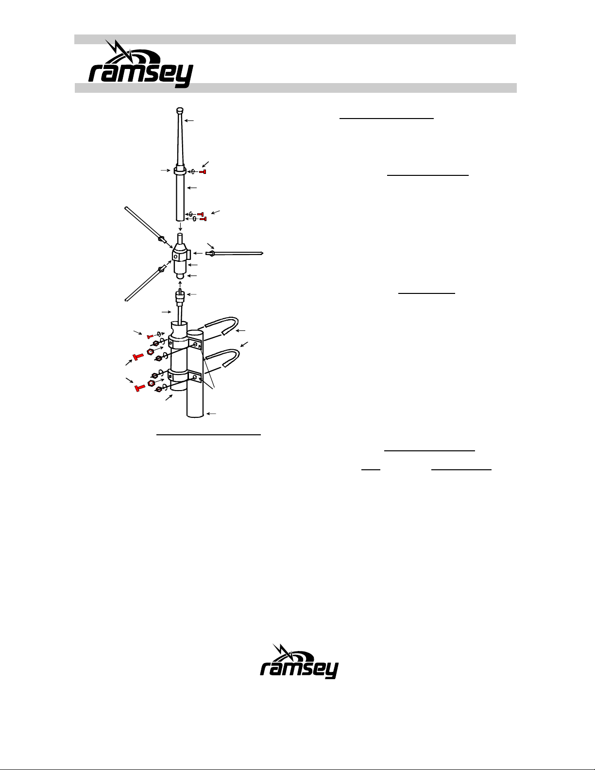
FMA200
5/8 Wave FM Broadcast Antenna
(9) Ring Clamp
Your Coax
(6) H ex Bolt
& Wa sher
(5) Hex Bolt
& N ut
(2) M ounting
Support Pipe
(7) U pper Element
(6) He x Bolt
& Wa sher
(8) Lo wer Element
(11) S crew
w / T. W asher
(10) Radial w/ Nut
(1) Base Coil
M-J Connector
M-P Connector
(4) U -Bolt
W asher
& Nut
(3) M ounting
Bracket
Your Mast
“Ring Clamp” Model
- Ring Clamp (9) is used to affix the
‘Upper’ and ‘Lower’ antenna elements.
SPECIFICATIONS
• Frequency: 88-110 MHz
• Gain: 3.4dBi
• VSWR: Less than 1.5:1
• Max Power: 200 Watts
• Length: 7’ 7”
• Weight: 2.4 Lbs
• Available Mast: 1” - 2 7/16” OD
PARTS LIST
001 Base coil 1
002 Mount support pipe 1
003 Mount bracket 2
004 U-Bolt with hardware 2
005 Hex bolt w/ nut 2
006 Hex bolt w/ washer 2
007 Upper element 1
008 Lower element 1
009 Ring clamp 1
010 Radial arm w/nut 3
011 Screw w/ toothed washer 2
ANTENNA ASSEMBLY
1. First, assemble the Upper Element and the Lower
Element with the ring clamp. Then attach the element assembly to the Base Coil as shown.
2. Attach the (3) ground plane radials to the Base Coil
as shown. Lock them in place with lock nuts.
3. Assemble and attach the (2) mounting brackets to
the Support Pipe as shown. Run your coax up
through the Support Pipe and attach to the connector at the base of the coil (Standard PL-259 connector).
4. Adjust (Tune) the top element length (tip of the Upper Element to the top of the Lower Element) to
your operating frequency, according the Frequency
Tuning Chart.
5. Finally, mount the assembled antenna on your mast
using the two U-Bolt assemblies provided with the
Mount Brackets
FREQUENCY TUNING
FREQ LENGTH APPROX.
90 MHz 41 11/16”
91 MHz 40 5/8”
92 MHz 39 3/8”
93 MHz 38 3/16”
94 MHz 37”
95 MHz 35 13/16”
96 MHz 34 5/8”
97 MHz 33 1/2”
98 MHz 32 5/16”
99 MHz 31 1/2”
100 MHz 29 7/8”
101 MHz 28 11/16”
102 MHz 27 5/8”
103 MHz 26 13/16”
104 MHz 25 5/8”
105 MHz 24 13/16”
106 MHz 23 5/8”
107 MHz 22 13/16”
108 MHz 21 11/16”
109 MHz 20 7/8”
110 MHz 19 11/16”
 Loading...