

Page 1

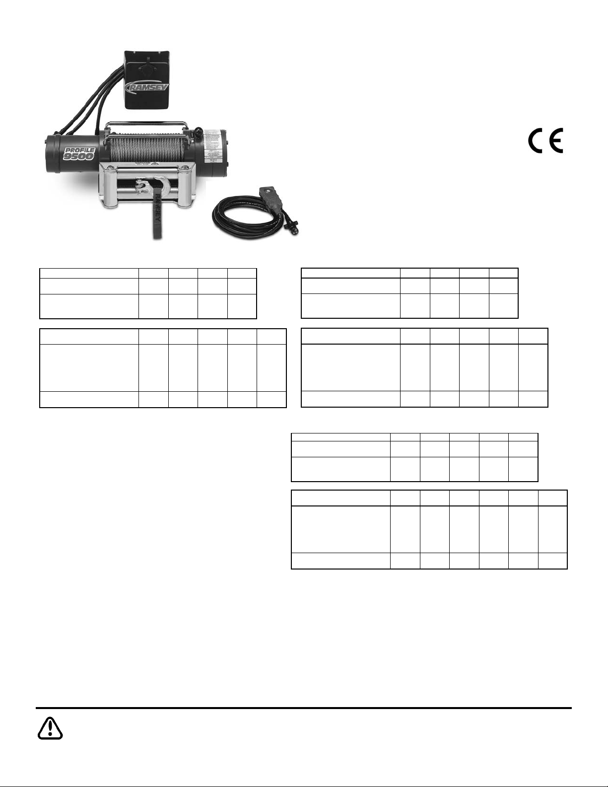
PATRIOT PROFILE 6000
PATRIOT PROFILE 8000
PATRIOT PROFILE 9500
Owner’s Manual
Front Mount Electric Winch
12 & 24 volt
English . . . . . . . . . . . . . . . . . . . . . . . .1
Français . . . . . . . . . . . . . . . . . . . . . .17
Deutsch . . . . . . . . . . . . . . . . . . . . . .33
Español . . . . . . . . . . . . . . . . . . . . . .49
Ramsey Winch Company
P.O. Box 581510 - Tulsa, OK 74158-1510 USA - Phone: (918) 438-2760 - Fax (918) 438-6688
Visit us at http://www.ramsey.com
OM-914117-0309-J
Page 2

Page 3
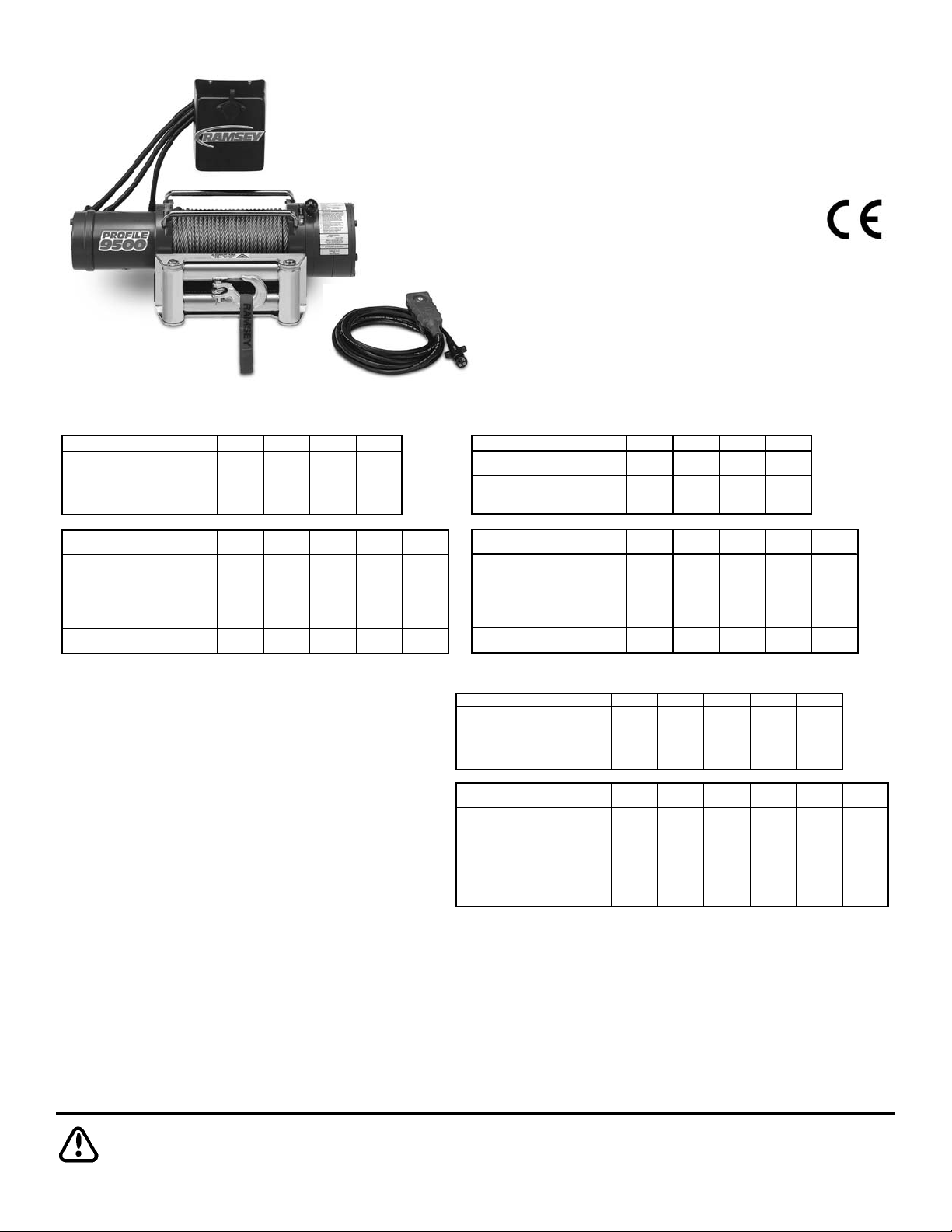
Layer of Cable 1 2 3 4 5
(lbs) 9,500 7,700 6,500 5,700 4,900
(kg) 4,309 3,480 2,940 2,580 2,210
(ft)* 15 35 60 90 105
(m)* 4 10 18 27 32
(lbs) 0 2,000 4,000 6,000 8,000 9,500
(kg) 0 900 1,810 2,720 3,620 4,309
(FPM)
12V
35.4 16.7 12.7 10.6 9 7.8
24V 29 16 13 10 9 8
(MPM)
12V
10.7 5.1 3.8 3. 2 2.7 2.3
24V 8.8 4.9 4.0 3.0 2. 7 2.4
12V 97 180 260 335 395 430
24V 45 95 128 165 192 212
Amp Draw
Rated Line Pull Per Layer
Cumulative Cable
Capacity Per Lay er
(5/16" - 8mm - dia. Cable)
Line Pull First Layer
Line Speed First Lay er
CAUTION: Read and understand this manual before installation and operation of winch. See Safety Precautions!
PATRIOT PROFILE 6000 PATRIOT PROFILE 8000
PATRIOT PROFILE 9500
Layer of Cable 1 2 3 4
(lbs) 6,000 5,000 4,400 3,800
(kg) 2,720 2,260 1,990 1,720
(ft)*205080100
(m)* 6 15 24 30
(lbs) 0 1,000 3,000 5,000 6,000
(kg) 0 450 1,350 2,260 2,720
(FPM)
12V
45 23 20 14 12
24V 46 24 19 15 12
(MPM)
12V
13.7 7 6.1 4.3 3.7
24V 14 7.3 5.8 4.6 3.7
12V 100 200 270 350 405
24V 43 90 128 170 190
Line Speed First Lay er
Amp Draw
Rated Line Pull Per Layer
Cumulative Cable
Capacity Per Lay er
(1/4" - 6mm - dia. Cable)
Line Pull First Layer
Layer of Cable 1 2 3 4
(lbs) 8,000 6,500 5,500 4,800
(kg) 3,620 2,940 2,490 2,170
(ft)*15407095
(m)* 4 12 21 28
(lbs) 0 2,000 4,000 6,000 8,000
(kg) 0 900 1,810 2,720 3,620
(FPM)
12V
35 18 13 10 8
24V 30 17 13 10 8
(MPM)
12V
10.7 5.5 4 3 2.4
24V 9.1 5.2 4 3 2.4
12V 95 210 270 355 420
24V 43 93 125 160 200
Cumulative Cable
Capacity Per Lay er
(5/16" - 8mm - dia. Cable)
Rated Line Pull Per Layer
Line Pull First Layer
Line Speed First Lay er
Amp Draw
You have purchased the finest winch available in its service class. It
features a highly efficient 3 stage planetary gear set which transmits
torque from a series wound DC motor. A safe positive clutch allows
free spooling for quick cable deployment. An automatic load holding
brake is designed to hold the fully rated capacity of the winch. It was
designed and manufactured to provide you with the utmost in utility.
As with any device that combines power and movement in its use,
there are dangers if improperly used. At the same time, there are easier ways for getting the job done if certain precautions are taken first.
Please read this manual carefully. It contains useful ideas in obtaining
Congratulations
the most efficient operation from your Ramsey Winch and safety procedures you
need to know before beginning use. When you follow our guidelines for operation,
your Ramsey Winch will give you many years of satisfying service. Thank you for
choosing Ramsey. You will be glad you have one working for you.
Please note: Ramsey Patriot™ Profile series winches are designed for front
mount vehicle use. The winches are not designed for and should not be
used in industrial applications (car haulers/carriers, wreckers, hoisting,
etc.), and Ramsey does not warrant them to be suitable for such use.
Ramsey makes a separate, complete line of winches for industrial/commercial use. Please contact the factory for further information.
Ramsey Winch Company
Owner’s Manual
Front Mount Electric Winch
12 & 24 V
ENGLISH
* Depends on cable being uniformly wound onto drum
1
Page 4

Table of Contents
Performance Specifications . . . . . . . . . . . . . . . . . . . . . . . . . . . . . . . . . . . . . . . . . . .1
Safety Precautions . . . . . . . . . . . . . . . . . . . . . . . . . . . . . . . . . . . . . . . . . . . . . . . . . .3
Tips for Safe Operation . . . . . . . . . . . . . . . . . . . . . . . . . . . . . . . . . . . . . . . . . . . . . . .3
Techniques of Operation . . . . . . . . . . . . . . . . . . . . . . . . . . . . . . . . . . . . . . . . . . . . . .4
Installation . . . . . . . . . . . . . . . . . . . . . . . . . . . . . . . . . . . . . . . . . . . . . . . . . . . . . . .5-8
Operating Instructions . . . . . . . . . . . . . . . . . . . . . . . . . . . . . . . . . . . . . . . . . . . . . . . .9
Electrical Connections and Operation . . . . . . . . . . . . . . . . . . . . . . . . . . . . . . . . . . . .9
Lubrication/Cable Installation . . . . . . . . . . . . . . . . . . . . . . . . . . . . . . . . . . . . . . . . . .9
Troubleshooting Guide . . . . . . . . . . . . . . . . . . . . . . . . . . . . . . . . . . . . . . . . . . . . . .10
Winch Parts List . . . . . . . . . . . . . . . . . . . . . . . . . . . . . . . . . . . . . . . . . . . . . . . .11-14
Warranty . . . . . . . . . . . . . . . . . . . . . . . . . . . . . . . . . . . . . . . . . . . . . . . . . . . . . . . . .15
2
Page 5

Safety Precautions
To Guard against Possible Injury...
A minimum of five wraps of cable around the drum
barrel is necessary to hold the rated load. Cable
clamp is not designed to hold the load.
A. Keep yourself and others a safe distance to the side of the
cable when pulling under load.
B. Do not step over a cable, or near a cable under load.
C. Use supplied hook strap when handling hook for spooling
wire rope.
D. Do not move the vehicle to pull a load on the winch cable.
This could result in cable breakage and/or winch damage.
E. Use a heavy rag or gloves to protect hands from burrs
when handling winch cable.
F. Apply blocks to wheels when vehicle is on an incline.
G. Winch clutch should be disengaged when winch is not in
use and fully engaged when in use.
H. Modification, alteration, or deviation to the winch should
only be made by Ramsey Winch Company.
I. Keep the duration of your pulls as short as possible. If the
motor becomes uncomfortably hot to the touch, stop and
let it cool for a few minutes. Do not pull more than one
minute at or near rated load. Do not maintain power to the
winch if the motor stalls. Electric winches are for intermit-
tent usage and should not be used in constant duty
applications.
J. Disconnect the remote control switch from the winch
when not in use.
K. NOTE: Do not use winch in hoisting applications due to
required hoist safety factors and features.
L. Do not exceed maximum line pull ratings shown in tables.
Shock loads must not exceed these ratings.
M. To respool correctly, it is necessary to keep a slight load
on the cable. This can be accomplished by (wearing
gloves) holding the cable with one hand and the remote
control switch with the other, starting as far back and in
the center as you can, walking up keeping load on the
cable as the winch is powered in. Do not allow the cable
to slip through your hand and do not approach the winch
too closely. Turn off the winch and repeat the procedure
until all the cable except a few feet is in. Disconnect the
remote control switch and finish spooling in cable by rotating the drum by hand with clutch disengaged. On hidden
winches, spool in cable under power using supplied hook
strap.
Tips for Safe Operation
Don’t underestimate the potential danger in winching operations. Neither should you fear them. Do learn the basic
dangers and avoid them.
Observe the spooling of cable onto drum. Side pulls can
cause cable to pileup at one end of the drum. To correct
uneven stacking, spool out that section of the cable and move
it to the other end of the drum and continue winching. Uneven
spooling which causes cable pileup can interfere with the
solenoid housing causing damage to the winch.
Store the remote control switch inside your vehicle where it
will not become damaged. Inspect it before you plug it in.
When ready to begin spooling in, plug in remote control
switch with clutch disengaged. Do not engage clutch with
motor running.
Never connect the hook back to the cable. This causes cable
damage. Always use a sling or chain of suitable strength, as
shown in the illustration.
Observe your winch while winching, if possible, while standing at a safe distance. If you use vehicle drive to assist, stop
and get out every few feet to assure the cable is not piling up
in one corner. Jamming cable can break your winch.
Do not attach tow hooks to winch mounting apparatus. They
must attach to vehicle frame.
When double lining during stationary winching, the winch
hook should be attached to the chassis of the vehicle.
Since the greatest pulling power is achieved on the innermost
layer of your winch, it is desirable to pull off as much line as
you can for heavy pulls. If this is not practical, use a snatch
block and double the arrangement (see illustration).
Remember, a minimum of 5 wraps of cable around the drum
barrel is necessary to hold the rated load.
Neat, tight spooling avoids cable binding which is caused
when a load is applied and the cable is pinched between two
others. If this happens, alternately power the winch in and out
a few inches. Do not attempt to work a bound cable under
load, free by hand.
3
Page 6
Techniques of Operation
The best way to get acquainted with how your winch
operates is to make a few test runs before you actually
need to use it. Plan your test in advance. Remember
you hear your winch as well as see it operate. Get to
recognize the sound of a light steady pull, a heavy pull,
and sounds caused by load jerking or shifting. Soon you
will gain confidence in operating your winch and its use
will become second nature with you.
Your winch will not only pull your vehicle up or ease your
vehicle down a steep grade, it will also pull another vehicle or a load while your vehicle is anchored in a
stationary position. The sketches on this page show you
a few techniques.
When pulling a heavy load, place a blanket, jacket or tarpaulin over the cable five or six feet from the hook. It
will slow the snap back in the event of a broken cable.
Also, open the vehicle hood for additional protection.
Use the vehicle wheel power to help the winch, but don't
overtake the winch line. Plan your pull. You can't
always hook up and pull out in one step. Examine all the
areas for anchoring possibilities as well as leverage situations, direction, and goal.
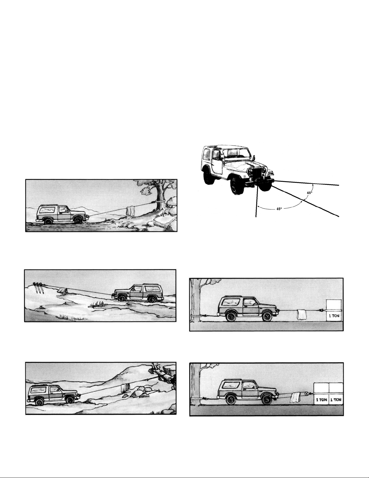
For basic self-recovery, anchor to a tree or heavy rock.
When anchoring to a tree, always use a tree trunk protector.
Stakes driven in solid earth and chained together make a
good anchor point for self-recovery when no solid
anchor point is available.
For a solid anchor, bury a log with earth or sand or place
it in a deep ravine.
Winches equipped with cable guide fairleads can pull
from several directions. Pull from an angle only to
straighten up the vehicle-otherwise you can damage
structural members or other parts of your vehicle and
cause excess cable buildup on one end of the winch
drum.
For a direct pull of 2000 lbs., hitch truck to a tree or
solid anchor, and take out of gear.
To double the pull, use 2-part line and tie off to chassis.
Take out of gear.
4
Page 7
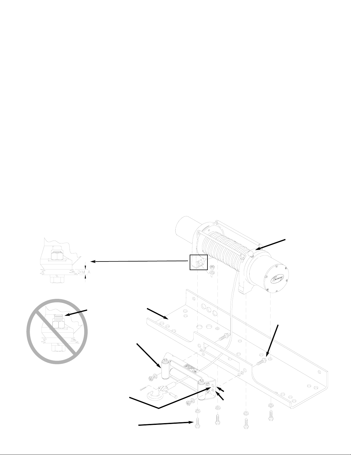
** TO ENSURE PROPER ALIGNMENT
OF FAIRLEAD TO THE DRUM, USE
THE SMALLER DIA. SET OF HOLES
FOR MOUNTING.
WINCH MOUNTING BOLT
3/8-16NC X 1-1/4” LG.
FAIRLEAD MOUNTING
BOLT
3/8-16NC X 1-1/4” LG.
MOUNTING
CHANNEL
ROLLER
FAIRLEAD
1/2” DIA.
7/16” DIA.
*
Installation
The winch shown in this owner’s manual is solely and exclusively designed for vehicle mounted, non-industrial
applications. All other applications will void warranty.
NOTE: For specific bull-bar applications, the shifter lever on
the winch may need to be repositioned. Refer to pages 7-8 for
instructions in how to do this.
It is very important that the winch be mounted on a flat surface so that the three major sections (the motor end, the cable
drum, and the gear housing end) are properly aligned. It is
recommended that Ramsey kits be used to mount the winch.
They are designed to align the winch and distribute up to the
full rated load evenly, to avoid possible damage to the winch
or vehicle.
NOTE: If recommended mounting is not used, a kit of equal
design must be used.
Also available for mounting the Patriot Profile 6000, 8000, and
9500 are the following winch mounting channels:
• #251126 short length (23.63”) black
• #251127 medium length (30.00”) black
• #251128 long length (36.00”) black
It is recommended that Ramsey mounting channels be used
with all non-Ramsey mounting.
For mounting the winch with a standard mounting channel,
such as those available from Ramsey, use (4) 1-1/4” long
mounting bolts as shown below.
* In specific Bull Bar installations, (2) 1-3/4” long bolts
(included) may need to be substituted for 1-1/4” bolts to
mount the winch properly. Refer to Detail A below: if the
mounting thickness (dimension A) is .25” or less, use 11/4” long bolts. If dimension A is greater than .25”, you
should use 1-3/4” long bolts. If dimension A is between
.25” and .56”, washers may need to be added to the 13/4” bolts to prevent the end of the bolt from hitting the
winch foot, as shown in Detail B.
Do not use the longer bolts unless needed. Using bolts
that are too long may cause damage to the winch. After
tightening mounting bolts, confirm that they have sufficient
clearance (see Detail B) above the end of the bolt. Some
thread should be visible above the nut.
** For mounting to Bull Bar, the roller fairlead may need to
be rotated 180° to ensure proper alignment to drum.
CLUTCH SHIFTER
KNOB
DETAIL A
DETAIL B
5
INSUFFICIENT
CLEARANCE
Page 8
6
Attach fairlead to channel using hardware furnished with
winch. Attach winch to channel. Thread capscrews with
lockwashers through mounting holes in channel and into
winch feet (see Figure previous page).
Substitution of attaching hardware items (bolts, nuts or
washers) different from those supplied with your winch
and mounting kit can lead to failure causing damage or
serious injury (use SAE grade 5 bolts or better and
torque to 34 ft.lbs.).
Place end of wire rope through fairlead and attach cable
hook. Use clevis pin and cotter pin.
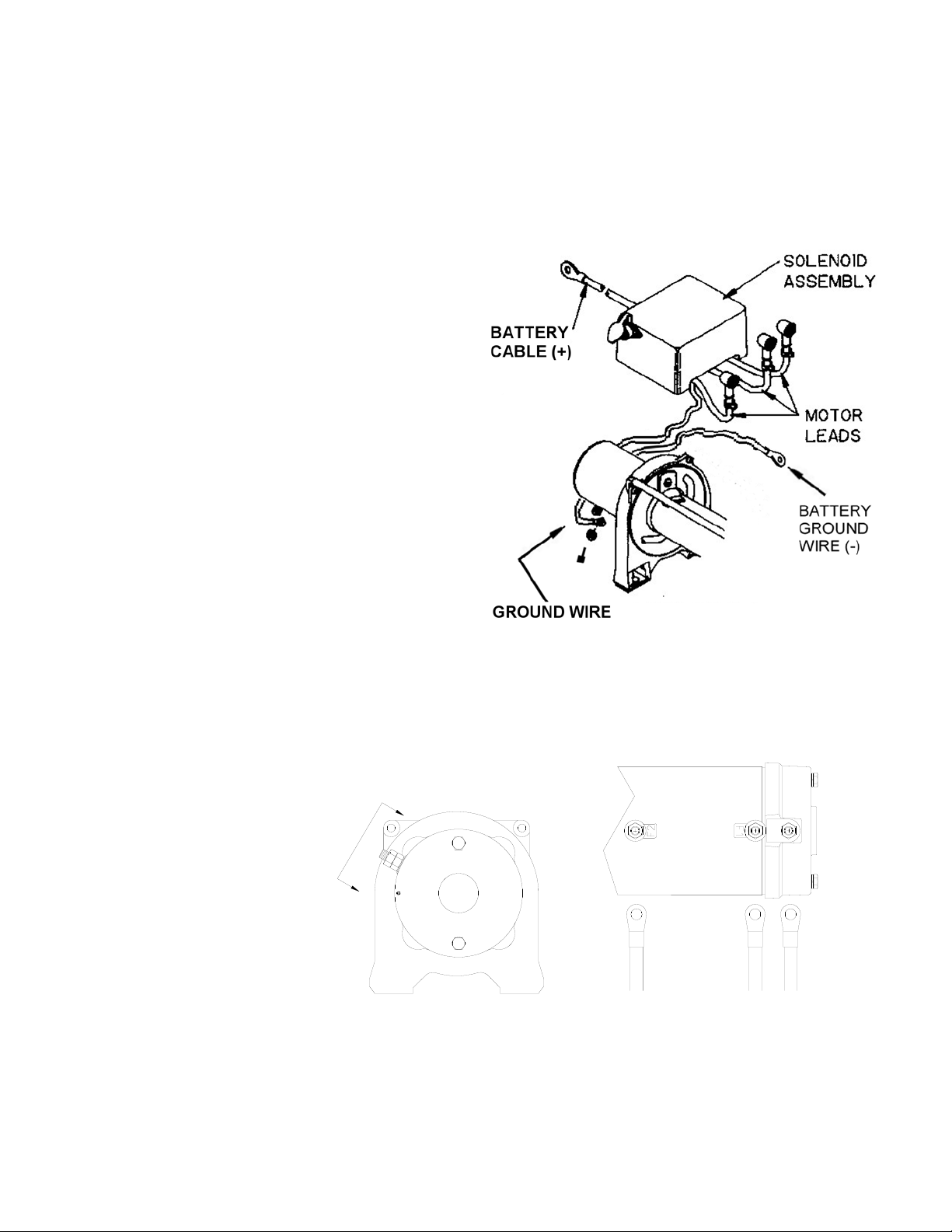
To mount Solenoid Assembly, use included Solenoid
Mounting Bracket. Mount bracket to tie bar using (1)
1/4-20NC x 1” capscrew in place of 3/4” tie bar capscrew. Install bracket to back of solenoid using included
nuts and lockwashers.
When mounting winch, connect labeled motor leads
coming from solenoid assembly to appropriately marked
motor terminals as shown lower right. Tighten nuts on
motor terminals securely. Attach solenoid ground wire
to ground bolt located at bottom of motor (Battery
ground wire is already installed to grounding bolt on
motor).
2
1
A
View A-A
A
A
Page 9
Repositioning Shifter for Specific Bull Bar Applications
Note: The shifter is positioned correctly for most applications. It will only need to be repositioned as necessary for
specific bull bar applications.
Refer to the Parts List and Exploded Parts Diagram for your specific winch elsewhere in this owner’s manual.
1. Position winch as shown in Figure 1. Remove screws from tiebars. You may be able to loosen the screws at the
motor end without removing them. Pull the Gear Housing assembly from the drum and shaft and set it down on
the work bench with the Gear Housing Cover up. Remove the drum bushing from the Gear Housing assembly or
the end of the drum. Set aside.
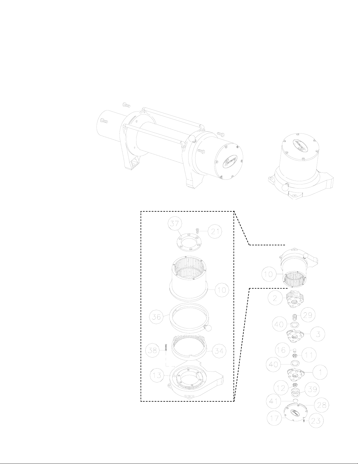
2. Remove (6) capscrews
from the Gear Housing
Cover. Holding the Gear
Housing Cover over the
Gear Housing assem-
bly, flip it over and set it
on the workbench.
3. Gently lift the Gear Housing assembly,
working the gears, bushings, etc. that
are inside the Gear Housing out so that
they are left stacked on the workbench.
See Figure 2.
4. Turn the Gear Housing assembly over
and set on workbench. Remove the
Retainer (item #37) by removing six
capscrews (item #21) from Gear End
Bearing (item 13). Once the retainer is
removed, the Ring Gear (item #10),
Cam Ring (item #36), and Locking Ring
(item #34) can be lifted off the end
bearing.
Remove the six springs (item #38) from
the end bearing.
Figure 2
Figure 3
Figure 1
7
Page 10
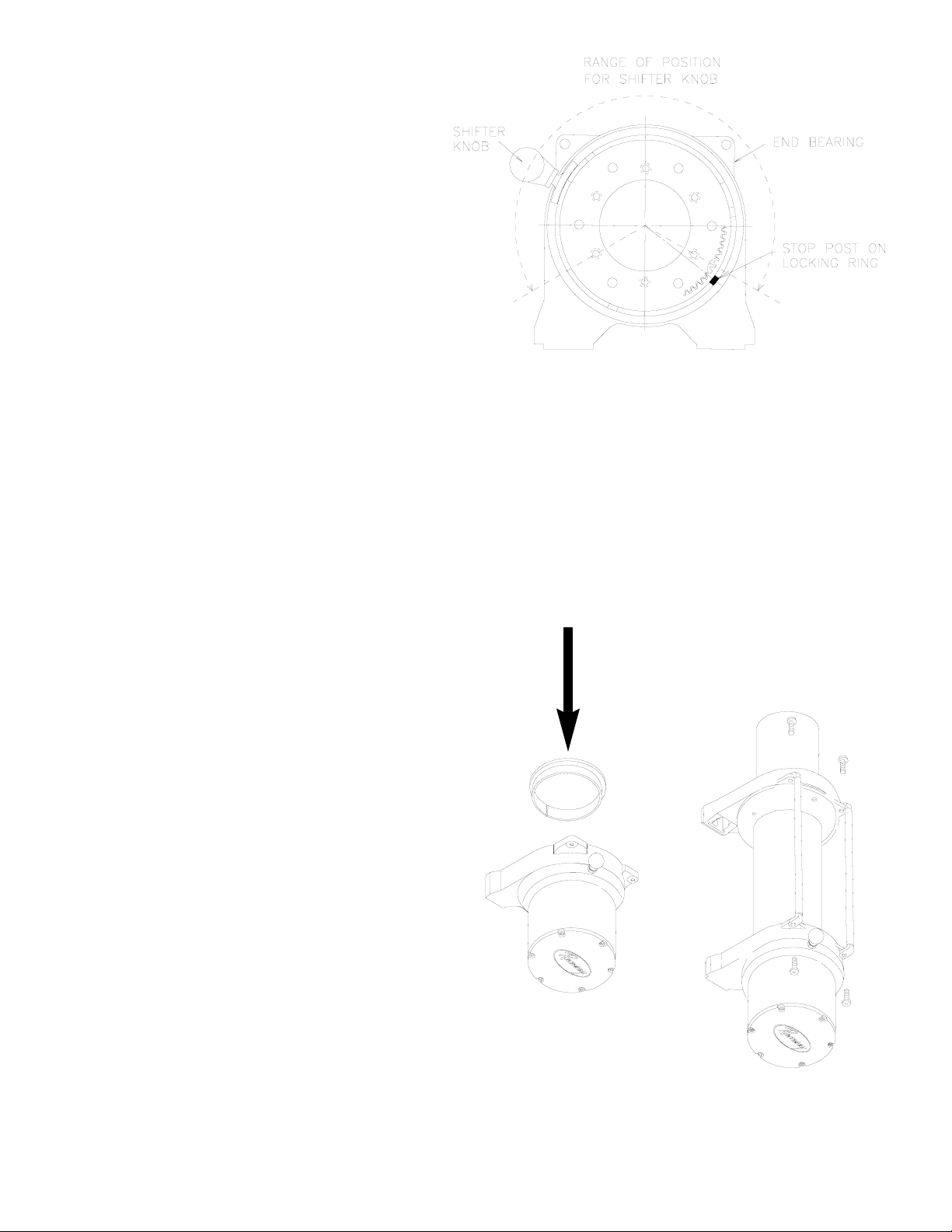
5. Determine position shifter knob needs to be for
your application. Note: Shifter knob cannot be
positioned too low or it will interfere with the feet
on the Gear End Bearing (see Range of Position in
Figure 4).
6. To position the shifter knob, place locking ring in
end bearing with stop post approximately 180°
from where shifter knob needs to be positioned.
Place cam ring over locking ring in proper position and confirm that shifter knob will move from
engaged to disengaged position without interference. Mark position of stop post on end bearing.
7. Remove cam ring and locking ring from end bearing. Insert springs (item #38) into end bearing. When you
replace the locking ring (item #34) over the springs, be sure the springs compress down into their recesses,
and don’t bend sideways.
8. Reassemble Gear Housing as shown in Figure 3. Make sure locking ring is positioned with stop post at marked
location. The capscrews (item #38) for the retainer should be tightened to 40-45 in-lbs. Do not over-tighten.
9. Place Gear Housing over the stacked gears, etc. that you removed in step 3. Gently work the housing over the
stack, turning it as needed to mesh the planetary gears with the ring gear in the housing. Once they are all in the
housing, flip the assembly over. Align the Gear Housing Cover and gasket with the holes in the ring gear. Replace
the (6) capscrews that hold the Gear Housing Cover onto the Gear Housing. Tighten securely.
10. Move the Shifter to the Disengaged position.
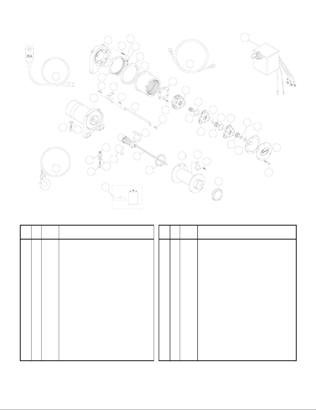
11. Turn the Gear Housing over and set it on the work
bench with the Gear Housing Cover down. See
Figure 5.
12. Install the drum bushing into the Gear Housing, con-
firming that the slot in the bushing is aligned with
the key in the end bearing. Pick up the rest of the
winch (drum and motor end), and holding the drum,
lower the winch onto the gear end. Stab the shaft
into the gear end--you may need to turn the drum
slightly to get the shaft to go all the way in.
13. Place the tiebars on the motor end and gear end and
fasten using (4) screws. Tighten securely.
14. Once the winch is reassembled, turn it so that it is
sitting on its feet. Confirm that the cable will
freespool when the shifter is in the Disengaged position. Connect up the winch temporarily and confirm
that the cable spools when the shifter is in the
Engaged position.
Figure 4
Figure 5
8
Page 11

Operating Instructions
The winch clutch allows rapid unspooling of the wire rope for
hooking onto the load or anchor point. The clutch is operated
by the shifter knob located on the gear housing end of the
winch as follows:
1. To disengage the clutch, move the clutch shifter knob to
the “OUT” position. Wire rope may now be freespooled off
the drum.
2. To engage the clutch, move the clutch shifter knob into the
“IN” position. The winch is now ready for pulling.
Electrical Connections and Operations
See the installation instructions for the Safety On/Off switch,
Part No. 282062 (12V) or 282063 (24v) as applicable, supplied with the winch, to install the On/Off switch.
For normal self-recovery work, your existing electrical system
is adequate. Your battery must be kept in good condition. A
fully charged battery and proper connections are essential.
Run the vehicle engine during winching operations to keep
battery charged.
Route battery cables up to battery.
C
AUTION: BE SURE BATTERY CABLES ARE NOT DRAWN TAUT ACROSS
ANY SURFACES WHICH COULD POSSIBLY DAMAGE THEM
.
Connect red cable to positive (+) battery terminal. Connect
black ground cable to negative (-) terminal of battery (See
Figure 1).
Before operating the winch, turn ON the safety On/Off switch
supplied with the winch.
The remote control switch is water proof. It has push buttons
on either side. Make sure the motor has stopped fully before
reversing. To actuate winch simply plug remote control switch
into receptacle in cover of winch. Run winch forward and
reverse to check directions. Snap appropriate “IN” and “OUT”
disc into proper thumb cavity. Do not leave switch plugged
in when winch is not in use.
Maintenance
All moving parts in the winch are permanently lubricated with
high temperature lithium grease at the time of assembly.
Under normal conditions factory lubrication will suffice.
Lubricate cable periodically using light penetrating oil. Inspect
the cable for broken strands and replace if necessary. If the
cable becomes worn or damaged, it must be replaced.
Corrosion on electrical connections will reduce performance
or may cause a short. Clean all connections especially in the
remote control switch and receptacle. In salty environments
use a silicone sealer to protect from corrosion.
To minimize corrosion of the internal motor components that
may occur due to condensation, power the winch in or out
periodically. Energizing the motor will generate heat, which will
help dissipate any moisture buildup in the motor. This should
be performed at periodic intervals (such as with each oil
change to your vehicle). Note:
Refer to the Troubleshooting
Guide if the motor has been submerged.
Cable Installation
1. Unwind the new cable by rolling it out along the ground to
prevent kinking.
2. Remove old cable and observe the manner in which it is
attached to the cable drum flange.
3. Before installing the new cable assembly, securely wrap
the end of the cable with plastic tape or similar tape to prevent fraying.
4. Position the cable drum so that the large 13/32” diameter
hole in the motor end drum flange is approximately on the
top.
5. Form a short bend (approximately 1/2” long) in the end of
the cable. Insert the bend into the 13/32” hole in the drum
flange and then carefully run the winch in the “reel in”
direction approximately 3/4 revolution until the 1/4” diameter threaded hole in the drum flange is on top.
6. Secure the cable to the drum flange using cable anchor
and capscrew shown in the parts drawing on page 11
(Item nos. 20 and 30). Securely tighten the capscrew, but
do not over-tighten.
7. Wind 5 wraps of cable onto the drum. Wind on the rest of
the cable by pulling in a light load to keep the tension constant. Allow the cable to swivel by using a length of chain
or a swivel block between the cable hook and the load.
9
Page 12

Troubleshooting Guide
10
Condition Possible Cause Correction
Defective or stuck
solenoid
Jar each solenoid to free contacts. Check each solenoid
by applying the appropriate voltage (12 or 24 volts) to coil
terminal (it should make an audible click when energized).
Defective remote control
switch
Disengage winch clutch, remove remote control switch
plug from the socket and jump pins at 8 and 4 o'clock.
Motor should run. Jump pins at 8 and 10 o'clock. Motor
should run.
Long period of operation Cooling off periods are essential to prevent overheating.
Insufficient battery
Check battery terminal voltage (for each battery) under
load. If 10 volts or less, replace or parallel another battery
to it.
Bad connection Check battery cable for corrosion; clean and grease.
Insufficient charging
system
Replace with larger capacity charging system
MOTOR RUNS, BUT
DRUM DOES NOT TURN
Clutch not engaged
If clutch engaged but symptom still exists, it will be
necessary to disassemble winch to determine cause and
repair.
Defective or stuck
solenoid
Jar each solenoid to free contacts. Check each solenoid
by applying the appropriate voltage (12 or 24 volts) to coil
terminal (it should make an audible click when energized).
Defective remote control
switch
Disengage winch clutch, remove remote control switch
plug from the socket and jump pins at 8 and 4 o'clock.
Motor should run. Jump pins at 8 and 10 o'clock. Motor
should run.
Defective motor
If solenoids operate, check for voltage at armature post;
replace motor.
Loose Connections
Tighten connections on bottom side of hood and on
motor.
MOTOR WATER
DAMAGED
Submerged in water or
water from high pressure
car wash
Allow to drain and dry thoroughly, then run motor without
load in short bursts to dry windings.
MOTOR RUNS IN ONLY
ONE DIRECTION
MOTOR RUNS
EXTREMELY HOT
MOTOR RUNS, BUT
WITH INSUFFICIENT
POWER, OR WITH LOW
LINE SPEED.
MOTOR WILL NOT
OPERATE
Page 13
Patriot Profile 6000
11
24
21
5
20
10
26
**19
29
28
37
28
8
16
37
38
21
15
22
9
34
33
12
40
14
26
35
31
43
3
30
16
13
11
34
23
2
12
32
41
18
25
17
1
43
7
39
6
4
Item
No.
Qty. Part No. Description
Item
No.
Qty. Part No. Description
1 1 247006 GEAR CARRIER ASSY - OUTPUT 22 1 414829 CAPSCREW 1/4-20NC X 1" SOC BUTTON HD
2 1 247007 GEAR CARRIER ASSY - INTERMEDIATE 23 1 414830 CAPSCREW 1/4-20NC X 3/8 LG BUTT HD
3
1 247024 GEAR CARRIER ASSY - INPUT 24 6 414861 CAPSCREW 1/4-20NC X 3/4 LG FLAT SOC HD NYLOK
*4 1 251110 SWITCH ASSY 25 6 416273 SCREW #6-32NC X 3/8 LG FIL HD F/B
5 1 251256 CABLE ASSY - 1/4 DIA. X 100' 26 1 418029 NUT 5/16-18NF HX JAM PLTD
6 1 278189 SOLENOID ASSY - 12V 27 4 418035 NUT 3/8-16NC HX REG PLTD
7 1 289141 CABLE ASSY - GROUND 28 5 418177 LOCKWASHER-3/8 ID MED SECT PLTD
8 1 296553 BRAKE/SHAFT ASSY 29 4 418181 WASHER-FLAT 3/8 ID SAE PLTD
9 1 296570 MOTOR-12V 30 1 442207 GASKET-COVER
10 1 282062 ON/OFF SWITCH ASSEMBLY 31 1 444048 GEAR-OUTPUT SUN
11 1 332128 DRUM-CABLE 32 1 444097 GEAR-INPUT SUN
12 1 334143 GEAR-RING 33 2 448049 TIE BAR
13 1 334147 GEAR-INTERMEDIATE SUN 34 1 448071 CABLE ANCHOR
14 1 338337 END BEARING-GEAR HOUSING 35 1 452001 KNOB-SHIFTER
15 1 408315 SOLENOID MOUNTING BRACKET 36 1 477002 LOCKING RING
16 2 412056 BUSHING-DRUM 37 2 477004 RING-HALF
17 1 412061 BUSHING-SHAFT 38 1 477011 CAM RING
18 1 413018 COVER-GEAR HOUSING 39 1 479007 RETAINER-RING GEAR
**19 4 414316 CAPSCREW 3/8-16NC X 1-1/4 LG HX HD GR5 PLTD 40 6 494077 SPRING
2 414317 CAPSCREW 3/8-16NC X 1-3/4 LG HX HD GR5 PLTD 41 2 518019 THRUST WASHER
20 1 414370 CAPSCREW 3/8-24NFX X 1/2 HX HD GR5 Z/P 42 1 518027 THRUST DISC
21 4 414823 CAPSCREW 1/4-20NC X 3/4 LG SOC BUTT HD F/B 43 2 519020 THRUST WASHER
Patriot Profile 6000 Winch Parts List
** See page 5 Installation for determi-
nation of correct bolt.
Page 14
Patriot Profile 8000
12
Item
No.
Qty. Part No. Description
Item
No.
Qty. Part No. Description
1 1 247005 GEAR CARRIER ASSY - INTERMEDIATE 22 1 414829 CAPSCREW 1/4-20NC X 1" SOC BUTTON HD
2 1 247008 GEAR CARRIER ASSY - OUTPUT 23 1 414830 CAPSCREW 1/4-20NC X 3/8 LG BUTT HD
3
1 247024 GEAR CARRIER ASSY - INPUT 24 6 414861 CAPSCREW 1/4-20NC X 3/4 LG FLAT SOC HD NYLOK
4* 1 251110 SWITCH ASSY 25 6 416273 SCREW #6-32NC X 3/8 LG FIL HD F/B
5 1 251255 CABLE ASSY - 5/16 DIA X 95' 26 1 418029 NUT 5/16-18NF HX JAM PLTD
6 1 278189 SOLENOID ASSY - 12V 27 4 418035 NUT 3/8-16NC HX REG PLTD
7 1 289141 CABLE ASSY - GROUND 28 5 418177 LOCKWASHER-3/8 ID MED SECT PLTD
8 1 296553 BRAKE/SHAFT ASSY 29 4 418181 WASHER-FLAT 3/8 ID SAE PLTD
9 1 296570 MOTOR-12V 30 1 442207 GASKET-COVER
10 1 282062 ON/OFF SWITCH ASSEMBLY 31 1 444048 GEAR-OUTPUT SUN
11 1 332128 DRUM-CABLE 32 1 444097 GEAR-INPUT SUN
12 1 334143 GEAR-RING 33 1 448046 CABLE ANCHOR
13 1 334145 GEAR-INTERMEDIATE SUN 34 2 448049 TIE BAR
14 1 338337 END BEARING-GEAR HOUSING 35 1 452001 KNOB-SHIFTER
15 1 408315 SOLENOID MOUNTING BRACKET 36 1 477002 LOCKING RING
16 2 412056 BUSHING-DRUM 37 2 477004 RING-HALF
17 1 412061 BUSHING-SHAFT 38 1 477011 CAM RING
18 1 413018 COVER-GEAR HOUSING 39 1 479007 RETAINER-RING GEAR
19** 4 414316 CAPSCREW 3/8-16NC X 1-1/4 LG HX HD GR5 PLTD 40 6 494077 SPRING
2 414317 CAPSCREW 3/8-16NC X 1-3/4 LG HX HD GR5 PLTD 41 2 518019 THRUST WASHER
20 1 414370 CAPSCREW 3/8-24NFX X 1/2 HX HD GR5 Z/P 42 1 518027 THRUST DISC
21 4 414823 CAPSCREW 1/4-20NC X 3/4 LG SOC BUTT HD F/B 43 2 519020 THRUST WASHER
Patriot Profile 8000 Winch Parts List
24
21
5
20
10
27
**19
29
28
37
28
8
16
37
38
21
15
22
9
36
34
12
40
14
26
35
31
42
3
30
16
13
11
33
23
1
43
32
41
18
25
17
2
42
7
39
6
4
** See page 5 Installation for determina-
tion of correct bolt.
Page 15
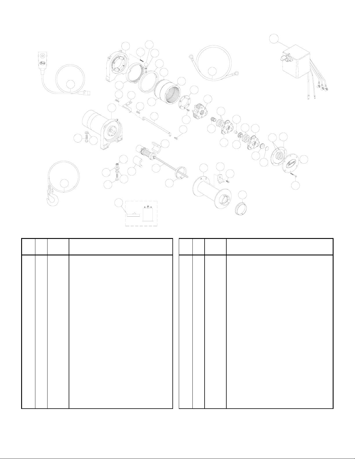
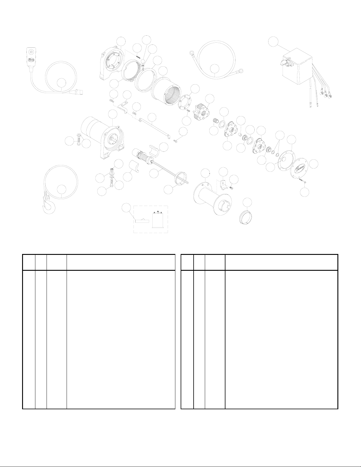
Patriot Profile 9500
13
27
24
5
23
10
29
**22
31
30
39
30
8
19
39
40
24
25
18
9
38
36
33
16
34
42
17
28
37
1
43
15
32
19
13
12]
35
26
2
44
14
43
11
21
20
3
43
7
41
6
4
** See page 5 Installation for determina-
tion of correct bolt.
Item
No.
Qty. Part No. Description
Item
No.
Qty. Part No. Description
1 1 247009 GEAR CARRIER ASSY - INPUT 22** 4 414316 CAPSCREW 3/8-16NC X 1-1/4 HX HD
2 1 247022 GEAR CARRIER ASSY - INTERMEDIATE 2 414317 CAPSCREW 3/8-16NC X 1-3/4 HX HD
3 1 247023 GEAR CARRIER ASSY - OUTPUT 23 1 414370 CAPSCREW 3/8-24NF X 1/2 HX HD
4* 1 251110 SWITCH ASSY 24 4 414823 CAPSCREW 1/4-20NC X 3/4 SOC BT HD
5 1 251257 CABLE ASSY - 5/16 DIA X 105' 25 1 414829 CAPSCREW 1/4-20NC X 1" SOC BUTTON HD
6 1 278189 SOLENOID ASSY - 12V 26 1 414830 CAPSCREW 1/4-20NC X 3/8 BUTTON HD
1 278188 SOLENOID ASSY - 24V 27 6 414861 CAPSCREW 1/4-20NC X 3/4 FL SOC HD NYLOK
7 1 289141 CABLE ASSY - GROUND 28 1 418029 NUT 5/16-18NC HEX JAM PLTD
8 1 296181 BRAKE/SHAFT ASSY 29 4 418035 NUT 3/8-16NC HEX REG PLTD
9 1 296570 MOTOR-12V 30 5 418177 LOCKWASHER-3/8 ID MED SECT PLTD
1 296591 MOTOR-24V 31 4 418181 WASHER-FLAT 3/8 ID SAE PLTD
10 1 282062 ON/OFF SWITCH ASSY - 12V 32 1 442208 GASKET-COVER
1 282063 ON/OFF SWITCH ASSY - 24V 33 1 442219 GASKET-RING GEAR
11 1 328138 COVER-GEAR HOUSING 34 1 444077 GEAR-RING INPUT
12 1 332193 DRUM-CABLE 35 1 448046 CABLE ANCHOR
13 1 334147 GEAR-INTERMEDIATE SUN 36 2 448049 TIE BAR
14 1 334154 GEAR-INPUT SUN 37 1 452001 KNOB SHIFTER
15 1 334197 GEAR-OUTPUT SUN 38 1 477002 LOCKING RING
16 1 334171 GEAR-RING, OUTPUT 39 2 477004 RING-HALF
17 1 338337 END BEARING-GEAR HOUSING 40 1 477011 CAM RING
18 1 408315 SOLENOID MOUNTING BRACKET 41 1 479007 RETAINER-RING GEAR
19 2 412056 BUSHING-DRUM 42 6 494077 SPRING
20 1 412061 BUSHING-SHAFT 43 6 518020 THRUST WASHER
21 6 414159 CAPSCREW 5/16-18NC X 2-1/2 HX HD NYLOK 44 1 518027 THRUST DISC
Patriot Profile 9500 Winch Parts List
Page 16
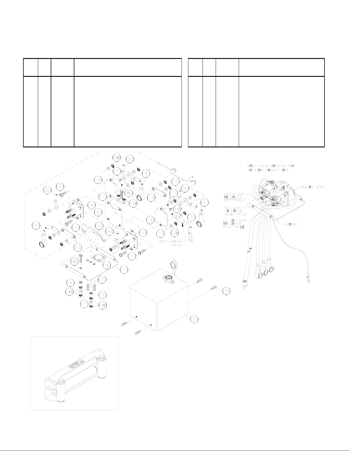
Solenoid Assembly Parts List
278189 12V (Patriot Profile 6000, 8000, 9500)
278188 24V (Patriot Profile 9500)
14
Item
No.
Qty. Part No. Description
Item
No.
Qty. Part No. Description
1 1 204281 ASSEMBLY - SOLENOID BRACKET 9 4 416216 SCREW - #10-24NC X 1/2 LG
2 1 289015 ASSEMBLY - WIRE BATTERY CABLE 72" LG 10 10 418014 NUT - HX 1/4-20NC REG Z/P
3 2 289077 ASSEMBLY - WIRE #6 GA X 4.5" BLACK 11 8 418149 LOCKWASHER - 1/4 MED SECT Z/P
4 3 289170 ASSEMBLY - WIRE #2 GA X 29" MTR LEAD 12 2 418514 SPACER - SOLENOID BRACKET
5 1 296594 COVER ASSEMBLY 13 2 440260 STRAP - COPPER
6 1 408271 BRACKET - SOLENOID MOUNTING 14 4 440262 SOLENOID - 12V
7 6 414042 CAPSCREW 1/4-20NC X 5/8" HX HD 4 440265 SOLENOID - 24V
8 2 414062 CAPSCREW 1/4-20NC X 1-1/2" GR5 Z/P 15 1 440281 ASSEMBLY - WIRE GROUND
16 1 472069 GROMMET
and 9500 winches. Mounting hardware for roller
Roller Fairlead
#251183
fairlead included with winch.
Included with Patriot Profile 6000, 8000,
Page 17

Warranty Information
Ramsey Winches are designed and built to exacting specifications. Care and skill go into every winch we make. If
the need should arise, warranty procedure is outlined on the back of your self-addressed postage paid warranty
card. Please read and fill out the enclosed warranty card and send it to Ramsey Winch Company. If you have problems with your winch, please follow instructions for proper service on all warranty claims.
Limited Lifetime Warranty
Ramsey Winch offers a limited lifetime warranty for each new
Ramsey consumer/RV winch against manufacturing defects in workmanship and materials on all mechanical components.
Warranty registration cards for each winch must be submitted at
the time of purchase or within 30 days. Warranty will only be valid
for the original purchase of the winch and installed on the vehicles
with which they were originally registered.
New cable assemblies are warranted against defects in workmanship and materials. No warranty applies after initial use.
All Ramsey mounting kits and other accessories carry a 1-year limited warranty against defects in material and workmanship.
This warranty is void if winch is used in commercial/industrial applications other than front mount self-recovery.
Electrical components consisting of motors, solenoids, wiring, wire
connectors and associated parts carry a 1-year limited warranty.
Battery isolators carry a 90-day limited warranty.
The obligation under this Warranty, statutory or otherwise, is limited
to the replacement or repair at the manufacturer’s factory, or at a
point designated by the manufacturer, upon inspection of such part,
to have been defective in material or workmanship. This Warranty
does not obligate Ramsey Winch Company to bear the cost of transportation charges in connection with the replacement or repair of
defective parts, nor shall it apply to a product upon which repairs or
alterations have been made, unless authorized by the manufacturer,
or for equipment misused, neglected, or improperly installed.
IMPORTANT NOTICE: To the fullest extent permitted by applicable law, the following are hereby excluded and disclaimed:
1. All warranties of fitness for a particular purpose; 2. All
warranties of merchantability; 3. All claims for consequential
or incidental damages. There are no warranties that extend
beyond the description that appears on the face hereof.
Some states do not allow the above exclusions or disclaimers
in consumer transactions and as such this disclaimer/exclusion may not apply to your particular case.
To the extent such warranties of fitness for a particular purpose or
merchantability are deemed to apply to this product, they exist for
only so long as the express limited warranty elsewhere set forth is
in existence.
Ramsey Winch Company makes no warranty in respect to accessories, same being subject to the warranties of their respective
manufacturers.
Ramsey Winch Company, whose policy is one of continuous product improvement, reserves the right improve any product through
changes in design and materials as it may deem desirable without
being obligated to incorporate such changes in products of previous
manufacture.
If field service at the request of the buyer is rendered and the fault is
found not to be with Ramsey Winch Company’s product, the buyer
shall pay the time and expense cost of the field representative. Bills
for service, labor, or other expenses which have been incurred by
the buyer without express approval or authorization by Ramsey
Winch Company wil not be accepted.
This warranty gives you specific legal rights and you may also have
other legal rights which vary from state to state.
15
Page 18

16
Page 19
Couche(s) de câble 1 2 3 4 5
(lbs) 9,500 7,700 6,500 5,700 4,900
(kg) 4,309 3,480 2,940 2,580 2,210
(ft)* 15 35 60 90 105
(m)* 4 10 18 27 32
(lbs) 0 2,000 4,000 6,000 8,000 9,500
(kg) 0 900 1,810 2,720 3,620 4,309
(FPM)
12V
35.4 16.7 12.7 10.6 9 7.8
24V 29 16 13 10 9 8
(MPM)
12V
10.7 5.1 3.8 3. 2 2.7 2.3
24V 8.8 4.9 4.0 3.0 2. 7 2.4
12V 97 180 260 335 395 430
24V 45 95 128 165 192 212
Courant tiré
Capacité de tract ion
nominale par couche
Capacité de tract ion
cumulative par couche
(5/16" - 8mm - dia.)
Capacité de tract ion,
première couc he
Vitesse de t raction,
première couc he
MISE EN GARDE : on doit lire et comprendre le présent guide avant de procéder à l'installation et à l'utilisation du treuil. Se
reporter à la section Consignes de sécurité.
PATRIOT PROFILE 6000
PATRIOT PROFILE 8000
PATRIOT PROFILE 9500
Couche(s) de câble 1 2 34
(lbs) 6,000 5,000 4,400 3,800
(kg) 2,720 2,260 1,990 1,720
(ft)*205080100
(m)* 6 15 24 30
(lbs) 0 1,000 3,000 5,000 6,000
(kg) 0 450 1,350 2,260 2,720
(FPM)
12V
45 23 20 14 12
24V 46 24 19 15 12
(MPM)
12V
13.7 7 6.1 4.3 3.7
24V 14 7.3 5.8 4.6 3.7
12V 100 200 270 350 405
24V 43 90 128 170 190
Vitesse de traction,
première couc he
Courant tiré
Capacité de tract ion
nominale par couche
Capacité de tract ion
cumulative par couche
(1/4" - 6mm - dia.)
Capacité de tract ion,
première couc he
Couche(s) de câble 1 2 3 4
(lbs) 8,000 6,500 5,500 4,800
(kg) 3,620 2,940 2,490 2,170
(ft)* 15 40 70 95
(m)* 4 12 21 28
(lbs) 0 2,000 4,000 6,000 8,000
(kg) 0 900 1,810 2,720 3,620
(FPM)
12V
35 18 13 10 8
24V 30 17 13 10 8
(MPM)
12V
10.7 5.5 4 3 2.4
24V 9.1 5.2 4 3 2.4
12V 95 210 270 355 420
24V 43 93 125 160 200
Courant tiré
Capacité de tract ion,
première couc he
Vitesse de t raction,
première couc he
Capacité de tract ion
cumulative par couche
(5/16" - 8mm - dia.)
Capacité de tract ion
nominale par couche
Vous venez de vous procurer le meilleur treuil dans sa catégorie! Il présente
un train planétaire à trois étages extrêmement efficace qui transmet son couple
par l'entremise d'un moteur à courant continu (c.c.) à enroulement série. Son
embrayage direct sécuritaire permet le décrabotage, ce qui accélère le
déploiement du câble. Il est en outre équipé d'un frein à correction automatique
de charge conçu pour supporter la pleine capacité nominale du treuil.
Ces treuils ont été dessinés et fabriqués de manière à être le plus utiles possible. Mais comme tous les dispositifs qui allient puissance et mouvement, ils
présentent certains dangers si on ne les utilise pas correctement. En prenant
d'abord toutes les précautions requises, on élimine non seulement ces dangers, mais on facilite et on accélère les tâches à effectuer.
Félicitations!
Veuillez donc prendre la peine de lire le présent guide attentivement; il contient des renseignements utiles pour tirer le meilleur parti de votre treuil Ramsey, de même que des consignes
de sécurité qu'il vous faut savoir avant de l'utiliser pour la première fois. En observant notre
mode d'emploi, vous garantirez que votre treuil vous offre des années de satisfaction. Nous
vous remercions d'avoir choisi Ramsey; nous sommes convaincus que vous ne le regretterez
pas!
Remarque : les treuils Patriot
MC
de Ramsey sont conçus pour être fixés à l'avant d'un
véhicule. Ils ne conviennent pas aux applications commerciales ou industrielles
(remorqueuses, porte-voitures, dépanneuses, opérations de levage, etc.) et Ramsey
n'en garantit pas le fonctionnement dans de telles conditions; la société offre des
gammes complètes et distinctes de treuils réservés à ces usages. Prière de communiquer avec l'usine pour obtenir de plus amples renseignements à ce sujet.
Ramsey Winch Company
GUIDE DE L'UTILISATEUR
Treuils électriques avant
12 et 24 V
FRENCH
* À condition que le câble soit uniformément distribué sur l'enrouleur
17
Page 20

Table des matières
Caractéristiques techniques . . . . . . . . . . . . . . . . . . . . . . . . . . . . . . . . . . . . . . . . . .17
Consignes de sécurité . . . . . . . . . . . . . . . . . . . . . . . . . . . . . . . . . . . . . . . . . . . . . .19
Conseils de sécurité . . . . . . . . . . . . . . . . . . . . . . . . . . . . . . . . . . . . . . . . . . . . . . . .19
Trucs et techniques . . . . . . . . . . . . . . . . . . . . . . . . . . . . . . . . . . . . . . . . . . . . . . . .20
Installation . . . . . . . . . . . . . . . . . . . . . . . . . . . . . . . . . . . . . . . . . . . . . . . . . . . . .21-24
Mode d'emploi . . . . . . . . . . . . . . . . . . . . . . . . . . . . . . . . . . . . . . . . . . . . . . . . . . . .25
Fonctionnement et câblage électrique . . . . . . . . . . . . . . . . . . . . . . . . . . . . . . . . . . .25
Lubrification/Installation du câble . . . . . . . . . . . . . . . . . . . . . . . . . . . . . . . . . . . . . .25
Diagnostic des anomalies . . . . . . . . . . . . . . . . . . . . . . . . . . . . . . . . . . . . . . . . . . . .26
Liste des pièces . . . . . . . . . . . . . . . . . . . . . . . . . . . . . . . . . . . . . . . . . . . . . . . .27-30
Garantie . . . . . . . . . . . . . . . . . . . . . . . . . . . . . . . . . . . . . . . . . . . . . . . . . . . . . . . . .31
18
Page 21

Consignes de sécurité
Le câble doit faire au moins cinq tours sur l'enrouleur
pour pouvoir soutenir la charge nominale du treuil, ce
que le serre-câble est incapable de faire.
A. L'utilisateur ainsi que toute autre personne doivent se tenir à une
distance latérale sécuritaire du câble lorsque celui-ci tire une
charge.
B. On ne doit pas tenter d'enjamber le câble ou de marcher près de
ce dernier quand il tire une charge.
C. On doit se servir de la sangle fournie lorsqu'on manipule le cro-
chet (cable hook) pour enrouler un câble métallique.
D. On ne doit pas déplacer le véhicule pour tirer sur une longue dis-
tance une charge accrochée au câble, ce qui pourrait causer le
bris de ce dernier ou l'endommagement du treuil.
E. On doit avoir recours à des gants ou à un chiffon épais pour se
protéger des barbures quand on manipule le câble.
F. On doit bloquer les roues du véhicule quand celui-ci est sur une
pente.
G. L'embrayage du treuil doit être désaccouplé quand ce dernier
n'est pas utilisé, et complètement accouplé quand il l'est.
H. Les modifications, changements ou déviations apportés à ces
treuils doivent être confiés à la Ramsey Winch Company.
I. On doit réduire au minimum la durée de chaque traction. Si le
moteur devient inconfortablement chaud au toucher, on doit l'arrêter et le laisser refroidir pendant quelques minutes. Les
charges nominales ou presque nominales ne doivent pas être
tirées plus de une minute. Couper l'alimentation du treuil si le
moteur cale. Ces treuils électriques sont conçus pour un usage
intermittent et ne doivent pas être utilisés en applications de
service constant.
J. On doit déconnecter la télécommande du treuil quand celui-ci
n'est pas utilisé.
K. Remarque : on ne doit pas se servir de ces treuils en applica-
tions de levage puisqu'ils ne répondent pas aux exigences de
ces dernières en matière de caractéristiques et de sécurité.
L. On ne doit pas dépasser les capacités de traction nominales
apparaissant aux tableaux du présent guide; les surcharges d'impact doivent rester en dessous des valeurs qui y sont indiquées.
M. Pour réenrouler correctement le câble, il est nécessaire de lui
appliquer une certaine charge. Pour ce faire, on doit tenir le
câble d'une main (gantée) et la télécommande de l'autre, en
commençant le plus loin et le plus au centre possible et en
marchant vers le véhicule en maintenant la tension sur le câble
pendant que le treuil fait son travail. Prendre soin de ne pas
laisser glisser le câble de sa main et ne pas trop s'approcher du
treuil. Arrêter ce dernier et reprendre la procédure jusqu'à ce qu'il
ne reste plus qu'environ un mètre de câble à réenrouler.
Déconnecter la télécommande et terminer la procédure en
faisant tourner l'enrouleur manuellement (embrayage désaccouplé). En présence de treuils cachés, réenrouler le câble
mécaniquement, en utilisant la sangle de crochet fournie.
Conseils de sécurité
Il ne faut jamais sous-estimer les risques potentiels associés à l'utilisation d'un treuil, mais il ne faut pas non plus les craindre outre
mesure. Il s'agit de connaître les dangers principaux et de tout faire
pour les éviter.
Il faut notamment examiner la disposition du câble sur l'enrouleur; si
on tire latéralement, il peut en effet s'accumuler d'un côté. Pour
remédier à ce problème, on doit dérouler la section empilée, la
déplacer vers l'autre extrémité de l'enrouleur, puis procéder au treuillage. Si l'enroulement n'est pas uniforme, le câble accumulé pourrait
nuire au carter du solénoïde, ce qui entraînerait l'endommagement
du treuil.
On recommande de ranger la télécommande à l'intérieur du véhicule
afin de la protéger d'éventuels dommages, et de l'inspecter avec de
la brancher.
Lorsqu'on est prêt à procéder à l'enroulement, on doit débrayer pour
brancher la télécommande; l'embrayage ne doit jamais être accouplé
pendant que le moteur est en marche.
On ne doit jamais amarrer le crochet au câble, ce qui pourrait
endommager ce dernier. Il faut plutôt employer une bretelle ou une
chaîne assez forte, tel qu'illustré.
Dans la mesure du possible, on doit garder l'œil sur le treuil pendant
qu'il fonctionne (tout en se tenant à une distance respectable). Si on
utilise la force motrice du véhicule pour aider à tirer, il faut sortir à
chaque mètre parcouru pour s'assurer que le câble ne s'accumule
pas d'un côté de l'enrouleur. Un blocage de câble peut provoquer le
bris du treuil.
Ne pas fixer de crochet de remorquage aux dispositifs de fixation du
treuil (le crochet doit plutôt être assujetti au châssis du véhicule).
Lorsqu'on utilise deux câbles en situation de treuillage stationnaire,
le crochet devrait également être assujetti au châssis du véhicule.
Étant donné que c'est la couche la plus près de l'enrouleur qui produit la plus grande force de traction, il est préférable de sortir autant
de câble que possible lorsqu'on veux tirer une charge plus lourde.
S'il est impossible de procéder ainsi, on peut utiliser une moufle
mobile et deux câbles (voir illustration). Il importe de se rappeler que
le câble doit faire au moins cinq tours sur l'enrouleur pour pouvoir
tirer sa charge nominale.
En enroulant le câble de manière uniforme et serrée, on évite les
blocages engendrés par les coincements entre deux câbles. Si cela
se produit, il suffit de faire avancer et reculer le treuil de quelques
pouces à la fois. Il ne faut jamais tenter de dégager mécaniquement
un câble bloqué lorsqu'il est chargé; le cas échéant, procéder
manuellement.
19
Page 22

Trucs et techniques
La meilleure façon de connaître le fonctionnement d'un treuil
est de procéder à quelques essais avant d'en avoir réellement
besoin. Ces essais doivent être planifiés à l'avance. Avec le
temps, on arrive à distinguer le son d'une traction légère et
uniforme de celui d'un effort soutenu ou d'une procédure
irrégulière où la charge avance par à-coups ou se déplace
latéralement. On prend ainsi toute l'assurance requise pour
utiliser le treuil presque d'instinct.
Un treuil peut non seulement tirer un véhicule en haut d'une
pente ou l'aider à la descendre, mais aussi permettre d'en
remorquer un autre ou encore une charge si le véhicule est
ancré en position stationnaire. Les scénarios suivants illustrent certaines techniques à adopter.
Lorsqu'on veut tirer une charge importante, il faut mettre une
couverture, un manteau ou une bâche sur le câble sur les
deux premiers mètres à partir du crochet et ce, afin de ralentir
d'éventuels retours si le câble se brise. Il faut également ouvrir
le capot du véhicule pour plus de protection.
On peut se servir d'une force motrice pour assister le treuil,
mais il faut s'assurer que le câble ne passe pas sous le
véhicule. La procédure doit être bien planifiée. On peut
accrocher la charge et la tirer en une seule opération. Pour ce
faire, il faut bien examiner les points d'ancrage possibles, de
même que les situations, les directions et les objectifs de
traction.
Pour tirer un véhicule d'une simple mauvaise posture,
ancrer le câble à un arbre (se servir alors d'un protecteur de tronc) ou à une pierre lourde.
Une série de piquets plantés dans un sol compact et
reliés par une chaîne peut constituer un bon point d'ancrage en cas d'autorétablissement simple, quand le
câble ne peut être fixé à aucun élément naturel.
Pour obtenir un point d'ancrage solide, enterrer partiellement un billot dans de la terre ou du sable, ou le mettre
dans un fossé profond.
Les treuils munis de fils guide-câble peuvent tirer des
charges de plusieurs directions. On ne doit cependant
tirer en angle que pour rétablir le véhicule, au risque
d'endommager les éléments structurels ou d'autres
pièces de ce dernier ou encore d'engendrer une accumulation de câble d'un côté de l'enrouleur.
Pour tirer directement une charge pouvant aller jusqu'à
900 kg, accrocher le véhicule à un point d'ancrage
solide (un arbre, par exemple) et le mettre au neutre.
Pour doubler la force de traction, on peut se servir de
deux câbles, avec une moufle mobile et une attache au
châssis (le véhicule doit être mis au neutre).
20
Page 23

** Pour garantir l’alignement du
guide-câble avec l’enrouleur, se servir
des plus petits trous pour le montage.
Boulon de fixation du treuil
3/8-16NC X 1-1/4” LG.
Boulon de fixation du
guide-câble
3/8-16NC X 1-1/4” LG.
Goulotte
Guide-câble
à rouleaux
Diamètre
de 12,7 mm
Diamètre de
11,1 mm
*
Installation
Les treuils décrits dans le présent guide sont exclusivement conçus
pour une installation à l'avant d'un véhicule et pour des applications
non industrielles ou commerciales. Tout autre emploi en annulerait la
garantie.
Remarque : en présence d'un protège-calandre, la manette d'embrayage (clutch shifter knob) pourrait devoir être déplacée. Se
reporter alors aux pages 7 et 8 pour savoir comment procéder.
Il est très important de fixer le treuil à une surface plane, de manière
à ce que ses trois sections principales (le moteur, l'enrouleur et l'engrenage) soient bien alignées. On recommande d'utiliser une trousse
Ramsey pour procéder à l'installation; ces trousses sont conçues
pour aligner le treuil, en distribuant la charge nominale uniformément, ce qui permet d'éviter d'éventuels dommages au treuil et au
véhicule.
Remarque : si on n'utilise pas la trousse Ramsey, on doit se servir
d'une autre de conception équivalente.
Pour fixer son treuil Patriot Profile 6000, 8000, ou 9500, on peut
également se procurer une des goulottes (mounting channel) suivantes :
• 251126, courte, 60,02 cm, noire
• 251127, moyenne, 76,20 cm, noire
• 251128, longue, 91,44 cm, noire
On recommande d'utiliser une goulotte pour toutes les installations
utilisant des dispositifs autres que ceux de Ramsey.
Pour fixer le treuil dans une goulotte régulière (comme celles
offertes par Ramsey), on doit utiliser quatre boulons de fixation
(winch mounting bolt) de 3 cm, tel qu'illustré ci-dessous.
* En présence d'un protège-calandre, il pourrait être néces-
saire de remplacer les deux boulons de 44,5 mm fournis par des
plus courts (31,8 mm). Se reporter au DÉTAIL A ci-dessous : si
l’épaisseur de la surface de montage (DIM A) est de 6,4 mm ou
moins, il faut employer des boulons de 31,8 mm; si la surface
est plus épaisse, il est préférable de garder les boulons de 44,5
mm. (Si l’épaisseur se situe entre 6,4 et 14,2 mm, on peut
ajouter des rondelles pour empêcher l'extrémité des boulons de
toucher les supports du treuil, tel qu'illustré au DÉTAIL B.)
Il ne faut cependant utiliser des boulons plus longs qu'en
cas de nécessité, puisqu’ils risquent d’endommager le treuil.
Une fois les boulons serrés, s’assurer qu’il y ait suffisamment
d’espace libre (DÉTAIL B) au-dessus de leur extrémité. (Une partie du filetage doit rester visible au-dessus de l’écrou.).
** Lorsqu’on installe le treuil sur un protège-calandre, le
guide-câble à rouleaux pourrait devoir être tourné de 180° pour
en assurer l'alignement avec l'enrouleur.
Manette de
commande
DÉTAIL A
DÉTAIL B
21
Espace
insuffisant
Page 24

22
Fixer le guide-câble à la goulotte au moyen des ferrures
fournies. Installer le treuil dans la goulotte. Insérer des vis de
fixation dotées de rondelles de blocage dans les orifices de
fixation de la goulotte, puis à travers les supports du treuil (se
reporter à la figure de la page précédente).
En remplaçant les ferrures fournies (boulons, écrous ou rondelles) par des accessoires différents, on s'expose à des
risques de défaillance susceptibles d'engendrer des dommages ou des blessures graves (le cas échéant, employer des
éléments homologués SAE n° 5 ou plus, et exercer un couple
de serrage de 34 pi-lb).
Passer l'extrémité du câble métallique à travers le guide-câble
et fixer le crochet, en se servant d'un axe à épaulement et
d'une goupille fendue.
Pour installer le solénoïde (solenoid assembly), on doit se
servir du support de montage fourni. Fixer ce dernier à la
barre d'attache au moyen de une vis 1/4-20NC de 2,5 cm au
lieu de celle de 2,0 cm. Assujettir le support à l'arrière du
solénoïde au moyen des écrous et des rondelles de blocage
fournis.
Lorsqu'on fixe le treuil, il faut raccorder les fils de sortie identifiés (motor leads) du solénoïde aux bornes appropriées du
moteur, tel qu'illustré à droite. Serrer les écrous de ces
bornes fermement. Relier le fil de terre du solénoïde (ground
wire) au boulon de terre situé sur la partie inférieure du
moteur (le fil de terre de l'accumulateur [battery ground wire]
y est déjà raccordé).
A
A
View A-A
A
1
2
Vue A-A
Page 25

Repositionnement de la manette d'embrayage en présence d'un protège-calandre
Remarque : la manette d'embrayage est correctement placée pour la plupart des applications, mais elle pourrait
devoir être déplacée en présence de certains protège-calandre.
Se reporter à la liste des pièces (Parts List) et à la vue éclatée (Exploded Parts Diagram) relatives au modèle de treuil
utilisé, apparaissant ailleurs dans le présent guide.
1. Placer le treuil de la manière illustrée à la figure 1. Retirer les vis des barres d'attache (à l'extrémité moteur, on
peut peut-être simplement les dévisser sans les retirer). Séparer le logement de l'engrenage de l'enrouleur et du
mandrin et le déposer sur l'établi en mettant le couvercle vers le haut. Retirer la bague de l'enrouleur du logement
de l'engrenage ou de
l'extrémité de l'enrouleur; la mettre de
côté.
2. Retirer les six vis de
fixation du couvercle du
logement de l'engrenage. En tenant ce
couvercle au-dessus du
logement, le retourner
et le déposer sur
l'établi.
3. Soulever délicatement le logement de
l'engrenage en manipulant les éléments
internes (roues, bagues, etc.) de
manière à ce qu'ils s'empilent sur l'établi
(figure 2).
4. Retourner le logement de l'engrenage et
le déposer sur l'établi. Retirer le dispositif de retenue (article 37 - retainer) en
enlevant les six vis de fixation (article 21
- capscrews) du palier de l'extrémité
engrenage (article 13 - gear end bearing). Une fois cette étape complétée, la
couronne (article 10 - ring gear), la
couronne à cames (article 36 - cam
ring) et la rondelle de blocage (article 34
- locking ring) peuvent être soulevées du
palier.
Retirer les six ressorts (article 38 springs) du palier.
Figure 2
Figure 3
Figure 1
23
Page 26

5. Déterminer la position dans laquelle la manette
doit être. Remarque: elle ne peut être placée trop
bas puisqu'elle serait ainsi gênée par le support
du palier de l'extrémité engrenage (possibilités de
placement [Range of position] à la figure 4).
6. Pour placer la manette au bon endroit, mettre la
rondelle de blocage du palier d'extrémité (end
bearing) et sa butée (stop post) à un angle d'environ 180° de l'emplacement visé. Poser la
couronne à cames en position au-dessus de la
rondelle de blocage et s'assurer que la manette
puisse se déplacer librement. Marquer la position
de la butée sur le palier d'extrémité.
7. Enlever la couronne à cames et la rondelle de blocage du palier. Insérer les ressorts (article 38) dans ce dernier.
Au moment de remettre la rondelle de blocage (article 34) sur les ressorts, s'assurer que ceux-ci se compriment
bien dans leurs alvéoles, sans plier latéralement.
8. Remonter le logement de l'engrenage tel qu'illustré à la figure 3. S'assurer que la rondelle de blocage soit placée
de manière à ce que la butée arrive à l'endroit marqué. Les vis de fixation (article 21) du dispositif de retenue
devraient être serrées en appliquant un couple de 40 à 45 po-lb. Ne pas trop serrer.
9. Remettre le logement de l'engrenage sur les éléments empilés et retirés à l'étape 3. Manipuler délicatement le
logement en le tournant au besoin pour qu'à l'intérieur, les roues du train planétaire entrent en prise avec la
couronne. Un fois le tout inséré, retourner l'assemblage et aligner le couvercle et le joint d'étanchéité avec les
trous de la couronne. Remettre les six vis de fixation du couvercle pour le fixer au logement. Serrer fermement.
10. Mettre la manette en position de dégagement.
11. Retourner le logement de l'engrenage et le déposer
sur l'établi, en mettant le couvercle vers le bas (figure 5).
12. Installer la bague de l'enrouleur sur le logement, en
confirmant que la fente de la bague s'aligne avec la
clavette du palier d'extrémité. Prendre le reste du
treuil (enrouleur et moteur) et, en tenant l'enrouleur,
abaisser le treuil sur l'extrémité engrenage. Enfoncer
le mandrin dans l'extrémité engrenage; il pourrait
s'avérer nécessaire de tourner légèrement l'enrouleur
pour permettre au mandrin d'entrer jusqu'au bout.
13. Poser les barres d'attache sur les extrémités moteur
et engrenage; fixer le tout au moyen de quatre vis.
Serrer fermement.
14. Une fois le treuil remonté, le retourner et le poser sur
ses supports. Confirmer que le câble puisse
décraboter quand la manette est en position de dégagement. Brancher temporairement le treuil et s'assurer que le
câble s'enroule quand la manette est en position de traction.
Figure 4
Figure 5
24
Page 27

Mode d'emploi
L'embrayage du treuil permet le déroulement rapide d'un câble
métallique pour l'accrocher à une charge ou à un point d'ancrage. La manette d'embrayage est située du côté engrenage
du treuil et fonctionne comme suit :
1. Pour débrayer, mettre la manette à la position de déroulement (OUT); le câble peut alors être facilement décraboté.
2. Pour embrayer, mettre la manette à la position d'enroulement (IN); le treuil est alors prêt à tirer.
Fonctionnement et câblage électrique
Se reporter aux directives d’installation de l’interrupteur de
sécurité (n° 282063, fourni avec le treuil).
Pour les travaux d'autorétablissement normaux, le système
électrique existant suffit. L'accumulateur du véhicule doit
cependant être maintenu en bon état. Il est en effet essentiel
qu'il soit pleinement chargé et que les raccords soient bien
effectués. On doit faire tourner le moteur du véhicule quand on
se sert du treuil afin de conserver la charge de l'accumulateur.
Acheminer les fils d'accumulateur jusqu'à ce dernier.
MISE EN GARDE : S'ASSURER QUE CES FILS NE SOIENT PAS
TENDUS SUR DES SURFACES SUSCEPTIBLES DE LES
ENDOMMAGER.
Raccorder le fil rouge à la cosse positive (« + ») et le fil de
terre noir à la cosse négative (« - »); se reporter à la figure 1.
Étanche, la télécommande est dotée d'un bouton-poussoir de
chaque côté. Il faut toujours s'assurer que le moteur soit complètement arrêté avant de passer en marche avant ou arrière.
Pour activer le treuil, il suffit de brancher la télécommande
dans la prise située sur le logement. Faire avancer et reculer le
câble pour confirmer que les raccords ont été bien effectués
et pour déterminer le sens de chaque bouton. Insérer les rondelles d'enroulement (IN) et de déroulement (OUT) dans les
repose-pouce appropriés. Débrancher la télécommande
quand le treuil n'est pas utilisé.
Maintenance
Toutes les pièces mobiles du treuil ont été lubrifiées en usine
au moyen de graisse au lithium thermorésistante qui devrait,
en conditions normales d'utilisation, tenir le coup pendant
toute la durée utile de l'appareil.
La câble doit cependant être lubrifié périodiquement avec de
l'huile fluide dégrippante. On doit en outre l'inspecter pour y
déceler les brins brisés et le remplacer au besoin par l'article
correspondant de la liste de pièces du treuil utilisé. Si le câble
est usé ou endommagé, il doit être remplacé.
La corrosion sur les raccords électriques peut réduire le rendement du treuil ou causer un court-circuit. On doit donc
nettoyer tous ces raccords, surtout au niveau de la télécom-
mande et de la prise. Pour plus de protection en milieu salin,
on doit en outre utiliser un agent d'étanchéité à base de silicone.
Pour réduire au minimum la corrosion engendrée par la condensation sur les composantes internes du moteur, on
recommande de mettre le treuil en marche périodiquement. En
fonctionnant, le moteur émettra de la chaleur qui aidera à dissiper toute accumulation d'humidité à l'intérieur. On devrait
procéder ainsi par intervalles réguliers, comme à chaque
vidange d'huile du véhicule, par exemple. Remarque : se
reporter à la section Diagnostic des anomalies si le moteur a
été submergé.
Installation du câble
1. Pour empêcher le bouclage, étendre le câble neuf en le
déroulant sur le sol.
2. Retirer le vieux câble et noter comment il est attaché au
rebord de l'enrouleur.
3. Avant d'installer le nouveau câble, s'assurer que son
extrémité soit coupée bien droite et enveloppée de ruban
de plastique ou autre pour l'empêcher de s'effilocher.
4. Placer l'enrouleur de manière à ce que le grand trou
(diamètre d'environ 10 mm) du rebord de l'enrouleur, côté
moteur, soit à peu près sur le dessus.
5. Former un petit coude (long d'un peu plus de 1 cm) au
bout du câble. Insérer ce coude dans ce trou et faire délicatement tourner le treuil dans le sens de l'enroulement
(IN) sur environ 3/4 de tour, jusqu'à ce que le petit trou
fileté (d'environ 5 mm) soit à son tour sur le dessus.
6. Fixer le câble au rebord de l'enrouleur au moyen du dispositif d'ancrage et de la vis de fixation illustrés dans le
dessin des pièces de la page 11 (articles 20 et 30). Visser
fermement, sans trop serrer.
7. Enrouler manuellement le câble cinq fois autour de l'enrouleur. Procéder ensuite mécaniquement à l'enroulement,
en mettant une légère charge au bout du câble pour maintenir une tension constante. S'assurer que le câble puisse
pivoter librement en utilisant une chaîne ou une moufle
entre le crochet et la charge.
25
Page 28

26
Diagnostic des anomalies
État Cause(s) possible(s) Correctif(s)
LE MOTEUR NE
FONCTIONNE QUE DANS
UN SENS
Solénoïde coincé ou
défectueux
Secouer le solénoïde pour dégager les contacts. Vérifier si
la borne de la bobine émet un déclic quand on y applique
une tension de 12 V.
Télécommande défectueuse
Débrayer le treuil, débrancher la télécommande et relier les
broches à 8 et à 4 heures. Le moteur devrait fonctionner.
Relier les broches à 8 et à 10 heures. Le moteur devrait
fonctionner.
LE MOTEUR SURCHAUFFE
BEAUCOUP
Trop long fonctionnement Faire des arrêts essentiels au refroidissement du moteur.
L’accumulateur est faible
Vérifier la tension aux cosses lorsque le treuil tire sa charge
si elle est de 10 V ou moins, remplacer l’accumulateur ou
en brancher un second en parallèle
LE MOTEUR FONCTIONNE,
MAIS À RÉGIME OU À
VITESSE DE TRACTION
TROP FAIBLE
Mauvais raccords
S’assurer de l’absence de corrosion sur les fils de
l’accumulateur; le cas échéant, les nettoyer et les lubrifier.
Système de chargement
insuffisant
Le remplacer par un système plus puissant.
LE MOTEUR FONCTIONNE,
MAIS L’ENROULEUR NE
TOURNE PAS
Le treuil n'est pas embrayé
Si la manette d’embrayage est en position d’enroulement e
les symptômes persistent, il pourrait s’avérer nécessaire d
démonter le treuil pour trouver le problème et le régler.
LE MOTEUR NE
FONCTIONNE PAS
Solénoïde coincé ou
défectueux
Secouer le solénoïde pour dégager les contacts. Vérifier si
la borne de la bobine émet un déclic quand on y applique
une tension de 12 V.
Télécommande défectueuse
Débrayer le treuil, débrancher la télécommande et relier les
broches à 8 et à 4 heures. Le moteur devrait fonctionner.
Relier les broches à 8 et à 10 heures. Le moteur devrait
fonctionner.
Moteur défectueux
Si le solénoïde fonctionne, vérifier la tension à l’arbre
d’induit; remplacer le moteur si elle est inexistante.
Raccords desserrés Serrer les raccords sous le carter et sur le moteur.
Page 29

Patriot Profile 6000
27
24
21
5
20
10
26
**19
29
28
37
28
8
16
37
38
21
15
22
9
34
33
12
40
14
26
35
31
43
3
30
16
13
11
34
23
2
12
32
41
18
25
17
1
43
7
39
6
4
** Se reporter aux directives de la page 5
pour savoir quels boulons utiliser.
N° de
référence
Quantité
N° de
pièce
Description
N° de
référence
Quantité
N° de
pièce
Description
1 1 247006 SUPPORT D’ENGRENAGE – SORTIE 22 1 414829 VIS DE FIXATION 1/4-20NC de 25,4 mm, tête creuse
2 1 247007 SUPPORT D’ENGRENAGE – INTERMÉDIAIRE 23 1 414830 VIS DE FIXATION 1/4-20NC de 9,5 mm, tête ronde
3
1 247024
SUPPORT D’ENGRENAGE – ENTRÉE 24 6 414861
VIS DE FIXATION 1/4-20NC de 19,1 mm, tête creuse plate,
NYLOK
4 1 251110
TÉLÉCOMMANDE 25 6 416273 VIS 6-32NC de 9,5 mm, tête hexagonale creuse, galvanisée
5 1 251256 CÂBLE – 6,4 mm SUR 30,5 m 26 1 418029 ÉCROU 5/16-18NF, hexagonal bas, galvanisé
6 1 278189 SOLÉNOÏDE (12 V) 27 4 418035 ÉCROU 3/8-16NC, hexagonal régulier, galvanisé
7 1 289141 FIL DE TERRE 28 5 418177 RONDELLE DE BLOCAGE 3/8, sect. milieu, galvanisée
8 1 296553 FREIN/MANDRIN 29 4 418181 RONDELLE PLATE 3/8, SAE, galvanisée
9 1 296570 MOTEUR (12 V) 30 1 442207 JOINT – COUVERCLE
10 1 282062 INTERRUPTEUR 31 1 444048 ENGRENAGE – ROUE SOLAIRE DE SORTIE
11 1 332128 ENROULEUR 32 1 444097 ENGRENAGE – ROUE SOLAIRE D’ENTRÉE
12 1 334143 ENGRENAGE – COURONNE 33 2 448049 BARRE D’ANCRAGE
13 1 334147 ENGRENAGE – ROUE SOLAIRE INTERMÉDIAIRE 34 1 448071 ANCRAGE DU CÂBLE
14 1 338337 PALIER D’EXTRÉMITÉ – CÔTÉ ENGRENAGE 35 1 452001 MANETTE DE COMMANDE
15 1 408315 SUPPORT DE SOLÉNOÏDE 36 1 477002 RONDELLE DE BLOCAGE
16 2 412056 BAGUE – ENROULEUR 37 2 477004 MOITIÉ DE BAGUE
17 1 412061 BAGUE – MANDRIN 38 1 477011 ANNEAU DE CAME
18 1 413018 COUVERCLE DU LOGEMENT DE L’ENGRENAGE 39 1 479007 DISPOSITIF DE RETENUE – COURONNE
**19 4 414316
VIS DE FIXATION 3/8-16NC de 31,8 mm, tête hexagonale,
galvanisée, classe 5
40 6 494077
RESSORT
2 414317
VIS DE FIXATION 3/8-16NC de 44,5 mm, tête hexagonale,
galvanisée, classe 5
41 2 518019
RONDELLE DE BUTÉE
20 1 414370
VIS DE FIXATION 3/8-24NF de 12,7 mm, tête hexagonale,
galvanisée, classe 5
42 1 518027
DISQUE DE BUTÉE
21 4 414823
VIS DE FIXATION 1/4-20NC de 19,1 mm, tête creuse, noire 43 2 519020 RONDELLE DE BUTÉE
Liste des pièces du treuil Patriot Profile 6000
Page 30

Patriot Profile 8000
28
N° de
référence
Quantité
N° de
pièce
Description
N° de
référence
Quantité
N° de
pièce
Description
1 1 247005 SUPPORT D’ENGRENAGE – INTERMÉDIAIRE 22 1 414829 VIS DE FIXATION 1/4-20NC de 25,4 mm, tête creuse
2 1 247008 SUPPORT D’ENGRENAGE – SORTIE 23 1 414830 VIS DE FIXATION 1/4-20NC de 9,5 mm, tête ronde
3
1 247024
SUPPORT D’ENGRENAGE – ENTRÉE 24 6 414861
VIS DE FIXATION 1/4-20NC de 19,1 mm, tête creuse plate,
NYLOK
4 1 251110
TÉLÉCOMMANDE 25 6 416273 VIS 6-32NC de 9,5 mm, tête hexagonale creuse, galvanisée
5 1 251255 CÂBLE – 7,9 mm SUR 29,0 m 26 1 418029 ÉCROU 5/16-18NF, hexagonal bas, galvanisé
6 1 278189 SOLÉNOÏDE (12 V) 27 4 418035 ÉCROU 3/8-16NC, hexagonal régulier, galvanisé
7 1 289141 FIL DE TERRE 28 5 418177 RONDELLE DE BLOCAGE 3/8, sect. milieu, galvanisée
8 1 296553 FREIN/MANDRIN 29 4 418181 RONDELLE PLATE 3/8, SAE, galvanisée
9 1 296570 MOTEUR (12 V) 30 1 442207 JOINT – COUVERCLE
10 1 282062 INTERRUPTEUR 31 1 444048 ENGRENAGE – ROUE SOLAIRE DE SORTIE
11 1 332128 ENROULEUR 32 1 444097 ENGRENAGE – ROUE SOLAIRE D’ENTRÉE
12 1 334143 ENGRENAGE – COURONNE 33 1 448046 ANCRAGE DU CÂBLE
13 1 334145 ENGRENAGE – ROUE SOLAIRE INTERMÉDIAIRE 34 2 448049 BARRE D’ANCRAGE
14 1 338337 PALIER D’EXTRÉMITÉ – CÔTÉ ENGRENAGE 35 1 452001 MANETTE DE COMMANDE
15 1 408315 SUPPORT DE SOLÉNOÏDE 36 1 477002 RONDELLE DE BLOCAGE
16 2 412056 BAGUE – ENROULEUR 37 2 477004 MOITIÉ DE BAGUE
17 1 412061 BAGUE – MANDRIN 38 1 477011 ANNEAU DE CAME
18 1 413018 COUVERCLE DU LOGEMENT DE L’ENGRENAGE 39 1 479007 DISPOSITIF DE RETENUE – COURONNE
19** 4 414316
VIS DE FIXATION 3/8-16NC de 31,8 mm, tête hexagonale,
galvanisée, classe 5
40 6 494077
RESSORT
2 414317
VIS DE FIXATION 3/8-16NC de 44,5 mm, tête hexagonale,
galvanisée, classe 5
41 2 518019
RONDELLE DE BUTÉE
20 1 414370
VIS DE FIXATION 3/8-24NF de 12,7 mm, tête hexagonale,
galvanisée, classe 5
42 1 518027
DISQUE DE BUTÉE
21 4 414823
VIS DE FIXATION 1/4-20NC de 19,1 mm, tête creuse, noire 43 2 519020 RONDELLE DE BUTÉE
Liste des pièces du treuil Patriot Profile 8000
24
21
5
20
10
27
**19
29
28
37
28
8
16
37
38
21
15
22
9
36
34
12
40
14
26
35
31
42
3
30
16
13
11
33
23
1
43
32
41
18
25
17
2
42
7
39
6
4
** Se reporter aux directives de la page 5
pour savoir quels boulons utiliser.
Page 31

Patriot Profile 9500
29
27
24
5
23
10
29
**22
31
30
39
30
8
19
39
40
24
25
18
9
38
36
33
16
34
42
17
28
37
1
43
15
32
19
13
12]
35
26
2
44
14
43
11
21
20
3
43
7
41
6
4
** Se reporter aux directives de la page 5
pour savoir quels boulons utiliser.
N° de
référence
Quantité
N° de
pièce
Description
N° de
référence
Quantité
N° de
pièce
Description
1 1 247009
SUPPORT D’ENGRENAGE – ENTRÉE 22** 4 414316
VIS DE FIXATION 3/8-16NC de 31,8 mm, tête hexagonale,
galvanisée, classe 5
2 1 247022
SUPPORT D’ENGRENAGE – INTERMÉDIAIRE 2 414317
VIS DE FIXATION 3/8-16NC de 44,5 mm, tête hexagonale,
galvanisée, classe 5
3 1 247023
SUPPORT D’ENGRENAGE – SORTIE 23 1 414370
VIS DE FIXATION 3/8-24NF de 12,7 mm, tête hexagonale,
galvanisée, classe 5
4 1 251110
TÉLÉCOMMANDE 24 4 414823 VIS DE FIXATION 1/4-20NC de 19,1 mm, tête creuse, noire
5 1 251257 CÂBLE – 7,9 mm SUR 32,0 m 25 1 414829 VIS DE FIXATION 1/4-20NC de 25,4 mm, tête creuse
6 1 278189 SOLÉNOÏDE (12 V) 26 1 414830 VIS DE FIXATION 1/4-20NC de 9,5 mm, tête ronde
1 278188
SOLÉNOÏDE (24 V) 27 6 414861
VIS DE FIXATION 1/4-20NC de 19,1 mm, tête creuse plate,
NYLOK
7 1 289141 FIL DE TERRE 28 1 418029 ÉCROU 5/16-18NC, hexagonal bas, galvanisé
8 1 296181 FREIN/MANDRIN 29 4 418035 ÉCROU 3/8-16NC, hexagonal régulier, galvanisé
9 1 296570 MOTEUR (12 V) 30 5 418177 RONDELLE DE BLOCAGE 3/8, sect. milieu, galvanisée
1 296591 MOTEUR (24 V) 31 4 418181 RONDELLE PLATE 3/8, SAE, galvanisée
10 1 282062 INTERRUPTEUR (12 V) 32 1 442208 JOINT – COUVERCLE
1 282063 INTERRUPTEUR (24 V) 33 1 442219 JOINT – COURONNE
11 1 328138 COUVERCLE DU LOGEMENT DE L’ENGRENAGE 34 1 444077 ENGRENAGE – COURONNE D’ENTRÉE
12 1 332193 ENROULEUR 35 1 448046 ANCRAGE DU CÂBLE
13 1 334147 ENGRENAGE – ROUE SOLAIRE INTERMÉDIAIRE 36 2 448049 BARRE D’ANCRAGE
14 1 334154 ENGRENAGE – ROUE SOLAIRE D’ENTRÉE 37 1 452001 MANETTE DE COMMANDE
15 1 334197 ENGRENAGE – ROUE SOLAIRE DE SORTIE 38 1 477002 RONDELLE DE BLOCAGE
16 1 334171 ENGRENAGE – COURONNE DE SORTIE 39 2 477004 MOITIÉ DE BAGUE
17 1 338337 PALIER D’EXTRÉMITÉ – CÔTÉ ENGRENAGE 40 1 477011 ANNEAU DE CAME
18 1 408315 SUPPORT DE SOLÉNOÏDE 41 1 479007 DISPOSITIF DE RETENUE – COURONNE
19 2 412056 BAGUE – ENROULEUR 42 6 494077 RESSORT
20 1 412061 BAGUE – MANDRIN 43 6 518020 RONDELLE DE BUTÉE
21 6 414159
VIS DE FIXATION 5/16-18NC de 63,5 mm, tête hexagonale,
NYLOK
44 1 518027
DISQUE DE BUTÉE
Liste des pièces du treuil Patriot Profile 9500
Page 32

Liste des pièces du solénoïde
278189 12V (Patriot Profile 6000, 8000, 9500)
278188 24V (Patriot Profile 9500)
30
N° de
référence
Quantité
N° de
pièce
Description
N° de
référence
Quantité
N° de
pièce
Description
1
1 204281
ASSEMBLAGE – SUPPORT DE SOLÉNOÏDE 9 4 416216 VIS 10-24NC de 12,7 mm
2 1 289015
ASSEMBLAGE – FIL D’ACCUMULATEUR (1,8 m) 10 10 418014 ÉCROU 1/4-20NC, hexagonal régulier, galvanisé
3 2 289077
ASSEMBLAGE – FIL DE CALIBRE 6, NOIR (114,3
mm)
11 8 418149
RONDELLE DE BLOCAGE 1/4, sect. milieu,
galvanisée
4 3 289170
ASSEMBLAGE – FIL DE MOTEUR, CALIBRE 2
(736,6 mm)
12 2 418514
ESPACEUR – SUPPORT DE SOLÉNOÏDE
5 1 296594
CARTER 13 2 440260 BRIDE – CUIVRE
6 1 408271
SUPPORT DE SOLÉNOÏDE 14 4 440262 SOLÉNOÏDE (12 V)
7 6 414042
VIS DE FIXATION 1/4-20NC de 15,9 mm, tête
hexagonale
4 440265
SOLÉNOÏDE (24 V)
8 2 414062
VIS DE FIXATION 1/4-20NC de 38,1 mm,
galvanisée, classe 5
15 1 440281
ASSEMBLAGE – FIL DE TERRE
16 1 472069
PASSE-FIL
REMARQUE : VUE TOURNÉE À 180°
POUR MONTRER LES CONNEXIONS
FIL VERT VERS
LA PRISE DU
CARTER
FIL ROUGE
VERS LA PRISE
DU CARTER
FIL JAUNE VERS
LA PRISE DU
CARTER
TUBE THERMORÉTRÉCISSABLE
Fourni avec les treuils Patriot Profile 6000,
8000 et 9500 (ferrures comprises).
GUIDE-CÂBLE À ROULEAUX
#251183
Page 33

Renseignements sur la garantie
Les treuils Ramsey sont conçus et construits suivant des exigences rigoureuses. Nous mettons un soin particulier et toutes
nos compétences au service de chaque dispositif que nous fabriquons. En cas de besoin, toutes les procédures de réclamations en vertu de la garantie sont indiquées au verso de la fiche pré-adressée port payé que nous vous demandons de bien
vouloir lire, remplir et nous envoyer à la Ramsey Winch Company. Si votre treuil vous cause quelque problème que ce soit,
veuillez suivre nos instructions pour vous assurer un service rapide.
Garantie à vie limitée
La Ramsey Winch Company (ci-après nommée «Ramsey») offre à tout
nouveau consommateur/treuil de véhicules tout-terrain Ramsey une garantie
à vie limitée contre les défauts de fabrication ou de matériaux de tous les
composants mécaniques.
Pour chaque treuil, la fiche d'enregistrement de la dite garantie doit être
envoyée au moment de l'achat ou dans un délai de 30 jours suivant ce
dernier. Elle ne s'applique qu'à l'acheteur initial du treuil, à condition que ce
dernier soit toujours installé sur le véhicule pour lequel il a été enregistré.
Les câbles neufs sont également garantis contre les défauts de fabrication
ou de matériaux jusqu'à ce qu'ils soient utilisés pour la première fois.
Les trousses d'installation et autres accessoires sont appuyés par une
garantie limitée de un an contre les défauts de fabrication ou de matériaux.
Les finis chromés sont garantis pour un an contre les défauts de fabrication;
les fissures, les égratignures ou la corrosion résultat d'opérations de treuillage ne sont cependant pas couverts.
La présente garantie sera nulle et non avenue si le treuil est utilisé dans des
applications commerciales ou industrielles autres que celles d'autorétablissement en installations à l'avant d'un véhicule.
Les composantes électriques (moteurs, solénoïdes, câblage, connecteurs,
etc.) sont assortis d'une garantie limitée de un an, sauf les chargeurs, qui
sont pour leur part garantis pour une période de 90 jours.
Il est à noter qu'il est possible contre paiement de prolonger à deux ans la
garantie limitée offerte sur les composantes électriques.
La seule obligation, statutaire ou autre, de Ramsey en vertu de la présente
garantie sera de réparer ou de remplacer à son usine ou à un emplacement
désigné par elle, les pièces qu'elle jugera , après inspection, défectueuses
au niveau de la fabrication ou des matériaux. La présente garantie n'oblige
pas Ramsey à assumer les frais de transport ou de main-d'œuvre liés au
remplacement ou à la réparation des pièces défectueuses et ne s'applique ni
aux produits réparés ou modifiés par autrui sans l'autorisation de la société,
ni aux produits utilisés à mauvais escient, négligés ou mal installés.
AVIS IMPORTANT : jusqu'aux limites permises par les lois applicables, Ramsey décline toute responsabilité à l'égard de 1. toute
garantie de conformité au besoin; 2. toute garantie de qualité
marchande; 3. toute réclamation attribuable aux dommages indirects
ou consécutifs. Aucune garantie n'est faite au-delà des descriptions
apparentes à la lecture des présentes.
Certains états ou provinces ne permettant ni les exclusions ni les
avis de non-responsabilité, ceux apparaissant ci-dessus pourraient
ne pas s'appliquer à l'acheteur.
Advenant qu'une garantie de conformité au besoin ou de qualité marchande
soit jugée applicable pour le produit visé, elle ne restera en vigueur qu'aussi
longtemps que la garantie limitée expresse stipulée aux présentes.
Ramsey décline toute responsabilité à l'égard des accessoires, ceux-ci étant
couverts par leurs fabricants respectifs.
Ramsey, dont la politique est d'améliorer constamment ses produits, se
réserve le droit de modifier la conception ou les matériaux de ces derniers à
sa discrétion et ce, sans être dans l'obligation d'apporter les mêmes modifications aux produits existants.
Si l'acheteur a recours à des services sur le terrain, et que le défaut ne peut
être attribué à Ramsey, les frais associés devront être déboursés par l'acheteur. Dans le même ordre d'idées, les frais de service, de main-d'œuvre
ou autres engagés par l'acheteur sans l'approbation ou l'autorisation
expresses de Ramsey ne seront pas acceptés par cette dernière.
Si la présente garantie confère à l'acheteur certains droits, d'autres peuvent
lui être accordés en vertu de lois variant d'une province ou d'un état à
l'autre.
31
Page 34

32
Page 35

Seillage 1 2 3 4 5
(lbs) 9,500 7,700 6,500 5,700 4,900
(kg) 4,309 3,480 2,940 2,580 2,210
(ft)* 15 35 60 90 105
(m)*4 10182732
(lbs) 0 2,000 4,000 6,000 8,000 9,500
(kg) 0 900 1,810 2,720 3,620 4,309
(FPM)
12V
35.4 16.7 12.7 10.6 9 7.8
24V 29 16 13 10 9 8
(MPM)
12V
10.7 5.1 3.8 3. 2 2.7 2.3
24V 8.8 4.9 4.0 3.0 2. 7 2.4
12V 97 180 260 335 395 430
24V 45 95 128 165 192 212
Stromaufnahme
Nennzuglast je Lage
Summierte Seilaufnahme
je Lage
(5/16" - 8mm - dia.)
Zuglast, 1. Lage
Seilges chwindigkeit , 1.
Lage
VORSICHT: Lesen Sie sich dieses Handbuch vor der Installation und Inbetriebnahme der Seilwinde sorgfältig durch.
Siehe Sicherheitsvorkehrungen!
PATRIOT PROFILE 6000 PATRIOT PROFILE 8000
PATRIOT PROFILE 9500
Seillage 1 2 3 4
(lbs) 6,000 5,000 4,400 3,800
(kg) 2,720 2,260 1,990 1,720
(ft)*205080100
(m)* 6 15 24 30
(lbs) 0 1,000 3,000 5,000 6,000
(kg) 0 450 1,350 2,260 2,720
(FPM)
12V
45 23 20 14 12
24V 46 24 19 15 12
(MPM)
12V
13.7 7 6.1 4.3 3.7
24V 14 7.3 5.8 4.6 3.7
12V 100 200 270 350 405
24V 43 90 128 170 190
Seilges chwindigkeit , 1.
Lage
Stromaufnahme
Nennzuglast je Lage
Summierte Seilaufnahme
je Lage
(1/4" - 6mm - dia.)
Zuglast, 1. Lage
Seillage 1 2 3 4
(lbs) 8,000 6,500 5,500 4,800
(kg) 3,620 2,940 2,490 2,170
(ft)*15407095
(m)* 4 12 21 28
(lbs) 0 2,000 4,000 6,000 8,000
(kg) 0 900 1,810 2,720 3,620
(FPM)
12V
35 18 13 10 8
24V 30 17 13 10 8
(MPM)
12V
10.7 5.5 4 3 2.4
24V 9.1 5.2 4 3 2.4
12V 95 210 270 355 420
24V 43 93 125 160 200
Summierte Seilaufnahme
je Lage
(5/16" - 8mm - dia.)
Nennzuglast je Lage
Zuglast, 1. Lage
Seilges chwindigkeit , 1.
Lage
Stromaufnahme
Sie haben die technisch ausgereifteste Seilwinde in ihrer Service-Klasse erworben. Sie bietet Ihnen ein hocheffizientes 3-stufiges Planetengetrieb, welches
das Drehmoment von einem Dauermagnet-Gleichstrommotor überträgt. Eine
sichere Klauenkupplung ermöglicht ein ungehindertes Abspulen für einen
schnellen Arbeitseinsatz des Seils. Eine automatische Lastbremse wurde zur
Aufnahme der maximalen Nennleistung der Seilwinde konstruiert.
Bei der Konstruktion und der Herstellung dieser Seilwinde lag das
Hauptaugenmerk auf optimaler Nutzleistung. Wie bei jeglichen anderen
Geräten, bei deren Verwendung Kraft mit Bewegung einhergeht, können bei
unsachgemäßem Gebrauch Gefahren auftreten. Gleichzeitig lässt sich die
Arbeit leichter und schneller erledigen, wenn zuerst gewisse
Vorsichtsmaßnahmen beachtet werden.
Herzlichen Glückwunsch
Lesen Sie sich dieses Handbuch bitte sorgfältig durch. Es enthält nützliche Ideen, wie Sie
Ihre Seilwinde der Marke Ramsey am effizientesten verwenden und welche
Sicherheitsvorkehrungen Sie vor ihrer Inbetriebnahme im Auge behalten sollten. Sofern Sie
unsere Betriebshinweise für Ihre Seilwinde von Ramsey befolgen, werden Sie sicher jahrelang
damit zufrieden sein. Wir danken Ihnen dafür, dass Sie Ramsey gewählt haben. Sie werden
unser Produkt schätzen.
Nehmen Sie bitte folgendes zur Kenntnis: Die Seilwinden der Serie Ramsey PatriotJwurden
ausschließlich zur Befestigung und Verwendung am Vorderteil Ihres Fahrzeugs konstruiert. Die
Seilwinden sind nicht für industrielle Anwendungen vorgesehen (Autoabschleppfahrzeuge/träger, Schachtförderer, u.s.w.) und Ramseys Garantie erstreckt sich auch nicht auf die Eignung
der Seilwinden für derartige Anwendungen. Ramsey stellt für industrielle/gewerbliche Zwecke
ein vollkommen separates Seilwinden-Sortiment her. Erfragen Sie bitte weitere Auskünfte von
der Fabrik.
Ramsey Winch Company
Betriebshandbuch
Elektrowinde für Frontmontage
12 V und 24 V
GERMAN
* Bei gleichmäßig auf die Trommel gewickeltem Seil.
33
Page 36

Inhaltsverzeichnis
Leistungsspezifikationen . . . . . . . . . . . . . . . . . . . . . . . . . . . . . . . . . . . . . . . . . . . . .33
Sicherheitsvorkehrungen . . . . . . . . . . . . . . . . . . . . . . . . . . . . . . . . . . . . . . . . . . . . .35
Tips für den sicherheitsbewussten Gebrauch . . . . . . . . . . . . . . . . . . . . . . . . . . . . .35
Betriebsmethoden . . . . . . . . . . . . . . . . . . . . . . . . . . . . . . . . . . . . . . . . . . . . . . . . . .36
Installation . . . . . . . . . . . . . . . . . . . . . . . . . . . . . . . . . . . . . . . . . . . . . . . . . . . . .37-40
Bedienungsanweisungen . . . . . . . . . . . . . . . . . . . . . . . . . . . . . . . . . . . . . . . . . . . . .41
Elektrische Anschlüsse & Betrieb . . . . . . . . . . . . . . . . . . . . . . . . . . . . . . . . . . . . . .41
Schmierung/Anbringung des Seils . . . . . . . . . . . . . . . . . . . . . . . . . . . . . . . . . . . . .41
Fehlerbehebung . . . . . . . . . . . . . . . . . . . . . . . . . . . . . . . . . . . . . . . . . . . . . . . . . . .42
Ersatzteilliste für Seilwinden . . . . . . . . . . . . . . . . . . . . . . . . . . . . . . . . . . . . . . . .43-46
Garantie . . . . . . . . . . . . . . . . . . . . . . . . . . . . . . . . . . . . . . . . . . . . . . . . . . . . . . . . .47
34
Page 37

Sicherheitsvorkehrungen zum Schutz
gegen potenzielle Verletzungen ...
Um die Nennlast halten zu können, muss das Seil
mindestens fünf Mal um die Trommel gewickelt
sein. Die Seilklemme wurde nicht zum Halten der
Last konstruiert.
A. Halten Sie und andere Personen, wenn das Seil unter Last steht, einen
seitlichen Sicherheitsabstand zu dem Seil ein.
B. Nicht über bzw. in die Nähe des Seils treten, wenn es unter Last steht.
C. Verwenden Sie den mitgelieferten Hakenriemen, wenn Sie mit dem
Haken zum Auf- und Abspulen des Seils zu tun haben.
D. Setzen Sie nicht das Fahrzeug in Bewegung, um mit dem Seil der
Seilwinde eine Last zu ziehen. Dies könnte ein Zerreißen des Seils bzw.
eine Beschädigung der Seilwinde zur Folge haben.
E. Verwenden Sie zum Schutz Ihrer Hände vor Verbrennungen ein dickes
Tuch oder Handschuhe, wenn Sie mit dem Seil zu tun haben.
F. Blockieren Sie die Räder, wenn Ihr Fahrzeug bergauf steht.
G. Die Seilwindenkupplung sollte gelöst werden, wenn die Seilwinde nicht
im Gebrauch ist und bei ihrer Verwendung angezogen werden.
H. Jegliche Veränderungen, Modifikationen, oder Abwandlungen sollten
ausschließlich von der Firma Ramsey Winch vorgenommen werden.
I. Halten Sie den Zeitraum, in dem Sie Lasten ziehen so kurz wie möglich.
Falls der Motor so heiß läuft, dass er nicht anzufassen ist, pausieren Sie
und lassen Sie ihn ein paar Minuten lang abkühlen. Wenn Ihre Last
beinahe die Nennlast beträgt, ziehen Sie bitte nicht über eine Minute lang.
Halten Sie die Stromzufuhr zu der Seilwinde nicht aufrecht, falls der
Motor abstirbt. Elektrische Seilwinden sind zur zwischenzeitlichen
Verwendung gedacht und sollten nicht andauernd betrieben werden.
J. Trennen Sie den Fernbedienungsschalter von der Seilwinde, wenn diese
nicht im Betrieb steht.
K. Anmerkung: Auf Grund der erforderlichen Sicherheitsfaktoren und
Merkmale, bitte die Seilwinde nicht für Hubzwecke verwenden.
L. Übersteigen Sie bitte nicht die in den Tabellen aufgezeigten Zuglast-
Nennleistungen. Auch Stoßbelastungen dürfen diese Nennleistungen
nicht übersteigen.
M. Um richtig wieder aufzuspulen, ist eine leichte Belastung des Seils
erforderlich. Diese üben Sie dadurch aus, dass Sie das Seil in einer
(behandschuhten) Hand und den Fernbedienungsschalter in der anderen
Hand halten, so weit zurücktreten, wie möglich, und in der Mitte stehen
und auf die Seilwinde zulaufen, während Sie beim Aufrollen eine
Belastung darauf ausüben. Gestatten Sie dem Seil nicht, durch Ihre
Hände durchzurutschen und treten Sie nicht zu nahe an die Seilwinde
heran. Stellen Sie die Seilwinde ab und wiederholen Sie diese
Vorgehensweise bis das Seil bis auf etwa 50 cm aufgerollt ist. Trennen
Sie den Fernbedienungsschalter ab und beenden Sie den
Aufspulungsprozess, indem Sie die Trommel manuell und mit gelöster
Kupplung rotieren. Bei verdeckten Seilwinden spulen Sie das Seil unter
Strom auf und verwenden Sie dafür den mitgelieferten Hakenriemen.
Tips für den sicheren Betrieb
Unterschätzen Sie die potenzielle Gefahr beim Betrieb von Seilwinden nicht.
Sie sollten sich aber auch nicht davor fürchten. Informieren Sie sich über
die prinzipiellen Risikofaktoren und vermeiden Sie sie.
Beobachten Sie das Aufspulen des Seils auf die Trommel. Eine seitliche
Verziehung kann dazu führen, dass sich das Seil an einem Ende der
Trommel anhäuft. Um ein ungleichmäßiges Anhäufen zu korrigieren, spulen
Sie diesen Teil des Seils wieder ab und verlegen es an das andere Ende der
Trommel und spulen dann weiter auf. Ein ungleichmäßiges Aufwickeln kann
zu Störungen des Elektromagnetengehäuses und Schäden an der Seilwinde
verursachen.
Legen Sie den Fernbedienungsschalter in Ihrem Fahrzeug ab, wo er nicht
beschädigt werden kann. Unterziehen Sie ihn einer Sichtprüfung, bevor Sie
ihn anschließen.
Wenn Sie zum Aufspulen bereit sind, schließen Sie den
Fernbedienungsschalter mit ausgerückter Kupplung an. Rücken Sie die
Kupplung nicht ein, wenn der Motor läuft.
Hängen Sie den Haken niemals direkt in das Seil ein. Dies verursacht
Schäden am Seil. Verwenden Sie immer eine Schlinge oder Kette
angemessener Stärke, so wie dies auf den Bildern gezeigt wird.
Behalten Sie, soweit möglich, Ihre Seilwinde bei ihrer Verwendung im Auge,
indem Sie in einem sicheren Abstand dazu stehen. Falls Sie die
Antriebskraft Ihres Fahrzeuges zur Hilfe nehmen, halten Sie bitte alle Meter
an, um sich zu vergewissern, dass sich das Seil nicht vermehrt in einer
Ecke anhäuft. Ein sich festfressendes Seil kann Ihre Seilwinde beschädigen.
Keine Zughaken in die Aufhängevorrichtung Ihrer Seilwinde einhängen. Sie
müssen am Fahrzeugrahmen befestigt werden.
Wenn bei stehendem Fahrzeug mit doppeltem Seil gearbeitet wird, sollte der
Seilwindenhaken an der Fahrzeugkarosserie befestigt sein.
Da auf der am weitesten innenliegenden Schicht Ihrer Seilwinde die maximale Zugkraft erreicht wird, ist es wünschenswert, für schwere Zugarbeiten
soviel Seil abzuziehen (erinnern Sie sich daran, dass Sie mindestens 5
Umwindungen auf der Trommel belassen müssen). Falls dies nicht durchführbar ist, verwenden Sie eine Hakenflasche und eine Doppelseilanordnung
(siehe Bild).
Durch sauberes, festes Aufspulen vermeiden Sie ein Steckenbleiben des
Seils, das verursacht wird, wenn eine Belastung darauf ausgeübt wird und
das Seil zwischen zwei anderen eingeklemmt ist. Falls dies geschieht,
lassen Sie die Seilwinde abwechselnd ein paar Zentimeter ein- und auslaufen. Versuchen Sie nicht, ein eingeklemmtes Seil, das unter Last steht,
mit der Hand freizubekommen.
35
Page 38

Betriebsmethoden
Um sich mit dem Betrieb Ihrer Seilwinde vertraut zu machen, ist es
am besten, wenn Sie sie ein paar Mal ausprobieren, bevor Sie sie
tatsächlich brauchen. Planen Sie Ihren Test im voraus. Erinnern Sie
sich daran, dass Sie sich Ihre Seilwinde im Betrieb anhören sowie
ansehen sollten. So erkennnen Sie, wie sie sich anhört, wenn sie
leicht und beständig anzieht, eine schwere Last zieht und wenn
Lasten ruckweise bewegt werden, oder verschoben sind. Die
Seilwinde ist vielleicht geräuschvoller, wenn sie unter Last in der
“Auslaufrichtung” läuft. Dieses Geräusch müsste im Laufe der
Verwendung nachlassen und ist dem Betrieb der Seilwinde nicht
abträglich. Sie werden beim Betrieb Ihrer Seilwinde schnell
Vertrauen fassen und gewöhnen sich schnell an den Umgang damit.
Ihre Seilwinde zieht Ihr Fahrzeug nicht nur bergauf, oder lässt es
sanft bergab fahren; sie zieht außerdem ein anderes Fahrzeug bzw.
eine andere Last, während Ihr Fahrzeug in einer unbeweglichen
Stellung verankert ist. Die folgenden Skizzen zeigen ein paar
Methoden dazu.
Wenn Sie eine schwere Last ziehen, sollten Sie 1,50-1,80m weit von
dem Haken eine Decke, Jacke, oder eine Zeltplane über das Seil
legen. So dämpfen Sie, falls das Seil reißen sollte, ein
Zurückschnappen ab. Öffnen Sie außerdem die Motorhaube als
weiteren Schutz.
Bedienen Sie sich der Radkraft des Fahrzeuges zur Unterstützung
der Seilwinde, ohne aber dabei den Seilwindenstrang zu überholen.
Planen Sie Ihre Zugarbeit. Sie können nicht immer einhaken und
sich in einem Schritt herausziehen. Suchen Sie sämtliche Bereiche
nach Verankerungsmöglichkeiten ab und schätzen Sie
Kraftverstärkungssituationen, Richtung und Ziel ab.
Um Ihr eigenes Fahrzeug zu ziehen, verankern Sie das Seil an einem
Baum oder schwerem Felsen. Wenn Sie es an einem Baum verankern, verwenden Sie bitte stets einen Schutz für den
Baumstamm.
Falls kein fester Verankerungspunkt zur Verfügung steht, bilden in
die feste Erde gerammte und verkettete Pflöcke einen soliden
Verankerungspunkt zum Ziehen Ihres eigenen Fahrzeugs.
Um einen soliden Verankerungspunkt zu schaffen, vergraben Sie
einen Klotz in der Erde bzw. im Sand, oder werfen Sie ihn in eine
tiefe Schlucht.
Seilwinden, die mit Führungsrollen für Seile ausgestattet sind, können aus mehreren Richtungen ziehen. Ziehen Sie nur in einem
Winkel, um das Fahrzeug zu begradigen - sonst könnten Sie die
Bauelemente oder andere Teile Ihres Fahrzeuges beschädigen und
das Seil kann sich an einem Ende der Seilwindentrommel übermäßig anhäufen.
Für einen direkten Zug von 2000 lbs. [kg] hängen Sie das Fahrzeug
an einen Baum oder festen Verankerungspunkt und rücken Sie den
Gang aus.
Um die Zugkraft zu verdoppeln, verwenden Sie einen Doppelstrang
mit einer Hakenflasche und binden Sie sie am Fahrgestell fest.
Gang ausrücken.
36
Page 39

** Um die ordnungsgemäße Ausrichtung der
Seilführung zur Trommel zu gewährleisten,
müssen die kleineren Bohrungen zur
Montage unten angeordnet sein.
Winden-Befestigungsschrauben
3/8-16NC X 1-1/4” LG.
Befestigungsschrauben,
Seilführung
3/8-16NC X 1-1/4” LG.
Montageplatte
Rollenseilführung
Durchmesser
12,7 mm (1/2")
Durchmesser
11,1 mm (7/16")
*
Installation
Die in diesem Benutzerhandbuch gezeigten Seilwinden sind einzig und allein
zur Installation an Fahrzeugen und für nicht-industrielle Anwendungen vorgesehen. Jegliche sonstigen Anwendungen führen zur Ungültigkeit der
Garantie.
Anmerkung: Für bestimmte Frontschutzbügelanwendungen könnte der
Umsteller an der Seilwinde in eine andere Position gerückt werden müssen.
Anweisungen hierzu entnehmen Sie bitte den Seiten 7-8.
Es ist von größter Wichtigkeit, dass die Seilwinde auf einer flachen
Oberfläche montiert wird, so dass die drei Hauptteile (das Motorende, die
Seiltrommel und das Getriebegehäuseende) richtig ausgerichtet sind. Zur
Montage der Seilwinde empfehlen wir die Verwendung der Montage-Sets
der Firma Ramsey. Diese wurden konstruiert, um die Seilwinde auszurichten und bis zur vollen Nennlast die Last zu gleichmäßig zu verteilen, um eine
mögliche Beschädigung der Seilwinde bzw. des Fahrzeuges zu verhindern.
Anmerkung: Falls das empfohlene Montage-Set nicht verwendet wird,
muss ein Set gleicher Konstruktion verwendet werden.
Außerdem stehen zur Anbringung der Patriot 6000, 8000 und 9500 die folgenden U-Profile für Seilwinden zur Verfügung:
• Nr. 251126 Kurzausführung (23,63") schwarz
• Nr. 251127 Mittlere Länge (30,00") schwarz
• Nr. 251128 Lang (36,00") schwarz
Die Verwendung von Ramsey U-Profilen zur Anbringung an jegliche
Armaturen, die nicht von Ramsey stammen, wird empfohlen.
Zur Befestigung der Seilwinde anhand eines standardmäßigen U-Profils, wie
diejenigen, die von der Firma Ramsey erhältlich sind, verwenden Sie bitte
(4) 1-1/4" lange Montagebolzen, wie diese nachstehend gezeigt werden.
* Bei bestimmten Rammschutzanwendungen ist es u. U.
erforderlich, dass anstelle der 31,8 mm (1-1/4") langen
Schrauben die (2) im Lieferumfang enthaltenen 44,5 mm (13/4") langen Schrauben zur ordnungsgemäßen Montage der
Winde verwendet werden. Siehe Detail A weiter unten. Wenn die
Befestigungsstärke (Abmessung A) max. 6,4 mm (0.25")
beträgt, sind die 31,8 mm (1-1/4") langen Schrauben zu verwenden. Wenn die Abmessung A größer als 6,4 mm (0.25") ist,
sollten die 44,5 mm (1-3/4") langen Schrauben verwendet werden. Wenn die Abmessung A zwischen 6,4 mm (0.25") und 14,2
(0.56") liegt, müssen den 44,5 mm (1-3/4") langen Schrauben
ggf. Scheiben beigefügt werden, damit das Schraubenende nicht
(wie in Detail B dargestellt) auf den Montagefuß der Winde stößt.
Die längeren Schrauben nur im Bedarfsfall verwenden. Bei
Verwendung von zu langen Schrauben können Schäden an der
Winde verursacht werden. Nach dem Festziehen der
Befestigungsschrauben sicherstellen, dass oberhalb des
Schraubenendes ausreichend Abstand (siehe Detail B) vorhanden ist. Oberhalb der Mutter sollten einige Gewindegänge
sichtbar sein.
** Bei Montage an Rammschutz: Die Rollenseilführung muss
ggf. um 180° gedreht werden, damit sie ordnungsgemäß zur
Trommel ausgerichtet ist.
Kupplungsschalt
knopf
DETAIL A
DETAIL B
37
Unzureichender
Abstand
Page 40

38
Führungsrolle an dem U-Profil befestigen, indem Sie die mit
der Seilwinde gelieferten Kleinteile verwenden. Befestigen Sie
die Seilwinde an dem U-Profil. Kopfschrauben samt
Sicherungsscheiben durch die Bohrungen und in die
Montagefüße der Seilwinde stecken (siehe Figur auf der
vorherigen Seite) und festschrauben.
Ersatzkleinteile zur Befestigung (Bolzen, Muttern bzw.
Unterlegscheiben), die nicht mit Ihrer Seilwinde und Ihrem
Montage-Set geliefert wurden, können zu Defekten führen, die
Schäden oder schwere Verletzungen verursachen können (verwenden Sie SAE-Klasse 5-Bolzen oder besser und ziehen Sie
diese bis auf 34 ft. lbs. an).
Ende des Drahtseils durch die Führungsrolle stecken und
Seilhaken festmachen. Lastösenbolzen und Splint verwenden.
Zur Anbringung des Elektromagnet-Aufbaus, verwenden Sie
bitte die beiliegende Montageschelle für den Elektromagneten.
Montieren Sie die Schelle an die Verbindungsstange, indem
Sie anstatt einer 3/4" Kopfschraube für die Verbindungsstange
(1) 1/4-20NC x 1" Kopfschraube verwenden. Installieren Sie
die Schelle an der Rückseite des Elektromagneten, indem Sie
die beiliegenden Muttern und Sicherungsscheiben verwenden.
Beim Anbringen der Seilwinde verbinden Sie bitte die
Motorleitungen, die aus dem Elektromagnetaufbau geführt
sind mit den entsprechend markierten
Motoranschlussklemmen, so wie dies rechts gezeigt wird.
Ziehen Sie die Muttern an den Motoranschlussklemmen
sicher an. Schließen Sie den Erdungsdraht des
Elektromagneten an den an der Unterseite des Motors befindlichen Erdungsbolzen an (der Batterieerdungsdraht ist schon
an dem Erdungsbolzen am Motor angeschlossen).
A
A
View A-A
A
1
2
Ansicht A-A
Page 41

Verrückung des Umstellers für bestimmte Frontschutzbügelanwendungen
Anmerkung: Der Umsteller befindet sich für die meisten Anwendungen in der richtigen Position. Er muss nur nach Bedarf für
bestimmte Frontschutzbügelanwendungen verrückt werden.
Nehmen Sie bitte hinsichtlich Ihrer entsprechenden Seilwinde auf die Ersatzteilliste und die Perspektivdarstellung der Einzelteile
an anderer Stelle in diesem Handbuch Bezug.
1. Positionieren Sie die Seilwinde, wie dies in Figur 1 gezeigt wird. Entfernen Sie die Schrauben aus den Verbindungsstangen.
Sie können vielleicht die Schrauben am Motorende lockern, ohne sie ganz zu entfernen. Ziehen Sie den
Getriebegehäuseaufbau aus der Trommel und dem Schaft und stellen Sie ihn auf eine Arbeitsoberfläche mit dem Deckel des
Getriebegehäuses nach oben. Entfernen Sie die Trommelbuchse von dem Getriebegehäuseaufbau bzw. dem Ende der
Trommel. Legen Sie sie
zur Seite.
2. Entfernen Sie die (6)
Kopfschrauben aus dem
Deckel des
Getriebegehäuses.
Drehen Sie sie um,
während Sie den Deckel
auf dem
Getriebegehäuseaufbau
festhalten und stellen Sie
es auf Ihre
Arbeitsoberfläche.
3. Heben Sie den Getriebegehäuseaufbau vor-
sichtig auf und holen Sie dabei vorsichtig
das Getriebewerk, die Buchsen u.s.w. aus
dem Innenraum des Getriebegehäuses heraus, so dass Sie sie auf der
Arbeitsoberfläche aufstapeln können. Siehe
Figur 2.
4. Drehen Sie den Getriebegehäuseaufbau
herum und setzen Sie ihn auf Ihre
Arbeitsoberfläche. Entfernen Sie den
Sprengring (Teil Nr. 37), indem Sie die sechs
Kopfschrauben (Teil Nr. 21) aus dem Lager
am Getriebeende (Teil Nr. 13) herausnehmen. Nach dem Entfernen des
Sprengrings kann das Hohlrad (Teil Nr. 10),
der Nockenring (Teil Nr. 36) und der
Sicherungsring (Teil Nr. 34) von dem
Endlager abgehoben werden.
Entfernen Sie die sechs Federn (Teil Nr. 38)
von dem Endlager.
Figur 2
Figur 3
Figur 1
39
Page 42

5. Stellen Sie fest, in welcher Position sich der
Umstellknopf für Ihre Anwendung befinden muss.
Anmerkung: Der Umstellknopf darf nicht zu tief
gestellt werden, sonst ist er den Füßen des Lagers am
Getriebeende im Wege (siehe Positionsadaptionsbreite
des Umstellknopfes in Figur 4).
6. Zur Positionierung des Umstellknopfes stellen Sie bitte
den Sicherungsring am Endlager mit dem Stoppfosten
etwa 180° von der benötigten Stellung des
Umstellknopfes ein. Rücken Sie den Nockenring über
dem Sicherungsring in die richtige Position und
vergewissern Sie sich, dass sich der Umstellknopf,
ohne hängen zu bleiben, aus der eingerückten in die
ausgerückte Stellung bringen lässt. Markieren Sie die
Position des Stoppfostens auf dem Endlager.
7. Entfernen Sie den Nockenring von dem Endlager. Führen Sie die Federn (Teil Nr. 38) in das Endlager ein. Wenn Sie den
Sicherungsring über den Federn (Teil Nr. 34) auswechseln, sollten Sie sich vergewissern, dass die Federn in ihren
Aussparungen nach unten gedrückt werden und sich nicht seitlich verbiegen.
8. Bauen Sie das Getriebegehäuse, wie in Figur 3 gezeigt, wieder zusammen. Vergewissern Sie sich, dass der Sicherungsring
mit dem Stoppfosten an der markierten Stelle positioniert ist. Die Kopfschrauben (Teil Nr. 38) für den Sprengring sollten auf
bis zu 40-45 lbs. [kg] angezogen werden. Nicht zu fest anziehen.
9. Plazieren Sie, wie in Figur 8 gezeigt, das Getriebegehäuse über die aufgestapelten Getriebeteile, die Sie in Schritt 3 her-
ausgenommen haben. Setzen Sie das Gehäuse sanft über den Stapel und drehen Sie es dabei nach Bedarf, um die
Umlaufräder mit dem Hohlrad des Planetengetriebes in dem Gehäuse in Eingriff zu bringen. Wenn alles in dem Gehäuse
untergebracht ist, drehen Sie die das Gesamtteil um. Richten Sie den Deckel des Getriebegehäuses und die Dichtung auf
die Bohrungen in dem Hohlrad aus. Stecken Sie die (6) Kopfschrauben, die den Deckel auf dem Getriebegehäuse festhalten, wieder in die Bohrungen. Ziehen Sie sie fest.
10. Bewegen Sie den Umsteller in die ausgerückte Position.
11. Drehen Sie das Getriebegehäuse herum und setzen Sie
es auf die Arbeitsoberfläche mit dem
Getriebegehäusedeckel nach unten. Siehe Figur 5.
12. Setzen Sie die Trommelbuchse in das Getriebegehäuse
ein und vergewissern Sie sich, dass das Langloch in der
Buchse richtig auf den Keil in dem Endlager ausgerichtet
ist. Heben Sie den Rest der Seilwinde auf (Trommel und
Motorende) und setzen Sie die Seilwinde herunter auf das
Getriebeende, indem Sie die Trommel festhalten. Stecken
Sie den Schaft in das Getriebeende - es kann sein, dass
Sie dabei die Trommel leicht verdrehen müssen, um den
Schaft ganz hineinzubekommen.
13. Setzen Sie die Verbindungsstangen auf das Motorende
und das Getriebeende und befestigen Sie sie, indem Sie
die (4) Schrauben verwenden. Ziehen Sie diese fest.
14. Wenn Sie die Seilwinde wieder zusammengebaut haben,
drehen Sie sie um, so dass sie auf ihren Füßen steht.
Vergewissern Sie sich, dass das Seil ungehindert ab- und
aufspult, wenn der Umsteller in der ausgerückten Position ist. Schließen Sie die Seilwinde vorübergehend ein und
vergewissern Sie sich, dass sich das Seil auf- und abspulen lässt, wenn sich der Umsteller in der eingerückten Position
befindet.
Figur 4
Figur 5
40
Page 43

Bedienungsanleitung
Die Seilwindenkupplung gestattet ein schnelles Abspulen des
Drahtseils, um es in die Last bzw. den Verankerungspunkt einzuhaken. Der Kupplungsverstelldorn befindet sich am
Getriebegehäuseende der Seilwinde und wird, wie folgt, betrieben:
1. Um die Kupplung auszurücken, bewegen Sie den
Kupplungsverstelldorn in die “OUT”-Position. Das Drahtseil kann
nun ungehindert von der Trommel abspulen.
2. Um die Kupplung einzurücken, bewegen Sie den
Kupplungsverstelldorn in die “IN”-Position. Die Seilwinde ist nun
zum Anziehen bereit.
ELEKTROANSCHLÜSSE UND BETRIEB
Anleitungen zum Einbau des Ein/Aus-Sicherheitsschalters sind in der
mitgelieferten Einbauanleitung für den Ein/Aus-Sicherheitsschalter,
Teilenr. 282063, enthalten.
Für den Normalbetrieb bzw. bei Zugarbeiten für das eigene Fahrzeug
genügt das vorhandene Elektrosystem. Ihre Batterie muss in gutem
Zustand gehalten werden. Eine voll aufgeladene Batterie und das
sachgemäße Anschließen sind von größter Wichtigkeit. Lassen Sie
Ihr Fahrzeug während des Seilwindenbetriebs laufen, um die Batterie
aufgeladen zu halten.
Führen Sie die Batteriekabel zu der Batterie.
VORSICHT: VERGEWISSERN SIE SICH, DASS DIE BATTERIEKABEL NICHT GESPANNT ÜBER IRGENDWELCHE OBERFLÄCHEN
GELEITET WERDEN, DIE SIE MÖGLICHERWEISE BESCHÄDIGEN
KÖNNTEN.
Verbinden Sie das rote Kabel mit der positiven (+)
Batterieanschlussklemme und das schwarze Kabel mit der negativen
(-) Anschlussklemme. (Siehe Figur 1).
Der Fernbedienungsschalter ist wasserfest. Er ist beidseitig mit
Drucktasten ausgerüstet. Vergewissern Sie sich, dass der Motor vor
einer Umkehrung voll und ganz gestoppt ist. Um die Seilwinde zu
aktivieren, stecken Sie einfach den Fernbedienungsschalter in die
Aufnahme an der schwarzen Elektromagnet-Hülle der Seilwinde.
Lassen Sie die Seilwinde im Vorwärts- und Rückwärtsbetrieb laufen,
um die Anschlüsse zu überprüfen und die Betriebsrichtungen der
Seilwinde festzustellen. Rasten Sie die entsprechende “IN” und
“OUT”-Scheibe in den richtigen Daumenausschnitt ein. LASSEN SIE
DEN SCHALTER NICHT EINGESTECKT, WENN IHRE SEILWINDE
NICHT IM BETRIEB IST.
Wartung
Sämtliche beweglichen Teile der Seilwinde werden zum Zeitpunkt der
Herstellung mit hochtemperaturbeständiger Lithium-Schmiere
dauergeschmiert. Unter normalen Umständen ist diese in der Fabrik
vorgenommene Schmierung hinreichend.
Schmieren Sie das Seil von Zeit zu Zeit mit einem leicht einziehenden
Öl. Untersuchen Sie es nach zerrissenen Strängen und wechseln
Sie es bei Bedarf gegen das Ramsey-Ersatzteil, dessen Nummer auf
der Ersatzteilliste aufgezeigt wird, aus. Falls das Seil abgenutzt oder
beschädigt ist, muss es ausgewechselt werden.
Korrosion an Elektroanschlüssen mindert die Leistung, oder kann
einen Kurzschluss verursachen. Säubern Sie sämtliche
Anschlussteile, besonders die des Fernbedienungsschalters und
seiner Aufnahme. In salzigen Umgebungen verwenden Sie bitte ein
Silikon-Versiegelungsmittel als Korrosionsschutz.
Um Korrosion der inneren Motorteile in Folge von Kondensation auf
ein Mindestmaß zu beschränken, lassen Sie die Seilwinde von Zeit
zu Zeit unter Strom laufen. Durch das Anlassen des Motors wird
Wärme generiert, mit deren Hilfe sich sammelnde Feuchtigkeit im
Motor zerstreuen lässt. Dies sollte regelmäßig getan werden (z.B.
jedes Mal, wenn Sie an Ihrem Fahrzeug einen Ölwechsel
vornehmen). Anmerkung: Nehmen Sie auf den Abschnitt
Fehlerbehebung Bezug, falls Ihr Motor sehr nass geworden ist.
Anbringung des Seils
1. Rollen Sie das neue Seil aus, indem Sie es auf dem Boden ausrollen, um Knickstellen zu verhindern.
2. Entfernen Sie das alte Seil und sehen Sie sich genau an, wie es
an dem Trommelflansch befestigt ist.
3. Bevor Sie den neuen Seilaufbau anbringen, vergewissern Sie
sich bitte, dass das Seilende gerade abgeschnitten ist und mit
Plastikklebeband, oder ähnlichem, versiegelt ist, um ein
Ausfransen zu verhindern.
4. Positionieren Sie die Seiltrommel, so dass sich der Flansch der
Trommel am Motorende etwa oben befindet und ein großes Loch
von 13/32" entsteht und sich die Gewindebohrung im
Trommelflansch auf der Oberseite befindet.
5. Knicken Sie das Seilende kurz ab (etwa 1 cm lang). Stecken Sie
das abgeknickte Ende des Seils in das 13/32" Loch im
Trommelflansch und führen Sie die Seilwinde in der “Einspul”Richtung um etwa eine 3/4-Umdrehung bis sich die
Gewindebohrung im Trommelflansch auf der Oberseite befindet.
6. Befestigen Sie das Seil sicher an dem Trommelflansch, indem
Sie einen Seilanker und die in der Teilezeichnung auf Seite 7
gezeigten Kopfschrauben (Nr. 20 und 30) verwenden. Ziehen
Sie die Kopfschrauben fest, ohne sie übermäßig fest anzuziehen.
7. Wickeln Sie 5 Windungen des Seils auf die Trommel. Lassen Sie
die Seilwinde den Rest des Aufspulens erledigen, indem sie es
leicht belasten, um die Spannung konstant zu halten. Erlauben
Sie dem Seil, zu schwenken, indem Sie ein Stück Kette oder
einen Block zwischen den Kabelhaken und der Last verwenden.
41
Page 44

Abschnitt Fehlerbehebung Bezug
42
ZUSTAND MÖGLICHE URSACHE FEHLERBEHEBUNG
Beschädigter bzw.
klemmender Elektromagnet
Elektromagnet hin und her rütteln, um die Kontakte freizubeko
Überprüfen, indem Sie 12 V an die Anschlussklemme anlege
einen hörbaren Klickton von sich geben, wenn sie aktiviert w
Beschädigter
Fernbedienungsschalter
Seilwindenkupplung ausrücken, Fernbedienungsschalter-Stec
Steckdose entfernen und Stifte um 8 und 10 Uhr anspringen
Motor sollte laufen. Stifte um 8 und 10 Uhr anspringen lasse
sollte laufen.
Lange Betriebsdauer
Es sind Abkühlzeiten erforderlich, um ein übermäßiges Heißl
verhindern.
Ungenügend aufgeladene
Batterie
Überprüfen Sie die Stromspannung an der Batterieanschluss
Last. Falls sie nur 10 V oder weniger beträgt, wechseln Sie
oder lassen Sie eine zweite parallel dazu arbeiten.
Defekter Anschluss
Überprüfen Sie die Batteriekabel auf Korrosion; säubern und
sie ein
Ungenügendes
Aufladesystem
Ersetzen Sie das Aufladesystem mit einem leistungsfähigere
DER MOTOR LÄUFT,
ABER DIE TROMMEL
DREHT SICH NICHT
Kupplung nicht eingerückt
Falls die Kupplung eingerückt ist und die Symptomatik imme
vorhanden ist, ist es notwendig, die Seilwinde auseinanderzu
die Ursache festzustellen und Reparaturen vorzunehmen
Beschädigter Elektromagnet
bzw. klemmender
Elektromagnet
Elektromagnet hin und her rütteln, um die Kontakte freizubeko
Überprüfen, indem Sie 12 V an die Anschlussklemme anlege
einen hörbaren Klickton von sich geben, wenn sie aktiviert w
Beschädigter
Fernbedienungsschalter
Seilwindenkupplung ausrücken, Fernbedienungsschalter-Stec
Steckdose entfernen und Stifte um 8 und 10 Uhr anspringen
Motor sollte laufen. Stifte um 8 und 10 Uhr anspringen lasse
sollte laufen. Der Motor sollte laufen.
Beschädigter Motor
Wenn die Elektromagneten funktionieren, überprüfen Sie die
am Armaturenpfosten; Motor auswechseln
Lose Anschlüsse
Anschlüsse auf der Unterseite der Motorhaube und am Moto
anziehen
DER MOTOR HAT
WASSERSCHÄDEN
In Wasser eingetaucht, oder
in der Autowaschanlage
Sorgen Sie dafür, dass das Wasser ablaufen kann und der M
trocknen kann; dann lassen Sie den Motor in kurzen Zeitabsc
DER MOTOR LÄUFT NUR
IN EINER RICHTUNG
DER MOTOR LÄUFT
SEHR HEISS
DER MOTOR LÄUFT,
ABER NICHT MIT GENUG
KRAFT, ODER ER LÄUFT
MIT GERINGER
GESCHWINDIGKEIT
DER MOTOR
FUNKTIONIERT NICHT
Page 45

Patriot Profile 6000
43
24
21
5
20
10
26
**19
29
28
37
28
8
16
37
38
21
15
22
9
34
33
12
40
14
26
35
31
43
3
30
16
13
11
34
23
2
12
32
41
18
25
17
1
43
7
39
6
4
Pos. Menge Teilenr. Beschreibung Pos. Menge Teilenr. Beschreibung
1 1 247006
PLANETENTRÄGERBAUGRUPPE - ABTRIEB 22 1 414829
KOPFSCHRAUBE – 1/4-20NC x 1" (25,4 mm lang),
Innensechskant, Rundkopf
2 1 247007
PLANETENTRÄGERBAUGRUPPE - ZWISCHENRAD 23 1 414830
KOPFSCHRAUBE – 1/4-20NC X 3/8" (9,5 mm lang),
Rundkopf
3
1 247024
PLANETENTRÄGERBAUGRUPPE - ANTRIEB 24 6 414861
KOPFSCHRAUBE – 1/4-20NC X 3/4" (19,1 mm lang),
Innensechskant, Flachkopf-NYLOK®
4 1 251110
SCHALTERBAUGRUPPE 25 6 416273
SCHRAUBE US-Größe 6-32NC x 3/8" (9,5 mm lang),
Innensechskant-Kopfschraube, verzinkt
5 1 251256
KABELBAUGRUPPE – 30 m (100 ft.) lang x 6,4 mm (1/4")
DURCHM.
26 1 418029
MUTTER 5/16-18NF, Sechskant, selbstsichernd, verzinkt
6 1 278189
MAGNETSCHALTERBAUGRUPPE - 12 V 27 4 418035 MUTTER 3/8-16NC, Sechskant, normal, verzinkt
7 1 289141
KABELBAUGRUPPE - MASSE 28 5 418177 SICHERUNGSSCHEIBE 3/8" Mittl. Abschn., verzinkt
8 1 296553
BREMS-/WELLENBAUGRUPPE 29 4 418181 SCHEIBE – flach, 3/8" SAE, verzinkt
9 1 296570
MOTOR-12V 30 1 442207 DICHTUNG - ABDECKUNG
10 1 282062
EIN/AUS-SCHALTERBAUGRUPPE 31 1 444048 ZAHNRAD – ABTRIEB, SONNENRAD
11 1 332128
TROMMEL - SEIL 32 1 444097 ZAHNRAD – ANTRIEB, SONNENRAD
12 1 334143
HOHLRAD 33 2 448049 VERBINDUNGSSCHIENE
13 1 334147
ZAHNRAD – ZWISCHENRAD, SONNENRAD 34 1 448071 KABELANKER
14 1 338337
ENDLAGER - ZAHNRADGEHÄUSE 35 1 452001 KNOPF - SCHALTKNOPF
15 1 408315
MAGNETSCHALTERHALTERUNG 36 1 477002 SPANNRING
16 2 412056
BUCHSE - TROMMEL 37 2 477004 RINGHÄLFTE
17 1 412061
BUCHSE - WELLE 38 1 477011 WELLENRING
18 1 413018
ABDECKUNG - ANTRIEBSGEHÄUSE 39 1 479007 BEFESTIGUNGSRING - HOHLRAD
**19 4 414316
KOPFSCHRAUBE – 3/8-16NC x 1-1/4" (31,8 mm lang),
Sechskant, Festigkeitsklasse 5, verzinkt
40 6 494077
FEDER
2 414317
KOPFSCHRAUBE – 3/8-16NC x 1-3/4" (44,5 mm lang),
Sechskant, Festigkeitsklasse 5, verzinkt
41 2 518019
DRUCKRING
20 1 414370
KOPFSCHRAUBE – 3/8-24NF x 1/2" (12,7 mm lang),
Sechskant, Festigkeitsklasse 5, verzinkt
42 1 518027
DRUCKSCHEIBE
21 4 414823
KOPFSCHRAUBE – 1/4-20NC X 3/4" (19,1 mm lang),
Innensechskant, Rundkopf, schwarz
43 2 519020
DRUCKRING
Teileliste für die Winde Patriot Profile 6000
** Die richtige Schraubengröße ist dem Abschnitt
Einbau auf Seite 5 zu entnehmen.
Page 46

Patriot Profile 8000
44
Pos. Menge Teilenr. Beschreibung Pos. Menge Teilenr. Beschreibung
1 1 247005
PLANETENTRÄGERBAUGRUPPE - ZWISCHENRAD 22 1 414829
KOPFSCHRAUBE – 1/4-20NC x 1" (25,4 mm lang),
Innensechskant, Rundkopf
2 1 247008
PLANETENTRÄGERBAUGRUPPE - ABTRIEB 23 1 414830
KOPFSCHRAUBE – 1/4-20NC X 3/8" (9,5 mm lang),
Rundkopf
3
1 247024
PLANETENTRÄGERBAUGRUPPE - ANTRIEB 24 6 414861
KOPFSCHRAUBE – 1/4-20NC X 3/4" (19,1 mm lang),
Innensechskant, Flachkopf-NYLOK®
4 1 251110
SCHALTERBAUGRUPPE 25 6 416273
SCHRAUBE US-Größe 6-32NC x 3/8" (9,5 mm lang),
Innensechskant-Kopfschraube, verzinkt
5 1 251255
KABELBAUGRUPPE – 28,5 m (95 ft.) lang x 7,9 mm (5/16")
DURCHM.
26 1 418029
MUTTER - 5/16-18NF, Sechskant, selbstsichernd, verzinkt
6 1 278189
MAGNETSCHALTERBAUGRUPPE - 12 V 27 4 418035 MUTTER 3/8-16NC, Sechskant, normal, verzinkt
7 1 289141
KABELBAUGRUPPE - MASSE 28 5 418177 SICHERUNGSSCHEIBE – 3/8" Mittl. Abschn., verzinkt
8 1 296553
BREMS-/WELLENBAUGRUPPE 29 4 418181 SCHEIBE – flach, 3/8" SAE, verzinkt
9 1 296570
MOTOR-12V 30 1 442207 DICHTUNG - ABDECKUNG
10 1 282062
EIN/AUS-SCHALTERBAUGRUPPE 31 1 444048 ZAHNRAD – ABTRIEB, SONNENRAD
11 1 332128
TROMMEL - SEIL 32 1 444097 ZAHNRAD – ANTRIEB, SONNENRAD
12 1 334143
HOHLRAD 33 1 448046 KABELANKER
13 1 334145
ZAHNRAD – ZWISCHENRAD, SONNENRAD 34 2 448049 VERBINDUNGSSCHIENE
14 1 338337
ENDLAGER - ZAHNRADGEHÄUSE 35 1 452001 KNOPF - SCHALTKNOPF
15 1 408315
MAGNETSCHALTERHALTERUNG 36 1 477002 SPANNRING
16 2 412056
BUCHSE - TROMMEL 37 2 477004 RINGHÄLFTE
17 1 412061
BUCHSE - WELLE 38 1 477011 WELLENRING
18 1 413018
ABDECKUNG - ANTRIEBSGEHÄUSE 39 1 479007 BEFESTIGUNGSRING - HOHLRAD
19** 4 414316
KOPFSCHRAUBE – 3/8-16NC x 1-1/4" (31,8 mm lang),
Sechskant, Festigkeitsklasse 5, verzinkt
40 6 494077
FEDER
2 414317
KOPFSCHRAUBE – 3/8-16NC x 1-3/4" (44,5 mm lang),
Sechskant, Festigkeitsklasse 5, verzinkt
41 2 518019
DRUCKRING
20 1 414370
KOPFSCHRAUBE – 3/8-24NF x 1/2" (12,7 mm lang),
Sechskant, Festigkeitsklasse 5, verzinkt
42 1 518027
DRUCKSCHEIBE
21 4 414823
KOPFSCHRAUBE – 1/4-20NC X 3/4" (19,1 mm lang),
Innensechskant, Rundkopf, schwarz
43 2 519020
DRUCKRING
Teileliste für die Winde Patriot Profile 8000
24
21
5
20
10
27
**19
29
28
37
28
8
16
37
38
21
15
22
9
36
34
12
40
14
26
35
31
42
3
30
16
13
11
33
23
1
43
32
41
18
25
17
2
42
7
39
6
4
** Die richtige Schraubengröße ist dem Abschnitt
Einbau auf Seite 5 zu entnehmen.
Page 47

Patriot Profile 9500
45
27
24
5
23
10
29
**22
31
30
39
30
8
19
39
40
24
25
18
9
38
36
33
16
34
42
17
28
37
1
43
15
32
19
13
12]
35
26
2
44
14
43
11
21
20
3
43
7
41
6
4
** Die richtige Schraubengröße ist dem
Abschnitt Einbau auf Seite 5 zu entnehmen.
Pos. Menge Teilenr. Beschreibung Pos. Menge Teilenr. Beschreibung
1 1 247009
PLANETENTRÄGERBAUGRUPPE - ANTRIEB 22** 4 414316
KOPFSCHRAUBE – 3/8-16NC x 1-1/4" (31,8 mm lang),
Sechskant, Festigkeitsklasse 5, verzinkt
2 1 247022
PLANETENTRÄGERBAUGRUPPE - ZWISCHENRAD 2 414317
KOPFSCHRAUBE – 3/8-16NC x 1-3/4" (44,5 mm lang),
Sechskant, Festigkeitsklasse 5, verzinkt
3 1 247023
PLANETENTRÄGERBAUGRUPPE - ABTRIEB 23 1 414370
KOPFSCHRAUBE – 3/8-24NF x 1/2" (12,7 mm lang),
Sechskant, Festigkeitsklasse 5, verzinkt
4 1 251110
SCHALTERBAUGRUPPE 24 4 414823
KOPFSCHRAUBE – 1/4-20NC X 3/4" (19,1 mm lang),
Innensechskant, Rundkopf, schwarz
5 1 251257
KABELBAUGRUPPE – 31,5 m (105 ft.) lang x 7,9 mm
(5/16") DURCHM.
25 1 414829
KOPFSCHRAUBE – 1/4-20NC x 1" (25,4 mm lang),
Innensechskant, Rundkopf
6 1 278189
MAGNETSCHALTERBAUGRUPPE - 12 V 26 1 414830
KOPFSCHRAUBE – 1/4-20NC X 3/8" (9,5 mm lang),
Rundkopf
1 278188
MAGNETSCHALTERBAUGRUPPE - 24 V 27 6 414861
KOPFSCHRAUBE – 1/4-20NC X 3/4" (19,1 mm lang),
Innensechskant, Flachkopf-NYLOK®
7 1 289141
KABELBAUGRUPPE - MASSE 28 1 418029 MUTTER - 5/16-18NC, Sechskant, selbstsichernd, verzinkt
8 1 296181 BREMS-/WELLENBAUGRUPPE 29 4 418035 MUTTER 3/8-16NC, Sechskant, normal, verzinkt
9 1 296570 MOTOR-12V 30 5 418177 SICHERUNGSSCHEIBE 3/8" Mittl. Abschn., verzinkt
1 296591 MOTOR-24V 31 4 418181 SCHEIBE – flach, 3/8" SAE, verzinkt
10 1 282062 EIN/AUS-SCHALTERBAUGRUPPE – 12 V 32 1 442208 DICHTUNG - ABDECKUNG
1 282063 EIN/AUS-SCHALTERBAUGRUPPE – 24 V 33 1 442219 DICHTUNG - HOHLRAD
11 1 328138 ABDECKUNG - ANTRIEBSGEHÄUSE 34 1 444077 HOHLRAD - ANTRIEB
12 1 332193 TROMMEL - SEIL 35 1 448046 KABELANKER
13 1 334147 ZAHNRAD – ZWISCHENRAD, SONNENRAD 36 2 448049 VERBINDUNGSSCHIENE
14 1 334154 ZAHNRAD – ANTRIEB, SONNENRAD 37 1 452001 KNOPF - SCHALTKNOPF
15 1 334197 ZAHNRAD – ABTRIEB, SONNENRAD 38 1 477002 SPANNRING
16 1 334171 HOHLRAD - ABTRIEB 39 2 477004 RINGHÄLFTE
17 1 338337 ENDLAGER - ZAHNRADGEHÄUSE 40 1 477011 WELLENRING
18 1 408315 MAGNETSCHALTERHALTERUNG 41 1 479007 BEFESTIGUNGSRING - HOHLRAD
19 2 412056 BUCHSE - TROMMEL 42 6 494077 FEDER
20 1 412061 BUCHSE - WELLE 43 6 518020 DRUCKRING
21 6 414159
KOPFSCHRAUBE – 5/16-18NC x 2-1/2" (63,5 mm lang),
Sechskant, NYLOK®
44 1 518027
DRUCKSCHEIBE
Teileliste für die Winde Patriot Profile 9500
Page 48

Teileliste, Magnetschalterbaugruppe
278189 12V (Patriot Profile 6000, 8000, 9500)
278188 24V (Patriot Profile 9500)
46
Pos. Menge Teilenr. Beschreibung Pos. Menge Teilenr. Beschreibung
1
1 204281
BAUGRUPPE - MAGNETSCHALTERHALTERUNG 9 4 416216
SCHRAUBE – US-Größe 10-24NC X 1/2" (12,7 mm
lang)
2 1 289015
BAUGRUPPE – BATTERIEKABEL, 1,8 m (72") lang 10 10 418014 MUTTER – 1/4-20NC, Sechskant, normal, verzinkt
3 2 289077
BAUGRUPPE – LEITER, US-DRAHTSTÄRKE NR. 6 X
114 mm (4.5") lang, schwarz
11 8 418149
SICHERUNGSSCHEIBE – 1/4" Mittl. Abschn.,
verzinkt
4 3 289170
BAUGRUPPE – MOTORLEITER, US-DRAHTSTÄRKE
NR. 2 X 737 mm (29") lang
12 2 418514
DISTANZSTÜCK - MAGNETSCHALTERHALTERUNG
5 1 296594
GEHÄUSEBAUGRUPPE 13 2 440260 BÜGEL - KUPFER
6 1 408271
HALTERUNG - MAGNETSCHALTER 14 4 440262 MAGNETSCHALTER - 12 V
7 6 414042
KOPFSCHRAUBE – 1/4-20NC X 5/8" (15,9 mm
lang), Sechskant
4 440265
MAGNETSCHALTER - 24 V
8 2 414062
KOPFSCHRAUBE – 1/4-20NC X 1-1/2" (38,1 mm
lang), Festigkeitsklasse 5, verzinkt
15 1 440281
BAUGRUPPE - MASSELEITER
16 1 472069
TÜLLE
HINWEIS: AUSSCHNITT ZUR
VERANSCHAULICHUNG DER
ANSCHLÜSSE UM 180° GEDREHT
GRÜNER LEITER ZU
GEHÄUSEANSCHLUSS
ROTER LEITER ZU
GEHÄUSEANSCHLUSS
GELBER LEITER ZU
GEHÄUSEANSCHLUSS
GELBER LEITER
TÜLLE
SCHRUMPFSCHLAUCH
Roller Fairlead
#251183
im Lieferumfang der Winde enthalten.
Im Lieferumfang der Winden Patriot Profile 6000, 8000
und 9500 enthalten. Befestigungsteile für Rollenseilführung
Page 49

Garantie-Informationen
Die Seilwinden der Marke Ramsey werden nach genauesten Toleranzangaben hergestellt. Wir verwenden größte Sorgfalt und fachliche
Kompetenz auf jede von uns gefertigte Seilwinde. Für den Bedarfsfall haben wir unsere Garantievorgehensweise auf der Rückseite Ihres
selbstadressierten, portofreien Garantiekarte skizziert. Bitte lesen Sie diese und füllen Sie die beigefügte Garantiekarte aus und schicken Sie
sie an die Firma Ramsey Winch zurück. Falls Sie mit Ihrer Seilwinde irgendwelche Probleme haben sollten, befolgen Sie bitte die
Anleitungen, um sich die umgehende Bearbeitung Ihrer Garantieforderung zu sichern.
Beschränkte Garantie auf Lebensdauer
Die Firma Ramsey Winch bietet für jede von Ramsey gefertigte Seilwinde
eine beschränkte Garantie auf Lebensdauer, die sich auf Herstellungsdefekte
in der Verarbeitung und dem Material aller von uns produzierten Teile
erstreckt.
Die Registraturkarte zur Inanspruchnahme der Garantie muss entweder zum
Zeitpunkt des Kaufs oder innerhalb von 30 Tagen danach eingereicht werden. Die Garantie gilt ausschließlich für den ursprünglichen Käufer der
Seilwinde und nur in Verbindung mit dem Fahrzeug, für welches die
Seilwinde ursprünglich angemeldet wird.
Die Garantie für die neue Seilwinde erstreckt sich auf Herstellungsfehler und
defektes Material. Die Garantie erlischt mit der Erstverwendung.
Sämtliche Installationssets der Marke Ramsey, sowie sämtliches anderes
Zubehör untersteht einer 1-jährigen beschränkten Garantie gegen
Herstellungsfehler und defektes Material.
Verchromte Oberflächen garantieren wir ein Jahr lang gegen
Herstellungsdefekte. Durch die Verwendung der Seilwinde entstandene
Risse, Kratzer oder Korrosion unterliegen der Garantie nicht.
Diese Garantie wird ungültig, falls die Seilwinde für kommerzielle/industrielle
Anwendungen, die über die Anbringung an der Front des Fahrzeuges und
den Eigengebrauch hinausgeht, benutzt wird.
Elektroteile bestehend aus Motoren, Elektromagneten, Drähten,
Drahtverbindungen, sowie damit einhergehenden Teilen unterliegen einer
Garantiezeit von 1 Jahr. Batterietrenner garantieren wir für 90 Tage.
Eine beschränkte 2-jährige Garantie kann auf Wunsch für alle elektrischen
Bauteile gekauft werden.
Die unter dieser Garantie enstehende gesetzliche bzw. anderweitige
Verbindlichkeit beschränkt sich auf den Ersatz bzw. die Reparatur des dem
Hersteller zur Inspektion auf Material- bzw. Herstellungdefekte vorgelegten
Teils im Werk des Herstellers bzw. eine vom Hersteller dazu bestimmte
Geschäftsstelle. Mit dieser Garantie verpflichtet sich die Firma Ramsey
Winch nicht, auf Grund des Ersatzes oder der Reparatur defekter Teile entstandene Arbeits- oder Transportkosten zu übernehmen. Auch erstreckt
sich die Garantie nicht auf Produkte, an denen irgendwelche Reparaturen
bzw. Änderungen vorgenommen worden sind, sofern diese nicht auf die
ausdrückliche Erlaubnis des Herstellers hin erfolgt sind; weiterhin erstreckt
sie sich nicht auf Ausrüstung, die unsachgemäß verwendet, vernachlässigt,
oder falsch installiert worden ist.
Wichtige Anmerkung: Soweit dies durch die anwendbaren Gesetze
erlaubt ist, wird folgendes ausgeschlossen und aberkannt: 1.
Jegliche Garantiezusicherungen in Bezug auf die Eignung für einen
bestimmten Zweck; 2. jegliche Garantiezusicherungen in Bezug auf
Markttauglichkeit; 3. jegliche Garantieansprüche für Folge- bzw.
beiläufig entstandene Schäden. Außer den hier ausdrücklich
beschriebenen Garantien, werden keinerlei weitere erteilt.
In einigen US-Bundesstaaten sind die vorstehenden Ausschließungen
und Aberkennungen in Transaktionen mit Verbrauchern gesetzlich
unzulässig und daher ist es möglich, dass die jeweilige
Ausschließung bzw. Aberkennung in Ihrem Fall nicht zutreffend ist.
Sofern für dieses Produkt derartige Garantiezusicherungen in Bezug
auf seine Eignung für einen bestimmten Zweck bzw. seine
Markttauglichkeit als für dieses Erzeugnis geltend angesehen werden, bestehen diese nur solange, wie die dargelegte ausdrücklich
beschränkte Garantie gültig ist.
Die Firma Ramsey Winch erteilt keine Garantiezusicherungen in Bezug auf
Zubehör; dieses untersteht den Garantieleistungen der jeweiligen Hersteller.
Die Firma Ramsey Winch, deren Philosophie auf ständige
Produktverbesserung ausgerichtet ist, behält sich das Recht vor, nach ihrem
eigenen Ermessen jegliche Erzeugnisse durch Konstruktions- bzw.
Materialänderungen zu verbessern, ohne dass sie sich verpflichtet, derartige
Änderungen an vorher gefertigten Produkten vorzunehmen.
Falls auf Wunsch des Käufers eine Inspektion vor Ort erfolgt und dabei festgestellt wird, dass der Fehler nicht bei dem Erzeugnis der Firma Ramsey
Winch liegt, hat der Käufer für die Zeit und Kosten der die Prüfung vor Ort
vornehmenden Person zu übernehmen. Die Firma Ramsey Winch übernimmt keine Rechnungen für Dienstleistungen, verrichtete Arbeiten bzw. dem
Käufer entstandene Unkosten, wenn diese nicht im voraus ausdrücklich von
der Firma Ramsey Winch genehmigt bzw. gestattet worden sind.
Diese Garantie verleiht Ihnen gewisse Rechte und Sie könnten auch weitere
Rechte haben, die sich je nach Land/Bundesstaat unterscheiden können.
47
Page 50

48
Page 51

Capa de cable 1 2 3 4 5
(lbs) 9,500 7,700 6,500 5,700 4,900
(kg) 4,309 3,480 2,940 2,580 2,210
(ft)* 15 35 60 90 105
(m)* 4 10 18 27 32
(lbs) 0 2,000 4,000 6,000 8,000 9,500
(kg) 0 900 1,810 2,720 3,620 4,309
(FPM)
12V
35.4 16.7 12.7 10.6 9 7.8
24V 29 16 13 10 9 8
(MPM)
12V
10.7 5.1 3.8 3. 2 2.7 2.3
24V 8.8 4.9 4.0 3.0 2. 7 2.4
12V 97 180 260 335 395 430
24V 45 95 128 165 192 212
Amperaje
Clasific ación de tracc ión
de la línea por capa
Capacidad acumulativa
del cable por c apa
(5/16" - 8mm - dia.)
Tracción de la línea,
primera capa
Velocidad de la línea,
primera capa
Advertencia: Lea y entienda este manual antes de instalar y operar el winche. ¡Véanse las Precauciones de Seguridad!
PATRIOT PROFILE 6000 PATRIOT PROFILE 8000
PATRIOT PROFILE 9500
Capa de cable 1234
(lbs) 6,000 5,000 4,400 3,800
(kg) 2,720 2,260 1,990 1,720
(ft)*205080100
(m)* 6 15 24 30
(lbs) 0 1,000 3,000 5,000 6,000
(kg) 0 450 1,350 2,260 2,720
(FPM)
12V
45 23 20 14 12
24V 46 24 19 15 12
(MPM)
12V
13.7 7 6.1 4.3 3.7
24V 14 7.3 5.8 4.6 3.7
12V 100 200 270 350 405
24V 43 90 128 170 190
Clasific ación de tracc ión
de la línea por capa
Capacidad acumulativa
del cable por c apa
(1/4" - 6mm - dia.)
Tracción de la línea,
primera capa
Velocidad de la línea,
primera capa
Amperaje
Capa de cable 1 2 34
(lbs) 8,000 6,500 5,500 4,800
(kg) 3,620 2,940 2,490 2,170
(ft)*15407095
(m)* 4 12 21 28
(lbs) 0 2,000 4,000 6,000 8,000
(kg) 0 900 1,810 2,720 3,620
(FPM)
12V
35 18 13 10 8
24V 30 17 13 10 8
(MPM)
12V
10.7 5.5 4 3 2.4
24V 9.1 5.2 4 3 2.4
12V 95 210 270 355 420
24V 43 93 125 160 200
Capacidad acumulativa
del cable por c apa
(5/16" - 8mm - dia.)
Clasific ación de tracc ión
de la línea por capa
Tracción de la línea,
primera capa
Velocidad de la línea,
primera capa
Amperaje
Usted ha adquirido el winche más selecto en su clase de servicio. Presenta
un juego de engranaje planetario de 3 etapas que transmite torque desde un
motor de CC arrollado en serie. Un embrague positivo seguro permite giro
libre para rápido despliegue de cable. El freno de agarre de carga automático
está diseñado para soportar toda la capacidad de carga del winche. El winche
fue diseñado y fabricado para brindarle la mayor utilidad. Como en todos los
aparatos que combinan electricidad y movimiento en su uso, hay peligros si se
usa en forma inadecuada. Al mismo tiempo, hay formas más fáciles y rápidas
de hacer el trabajo si se toman primero ciertas precauciones.
Por favor lea este manual cuidadosamente. Contiene ideas de utilidad para
obtener la operación más eficiente de su Winche Ramsey y procedimientos de
Felicitaciones
seguridad que necesita saber antes de comenzar a usarlo. Siguiendo nuestras pautas de
operación, su Winche Ramsey le dará muchos años de servicio satisfactorio. Gracias por
escoger a Ramsey. Le contentará tener un Ramsey trabajando para usted.
Favor Notar: Los winches Ramsey serie Patriot™ Profile están diseñados
para montarse en la parte frontal de los vehículos. Los winches no se diseñan ni deben usarse en aplicaciones industriales (acarreo / transporte de
automóviles, grúas de servicio, levantamiento de carga, etc.), y Ramsey no
los garantiza como adecuados para tal uso. Ramsey fabrica una línea
separada y completa de winches para uso comercial / industrial. Favor
contacte a la fábrica para mayor información.
Ramsey Winch Company
Manual del Propietario
Malacate Eléctrico de Montaje Frontal
12 V y 24 V
SPANISH
* Requiere que el cable esté enrollado de manera uniforme sobre el
tambor.
49
Page 52

Índice
Especificaciones de Rendimiento . . . . . . . . . . . . . . . . . . . . . . . . . . . . . . . . . . . . . .49
Precauciones de Seguridad . . . . . . . . . . . . . . . . . . . . . . . . . . . . . . . . . . . . . . . . . . .51
Sugerencias para Operación Segura . . . . . . . . . . . . . . . . . . . . . . . . . . . . . . . . . . . .51
Técnicas de Operación . . . . . . . . . . . . . . . . . . . . . . . . . . . . . . . . . . . . . . . . . . . . . .52
Instalación . . . . . . . . . . . . . . . . . . . . . . . . . . . . . . . . . . . . . . . . . . . . . . . . . . . . .53-56
Instrucciones de Operación . . . . . . . . . . . . . . . . . . . . . . . . . . . . . . . . . . . . . . . . . .57
Conexiones y Operaciones Eléctricas . . . . . . . . . . . . . . . . . . . . . . . . . . . . . . . . . . .57
Lubricación / Instalación del Cable . . . . . . . . . . . . . . . . . . . . . . . . . . . . . . . . . . . . .57
Guía de Resolución Rápida de Problemas . . . . . . . . . . . . . . . . . . . . . . . . . . . . . . . .58
Lista de Repuestos para Winches . . . . . . . . . . . . . . . . . . . . . . . . . . . . . . . . . . .59-62
Garantía . . . . . . . . . . . . . . . . . . . . . . . . . . . . . . . . . . . . . . . . . . . . . . . . . . . . . . . . .63
50
Page 53

Precauciones de Seguridad
para Evitar Posibles Lesiones...
Se necesita un mínimo de cinco vueltas de cable
alrededor del tambor para soportar la carga total. La
abrazadera del cable no está diseñada para soportar la
carga.
A. Manténgase usted y a otras personas a una distancia segura a
un lado del cable cuando tire bajo carga.
B. No pise el cable ni cerca del cable cuando esté bajo carga.
C. Cuando maneje el gancho para embobinar el cable utilice el
tirante o cinturón de gancho provisto.
D. No mueva el vehículo para tirar de cargas conectadas al cable
del winche. Podría resultar en ruptura del cable y/o daños al
winche.
E. Utilice un trapo o guantes fuertes para proteger las manos de
los salientes del cable.
F. Coloque los bloqueos de las ruedas cuando el vehículo esté en
una pendiente.
G. El embrague del winche debe estar desacoplado cuando el
winche no está en uso y totalmente acoplado cuando esté en
uso.
H. Toda modificación, alteración o desviación del winche debe ser
llevada a cabo sólo por Ramsey Winch Company.
I. Mantenga el tiempo de tracción tan corto como sea posible. Si
al tocar el motor se siente muy caliente, deténgalo y déjelo enfri-
ar unos minutos. No se debe tirar por más de un minuto a la
capacidad o cerca de la capacidad de carga máxima. No sum-
inistre electricidad al winche si se tranca el motor. Los winches
eléctricos son para uso intermitente y no se deben usar en apli-
caciones de uso constante.
J. Desconecte el interruptor de control remoto del winche cuando
no se utilice.
K. Nota: No use el winche en aplicaciones de levantamiento de
carga debido a que se requieren factores y características de
seguridad para levantamiento.
L. No exceda los máximos valores de tracción de línea que se indi-
can en las tablas. Las cargas de choque no deben exceder
estos valores.
M. Para enrollar o rebobinar correctamente, es necesario mantener
una carga leve en el cable. Esto se logra (usando guantes) suje-
tando el cable con una mano y el interruptor de control remoto
con la otra, comenzando tan lejos y tan centrado como pueda,
caminando manteniendo la carga en el cable a medida que el
winche se pone en movimiento. No permita que el cable resbale
por la mano y no se acerque mucho al winche. Apague el
winche y repita el procedimiento hasta que todo el cable esté
enrollado, excepto unos pocos pies. Desconecte el interruptor
de control remoto y termine de enrollar el cable haciendo girar el
tambor manualmente con el embrague desacoplado. Con
winches escondidos, enrolle el cable con el winche en operación
utilizando el tirante o cinturón de gancho provisto.
Sugerencias para una Operación Segura
No subestime el peligro potencial en las tareas con winches.
Tampoco debe tenerles miedo. Sepa cuáles son los peligros básicos y evítelos.
Observe el enrollado del cable en el tambor. Tracciones laterales
pueden hacer que el cable se apile en un extremo del tambor. Para
corregir el enrollado desigual, desenrolle esa sección del cable y
muévala al otro extremo del tambor y continúe operando el winche.
El enrollado desigual que ocasiona el apilamiento del cable puede
interferir con la caja del solenoide y resultar en daños al winche.
Guarde el interruptor de control remoto dentro de su vehículo donde
no se dañe. Inspecciónelo antes de conectarlo.
Cuando esté listo para comenzar a enrollar, conecte el interruptor de
control remoto con el embrague desacoplado. No acople el
embrague con el motor encendido.
Nunca conecte el gancho al cable. Así se daña el cable. Utilice
siempre una eslinga o cadena de resistencia adecuada tal como se
indica en las ilustraciones.
Observe el winche al operarlo, si es posible, parado a una distancia
segura. Si utiliza la fuerza del vehículo para ayudarse, deténgase y
salga después de recorrer unos pocos pies para asegurarse que el
cable no se esté acumulando en un extremo. Se daña el winche
cuando el cable se atasca.
No conecte ganchos de remolque a los aparatos de montaje del
winche. Se deben conectar al marco del vehículo.
Cuando se lleve a cabo doble línea durante la operación estacionaria
del winche, el gancho del winche debe conectarse al chasis del
vehículo.
Para tracción pesada es deseable tirar de tanta cuerda como sea
posible ya que la mayor fuerza de tracción se logra en la capa más
interna de su winche. Si esto no es práctico, utilice una polea
pasteca (snatch block) y un arreglo de doble línea (véase la ilustración). Recuerde, se requiere dejar 5 vueltas como mínimo en el
tambor para aguantar la carga máxima.
Un enrollado apretado y ordenado evita que el cable se pegue, lo
cual ocurre cuando se aplica una carga y el cable queda atrapado
entre otros dos. Si esto sucede, opere el winche alternadamente
hacia fuera y hacia dentro unas pocas pulgadas. No intente trabajar
con un cable pegado bajo carga; libérelo manualmente.
51
Page 54

Técnicas de Operación
La mejor forma de aprender la operación de su winche es
realizando unas pruebas antes de utilizarlo realmente.
Planifique su prueba con anterioridad. Recuerde no sólo ver
sino también escuchar a su winche durante su operación.
Reconozca el sonido de una tracción ligera y constante, una
tracción pesada, y los sonidos ocasionados por una sacudida
o cambio de posición. Pronto se sentirá más seguro en la
operación de su winche y al utilizarlo se sentirá muy cómodo.
Su winche no solamente tira de su vehículo hacia arriba o
facilita su bajada en una pendiente inclinada, sino que también
puede tirar de otro vehículo o carga mientras su vehículo está
sujeto en una posición estacionaria. Los siguientes dibujos le
mostrarán unas cuantas técnicas.
Al tirar de una carga pesada, coloque una cobija, chaqueta o
una cobertura plástica sobre el cable a cinco o seis pies del
gancho. Esto reducirá la velocidad del cable en caso que se
rompa. Abra también la cubierta del motor del vehículo para
protección adicional.
Utilice la tracción de las ruedas de su vehículo para ayudar al
winche, pero no supere la tracción de la línea del winche.
Planifique la tracción. No siempre se puede enganchar y tirar
en un solo paso. Examine todas las áreas para identificar las
posibilidades de anclaje así como también las situaciones de
palanca, dirección y objetivo.
Para auto-recuperación básica, ancle el vehículo a un
árbol o a una roca pesada. Al anclarse a un árbol, siempre utilice un protector de tronco de árbol..
Cuando no se dispone de un anclaje sólido para autorecuperación se lo puede obtener enterrando estacas en
terreno sólido y encadenándolas entre sí.
Para obtener un anclaje sólido, entierre un tronco con
tierra o arena o colóquelo en una grieta profunda.
Los winches equipados con guías para cable pueden tirar en
varias direcciones. Tire con un ángulo solamente para
enderezar el vehículo - de lo contrario puede dañar los miembros estructurales u otras partes de su vehículo y ocasionar
acumulación excesiva de cable en uno de los extremos del
tambor del winche.
Para una tracción directa de 2000 lbs., amarre el vehículo a
un árbol o a un anclaje sólido, y deje el vehículo en neutro.
Para duplicar la tracción, utilice una línea doble con
polea pasteca y amarre al chasis. Deje al vehículo en
neutro.
52
Page 55

** Para asegurar el alineado
correcto de la guía con el tambor,
utilizar el juego de orificios de
menor diámetro para el montaje.
Perno de montaje del malacate
3/8-16NC X 1-1/4” LG.
Perno de montaje de
la guía
3/8-16NC X 1-1/4” LG.
Canal de
montaje
Guía de
rodillos
1/2 pulg. de
diámetro
7/16 pulg. de
diámetro
*
Instalación
Los winches que se muestran en este manual de usuario están diseñados única y exclusivamente para aplicaciones de montaje en
vehículos y no industriales. Cualquier otra aplicación anulará la
garantía.
NOTA: Para aplicaciones específicas con parachoques delanteros
protectores tipo bull bar, quizás se necesite reposicionar la palanca
de cambio del winche. Refiérase a las páginas 7 y 8 para instrucciones sobre cómo efectuar esto.
Es muy importante que el winche se monte en una superficie plana
de tal manera que las tres secciones principales (el motor, el tambor
del cable, y la caja de engranaje) estén alineados adecuadamente.
Se recomienda utilizar los equipos de montaje Ramsey para instalar
el winche. Éstos son diseñados para alinear el winche y distribuir
uniformemente hasta la capacidad total de carga para evitar posibles
daños al winche o al vehículo.
NOTA: Si no se usa el equipo de montaje recomendado, debe utilizarse un equipo de montaje de igual diseño.
También disponibles para el montaje de los winches Patriot Profile
6000, 8000, y 9500 están los siguientes canaletes de montaje de
winches:
• #251126 de corta longitud (23.63") negro
• #251127 de media longitud (30.00") negro
• #251128 de larga longitud (36.00") negro
Se recomienda que se utilice un canalete de montaje Ramsey en
todos los montajes que no son Ramsey.
Para montar el winche con un canalete de montaje estándar, tales
como los que Ramsey tiene a la disposición, utilice (4) pernos de 11/4" de longitud como se muestra abajo.
* Para aplicaciones específicas con barras protectores
para la parrilla incorporadas en el parachoques (Bull
Bar), podrá ser necesario sustituir (2) pernos de 1-3/4 pulg. de
longitud (incluidos) por pernos de 1-1/4 pulg. para montar correctamente el malacate. Referirse al Detalle A más abajo: Si el
espesor de montaje (medida A) es de 0,25 pulgada o menos,
utilizar los pernos de 1-1/4 pulg. de longitud. Si la medida A es
mayor que 0,25 pulgadas, deberán utilizarse los pernos de 13/4 pulg.. Si la medida A se halla entre 0,25 pulg. y 0,56 pulg.,
podrá ser necesario agregar arandelas a los pernos de 1-3/4
pulg. para evitar que el extremo del perno golpee contra la pata
del malacate, como se muestra en el Detalle B.
No deben utilizarse los pernos más largos salvo que sea
necesario. El empleo de pernos que sean demasiado largos
puede causar daños al malacate. Luego de apretar los pernos
de montaje, confirmar que quede suficiente espacio libre (ver
Detalle B) sobre el extremo del perno. Debe poder verse una
sección de la rosca sobre la tuerca.
** Para el montaje a un Bull Bar, puede ser necesario girar la
guía de rodillos en 180° para asegurar que quede correctamente alineado con el tambor.
Perilla de
cambios del
embrague
Detalle A
Detalle B
53
Espacio libre
insuficiente
Page 56

54
Instale la guía en el canalete usando las piezas de sujeción que vienen con el winche. Conecte el winche al
canalete. Enrosque los tornillos con arandelas de bloqueo a través de los huecos de montaje en el canalete y
dentro de las patas del winche (véase la Figura en la
página anterior).
La substitución de las piezas de sujeción (pernos, tuercas o arandelas) provistas con su winche y equipo de
montaje por otras distintas puede ocasionar fallas y
daños o lesiones graves (use pernos SAE grado 5 ó
superior y torque de 34 ft.lbs.)
Coloque el extremo del cable del tambor a través de la
guía y conecte el gancho. Utilice el pasador "clevis" y el
pasador "cotter."
Para el montaje del Conjunto del Solenoide, utilice el
Soporte del Solenoide provisto. Instale el soporte a la
barra de sujeción utilizando (1) tornillo de ¼-20NC x 1"
en lugar del tornillo de ¾" de la barra de sujeción.
Instale el soporte a la parte trasera del solenoide utilizando las tuercas y arandelas de bloqueo provistas.
Al efectuar el montaje del winche, conecte los cables
identificados del motor que salen del conjunto del solenoide a los terminales del motor marcados
apropiadamente. Apriete las tuercas en los termi-
nales del motor en forma segura. Conecte el cable
de tierra del solenoide al perno de conexión a tierra ubicado en la parte baja del motor (el cable de tierra de la
batería está ya conectado al perno de conexión a tierra
del motor).
A
A
View A-A
A
1
2
Vista A-A
Page 57

Reposición del Cambiador para Aplicaciones Específicas con Parachoques Delanteros Tipo Bull Bar
Nota: El cambiador o selector (shifter) está posicionado correctamente para la mayoría de las aplicaciones. Solamente nece-
sita ser reposicionado para aplicaciones específicas con parachoques delanteros protectores tipo bull bar.
Refiérase a la Lista de Repuestos y al Diagrama Expandido de Repuestos para su winche específico en este manual de usuario.
1. Coloque el winche como se muestra en la Figura 1. Quite los tornillos de las barras de sujeción. Puede aflojar los tornillos
del motor sin quitarlos. Retire la Caja de Engranajes del tambor y eje y colóquela en la mesa de trabajo con la Tapa de la
Caja hacia arriba. Retire el buje del tambor de la Caja de Engranajes o del extremo del tambor. Póngalo a un lado.
2. Quite los (6) tornillos de la Tapa de la Caja de Engranajes. Sosteniendo la Tapa de la Caja sobre la Caja de Engranajes,
voltéela y colóquela en la
mesa de trabajo.
3. Cuidadosamente levante la Caja de
Engranajes, sacando los engranajes, bujes,
etc. que están dentro de la Caja de tal forma
que queden apilados en la mesa de trabajo.
Véase la Figura 2.
4. Voltee la Caja de Engranes y colóquela
sobre la mesa de trabajo. Quite el
Retenedor (ítem #37) retirando los seis
tornillos (ítem #21) del Cojinete del
Engranaje (ítem #13). Una vez que se quite
el retenedor, el Anillo de Engranaje (ítem
#10), el Anillo de Leva (ítem #36), y el
Anillo Retén (ítem #34) pueden sacarse del
cojinete.
Quite los seis resortes (ítem #38) del
cojinete.
Figura 2
Figura 3
Figura 1
55
Page 58

5. Determine la posición que el cambiador deberá tener
para su aplicación. Nota: La palanca del cambiador
no se puede colocar muy abajo o de lo contrario interferirá con la pata del Cojinete de Engranajes (véase
Rango de Posición en la Figura 4).
6. Para posicionar la palanca del cambiador o selector,
coloque el anillo retén en el cojinete con el indicador
de parada ("stop") aproximadamente a 180° con
respecto al punto donde la palanca del cambiador
necesita colocarse. Coloque el anillo de leva sobre el
anillo retén en la posición adecuada y verifique que la
palanca del cambiador se mueva de la posición
acoplada a la posición desacoplada sin interferencia.
Marque la posición del indicador de parada en el
cojinete.
7. Quite el anillo de leva y el anillo retén del cojinete. Inserte los resortes (ítem #38) en el cojinete. Cuando coloque el anillo
retén (ítem #34) sobre los resortes, asegúrese que los resortes se compriman hacia abajo en sus aberturas, y que no se
doblen hacia los lados.
8. Ensamble de nuevo la Caja de Engranajes como se muestra en la Figura 3. Asegúrese que el anillo retén esté colocado
con el indicador de parada en el punto marcado. Los tornillos (ítem #38) del retenedor deben apretarse a 40-45 in-lbs.
No los apriete demasiado.
9. Coloque la Caja de Engranajes sobre los engranajes apilados que usted quitó en el paso 3. Con cuidado coloque la caja
sobre los engranajes, girándola según se requiera para hacer coincidir los engranajes planetarios con el engranaje anular
en la caja. Una vez que estén todos dentro de la caja, voltee el conjunto. Alinee la Tapa de la Caja de Engranajes y la
empacadura con los orificios en el engranaje anular. Coloque los (6) tornillos que sostienen la Tapa de la Caja de
Engranajes a la Caja. Apriete en forma segura.
10. Mueva el Cambiador o Selector a la posición Desacoplada.
11. Voltee la Caja de Engranajes y colóquela en la mesa de
trabajo con la Tapa hacia abajo. Véase la Figura 5.
12. Instale el buje del tambor en la Caja de Engranajes, verifi-
cando que la abertura en el buje esté alineada con la
llave en el cojinete. Agarre el resto del winche (tambor y
motor), y asiendo el tambor, baje el winche hacia el
engranaje. Encaje el eje al engranaje - es posible que
tenga que rotar levemente el tambor para que el eje entre
totalmente.
13. Coloque las barras de sujeción en el motor y engranaje y
sujételas utilizando (4) tornillos. Apriete en forma segura.
14. Una vez que el winche esté reensamblado, voltéelo de tal
forma que descanse sobre sus patas. Verifique que el
cable gira libremente cuando el cambiador está en la
posición Desacoplado. Conecte el winche temporalmente y verifique que el cable gira cuando el cambiador
está en la posición Acoplado.
Figura 4
Figura 5
56
Page 59

Instrucciones de Operación
El embrague del winche permite que el cable se desenrolle
rápidamente para enganchar la carga o punto de anclaje. La
palanca de cambio del embrague está ubicada en la caja del
engranaje del winche y se opera como se indica a continuación:
1. Para desacoplar el embrague, mueva la palanca del
embrague a la posición "OUT." Ahora el cable puede girar
libremente fuera del tambor.
2. Para acoplar el embrague, mueva la palanca del embrague
a la posición "IN." Ahora el winche está listo para tirar.
Conexiones y Operaciones Eléctricas
Ver las instrucciones para la instalación del Interruptor de
encendido/apagado de seguridad, nro. de pieza 282063, que
se provee con el malacate, para instalar el Interruptor de
Encendido/Apagado.
Su sistema eléctrico existente es adecuado para trabajos de
auto-recuperación normales. Su batería debe mantenerse en
buenas condiciones. Una batería con carga total y conexiones apropiadas son esenciales. Mantenga el motor del
vehículo en marcha durante los trabajos con el winche para
mantener la batería cargada.
Siga los cables de batería hasta la batería.
ADVERTENCIA: ASEGÚRESE QUE LOS CABLES DE LA BATERÍA
NO ESTÉN MUY APRETADOS CONTRA ALGUNA SUPERFICIE QUE
LOS PODRÍA DAÑAR.
Conecte el cable rojo al terminal positivo (+) de la batería.
Conecte el cable de tierra negro al terminal negativo (-) de la
batería (Véase FIGURA 1).
El interruptor de control remoto es resistente al agua. Tiene
botones en los dos lados. Asegúrese que el motor se ha
detenido completamente antes de retroceder. Para actuar el
winche simplemente conecte el interruptor de control remoto
en la tapa del winche. Haga marchar el winche hacia delante
y hacia atrás para verificar la conexión y para determinar las
direcciones operativas del winche. Con el dedo haga que el
disco "IN" o "OUT" correspondiente encaje en la cavidad
apropiada. No deje el interruptor enchufado cuando el
winche no esté operando.
Maintenance
Todas las piezas móviles del winche se lubrican permanentemente con grasa de litio de alta temperatura cuando se
ensamblan. Bajo condiciones normales la lubricación de
fábrica será suficiente.
Lubrique el cable periódicamente utilizando aceite penetrante
ligero. Inspeccione para ver si hay cabos o hilos rotos y
reemplácelos si es necesario con el número de repuesto
Ramsey indicado en la Lista de Repuestos. Si el cable se
desgasta o se daña, se debe reemplazar.
La corrosión en las conexiones eléctricas reducirá el desempeño o puede ocasionar un corto circuito. Limpie todas las
conexiones especialmente en el interruptor de control remoto
y el receptáculo. En ambientes salobres utilice un sellador de
silicona para proteger contra la corrosión.
Para minimizar la corrosión de los componentes internos del
motor que pudiera ocurrir debido a condensación, energice el
winche periódicamente. Esto generará calor, lo que ayudará a
disipar cualquier acumulación de humedad en el motor. Esto
deberá hacerse a intervalos periódicos (tal como el cambio de
aceite de su vehículo). Nota: Refiérase a la Guía de
Resolución de Problemas si el motor ha sido sumergido.
Instalación del Cable
1. Desenrolle el nuevo cable colocándolo a lo largo del suelo
para evitar doblajes o torceduras.
2. Quite el cable viejo y observe la manera en la que está
conectado a la brida del tambor.
3. Antes de instalar el cable nuevo, asegúrese que el extremo
del cable esté cortado a escuadra y cubierto con cinta
adhesiva para evitar que se deshilache.
4. Posicione el tambor del cable de tal forma que el orificio
largo de 13/32" de diámetro en la brida del tambor del
motor esté aproximadamente en la parte de arriba
5. Forme un doblez corto (aproximadamente ½" de largo) en
el extremo del cable. Inserte el doblez del cable en el orificio de 13/32" en la brida del tambor y luego
cuidadosamente ponga en marcha el winche en la dirección de enrollar ("reel in") aproximadamente ¾ de
revolución hasta que el orificio roscado de ¼" de diámetro
en la brida del tambor esté hacia arriba.
6. Asegure el cable a la brida del tambor utilizando el anclaje
de cable y tornillo indicado en el dibujo de piezas en la
página 11 (ítem número 20 y 30). Apriete el tornillo en
forma segura, pero sin apretar demasiado.
7. Dele 5 vueltas al cable en el tambor. Enrolle el resto del
cable tirando de una carga ligera para mantener la tensión
constante. Permita que el cable vaya de un lado para otro
utilizando una cadena o un bloque entre el gancho del
cable y la carga.
57
Page 60

58
Guía de Resolución de Problemas
Condición Causa Posible Corrección
Solenoide defectuoso o
solenoide atascado
Sacuda el solenoide para liberar contactos. Verifíquelo
aplicando 12 voltios al terminal de la bobina (deberá emitir un
chasquido audible cuando se energiza)
Interruptor de control
remoto defectuoso
Desacople el embrague del winche, desenchufe el interruptor
de control remoto del receptáculo y conecte los pasadores
que están en las posiciones correspondientes a las horas 4 y
8 de un reloj. El motor debería ponerse en marcha. Repita
con los pasadores
Largo período de
operación
Los períodos de enfriamiento son esenciales para evitar
sobrecalentamiento
Batería Insuficiente
Verifique el voltaje del terminal de la batería bajo carga. Si es
de 10 voltios o menos, reemplace la batería o coloque otra
en paralelo.
Mala conexión
Verifique los cables de la batería para detectar indicios de
corrosión; limpie y engrase
Insuficiente sistema de
carga
Reemplácelo con otro sistema de carga de mayor capacidad
MOTOR EN MARCHA
PERO EL TAMBOR NO
GIRA
Embrague no está
acoplado
Si el embrague está acoplado pero continúa el problema,
será necesario desmantelar el winche para determinar la
causa y reparar
Solenoide defectuoso o
solenoide atascado
Sacuda el solenoide para liberar contactos. Verifíquelo
aplicando 12 voltios al terminal de la bobina (deberá emitir
audible un chasquido cuando se energiza)
Interruptor de control
remoto defectuoso
Desacople el embrague del winche, desenchufe el interruptor
de control remoto del receptáculo y conecte los pasadores
que están en las posiciones correspondientes a las horas 4 y
8 de un reloj. El motor debería ponerse en marcha. Repita
con los pasadores
Motor defectuoso
Si el solenoide funciona, verifique el voltaje en la colocación
de la armadura; reemplace el motor
Conexiones flojas
Apriete las conexiones en la parte inferior lateral de la cubierta
y en el motor
MOTOR MARCHA
SOLAMENTE EN UNA
DIRECCIÓN
EL MOTOR SE CALIENTA
DEMASIADO ESTANDO EN
MARCHA
MOTOR SE PONE EN
MARCHA PERO CON
INSUFICIENTE FUERZA O
CON BAJA VELOCIDAD DE
CABLE
MOTOR NO FUNCIONA
Page 61

Patriot Profile 6000
59
24
21
5
20
10
26
**19
29
28
37
28
8
16
37
38
21
15
22
9
34
33
12
40
14
26
35
31
43
3
30
16
13
11
34
23
2
12
32
41
18
25
17
1
43
7
39
6
4
Nro. de
ítem
Cantidad
Nro. de
pieza
Descripción
Nro. de
ítem
Cantidad
Nro. de
pieza
Descripción
1 1 247006
ENSAMBLE SOPORTE DE ENGRANAJE - SALIDA 22 1 414829
TORNILLO DE PRESIÓN 1/4-20 NC X 1 pulg. de long.
cabeza de botón, hueca
2 1 247007
ENSAMBLE SOPORTE DE ENGRANAJE - INTERMEDIO 23 1 414830
TORNILLO DE PRESIÓN 1/4-20 NC X 3/8 pulg. de long.
cabeza de botón
3
1 247024
ENSAMBLE SOPORTE DE ENGRANAJE - ENTRADA 24 6 414861
TORNILLO DE PRESIÓN 1/4-20 NC X 3/4 pulg. de long.
cabeza hueca plana, tipo NYLOK®
4 1 251110
ENSAMBLE DEL INTERRUPTOR 25 6 416273
TORNILLO NRO. 6-32 NC X 3/8 long. cabeza hexag. hueca
zincado
5 1 251256
ENSAMBLE DEL CABLE 100 PIES LONG. X 1/4 PULG.
DIÁM.
26 1 418029
TUERCA 5/16-18 NF hexag. de fijación, zincada
6 1 278189
ENSAMBLE DEL SOLENOIDE – 12V 27 4 418035 TUERCA 3/8-16 NC hexag. regular, zincada
7 1 289141
ENSAMBLE DEL CABLE - PUESTA A TIERRA 28 5 418177 ARANDELA DE SEGURIDAD 3/8 SECCIÓN MEDIA, zincada
8 1 296553
ENSAMBLE FRENO/EJE 29 4 418181 ARANDELA PLANA 3/8 SAE zincada
9 1 296570
MOTOR-12V 30 1 442207 JUNTA - TAPA
10 1 282062
ENSAMBLE DEL INTERRUPTOR DE ENCENDIDO/APAGADO 31 1 444048 ENGRANAJE PLANETARIO DE SALIDA
11 1 332128
TAMBOR-CABLE 32 1 444097 ENGRANAJE PLANETARIO DE ENTRADA
12 1 334143
ARO DENTADO 33 2 448049 BARRA DE UNIÓN
13 1 334147
ENGRANAJE PLANETARIO INTERMEDIO 34 1 448071 ANCLAJE DEL CABLE
14 1 338337
COJINETE DE EXTREMO-CAJA DE ENGRANAJES 35 1 452001 PERILLA DE CAMBIOS
15 1 408315
SOPORTE DE MONTAJE DEL SOLENOIDE 36 1 477002 ANILLO DE FIJACIÓN
16 2 412056
BUJE - TAMBOR 37 2 477004 MEDIO ANILLO
17 1 412061
BUJE - EJE 38 1 477011 ARO DE LEVA
18 1 413018
TAPA – CAJA DE ENGRANAJES 39 1 479007 RETÉN – ARO DENTADO
**19 4 414316
TORNILLO DE PRESIÓN 3/8-16 NC X 1-1/4 pulg. de long.
cabeza hexag. grado 5 zincado
40 6 494077
RESORTE
2 414317
TORNILLO DE PRESIÓN 3/8-16 NC X 1-3/4 pulg. de long.
cabeza hexag. grado 5 zincado
41 2 518019
ARANDELA DE EMPUJE
20 1 414370
TORNILLO DE PRESIÓN 3/8-24 NF X 1/2 pulg. de long.
cabeza hexag. grado 5 zincado
42 1 518027
DISCO DE EMPUJE
21 4 414823
TORNILLO DE PRESIÓN 1/4-20 NC X 3/4 pulg. de long.
cabeza de botón, hueca, negro
43 2 519020
ARANDELA DE EMPUJE
Listado de piezas para el malacate Patriot Profile 6000
** Ver instalación en la página 5 para
determinación del perno correcto.
Page 62

Patriot Profile 8000
60
Nro. de
ítem
Cantidad
Nro. de
pieza
Descripción
Nro. de
ítem
Cantidad
Nro. de
pieza
Descripción
1 1 247005
ENSAMBLE SOPORTE DE ENGRANAJE - INTERMEDIO 22 1 414829
TORNILLO DE PRESIÓN 1/4-20 NC X 1 pulg. de long.
cabeza de botón, hueca
2 1 247008
ENSAMBLE SOPORTE DE ENGRANAJE - SALIDA 23 1 414830
TORNILLO DE PRESIÓN 1/4-20 NC X 3/8 pulg. de long.
cabeza de botón
3
1 247024
ENSAMBLE SOPORTE DE ENGRANAJE - ENTRADA 24 6 414861
TORNILLO DE PRESIÓN 1/4-20 NC X 3/4 pulg. de long.
cabeza hueca plana, tipo NYLOK®
4 1 251110
ENSAMBLE DEL INTERRUPTOR 25 6 416273
TORNILLO NRO. 6-32 NC X 3/8 long. cabeza hexag. hueca
zincado
5 1 251255
ENSAMBLE DEL CABLE - 95 PIES LONG. X 5/16 PULG.
DIÁM.
26 1 418029
TUERCA 5/16-18 NF hexag. de fijación, zincada
6 1 278189
ENSAMBLE DEL SOLENOIDE – 12V 27 4 418035 TUERCA 3/8-16 NC hexag. regular, zincada
7 1 289141
ENSAMBLE DEL CABLE - PUESTA A TIERRA 28 5 418177 ARANDELA DE SEGURIDAD 3/8 SECCIÓN MEDIA, zincada
8 1 296553
ENSAMBLE DEL FRENO / EJE 29 4 418181 ARANDELA PLANA 3/8 SAE zincada
9 1 296570
MOTOR-12V 30 1 442207 JUNTA - TAPA
10 1 282062
ENSAMBLE DEL INTERRUPTOR DE ENCENDIDO /
APAGADO
31 1 444048
ENGRANAJE PLANETARIO DE SALIDA
11 1 332128
TAMBOR – CABLE 32 1 444097 ENGRANAJE PLANETARIO DE ENTRADA
12 1 334143
ARO DENTADO 33 1 448046 ANCLAJE DEL CABLE
13 1 334145
ENGRANAJE PLANETARIO INTERMEDIO 34 2 448049 BARRA DE UNIÓN
14 1 338337
COJINETE DE EXTREMO - CAJA DE ENGRANAJES 35 1 452001 PERILLA DE CAMBIOS
15 1 408315
SOPORTE DE MONTAJE DEL SOLENOIDE 36 1 477002 ANILLO DE FIJACIÓN
16 2 412056
BUJE - TAMBOR 37 2 477004 ANILLO -- MEDIO
17 1 412061
BUJE - EJE 38 1 477011 ARO DE LEVA
18 1 413018
TAPA – CAJA DE ENGRANAJES 39 1 479007 RETÉN – ARO DENTADO
19** 4 414316
TORNILLO DE PRESIÓN 3/8-16 NC X 1-1/4 pulg. de long.
cabeza hexag. grado 5 zincado
40 6 494077
RESORTE
2 414317
TORNILLO DE PRESIÓN 3/8-16 NC X 1-3/4 pulg. de long.
cabeza hexag. grado 5 zincado
41 2 518019
ARANDELA DE EMPUJE
20 1 414370
TORNILLO DE PRESIÓN 3/8-24 NF X 1/2 pulg. de long.
cabeza hexag. grado 5 zincado
42 1 518027
DISCO DE EMPUJE
21 4 414823
TORNILLO DE PRESIÓN 1/4-20 NC X 3/4 pulg. de long.
cabeza de botón, hueca, negro
43 2 519020
ARANDELA DE EMPUJE
Listado de piezas para el malacate Patriot Profile 8000
24
21
5
20
10
27
**19
29
28
37
28
8
16
37
38
21
15
22
9
36
34
12
40
14
26
35
31
42
3
30
16
13
11
33
23
1
43
32
41
18
25
17
2
42
7
39
6
4
** Ver instalación en la página 5 para
determinación del perno correcto.
Page 63

Patriot Profile 9500
61
27
24
5
23
10
29
**22
31
30
39
30
8
19
39
40
24
25
18
9
38
36
33
16
34
42
17
28
37
1
43
15
32
19
13
12]
35
26
2
44
14
43
11
21
20
3
43
7
41
6
4
Nro. de
ítem
Cantidad
Nro. de
pieza
Descripción
Nro. de
ítem
Cantidad
Nro. de
pieza
Descripción
1 1 247009
ENSAMBLE SOPORTE DE ENGRANAJE - ENTRADA 22** 4 414316
TORNILLO DE PRESIÓN 3/8-16 NC X 1-1/4 pulg. de long. cabeza
hexag. grado 5 zincado
2 1 247022
ENSAMBLE SOPORTE DE ENGRANAJE - INTERMEDIO 2 414317
TORNILLO DE PRESIÓN 3/8-16 NC X 1-3/4 pulg. de long. cabeza
hexag. grado 5 zincado
3 1 247023
ENSAMBLE SOPORTE DE ENGRANAJE - SALIDA 23 1 414370
TORNILLO DE PRESIÓN 3/8-24 NF X 1/2 pulg. de long. cabeza
hexag. grado 5, zincado
4 1 251110
ENSAMBLE DEL INTERRUPTOR 24 4 414823
TORNILLO DE PRESIÓN 1/4-20 NC X 3/4 pulg. de long. cabeza
de botón, hueca, negro
5 1 251257
ENSAMBLE DEL CABLE - 105 PIES LONG. X 5/16 PULG. DIÁM. 25 1 414829
TORNILLO DE PRESIÓN 1/4-20 NC X 1 pulg. de long. cabeza de
botón, hueca
6 1 278189
ENSAMBLE DEL SOLENOIDE – 12V 26 1 414830
TORNILLO DE PRESIÓN 1/4-20 NC X 3/8 pulg. de long. cabeza
de botón
1 278188
ENSAMBLE DEL SOLENOIDE – 24V 27 6 414861
TORNILLO DE PRESIÓN 1/4-20 NC X 3/4 pulg. de long. cabeza
hueca plana, tipo NYLOK®
7 1 289141 ENSAMBLE DEL CABLE - PUESTA A TIERRA 28 1 418029 TUERCA 5/16-18 NC HEXAG. DE FIJACIÓN, zincada
8 1 296181 ENSAMBLE FRENO / EJE 29 4 418035 TUERCA 3/8-16 NC HEXAG. REGULAR, zincada
9 1 296570
MOTOR-12V 30 5 418177 ARANDELA DE SEGURIDAD 3/8 PULG. SECCIÓN MEDIA, zincada
1 296591 MOTOR-24V 31 4 418181 ARANDELA PLANA 3/8 SAE zincada
10 1 282062
ENSAMBLE DEL INTERRUPTOR DE ENCENDIDO / APAGADO –
12V
32 1 442208
JUNTA - TAPA
1 282063
ENSAMBLE DEL INTERRUPTOR DE ENCENDIDO / APAGADO –
24V
33 1 442219
JUNTA – ARO DENTADO
11 1 328138 TAPA – CAJA DE ENGRANAJES 34 1 444077 ARO DENTADO - ENTRADA
12 1 332193 TAMBOR – CABLE 35 1 448046 ANCLAJE DEL CABLE
13 1 334147 ENGRANAJE PLANETARIO INTERMEDIO 36 2 448049 BARRA DE UNIÓN
14 1 334154 ENGRANAJE PLANETARIO DE ENTRADA 37 1 452001 PERILLA DE CAMBIOS
15 1 334197 ENGRANAJE PLANETARIO DE SALIDA 38 1 477002 ANILLO DE FIJACIÓN
16 1 334171 ARO DENTADO, SALIDA 39 2 477004 ANILLO -- MEDIO
17 1 338337 COJINETE DE EXTREMO - CAJA DE ENGRANAJES 40 1 477011 ARO DE LEVA
18 1 408315 SOPORTE DE MONTAJE DEL SOLENOIDE 41 1 479007 RETÉN – ARO DENTADO
19 2 412056 BUJE - TAMBOR 42 6 494077 RESORTE
20 1 412061 BUJE – EJE 43 6 518020 ARANDELA DE EMPUJE
21 6 414159
TORNILLO DE PRESIÓN 5/16-18 NC X 2-1/2 pulg. de long.
cabeza hexag. tipo NYLOK®
44 1 518027
DISCO DE EMPUJE
Listado de piezas para el malacate Patriot Profile 9500
** Ver instalación en la página 5 para
determinación del perno correcto.
Page 64

Listado de piezas para el ensamble del solenoide
278189 12V (Patriot Profile 6000, 8000, 9500)
278188 24V (Patriot Profile 9500)
62
Nro. de
ítem
Cantidad
Nro. de
pieza
Descripción
Nro. de
ítem
Cantidad
Nro. de
pieza
Descripción
1
1 204281
ENSAMBLE – SOPORTE DEL SOLENOIDE 9 4 416216 TORNILLO – NRO. 10-24 NC X 1/2 pulg. de long.
2 1 289015
ENSAMBLE - CABLE DE BATERÍA DE 72 PULG.
DE LONGITUD
10 10 418014
TUERCA - 1/4-20 NC HEXAG. REGULAR zincada
3 2 289077
ENSAMBLE – ALAMBRE CONDUCTOR CALIBRE
NRO. 6 X 4,5 pulg. de long. Negro
11 8 418149
ARANDELA DE SEGURIDAD - 1/4 SECCIÓN
MEDIA, zincada
4 3 289170
ENSAMBLE – ALAMBRE CONDUCTOR CALIBRE
NRO. 2 X 29 pulg. de long. cable del motor
12 2 418514
ESPACIADOR – SOPORTE DEL SOLENOIDE
5 1 296594
ENSAMBLE DE LA TAPA 13 2 440260 FLEJE - COBRE
6 1 408271
SOPORTE – MONTAJE DEL SOLENOIDE 14 4 440262 SOLENOIDE - 12V
7 6 414042
TORNILLO DE PRESIÓN 1/4-20 NC X 5/8 pulg. de
long. cabeza hexag.
4 440265
SOLENOIDE - 24V
8 2 414062
TORNILLO DE PRESIÓN 1/4-20 NC X 1-1/2 pulg.
de long. grado 5 zincado
15 1 440281
ENSAMBLE – ALAMBRE CONDUCTOR PARA
PUESTA A TIERRA
16 1 472069
ARANDELA AISLANTE
NOTA: VISTA GIRADA EN 180° PARA
MOSTRAR LAS CONEXIONES
ALAMBRE CONDUCTOR
VERDE AL RECEPTÁCULO
DE LA TAPA
ALAMBRE CONDUCTOR
ROJO AL RECEPTÁCULO
DE LA TAPA
ALAMBRE CONDUCTOR
AMARILLO AL
RECEPTÁCULO DE LA TAPA
ALAMBRE CONDUCTOR
AMARILLO
ARANDELA
AISLANTE
TUBERÍA
TERMOCONTRAÍBLE
#251183
GUÍA DE RODILLOS
Incluidos con malacates Patriot Profile 6000, 8000
y 9500. Los herrajes para el montaje de la guía
de rodillos se incluyen con el malacate.
Page 65

Información de Garantía
Los Winches Ramsey están diseñados y construidos con especificaciones exactas. Se ejerce cuidado y habilidad en cada
winche que fabricamos. Si fuese necesario, el procedimiento de garantía está delineado en el reverso de su tarjeta de garantía
con dirección y timbre postal prepagado. Por favor lea y llene la tarjeta de garantía provista y envíela a Ramsey Winch
Company. Si tiene cualquier problema con su winche, por favor siga las instrucciones para servicio puntual en todo reclamo
de garantía.
Garantía Limitada de Por Vida
Ramsey Winch ofrece una garantía limitada de por vida para cada winche
Ramsey nuevo contra defectos de fabricación por mano de obra y materiales en todos los componentes fabricados.
Se deben entregar las tarjetas de garantía para cada winche al momento de
la compra o a más tardar en 30 días. La garantía tendrá validez solamente
para el comprador original del winche y mientras esté instalado en los
vehículos con los que fueron registrados originalmente.
Los nuevos conjuntos de cables están garantizados contra defectos por
mano de obra y materiales. No aplica garantía después de su uso inicial.
Todos los equipos de montaje Ramsey y demás accesorios tienen una
garantía limitada por 1 año contra defectos por materiales y mano de obra.
El acabado de cromo está garantizado por un año contra defectos de fabricación. Agrietamiento, rayones o corrosión ocasionados por el trabajo con
winches no están cubiertos por la garantía.
Esta garantía se anula si el winche se utiliza en aplicaciones comerciales /
industriales excepto auto-recuperación de montaje frontal.
Los componentes eléctricos consistentes de motores, solenoides, cableado,
conectores, y piezas asociadas tienen una garantía limitada de 1 año. Los
aisladores de batería tienen una garantía limitada de 90 días.
Se puede adquirir una garantía opcional limitada extendida de 2 años para
todos los componentes eléctricos.
La obligación bajo esta garantía, estatutaria o no, se limita al reemplazo o
reparación en fábrica, o en un punto designado por el fabricante, de dicha
pieza según parezca al fabricante, al inspeccionar dicha pieza, haber sido el
defecto en material o mano de obra. Esta Garantía no obliga a Ramsey
Winch Company a sostener el costo de cargos de manufactura o transporte
en conexión con el reemplazo de las piezas defectuosas, ni tampoco aplicará a un producto al que se le hayan efectuado reparaciones o
alteraciones, a menos que se hayan autorizado por el fabricante, ni por maltrato del equipo, negligencia o instalación inadecuada.
AVISO IMPORTANTE: Lo indicado a continuación está excluido y
exceptuado de garantía al punto máximo permitido por la ley correspondiente: 1. Toda garantía de adecuación para un propósito
particular; 2. Toda garantía de comercialización; 3. Toda garantía
por daños consecuentes o incidentales. No hay garantías que se
extiendan fuera de la descripción que aparece aquí contenida.
Algunos estados no permiten las exclusiones o excepciones de
garantía mencionadas anteriormente en transacciones con el consumidor y como tal esta excepción / exclusión de garantía puede no
aplicarse a su caso particular.
A tal grado en que dichas garantías de adecuación para un propósito particular o de comercialización se consideren aplicables a este producto, ellas
existen solamente hasta tanto esté en existencia la garantía limitada explícita
establecida en otros párrafos.
Ramsey Winch Company no brinda garantía con respecto a accesorios, los
cuales están sujetos a las garantías de sus respectivos fabricantes.
Ramsey Winch Company, cuyas políticas establecen el mejoramiento continuo del producto, se reserva el derecho de mejorar cualquier producto a
través de cambios de diseño o de materiales según lo considere deseable
sin estar obligada a incorporar tales cambios en productos de fabricación
previa.
Si se provee servicio de campo a petición del comprador y se determina
que el defecto no se debe a un producto de Ramsey Winch Company, el
comprador pagará el tiempo y los gastos del representante de campo. No
se aceptarán facturas por servicio, mano de obra u otros gastos en los que
el comprador haya incurrido sin aprobación ni autorización explícita de
Ramsey Winch Company.
Esta garantía le brinda derechos legales específicos; usted puede tener también otros derechos legales que varían entre los estados.
63
Page 66

 Loading...