

Page 1
INSTALLATION INSTRUCTIONS FOR
SIERRA GRILLE GUARD KIT # 295934
SIERRA WRAPAROUND KIT # 295935
2003-2007* CHEVY SILVERADO 2500 HD/3500
NOTICE
Ramsey kits are designed for use with Ramsey Winches only.
Use or sales of kits for other winches or applications voids warranty.
WARNING
Ramsey offers mounting kits and winches for various vehicles. In crash tests on a limited number
of automotive manufacturer's vehicles, winches/mounting kits, which have been properly
mounted, have not interfered with air bag operation.
The user/customer, or their installer, must verify that the mounting kit does not interfere with the
factory air bag sensors, which must not be relocated or modified in any way.
The user/customer should follow the vehicle manufacturer's recommendations and those of a
qualified mechanic to determine if the winch/mounting kit might interfere with the air bag
operation. The user/customer should then determine the suitability of a winch/mounting kit on a
particular vehicle.
PLEASE BE ADVISED THAT THE VEHICLE'S AIR BAG SYSTEM MAY NOT OPERATE
PROPERLY IF THE WINCH/MOUNTING KIT IS NOT MOUNTED IN COMPLIANCE WITH THE
VEHICLE MANUFACTURER'S RECOMMENDATIONS.
DO NOT ATTACH TOW HOOK TO ANY PART OF MOUNTING KIT UNLESS INSTRUCTED TO
DO SO.
DO NOT SUBSTITUTE ATTACHING HARDWARE ITEMS (BOLTS, NUTS, OR WASHERS).
READ AND UNDERSTAND WINCH OWNER'S MANUAL BEFORE INSTALLATION AND
OPERATION OF WINCH. SEE WARNING AND CAUTION.
IMPORTANT NOTES!
1. RIGHT AND LEFT HAND DIRECTIONS AS IF SEATED BEHIND STEERING WHEEL.
2. ALL FASTENING HARDWARE MUST BE LOOSELY ASSEMBLED UNTIL DIRECTED TO TIGHTEN.
RAMSEY WINCH COMPANY
P.O. BOX 581510
TULSA, OKLAHOMA 74158
*2007 Classic Series
KI-913378-0307-E
Page 2
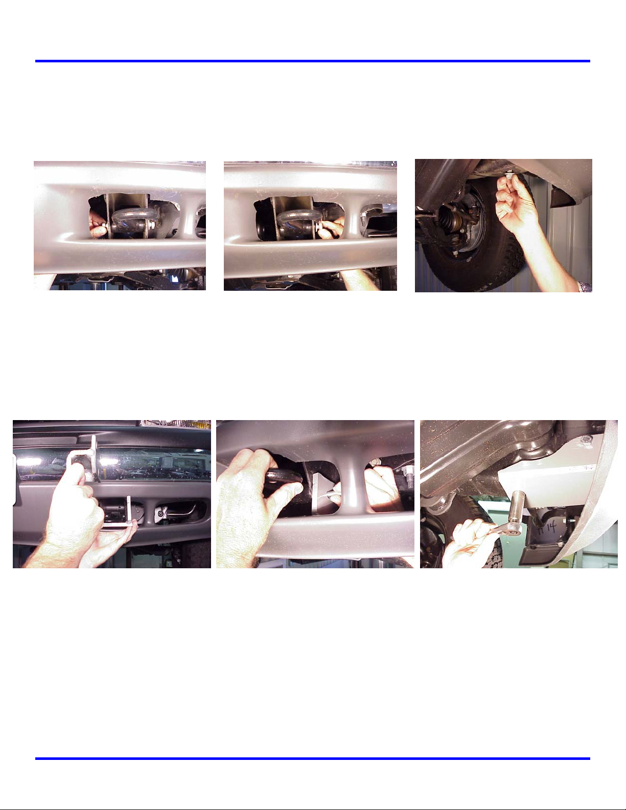
Step 1
Note: It is not necessary to remove or modify the vehicle bumper to install this mounting kit. Remove
and discard the M12 bolts at either side and bottom of the tow hook (Figure 1), remove tow hook and
set aside.
Figure 1
Step 2
Insert left hand frame mounting bracket assembly #7 through air dam. Replace tow hook and secure
using (3) 12 mm bolts #18 (Figure 2). DO NOT TIGHTEN HARDWARE COMPLETELY.
Figure 2
Step 3
Repeat steps 1 & 2 above for right hand side. DO NOT TIGHTEN HARDWARE COMPLETELY.
1
Page 3
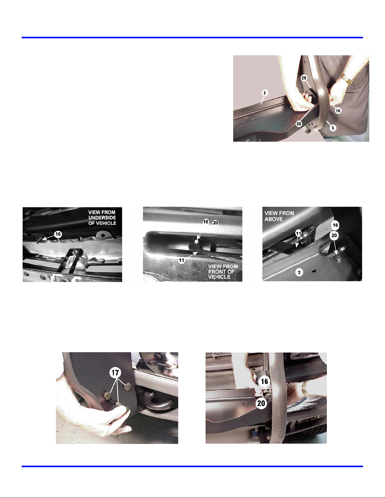
Step 4
Note: You will need assistance for this step.
Have someone hold the center unit while you insert the
winch mounting channel #2 between side plates of center
unit #5. Channel shims #29 are inserted between the end of
the channel and the side plate of the center unit on both
sides. Secure each side of channel using (2) 3/8-16NC x 1
capscrews #16 with nuts #20 (Figure 3).
Step 5
Install upper mounting bracket #11 (Figure 4) on bumper using 3/8” x 1” bolt #16 and secure using
3/8 locknut #20 (Figure 5). Make sure top tab of left hand bracket is pointed toward the left side of
vehicle as shown below. Repeat for right hand side.
Figure 3
Figure 4
Step 6
Mount center unit on vehicle and secure each side at the lower support bracket using (3) 1/2” X 1-1/4”
capscrews #17 with (3) 1/2” nuts #21 (Figure 5). Attach each side of center unit to upper support
bracket using (1) 3/8-16NC x 1 capscrew #16 with nut #20. DO NOT TIGHTEN HARDWARE.
Figure 5
2
Page 4

Note: If you are installing Grille Guard kit #295934, skip Step #7 and proceed
to step #8. Step 7 is for the Wraparound Kit only.
Step 7
Position the wrap shim #31 and the L.H. wraparound #4 with the headlight grille #28 next to the side
plate and align holes. Insert (2) 1/4-20NC x 1-1/4 capscrews #16 through side plate, wrap shim,
wraparound, and headlight grille and secure using 1/4 nuts #20. Do not tighten.
Insert (3) 1/4-20NC x 1
capscrews through holes
above and below headlight
grille #12 and secure using
1/4 nuts #20.
Repeat for right hand side.
Tighten all nuts to proper
torque.
Figure 6
Step 8
Properly align the assembly with the front of the vehicle. Starting with the lower mounting brackets
and working up, tighten all hardware to proper torque. Refer to Torque Table on page 5 for proper
torque values.
If needed, install License Plate Mounting Assembly to bottom of channel using (2) 1/4 x 1” capscrews
#14 and 1/4” locknuts #19. Refer to winch Owner’s Manual for instructions for installing winch and
fairlead using hardware supplied with winch.
3
Page 5

4
Page 6

PARTS LIST
Item # Part # Qty. Description
1 R-CABLETIE 1 Cable tie
2 R-CHANNEL32 1 Winch channel - 32”
3
4
5 R-P295935 1 Center unit
6 R-LM935R 1 Frame mounting bracket - right side
7 R-LM935L 1 Frame mounting bracket – left side
8
9
10 Not Used
11 R-US932 1 Upper support bracket – universal
12 R-G932-L 1 Headlight grille – Left
13 R-G932-R 1 Headlight grille - Right
14 HCS1/4x1 12 Hex capscrew 1/4” x 1”
15 Not Used
16 HCS3/8X1 6 Hex capscrew 3/8” X 1”
17 HCS1/2X1.25 6 Hex capscrew 1/2” X 1-1/4”
18 HCS12mmX40coarse 6 Hex capscrew 12mm X 40mm coarse thread
19 LNUT1/4-20 12 1/4” Lock nut
20 LNUT3/8-16 8 3/8-16 Lock nut
21 LNUT1/2-13 6 1/2-13 Lock nut
22 Not Used
23 Not Used
24 WASHFLT1/4 20 1/4” Flat washer
25 WASHFLT3/8 2 3/8” Flat washer
26
27 R408127 1 License plate mounting assembly
28 R-CABLETIE 1 Cable tie
29 R-SHIM307C 2 Channel shim
30 R-SHIM532US 2 Upper shim
31 R-SHIM932 1 Wraparound shim
32 R-SHIM314LS 2 Lower shim
33 R-LOOM 1 Loom
R-W932R 1 Wrap around - Right
R-W932L 1 Wrap around – Left
Not Used
Not Used
Items in italics are for Wraparound Kit #295935.
TORQUE VALUE CHART
SIZE TORQUE – FT. LBS. TORQUE - Nm
1/4-20 5 7
3/8-16 34 46
1/2-13 87 118
12mm 39 53
5
Page 7

6
 Loading...