

Page 1
INSTALLATION INSTRUCTIONS FOR
SIERRA GRILLE GUARD KIT # 295928
2001 CHEVY SILVERADO / GMC SIERRA 8600# GVW
NOTICE
Ramsey kits are designed for use with Ramsey Winches only.
Use or sales of kits for other winches or applications voids warranty.
WARNING
Ramsey offers mounting kits and winches for various vehicles. In crash tests on a limited number
of automotive manufacturer's vehicles, winches/mounting kits, which have been properly
mounted, have not interfered with air bag operation.
The user/customer, or their installer, must verify that the mounting kit does not interfere with the
factory air bag sensors, which must not be relocated or modified in any way.
The user/customer should follow the vehicle manufacturer's recommendations and those of a
qualified mechanic to determine if the winch/mounting kit might interfere with the air bag
operation. The user/customer should then determine the suitability of a winch/mounting kit on a
particular vehicle.
PLEASE BE ADVISED THAT THE VEHICLE'S AIR BAG SYSTEM MAY NOT OPERATE
PROPERLY IF THE WINCH/MOUNTING KIT IS NOT MOUNTED IN COMPLIANCE WITH THE
VEHICLE MANUFACTURER'S RECOMMENDATIONS.
DO NOT ATTACH TOW HOOK TO ANY PART OF MOUNTING KIT UNLESS INSTRUCTED TO
DO SO.
DO NOT SUBSTITUTE ATTACHING HARDWARE ITEMS (BOLTS, NUTS, OR WASHERS).
READ AND UNDERSTAND WINCH OWNER'S MANUAL BEFORE INSTALLATION AND
OPERATION OF WINCH. SEE WARNING AND CAUTION.
IMPORTANT NOTES!
1. RIGHT AND LEFT HAND DIRECTIONS AS IF SEATED BEHIND STEERING WHEEL.
2. ALL FASTENING HARDWARE MUST BE LOOSELY ASSEMBLED UNTIL DIRECTED TO TIGHTEN.
RAMSEY WINCH COMPANY
P.O. BOX 581510
TULSA, OKLAHOMA 74158
KI-913363-0501-A
Page 2
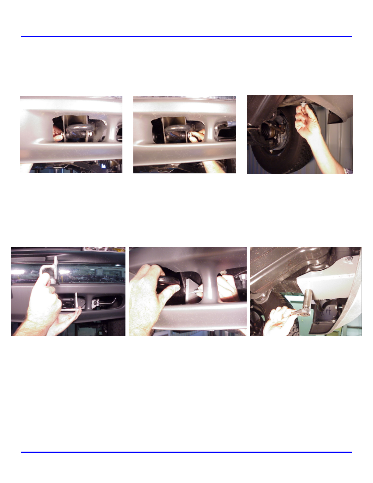
Step 1
Note: It is not necessary to remove or modify the vehicle bumper to install this mounting kit. Remove
and discard the M12 bolts at either side and bottom of the tow hook (Figure 1), remove tow hook and
set aside.
Figure 1
Step 2
Insert left hand frame mounting bracket assembly #7 through air dam. Replace tow hook and secure
using (3) 12 mm bolts #18 and lockwashers # 26 (Figure 2). DO NOT TIGHTEN HARDWARE COMPLETELY.
Figure 2
Step 3
Repeat steps 1 & 2 above for right hand side. DO NOT TIGHTEN HARDWARE COMPLETELY.
KI-913363-0501-A 1
Page 3
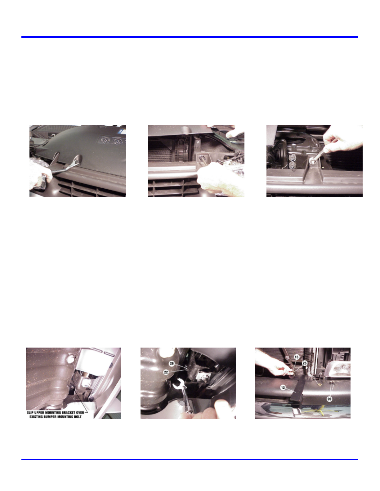
Step 4
It will be necessary to remove vehicle grille to install upper mounting brackets. To remove grille,
open hood and first remove plastic panel on top of grille. Use a door panel removal tool or a flat
screwdriver to remove center pins of plastic rivets that hold panel in place and lift away panel. The
grille can then be easily removed by using a Phillips screwdriver to release (4) plastic grille fasteners
and a 10mm socket wrench to remove center bolt near the hood latch (Figure 3). The outer ends of
grille are snapped in place with metal clips and can be removed by carefully pulling grille until snaps
release.
Figure 3
Step 5
Note: It is not necessary to remove the vehicle bumper to install this kit. Install L.H. upper mounting
bracket #10 (Figure 4) on existing bumper mounting bolt. Bracket must be positioned from the top
with the two slotted holes pointing toward the center of the vehicle. Secure using 1/2” lockwasher #26
and 12 mm nut #22. Tighten using a crow’s foot attachment and ratchet (Figure 4). DO NOT TIGHTEN
HARDWARE COMPLETELY.
Install (1) 3/8-16NC X 1” capscrew #15 through 3/8” flatwasher #25, for each of the holes in top of
upper support bracket #12 (Figure 4). Secure using 3/8” flatwasher #25 and 3/8” nut #20. DO NOT
TIGHTEN HARDWARE COMPLETELY. Reattach the grille and top panel (refer to Step 4 above) before
continuing the installation.
Figure 4
KI-913363-0501-A 2
Page 4

FURNISHED WITH WINCH
Fig
ure 8
FURNISHED WITH WINCH
FURNISHED WITH WINCH
Step 6
Note: You will need assistance for this step.
Have someone hold the center unit while you insert the
winch mounting channel #2 between side plates of center
unit #5. Channel shims #29 are inserted between the end of
the channel and the side plate of the center unit on both
sides. Secure each side of channel using (2) 3/8-16NC x 11/4 capscrews #16 with nuts #20 (Figure 5). Tighten
hardware to proper torque. (See torque value chart, page 8).
Step 7
Figure 5
Mount center unit on vehicle and secure each side at the lower support bracket using (3) 1/2” X 1-1/4”
capscrews #17 with (3) 1/2” nuts #21 (Figure 6). Attach each side of center unit to upper support
bracket using (1) 3/8-16NC x 1-1/4 capscrew #16 with nut #20. DO NOT TIGHTEN HARDWARE.
Step 8
Install fairlead as shown below. Note that top holes in channel (Figure 7) align with bottom holes on
roller fairlead (Figure 8). Secure using capscrew, lockwasher, and nut furnished with winch.
Figure 6
Figure 7
KI-913363-0501-A 3
Page 5

Note:
When mounting the earlier model “REP 6000” winch with solenoid assembly under the motor,
see last page. For all other models, refer to “Installation and Electrical Connections” section of winch
Owner’s Manual.
KI-913363-0501-A 4
Page 6

5 7
34 46
87
39 53
TORQUE VALUE CHART
PARTS LIST
Item # Part # Qty. Description
1 R-CABLETIE 1 Cable tie
2 R-CHANNEL32 1 Winch channel - 32”
3 R-W314R 1 Not Used
4 R-W314L 1 Not Used
5 R-P12314 1 Center unit
6 R-LM312R 1 Frame mounting bracket - right side
7 R-LM312L 1 Frame mounting bracket – left side
8 R-TOPTUBE32 Not Used
9 R-UM556R 1 Upper mounting bracket – right side
10 R-UM556L 1 Upper mounting bracket – left side
11 R-US314R 1 Upper support bracket – right side
12 R-US314L 1 Upper support bracket – left side
13 Not Used
14 HCS1/4-20X1.25 2 Not Used
15 HCS3/8X1 4 Hex capscrew 3/8” X 1”
16 HCS3/8X1.25 6 Hex capscrew 3/8” X 1-1/4”
17 HCS1/2X1.25 6 Hex capscrew ½” X 1-1/4”
18 HCS12X50 6 Hex capscrew 12mm X 50mm
19 LNUT1/4-20 2 Not Used
20 LNUT3/8-16 10 3/8-16 Lock nut
21 LNUT1/2-13 6 1/2-13 Lock nut
22 HEXNUT12MM 2 12 MM hex nut
23 WASHFLTPL1/4 2 Not Used
24 Not Used
25 WASHFLT3/8 8 3/8” Flatwasher
26 WASHLOC1/2 8 1/2” Lockwasher
27 R-G314R Not Used
28 R-G314L Not Used
29 R-SHIM314C 2 Channel shim
30 R-SHIM314U 2 Upper shim
31 R-SHIM314W Not Used
32 R-SHIM314L 2 Lower shim
33 R-LOOM 1 Loom
SIZE TORQUE – FT. LBS. TORQUE - Nm
¼-20
3/8-16
1/2-13
12mm
118
KI-913363-0501-A 5
Page 7

KI-913363-0501-A 6
Page 8

INSTRUCTIONS FOR MOUNTING AN EARLIER MODEL REP 6000 WINCH (SOLENOID ASSEMBLY
UNDER THE MOTOR) TO A RAMSEY BUMPER, GRILLE GUARD, OR HIDDEN / ORIGINAL KIT.
REP-6000 WINCH
ROLLER FAIRLEAD
(FURNISHED WITH WINCH)
WINCH MOUNTING HARDWARE
(FURNISHED WITH WINCH)
BUMPER MOUNT
REP-6000
WINCH
REP-6000
WINCH
HIDDEN/ORIGINAL MOUNT
GRILLE GUARD MOUNT
MOUNTING HARDWARE
FURNISHED WITH WINCH
KI-913363-0501-A 7
 Loading...