

Page 1
Page 2
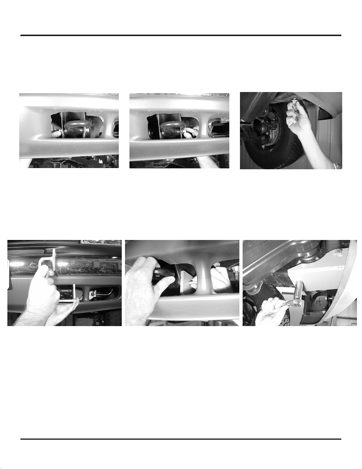
Step 1
Note: It is not necessary to remove or modify the vehicle bumper to install this mounting kit. Remove
and discard the M12 bolts on either side and bottom of the tow hook (Figure 1), remove tow hook
and set aside.
Figure 1
Step 2
Insert left hand frame mounting bracket assembly #7 through air dam. Replace tow hook and secure
using (3) 12 mm bolts #18 and lockwashers # 26 (Figure 2). DO NOT TIGHTEN HARDWARE COMPLETELY.
Figure 2
Step 3
Repeat steps 1 & 2 above for right hand side. DO NOT TIGHTEN HARDWARE COMPLETELY.
1
KI-913356-0301-C
Page 3
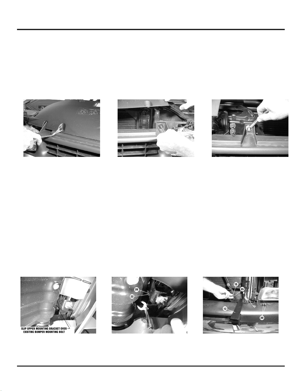
Step 4
It will be necessary to remove vehicle grille to install upper mounting brackets. To remove grille,
open hood and first remove plastic panel on top of grille. Use a door panel removal tool or a flat
screwdriver to remove center pins of plastic rivets that hold panel in place and lift away panel. The
grille can then be easily removed by using a Phillips screwdriver to release (4) plastic grille fasteners
and a 10mm socket wrench to remove center bolt near the hood latch (Figure 3). The outer ends of
grille are snapped in place with metal clips and can be removed by carefully pulling grille until snaps
release.
Figure 3
Step 5
Note: It is not necessary to remove the vehicle bumper to install this kit. Install L.H. upper mounting
bracket #10 (Figure 4) on existing bumper mounting bolt. Bracket must be positioned from the top
with the two slotted holes pointing toward the center of the vehicle. Secure using 1/2” lockwasher #26
and 12 mm nut #22. Tighten using a crow’s foot attachment and ratchet (Figure 4). DO NOT TIGHTEN
HARDWARE COMPLETELY.
Install (1) 3/8-16NC X 1” capscrew #15 through 3/8” flatwasher #25, for each of the holes in top of
upper support bracket #12 (Figure 4). Secure using 3/8” flatwasher #25 and 3/8” nut #20. DO NOT
TIGHTEN HARDWARE COMPLETELY. Reattach the grille and top panel (refer to Step 4 above) before
continuing the installation.
Figure 4
2
KI-913356-0301-C
Page 4

Step 6
Note: You will need assistance for this step.
Have someone hold the center unit while you insert the
winch mounting channel #2 between side plates of center
unit #5. Channel shims #29 are inserted between the end of
the channel and the side plate of the center unit on both
sides. Secure each side of channel using (2) 3/8-16NC x 11/4 capscrews #16 with nuts #20 (Figure 5). Note: Do not
tighten hardware at this location, as you will need to remove
these nuts to install the wraparound in a later step.
Figure 5
Step 7
Mount center unit on vehicle and secure each side at the lower support bracket using (3) 1/2” X 1-1/4”
capscrews #17 with (3) 1/2” nuts #21 (Figure 6). Attach each side of center unit to upper support
bracket using (1) 3/8-16NC x 1-1/4 capscrew #16 with nut #20. DO NOT TIGHTEN HARDWARE.
Figure 6
Step 8
Remove the two nuts #19 securing the headlight grille #28 to
the L.H. wraparound #4. It is not necessary to remove the
capscrews #14 or flat washers #23 (Figure 7).
3
Figure 7
KI-913356-0301-C
Page 5

Step 9
Repeat Steps 5-8 above for right hand side. DO NOT TIGHTEN HARDWARE COMPLETELY.
Step 10
Note: You will need assistance for this step.
Remove the (3) 3/8-16NC x 1-1/4” capscrews #16 from L.H. side of center unit where the side plate
attaches to the upper support bracket and the channel (Figure 8).
Have someone position wrap shim #31 between the side plate and left wraparound #4 (Figure 9).
Align the (2) 1/4-20NC x 1-1/4 capscrews #14 holding the headlight grille to the wraparound with the
appropriate holes in the side plate and slide into place (Figure 9). Secure using (2) 1/4” nuts #19.
Figure 8
Step 11
Re-insert (2) 3/8-16NC x 1-1/4 capscrews #16
through light tube, shim, side plate, and channel and
(1) 3/8-16NC x 1-1/4 capscrew #16 through light
tube, shim, side plate, and upper support bracket
and secure each with nut #21 (Figure 10).
Tighten all hardware to proper torque. (See torque
value chart, page 8).
4
Figure 9
Figure 10
KI-913356-0301-C
Page 6

Step 12
Insert top bar #8 into tube at top of L.H. wraparound #4 (Figure11). Align top tube of R.H.
wraparound # 3 with opposite end of top bar #8 (Figure 12). Refer to Steps 10 &11 to complete
installation of R.H. wraparound.
Figure 11
Figure 12
Step 13
Install fairlead as shown below. Note that top holes in channel (Figure 13) align with bottom holes on
roller fairlead (Figure 14). Secure using capscrew, lockwasher, and nut furnished with winch.
FURNISHED WITH WINCH
FURNISHED WITH WINCH
FURNISHED WITH WINCH
Figure 13
Figure 14
5
KI-913356-0301-C
Page 7

Note:
When mounting the earlier model “REP-6000” winch with solenoid assembly under the motor, see
last page. For all other models, refer to “Installation and Electrical Connections” section of winch
owner’s manual.
6
KI-913356-0301-C
Page 8

PARTS LIST
Item # Part # Qty. Description
1 R-CABLETIE 1 Cable tie
2 R-CHANNEL32 1 Winch channel - 32”
3 R-W314R 1 Wraparound – right
4 R-W314L 1 Wraparound – left
5 R-P12314 1 Center unit
6 R-LM312R 1 Frame mounting bracket - right side
7 R-LM312L 1 Frame mounting bracket – left side
8 R-TOPTUBE32 1 Top bar – 32”
9 R-UM556R 1 Upper mounting bracket – right side
10 R-UM556L 1 Upper mounting bracket – left side
11 R-US314R 1 Upper support bracket – right side
12 R-US314L 1 Upper support bracket – left side
13 Not Used
14 HCS1/4-20X1.25 6 Hex capscrew 1/4” X 1-1/4”
15 HCS3/8X1 4 Hex capscrew 3/8” X 1”
16 HCS3/8X1.25 6 Hex capscrew 3/8” X 1-1/4”
17 HCS1/2X1.25 6 Hex capscrew ½” X 1-1/4”
18 HCS12X50 6 Hex capscrew 12mm X 50mm
19 LNUT1/4-20 6 ¼-20 Lock nut
20 LNUT3/8-16 10 3/8-16 Lock nut
21 LNUT1/2-13 6 1/2-13 Lock nut
22 HEXNUT12MM 2 12 MM hex nut
23 WASHFLTPL1/4 6 ¼” Plastic washer
24 Not Used
25 WASHFLT3/8 8 3/8” Flatwasher
26 WASHLOC1/2 8 1/2” Lockwasher
27 R-G314R 1 Headlight grille – right
28 R-G314L 1 Headlight grille – left
29 R-SHIM314C 2 Channel shim
30 R-SHIM314U 2 Upper shim
31 R-SHIM314W 2 Wrap shim
32 R-SHIM314L 2 Lower shim
33 R-LOOM 1 Loom
TORQUE VALUE CHART
SIZE TORQUE – FT. LBS. TORQUE - Nm
1/4-20 5 7
3/8-16 34 46
1/2-13 87 118
12mm 39 53
7
KI-913356-0301-C
Page 9

8
KI-913356-0301-C
Page 10

 Loading...