

Page 1
INSTALLATION INSTRUCTIONS FOR
SIERRA WRAPAROUND KIT # 295922
1999-2002 CHEVY SILVERADO/GMC SIERRA 1500
2000-2006 CHEVY SUBURBAN 1500/TAHOE
2000-2006 GMC YUKON 1500/ YUKON XL
NOTICE
Ramsey kits are designed for use with Ramsey Winches only.
Use or sales of kits for other winches or applications voids warranty.
WARNING
Ramsey offers mounting kits and winches for various vehicles. In crash tests on a limited number of automotive
manufacturer's vehicles, winches/mounting kits, which have been properly mounted, have not interfered with air
bag operation.
The user/customer, or their installer, must verify that the mounting kit does not interfere with the factory air bag
sensors, which must not be relocated or modified in any way.
The user/customer should follow the vehicle manufacturer's recommendations and those of a qualified mechanic
to determine if the winch/mounting kit might interfere with the air bag operation. The user/customer should then
determine the suitability of a winch/mounting kit on a particular vehicle.
PLEASE BE ADVISED THAT THE VEHICLE'S AIR BAG SYSTEM MAY NOT OPERATE PROPERLY IF THE
WINCH/MOUNTING KIT IS NOT MOUNTED IN COMPLIANCE WITH THE VEHICLE MANUFACTURER'S
RECOMMENDATIONS.
DO NOT ATTACH TOW HOOK TO ANY PART OF MOUNTING KIT UNLESS INSTRUCTED TO DO SO.
DO NOT SUBSTITUTE ATTACHING HARDWARE ITEMS (BOLTS, NUTS, OR WASHERS).
READ AND UNDERSTAND WINCH OWNER'S MANUAL BEFORE INSTALLATION AND OPERATION OF WINCH.
SEE WARNING AND CAUTION.
IMPORTANT NOTES!
1. RIGHT AND LEFT HAND DIRECTIONS AS IF SEATED BEHIND STEERING WHEEL.
2. ALL FASTENING HARDWARE MUST BE LOOSELY ASSEMBLED UNTIL DIRECTED TO TIGHTEN.
RAMSEY WINCH COMPANY
P.O. BOX 581510
TULSA, OKLAHOMA 74158
KI-913354-0307-G
Page 2
Step 1
Note: It is not necessary to remove or modify the vehicle bumper to install this mounting kit. Remove
the M12 nut to the cross bolt on the tow hook and slide the bolt back. Remove lower M12 bolt for tow
hook on bottom of vehicle frame. It is not necessary to remove the tow hook.
Figure 1
Figure 2
Step 2
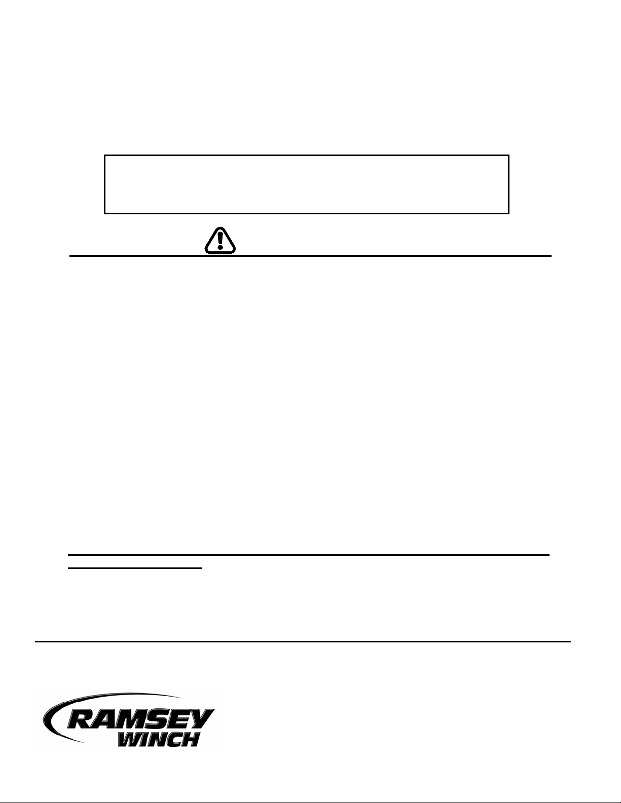
Align L.H. frame mounting bracket #7 with underside of vehicle frame (Figure 3), slide tow hook bolt
back into place and secure with M12 nut (Figure 4). Make sure that tab on bracket is to the inside
edge of frame. Replace lower M12 mounting bolt (Figure 5). DO NOT TIGHTEN HARDWARE
COMPLETELY.
Figure 3
Figure 4
Figure 5
1
Page 3
Step 3
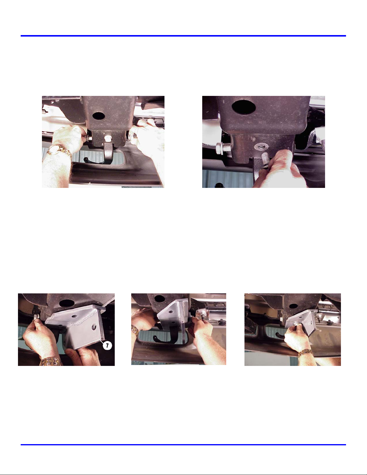
Drill 17/32” hole in vehicle frame using rear hole in frame mounting bracket as a template (Figure 6).
Install ½” nut #22 through existing access hole in bottom of vehicle frame (Figure 7). Using a
standard combination wrench to hold the nut in place, thread (1) ½-13NC X 1-1/4” capscrew #19 into
nut (Figure 8). DO NOT TIGHTEN HARDWARE COMPLETELY.
Figure 6
Figure 7
Figure 8
2
Page 4

Step 4
Note: It is not necessary to remove the vehicle bumper to install this kit.
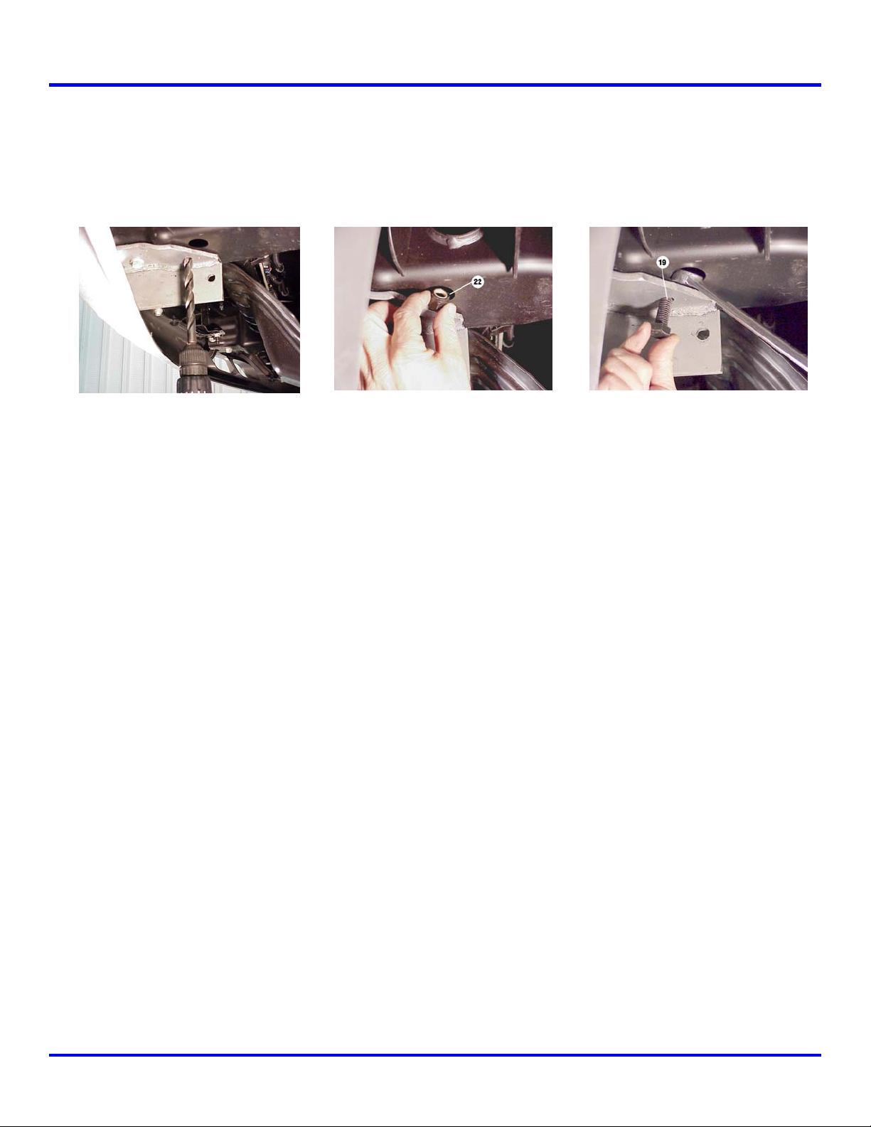
Install L.H. upper mounting bracket #9 on existing bumper mounting bolt (see Figure 9). Bracket
must be positioned from the top with the two slotted holes pointing toward the center of the vehicle.
Secure using 12 mm nut #19 (see Figure 10). Tighten using a crow’s foot attachment and ratchet.
DO NOT TIGHTEN HARDWARE COMPLETELY.
9
19
Figure 9
Figure 10
Install (1) 3/8-16NC X 1” capscrew #13 through 3/8” flatwasher #21, for each of the holes in the
upper support bracket #11, bolting the upper mounting bracket #8 to the upper support bracket #11
so the upper support bracket sits over the vehicle bumper, as shown in Figure 11. Secure using 3/8”
flatwasher #21 and 3/8” nut #17. Figure 12 shows the upper mounting bracket viewed from the top
with the grille removed for clarity. DO NOT TIGHTEN HARDWARE COMPLETELY.
11
9
Figure 11
3
Figure 12
Page 5

Repeat Steps 1-4 for right side of truck.
Make sure the tabs on the upper support brackets are in the
correct position (Figure 11).
Step 5
Slide lower L.H. mounting bracket #10 between tow hook and
frame mounting bracket #7 (Figure 13). Position lower
mounting shim #33 between the two brackets and secure using
(2) 1/2-13NC X 1-1/4” capscrews #19 and (2) 1/2” nuts #22
(Figure 14). DO NOT TIGHTEN HARDWARE COMPLETELY.
Step 6
Figure 13
Figure 14
Note: You will need assistance for this step.
Have someone hold the center unit while you insert the winch mounting channel #2 between side
plates of center unit #5. Channel shims #29 are inserted between the end of the channel and the
side plate of the center unit on both sides. Secure each side of channel using (2) 3/8-16NC x 1-1/4
capscrews #18 with nuts #21 (Figure 15). Note: Do not tighten hardware at this location, as you will
need to remove these nuts to install the wraparound in a later step.
Figure 15
Step 7
Mount center unit on vehicle and secure each side at the lower support bracket using (3) 1/2” X 1-1/4”
capscrews #19 with (3) 1/2” nuts #22 (Figure 16). Attach each side of center unit to upper support
bracket using (1) 3/8-16NC x 1-1/4 capscrew #18 with nut #21 (Figure 17). Do not tighten hardware.
Figure 16 Figure 17
4
Page 6

Step 8
Remove the two nuts #20 that secure the headlight grille to the L.H. wraparound #4. It is not
necessary to remove the capscrews (Figure 18).
Step 9
Note: You will need assistance for this step.
Remove the (3) 3/8-16NC x 1-1/4” capscrews #18 from L.H. side
of center unit where the side plate attaches to the upper support
bracket and the channel (Figure 18).
Have someone position wrap shim #31 between the side plate and
left wraparound #4.
Align the (2) 1/4-20NC x 1-1/4 capscrews #16 holding the
headlight grille to the wraparound with the appropriate holes in the
side plate and slide into place (Figure 19). Secure using (2) 1/4”
nuts #20.
Figure 18
Figure 19
Figure 20
Step 10
Re-insert (2) 3/8-16NC x 1-1/4 capscrews #18 through light tube,
shim, side plate, and channel and (1) 3/8-16NC x 1-1/4
capscrews #18 through light tube, shim, side plate, and upper
support bracket and secure all with nut #21 (Figure 21).
Tighten all hardware to proper torque. (See torque value chart,
page 8).
Install (1) ¼-20NC x 1-1/4
capscrew #16 through upper hole
in wraparound and into side plate.
Secure using (1) 1/4” nut #20
(Figure 20). Do not tighten.
5
Figure 21
Page 7

Step 11
Insert top bar #8 into tube at top of L.H. wraparound #4 (Figure22). Align top tube of R.H.
wraparound # 3 with opposite end of top bar #8 (Figure 23).
Follow instructions in Step 9 and 10 to complete mounting of R.H. wraparound.
Figure 22
Figure 23
Step 12
Install fairlead as shown below. Note that top holes in channel (Figure 24) align with bottom holes on
roller fairlead (Figure 25). Secure using capscrew, lockwasher, and nut furnished with winch.
FURNISHED WITH WINCH
FURNISHED WITH WINCH
FURNISHED WITH WINCH
Figure 24
Figure 25
6
Page 8

7
Page 9

PARTS LIST
Item # Part # Qty. Description
1 Not Used
2 R-CHANNEL32 1 Winch channel - 32”
3 R-W314R 1 Wraparound – right
4 R-W314L 1 Wraparound – left
5 R-P12314 1 Center unit
6 R-LM314R 1 Frame mounting bracket - right side
7 R-LM314L 1 Frame mounting bracket – left side
8 R-TOPTUBE32 1 Top bar – 32”
9 R-LS314R 1 Lower support bracket – right side
10 R-LS314L 1 Lower support bracket – left side
11 R-UM566R 1 Upper mounting bracket – right side
12 R-UM566L 1 Upper mounting bracket – left side
13 R-US314R 1 Upper support bracket – right side
14 R-US314L 1 Upper support bracket – left side
15 Not Used
16 HCS1/4-20X1.25 6 Hex capscrew 1/4” X 1-1/4”
17 HCS3/8X1 6 Hex capscrew 3/8” X 1”
18 HCS3/8X1.25 6 Hex capscrew 3/8” X 1-1/4”
19 HCS1/2X1.25 12 Hex capscrew ½” X 1-1/4”
20 LNUT1/4-20 6 ¼-20 Lock nut
21 LNUT3/8-16 12 3/8-16 Lock nut
22 LNUT1/2-13 12 1/2-13 Lock nut
23 HEXNUT12MM 2 12 MM hex nut
24 WASHFLTPL1/4 6 ¼” Plastic washer
25 Not Used
26 WASHFLT3/8 12 3/8” Flatwasher
27 R-G314R 1 Headlight grille – right
28 R-G314L 1 Headlight grille – left
29 R-SHIM314C 2 Channel shim
30 R-SHIM314U 2 Upper shim
31 R-SHIM314W 2 Wrap shim
32 R-SHIM314L 2 Lower shim
33 R-SHIM314LM 2 Lower mounting shim
34 R-LOOM 1 Loom
35 R-CABLETIE 2 Cable tie
TORQUE VALUE CHART
SIZE TORQUE – FT. LBS. TORQUE - Nm
¼-20 5 7
3/8-16 34 46
1/2-13 87 118
12mm 39 53
8
Page 10

12
11
9
 Loading...