

Page 1
INSTALLATION INSTRUCTIONS FOR
SIERRA WRAPAROUND KIT # 295918
1999-2001 FORD EXPLORER
NOTICE
Ramsey kits are designed for use with Ramsey Winches only.
Use or sales of kits for other winches or applications voids warranty.
WARNING
Ramsey offers mounting kits and winches for various vehicles. In crash tests on a limited number
of automotive manufacturer's vehicles, winches/mounting kits, which have been properly
mounted, have not interfered with air bag operation.
The user/customer, or their installer, must verify that the mounting kit does not interfere with the
factory air bag sensors, which must not be relocated or modified in any way.
The user/customer should follow the vehicle manufacturer's recommendations and those of a
qualified mechanic to determine if the winch/mounting kit might interfere with the air bag
operation. The user/customer should then determine the suitability of a winch/mounting kit on a
particular vehicle.
PLEASE BE ADVISED THAT THE VEHICLE'S AIR BAG SYSTEM MAY NOT OPERATE
PROPERLY IF THE WINCH/MOUNTING KIT IS NOT MOUNTED IN COMPLIANCE WITH THE
VEHICLE MANUFACTURER'S RECOMMENDATIONS.
DO NOT ATTACH TOW HOOK TO ANY PART OF MOUNTING KIT UNLESS INSTRUCTED TO
DO SO.
DO NOT SUBSTITUTE ATTACHING HARDWARE ITEMS (BOLTS, NUTS, OR WASHERS).
READ AND UNDERSTAND WINCH OWNER'S MANUAL BEFORE INSTALLATION AND
OPERATION OF WINCH. SEE WARNING AND CAUTION.
IMPORTANT NOTES!
1. RIGHT AND LEFT HAND DIRECTIONS AS IF SEATED BEHIND STEERING WHEEL.
2. ALL FASTENING HARDWARE MUST BE LOOSELY ASSEMBLED UNTIL DIRECTED TO TIGHTEN.
RAMSEY WINCH COMPANY
P.O. BOX 581510
TULSA, OKLAHOMA 74158
KI-913348-0301-B
Page 2
Step 1
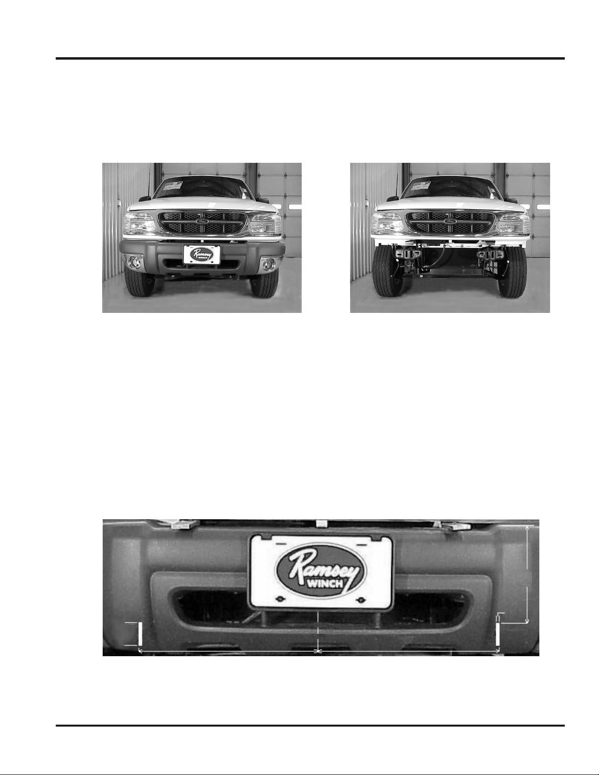
Unplug fog lights, if so equipped and remove vehicle bumper. (Figure 1 & 2).
Figure 1
Figure 2
Step 2
Modify bumper (Figure 3) to allow for frame mounting brackets. First, find the center of the
vehicle bumper. Measure over toward the driver’s side 16.44” and mark the outside edge of the
cutout. Measure back toward the center of the vehicle .5” and mark the inside edge of the
cutout. Measure down 8.00” from the highest point at the top of the bumper and make a mark.
This will be the top of the first cutout. Next measure 4.00” down from your first mark and locate
the bottom of the cutout. Using a keyhole saw or utility knife, cut through the bumper. Ragged
edges can be smoothed using a file or sandpaper. Repeat for the passenger side cutout. When
finished, cutouts should be spaced 32.875” from outside edge to outside edge.
8.00”
.5”
4.00”
16.44”
C
L
”
Figure 3
1
KI-913348-0301-B
Page 3
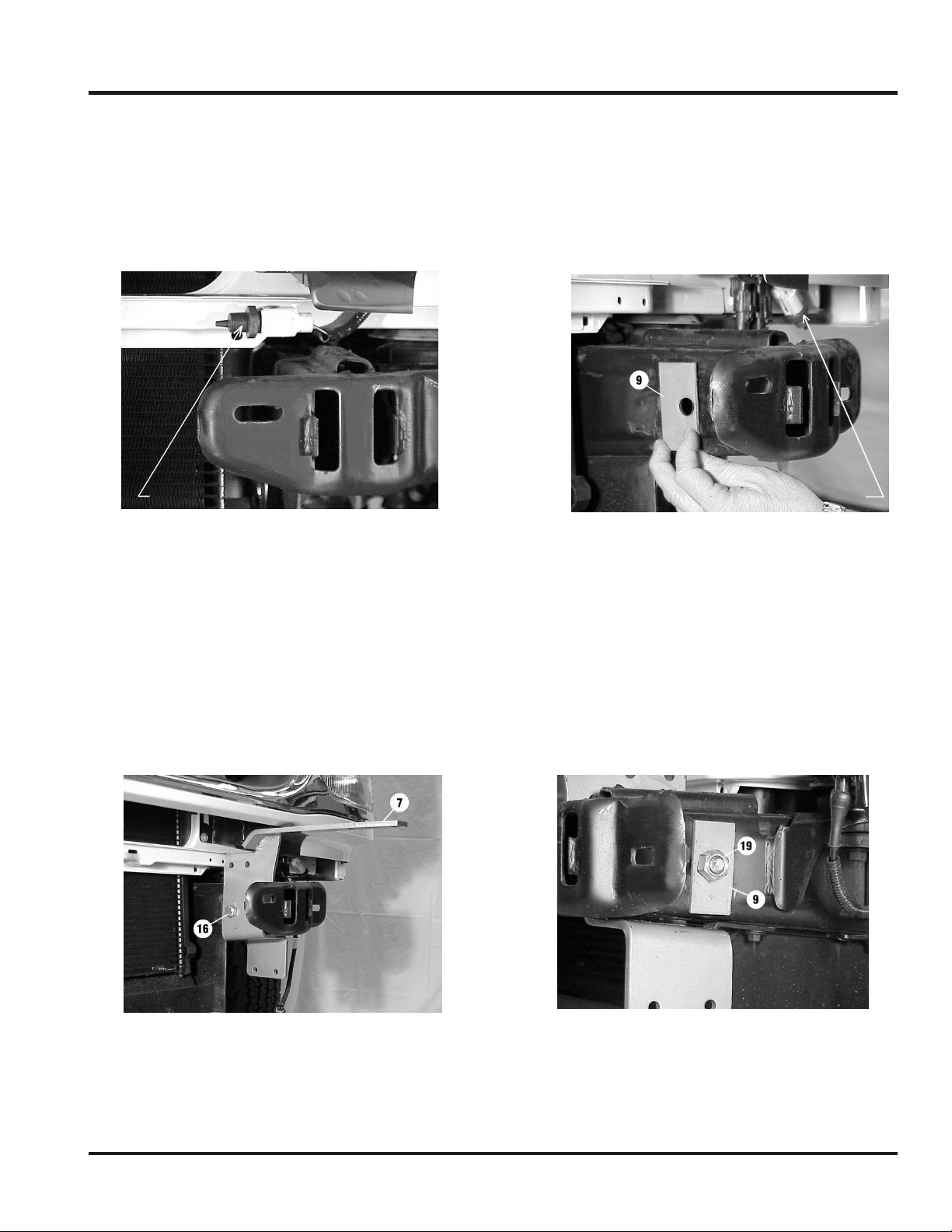
Step 3
Relocate the accessory plug from the inside of the L.H. vehicle frame to the outside using the
existing mounting holes. The accessory plug is shown in the factory installed position (Figure 4).
Note the relocated position on the outside of the vehicle frame (Figure 5).
Place spacer #9 (Figure 5) between frame and L.H. bracket assembly #7 (Figure 6).
ACCESSORY PLUG
Figure 4
ACCESSORY PLUG IN NEW LOCATION
Figure 5
Step 4
Place L.H. bracket assembly #7 over inside and bottom of frame (Figure 6). Secure brackets to
frame using (1) 9/16-12NC x 4-1/4 lg. capscrew #16 through spacer #9, vehicle frame, second
spacer #9, and secure with locknut #19. (Figure 7).
Figure 6
Figure 7
2
KI-913348-0301-B
Page 4

Step 5
Use (1) 9/16-12NC x 1-1/2 lg. capscrew #15 with flatwasher #22, lockwasher #21, and nut
extender #10 to attach bracket assembly to bottom of frame (Figures 8-11). Nut extender and
flatwasher are installed inside of frame through hole in front of frame. It is easier to insert the
washers using a pair of needle nosed pliers (Figure 10).
Figure 8
Figure 10
Figure 9
Figure 11
3
KI-913348-0301-B
Page 5

Step 6
Repeat steps 3-5 for R.H. side of vehicle frame. It may be
necessary to trim or file away a small portion of the fiberglass
(Figure 12). This will prevent the frame mounting brackets from
rubbing. TIGHTEN ALL HARDWARE TO PROPER TORQUE
VALUE (See Torque Value Chart, page 9).
Trim here if needed for clearance
Figure 12
Step 7
Place angle #8 on top of L.H. frame and against bracket assembly. Use holes in bracket
assembly as a guide to centerpunch and drill (2) 7/16 dia. holes in angle. Secure angle to
bracket using (2) 3/8-16NC x 1-1/4 lg. capscrews #13 with locknuts #18. Repeat for R.H. side.
TIGHTEN ALL HARDWARE TO PROPER TORQUE VALUE (See Torque Value Chart, page 9).
Figure 13
Step 8
Reinstall vehicle bumper.
Figure 14
4
KI-913348-0301-B
Page 6

Step 9
Note: You will need assistance for this step.
Have someone steady the center unit while you insert winch
mounting channel #2 between side plates of center unit #5.
Channel shims #26 are inserted between the end of the channel
and the side plate of the center unit on both sides. Use a rubber
mallet to tap the channel into place. Secure channel using (2) 3/816NC x 1-1/2 lg. hx.hd. capscrews #14 with locknuts #18 (each
side). Note: Do not tighten hardware at this location as you will
need to remove these capscrews in a later step.
Step 10
Insert the lower tabs of the center unit through the cutouts in the bumper. Position upper shims
#30 on top of the frame mounting brackets, then secure the channel to the frame mounting
brackets (Figure 16). Use (2) 3/8-16NC X 1-1/4” capscrews #13 with locknuts #18 each side. Do
not tighten hardware. Slip lower shim #34 between the lower tab on side plate and the frame
mounting bracket (Figure 17). Install (2) 3/8-16NC X 1-1/4” capscrews #13 through lower holes
in L.H. side plate and frame mounting bracket (Figure 17). Secure with nuts #18. Repeat for
R.H. side.
Figure 15
Figure 16
Figure 17
5
KI-913348-0301-B
Page 7

Step 11
Note: You will need assistance for this step.
Remove (2) 3/8-16NC x 1-1/2” lg. hx. hd. capscrews #14 from
L.H. side of center unit where channel attaches to side plate.
Remove the two nuts #17, plastic washers #20, and capscrews
#12 that secure the headlight grille to the wraparound #4.
Have someone position wrap shim #33 between the side plate
and wraparound. Install (1) ¼-20NC x 1” lg. hx. hd. capscrew
#12 through upper hole in wraparound and into side plate.
Secure using nut #17. Do not tighten.
Re-insert (2) 3/8-16NC x 1-1/2” lg. hx. hd. capscrews #14 through light tube, shim, side plate, and
channel and secure with nut #18 (Figure 18). Tighten all hardware to proper torque. (See torque
value chart, page 9).
Re-insert (2) ¼-20NC x 1” lg. hx. hd. capscrews #12 through plastic washers #20, headlight grille,
wraparound, and side plate. Secure using nut #17. Tighten to proper torque.
Repeat for R.H. side.
Figure 18
Step 12
Install fairlead as shown below. Note that top holes in channel (Figure 19) align with bottom
holes on roller fairlead (Figure 20). Secure using capscrew, lockwasher, and nut furnished with
winch.
FURNISHED WITH WINCH
Figure 19
FURNISHED WITH WINCH
Figure 20
6
KI-913348-0301-B
Page 8

7
KI-913348-0301-B
Page 9

PARTS LIST
Item # Part # Qty. Description
1 R-LICENSE 1 License plate bracket
2 R-CHANNEL32 1 Winch channel - 32”
3 R-W317R 1 Wraparound – right
4 R-W317L 1 Wraparound – left
5 R-P12317 1 Center unit
6 R-LM317R 1 Frame mounting bracket - right side
7 R-LM317L 1 Frame mounting bracket – left side
8 R-US317 2 Angle
9 R-SP317 4 Spacer
10 R-NUTEXT 2 9/16” Nut extender
11 HCS1/4-20X3/4 2 Hex capscrew 1/4” X 3/4”
12 HCS1/4-20X1 6 Hex capscrew 1/4” X 1”
13 HCS3/8X1.25 12 Hex capscrew 3/8” X 1-1/4”
14 HCS3/8X1.50 4 Hex capscrew 3/8” X 1-1/2”
15 HCS9/16X1.5 2 Hex capscrew 9/16” X 1-1/2”
16 HCS9/16X4.25 2 Hex capscrew 9/16” X 4-1/4”
17 LNUT1/4-20 8 ¼-20 Lock nut
18 LNUT3/8-16 16 3/8-16 Lock nut
19 LNUT9/16-13 2 9/16-13 Lock nut
20 WASHFLTPL1/4 6 ¼” Plastic washer
21 WASHLOC9/16 2 9/16” Lockwasher
22 WASHFLT9/16 2 9/16” Flatwasher
23 R-CABLETIE 2 Cable tie
24 R-G317R 1 Headlight grille – right
25 R-G317L 1 Headlight grille – left
26 R-SHIM317C 2 Channel shim
30 R-SHIM317U 2 Upper shim
32 R-LOOM 1 Loom
33 R-SHIM317W 2 Wrap shim
34 R-SHIM317L 2 Lower shim
8
KI-913348-0301-B
Page 10

TORQUE VALUE CHART
SIZE TORQUE – FT. LBS. TORQUE - Nm
¼-20 5 7
3/8-16 34 46
9/16-12 95 130
9
KI-913348-0301-B
 Loading...