

Page 1

INSTALLATION INSTRUCTIONS
FOR GRILLE GUARD KIT #295372 AND
WRAP-AROUND KIT #295373 FOR RE WINCHES
ON 2005-7 FORD EXCURSION / SUPER-DUTY TRUCKS
Notice
Ramsey kits are designed for use with Ramsey Winches only.
Use or sale of kits for other winches or applications voids warranty.
Warning
Ramsey offers mounting kits and winches for various vehicles. In crash tests on a limited number of automotive
manufacturer’s vehicles, winches/mounting kits, which have been properly mounted, have not interfered with air bag
operation.
The user/customer, or their installer, must verify that the mounting kit does not interfere with the factory air bag sensors, which must not be relocated or modified in any way.
The user/customer should follow the vehicle manufacturer’s recommendations and those of a qualified mechanic to
determine if the winching/mounting kit might interfere with the air bag operation. The user/customer should then
determine the suitability of a winch/mounting kit on a particular vehicle.
PLEASE BE ADVISED THAT THE VEHICLE’S AIR BAG SYSTEM MAY NOT OPERATE PROPERLY IF THE
WINCH/MOUNTING KIT IS NOT MOUNTED IN COMPLIANCE WITH THE VEHICLE MANUFACTURER’S RECOMMENDATIONS.
DO NOT ATTACH TOW HOOK TO ANY PART OF MOUNTING KIT UNLESS INSTRUCTED TO DO SO.
DO NOT SUBSTITUTE ATTACHING HARDWARE ITEMS (BOLTS, NUTS, OR WASHERS).
READ AND UNDERSTAND WINCH OWNER’S MANUAL BEFORE INSTALLATION AND OPERATION OF THE WINCH.
SEE WARNINGS AND CAUTIONS IN WINCH OWNER’S MANUAL.
IMPORTANT NOTES!
1. RIGHT AND LEFT HAND DIRECTIONS AS IF SEATED BEHIND STEERING WHEEL.
2. ALL FASTENING HARDWARE MUST BE LOOSELY ASSEMBLED UNTIL DIRECTED TO TIGHTEN.
RAMSEY WINCH COMPANY
P.O. BOX 581510
TULSA, OKLAHOMA 74158
PHONE: (918) 438-2760 • FAX: (918) 438-6888
http://www.ramsey.com
913396-0307-B
Page 2
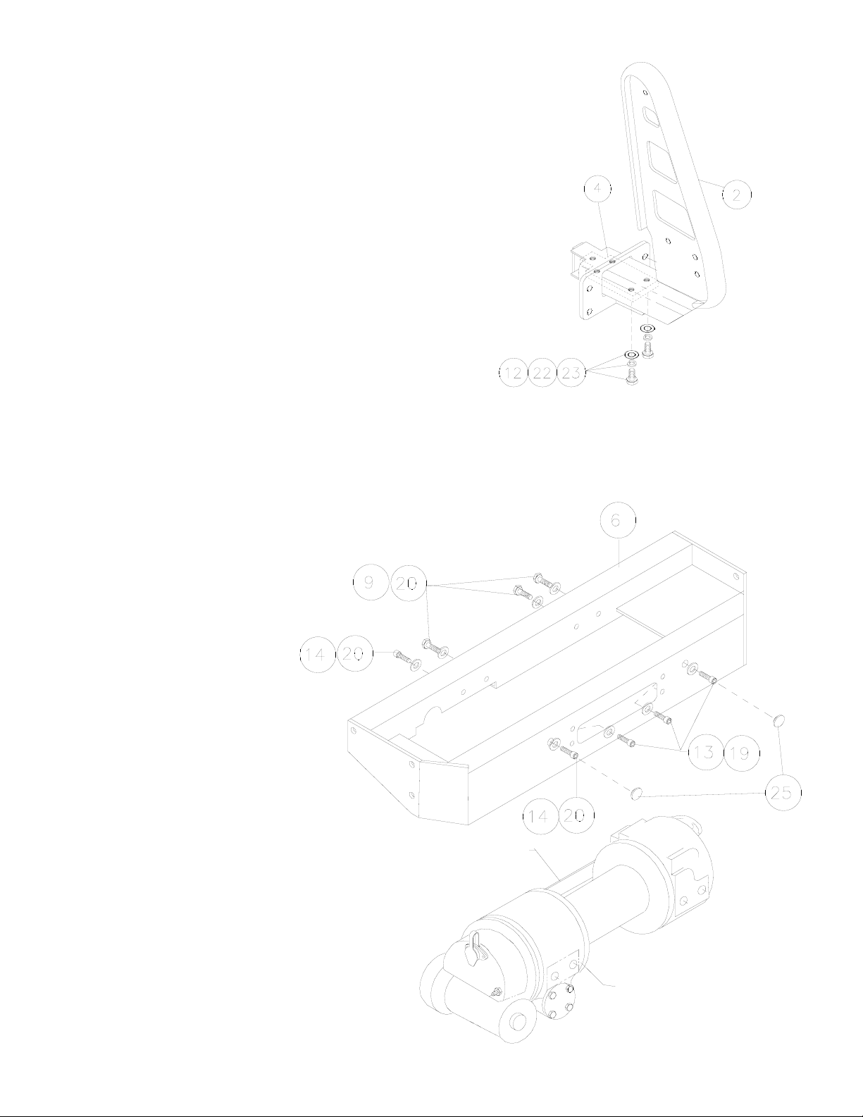
DO NOT FULLY TIGHTEN HARDWARE UNTIL LATER!
1. Attach (1) nut plate (item #4) loosely to inside of L.H.
mounting arm (item #2) using (2) 1/2-13NC X 1.25 capscrews (item #12), (2) flat washers (item #23), and (2)
lockwashers (item #22). See figure at right. Repeat for
R.H. mounting arm (item #1).
2. Remove shipping strap and mounting bolts from winch
assembly and discard. Place mounting channel (item #6)
over top of winch. Secure winch to rear angle of channel
using (3) 3/8-16NC x 1 capscrews (item #9) with lockwashers (item #19) and (1) 3/8-16NC x .75 socket-head
capscrew (item #14) with Hi-collar lockwasher (item
#20) for each.
3. Attach winch to front of channel using (3) 3/8-16NC x 1
socket-head capscrews (item #13) with Hi-collar lockwashers (item #20) and (1) 3/8NC x 3/4 socket-head
capscrew (item #14) and Hi-collar lockwasher (item
#20) as shown below. NOTE: The (2) outer-most capscrews are inserted through holes in front of channel and
threaded into winch. The (2) inner-most capscrews are
placed into the channel at the fairlead opening and threaded into winch.
Tighten front hardware to proper
torque then tighten back hardware
(for winch mounting only). See
Torque Value Chart.
4. Snap hole plugs (item #25) into
outer-most holes on front of channel.
2
SHIPPING STRAP
AND MTG. BOLTS
RE-8000, RE-10000, &
RE-12000 SERIES WINCH
Page 3
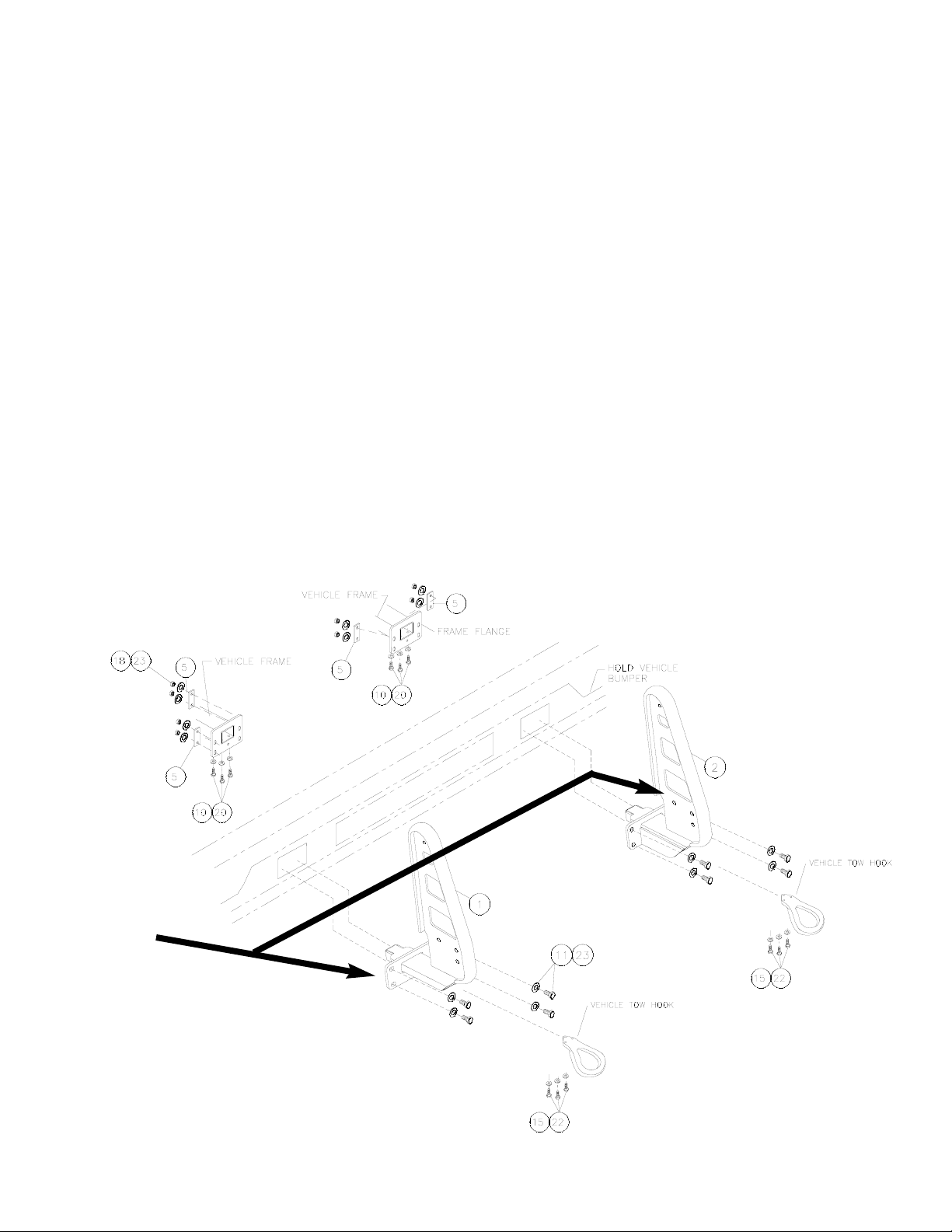
DO NOT FULLY TIGHTEN HARDWARE UNTIL LATER!
5. Remove vehicle tow hooks. Discard existing hardware.
6. Remove L.H. vehicle bumper bracket bolts (2 bolts).
Secure L.H. mounting arm to vehicle frame using (1) nutplate (item #5), (2) 1/2-13NC x 1.75 capscrews (item
#11), (2) lockwashers (item #22), (2) flatwashers (item
#23), and (2) nuts (item #18). The nutplates go to the
backside of the frame flange. NOTE: The other pair of nutplates are installed at the end of the installation (see step
17).
Hint: To align holes between mounting bracket, bumper
bracket, and frame, you may need to raise or lower the
bumper slightly.
7. Install (3) 1/2-13NC x 1.50 capscrews (item #10) and
(3) lockwashers (item #22) through underside of vehicle
frame and into nutplate (item# 4).
8. Repeat for R.H. mounting arm.
9. Install tow hooks into the ends of the R.H. and L.H.
mounting arms using (3 per side) M12 x 1.75 x 30mm
capscrews (Item #15) and 1/2” lockwashers (Item #22).
Install tow hooks pointing downward.
3
Outside mounting
holes in brackets
are slotted
Page 4

4
NOTE: For the following step, you will require assistance.
10. Place mounting channel (Item #6) between mounting
arm assemblies (items #1 and #2). Use (3 each side)
1/2-13NC x 1.5 capscrews (Item #10), lockwashers
(Item #22), and nuts (Item #18) to attach channel to
mounting arm assemblies.
11. Install grille tube (Item #7) between the mounting arms,
placing shims (Item #26) between mounting arms and
ends of tube. Use (2) 3/8-16NC X 1.0 capscrews (Item
#9).
12. Align channel and mounting arms and tighten front hardware to proper torque values before tightening back hardware (see Torque Value Chart).
FOR WRAP AROUND KIT (P/N 295373) ONLY:
13. Attach Light Tube Assemblies (item #28) to R.H. and
L.H. Mounting Arms using (2 each side) 3/8 Carriage
Bolts (item #29), flat washers (item #31), lockwashers
(item #32), and nuts (item #30). Tighten snugly.
14. Install the fairlead (supplied with winch) to the channel by
pushing (2) 3/8-16NC capscrews (supplied with winch)
with lockwasher (item #19) through fairlead and into
captive nuts in channel. The fairlead should be rotated so
that the smaller set of holes are down as shown below.
Insert the capscrews through the smaller set of holes in
the fairlead. Tighten to 34 ft-lbs. torque.
15. If needed, install the license plate brackets (item #3) to
the underside of the channel using (2) 1/4 self-tapping
screws (item #16) and (2) lockwashers (item #21).
Attach license plate to brackets using (4) 1/4-20NC x .5
screws (item #8), (4) lockwashers (item #21) and (4)
nuts (item #17).
MOUNT FAIRLEAD WITH SMALLER
(7/16") HOLES DOWN AND CHAMFER
AT LOWER LEFT. (FAIRLEAD
SUPPLIED WITH WINCH)
Page 5

16. Drill (2 each side) 9/16” holes through bumper
bracket using mounting arm flanges’ inside holes as
guides.
17. Using (2 each side) 1/2-13NC X 1.75 capscrews
(Item #11), (2 each side) lockwashers (Item #22),
(1 each side) nutplate (Item #5), (2 each side) flat
washers (item #23) and (2 each side) nuts (Item
#18), bolt mounting arm and bumper bracket to
vehicle frame.
18. Tighten all remaining bolts to proper torque values
(see Torque chart below).
19. Refer to Winch Owner’s Manual for instructions on
electrical connections. Be sure battery cables are
not drawn taut across any surfaces which could
possibly damage them.
20. Push battery cable into loom (Item #27) and slide
loom up cables as close as possible to mounting
frame assembly. Secure using cable ties (Item #24)
at each end of loom. To improve appearance, wrap
ends of loom with electrical tape.
21. Plug remote switch into receptacle on top of solenoid. Run winch forward and reverse to check connections. Snap appropriate “IN” and “OUT” disk into
proper thumb cavity, after determining winch operating direction. Do not leave switch plugged in when
winch is not in use.
22. Install wire rope according to instructions in the
Winch Owner’s Manual.
5
Bolt Torque, Torque,
Size ft-lbs. Nm
1/4-20 5 ft-lbs 7 Nm
3/8-16 34 ft-lbs 46 Nm
1/2-13 87 ft-lbs 118 Nm
12 mm 39 ft-lbs. 53 Nm
T
orque Value Chart
Page 6

6
Page 7

7
4
6
5
29
14
19
23
16
22
10
9
8
17
30
5
1
2
7
27
24
26
3
15
21
25
28
11
12
13
18
20
31
Page 8

295372 RE GRILLE GUARD PARTS LIST
ITEM
NO.
PART
NO.
QTY. DESCRIPTION
1 265100 1 RH MOUNTING ARM ASSY
2 265101 1 LH MOUNTING ARM ASSY
3 312525 2 LICENSE PLATE BRACKET
4 350666 2 NUT PLATE (5 HOLES)
5 364165 4 NUT PLATE (2 HOLES)
6 395230 1 MOUNTING CHANNEL
7 395421 1 GRILLE TUBE
8 414036 4 CAPSCREW 1/4-20NC X .5 HX HD GR5 BLK
9 414321 5 CAPSCREW 3/8-16NC X 1 HX HD GR5 BLK
10 414551 12 CAPSCREW 1/2-13NC X 1.5 HX HD GR5 BLK
11 414556 8 CAPSCREW 1/2-13NC X 1.75 HX HD GR5 BLK
12 414592 4 CAPSCREW 1/2-13NC X 1.25 HX HD GR5 BLK
13 414919 3 CAPSCREW 3/8-16NC X 1 SOC HD GR5 BLK
14 414936 2 CAPSCREW 3/8-16NC X .75 SOC HD GR5 BLK
15 415316 6 CAPSCREW M12 X 1.75 X 30mm HX HD Z/P
16 416279 2 SCREW 1/4-20NC X .75 SELF-TAP HX BLK
17 418020 4 HEX NUT 1/4-20NC BLK
18 418072 10 HEX NUT 1/2-13NC BLK
19 418175 5 LOCKWASHER 3/8 BLK
20 418188 5 LOCKWASHER 3/8 HI-COLLAR BLK
21 418147 6 LOCKWASHER 1/4 BLK
22 418216 30 LOCKWASHER 1/2 BLK
23 418229 12 FLAT WASHER 1/2 BLK
24 440138 4 CABLE TIES
25 472027 2 PLUG
26 488011 2 SHIMS
27 690504 1 LOOM
295373 WRAPAROUND KIT ADDITIONAL PARTS
28 395386 2 LIGHT TUBE ASSY
29 414220 4 CARRIAGE BOLT 3/8-16NC X 1 BLK
30 418033 4 HEX NUT 3/8 BLK (SAME AS #17)
31 418174 4 FLAT WASHER 3/8 BLK
32 418175 4 LOCKWASHER 3/8 BLK (SAME AS #19)
 Loading...