

Page 1

INSTALLATION INSTRUCTIONS
FOR RE GRILLE GUARD KIT # 295370
ON 2003-2007 DODGE RAM HD 2500/3500 4X4 2X4
Notice
Ramsey kits are designed for use with Ramsey Winches only.
Use or sale of kits for other winches or applications voids warranty.
Warning
Ramsey offers mounting kits and winches for various vehicles. In crash tests on a limited number of automotive
manufacturer’s vehicles, winches/mounting kits, which have been properly mounted, have not interfered with air bag
operation.
The user/customer, or their installer, must verify that the mounting kit does not interfere with the factory air bag sensors, which must not be relocated or modified in any way.
The user/customer should follow the vehicle manufacturer’s recommendations and those of a qualified mechanic to
determine if the winching/mounting kit might interfere with the air bag operation. The user/customer should then
determine the suitability of a winch/mounting kit on a particular vehicle.
PLEASE BE ADVISED THAT THE VEHICLE’S AIR BAG SYSTEM MAY NOT OPERATE PROPERLY IF THE
WINCH/MOUNTING KIT IS NOT MOUNTED IN COMPLIANCE WITH THE VEHICLE MANUFACTURER’S RECOMMENDATIONS.
DO NOT ATTACH TOW HOOK TO ANY PART OF MOUNTING KIT UNLESS INSTRUCTED TO DO SO.
DO NOT SUBSTITUTE ATTACHING HARDWARE ITEMS (BOLTS, NUTS, OR WASHERS).
READ AND UNDERSTAND WINCH OWNER’S MANUAL BEFORE INSTALLATION AND OPERATION OF THE WINCH.
SEE WARNINGS AND CAUTIONS IN WINCH OWNER’S MANUAL.
IMPORTANT NOTES!
1. RIGHT AND LEFT HAND DIRECTIONS AS IF SEATED BEHIND STEERING WHEEL.
2. ALL FASTENING HARDWARE MUST BE LOOSELY ASSEMBLED UNTIL DIRECTED TO TIGHTEN.
RAMSEY WINCH COMPANY
P.O. BOX 581510
TULSA, OKLAHOMA 74158
PHONE: (918) 438-2760 • FAX: (918) 438-6888
http://www.ramsey.com
913392-0607-D
Page 2
Note: If the vehicle is equipped with a
diesel engine, raise hood and remove (2)
bolts on the oil cooler. It will be necessary to
lift cooler to allow access to frame and bumper
bolts in the next steps.
If vehicle is not diesel, proceed to step #1.
Note: It is not necessary to remove the airdam in order to modify it or
install the kit.
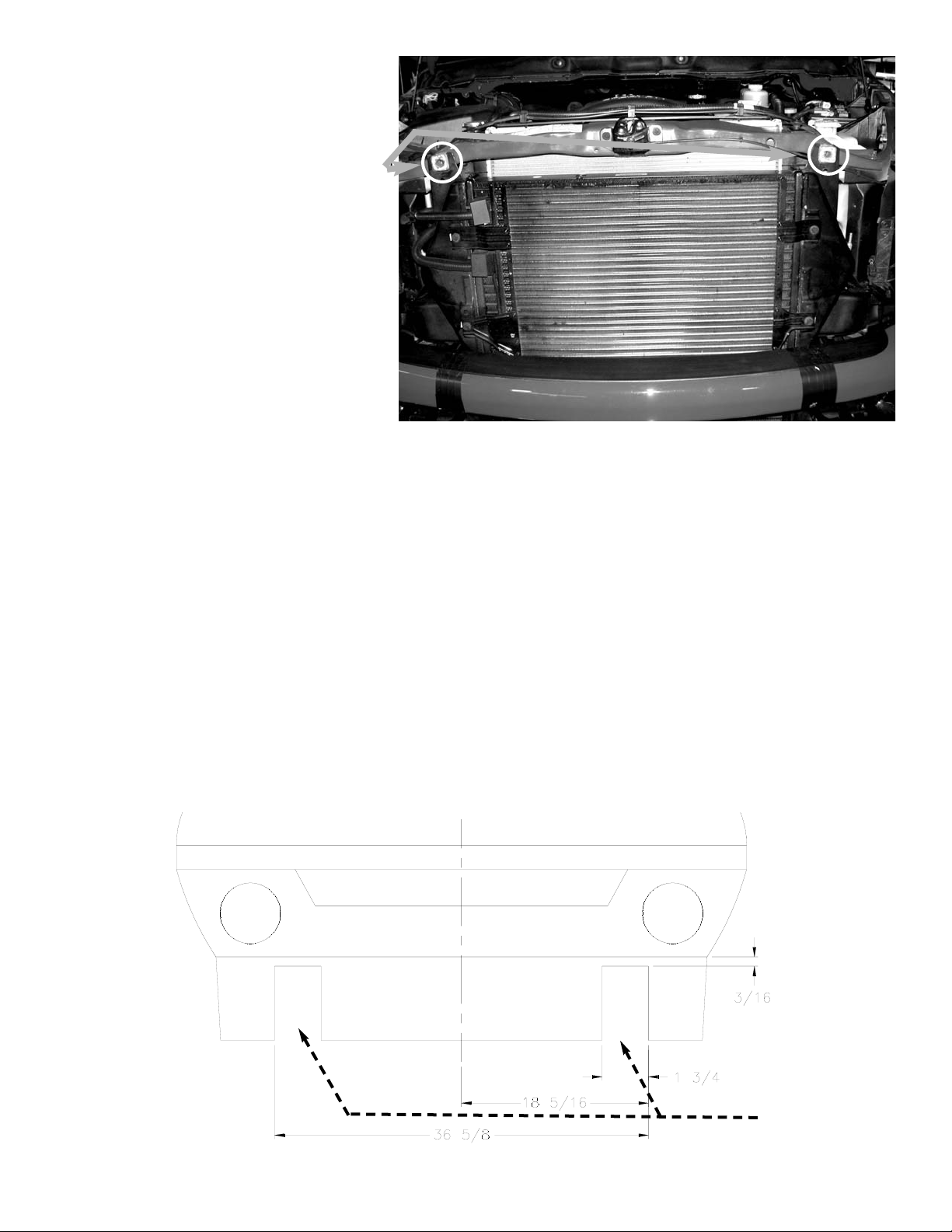
1. Cut notches in air dam for the Mounting Arms to fit through. Cut 1 3/4” wide
notches from the bottom of the air dam, cutting through the bottom lip of the
air dam. Cut the notches to within 3/16” of the top of the air dam. Do not cut
all the way through the air dam. As shown below, the spacing of the notches
is 18 5/16” from center to outside of notch. One of the clips that holds the air
dam to the bumper should be at the center of the air dam, use it to measure.
The 1 3/4” width of the notch does not allow any clearance of the arm that
fits through it. You may need to trim it slightly after you have the arm
installed, but you will want the fit as tight as possible.
2
Air dam
Cut Notches
Here
Bumper
Page 3
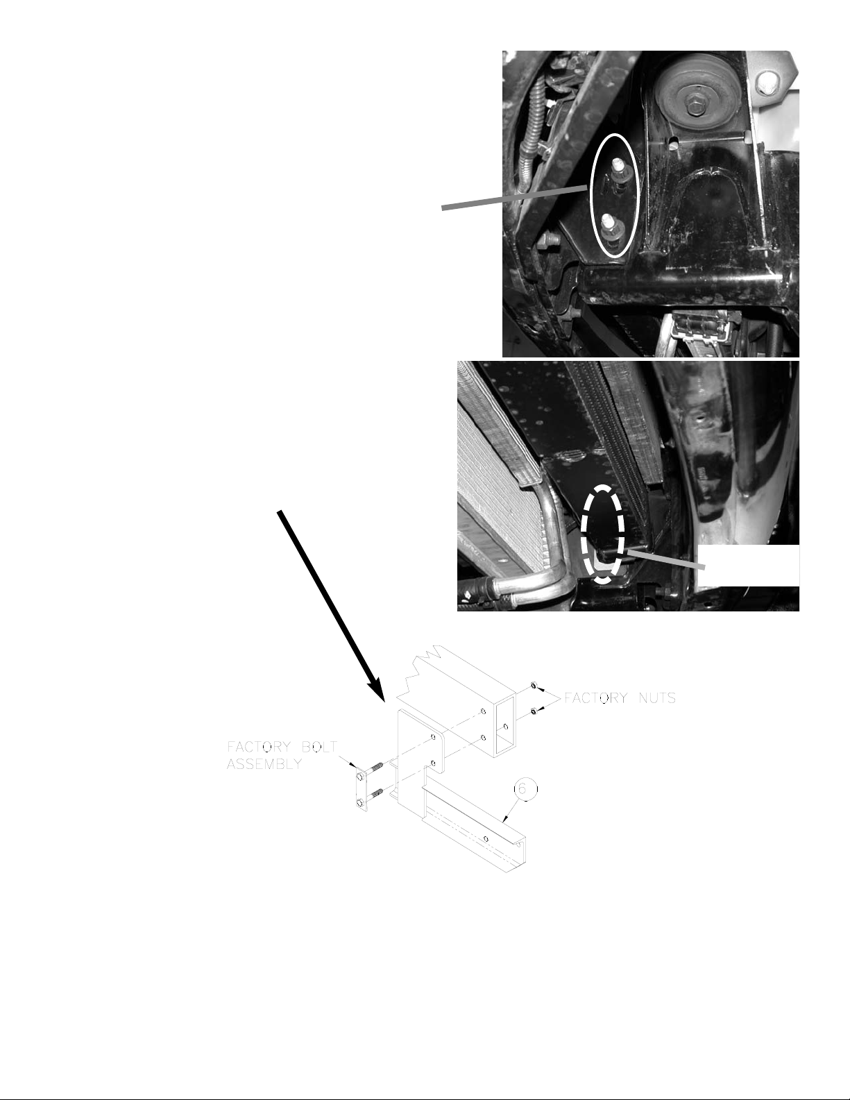
It is a good idea to install the mounting bracket assembly
entirely on one side, then start on the other. Install bolts
loosely—do not tighten until told to do so.
2. Loosen and remove factory bolt assembly nuts. Figure at
right is view from under vehicle looking up at frame. The
bolt assembly points away from vehicle frame.
3. If vehicle is diesel, push oil cooler up to access factory
bolt assembly (see figure at right).
Remove factory bolt assembly and install bolt assembly
through mounting arm (item #6) then vehicle frame.
Tighten nuts on bolt assembly according to Torque Value
Chart on page 6.
Repeat for the left side.
Bumper
Oil Cooler
Factory Bolt
Assembly
3
Page 4

4. Place winch in Frame Assembly (item #4) and install using
hardware as shown at right. Install (3) 3/8-16NC 1” long
socket head capscrews (item #12) and high collar lockwashers (item #19) in the front, right three mounting holes.
Install (2) 3/8-16NC 3/4” long socket head capscrews (item
#13) and high collar lockwashers (item #19) in the front and
back left mounting holes.
Install (3) 3/8-16NC 1” long hex head capscrews (item #9)
and regular lockwashers (item #18) in the rear, left three
mounting holes.
Do not tighten until told to do so.
Assistance is required for the next steps.
5. Attach the right and left side plates
(item #1) to the winch frame using (3)
1/2-13NC x 1-3/4” capscrews (item
#11), nuts (item #16) and lockwashers (item #20).
Do not tighten until told to do so.
6. Lift the winch and side plate assembly into place on the right and
left mounting arms (items #6 and7). Install the side plates (item
#1) into the mounting arms using (3) 1/2-13NC x 1-3/4” capscrews (item #11), nuts (item #16), and lockwashers (item
#20).
Do not tighten until told to do so.
4
Page 5

7. Install grille tubes (item #5) to right and left hand side
plates as shown at right. Use (2) 3/8-16NC capscrews
(item #9) and shims (item #22) for each tube.
Do not tighten until told to do so.
8. Install the fairlead using 3/8-16NC hardware supplied with
the winch as shown at right.
Do not tighten until told to do so.
9. If needed, install the license tag brackets (item #3) to the
underside of the winch frame as shown at right using (2)
1/4-20NC self-tapping screws. These screws go into holes
on the left side of the underside of the winch frame.
Tighten to 5 ft-lbs (7 Nm) torque.
Install the license plate to the brackets using (4) 1/4-20NC
capscrews (item 8), nuts (item #15), and lockwashers
(item #17).
5
Page 6

10. Align the mounting kit and tighten all screws to the values
listed in the Torque Value Chart at right. Work from the
bottom of the mounting kit up.
11. Once the mounting kit is tightened up, place the
mounting angle (item 2) between the mounting arm
(item #7) and the vehicle frame. The mounting angle
needs to be snug against both. Clamp the mounting
angle and mounting arm together, and mark drill hole
locations on the mounting angle (see figure above).
Drill 0.515” thru holes at the marked locations.
Install the mounting angle to the mounting arm using
(2) 1/2-13NC capscrews (item #10), nuts (item
#16), and lockwashers (item #20). Tighten according
to Torque Value Chart above.
Repeat for other side.
12. Refer to Winch Owner’s Manual for instructions on
electrical connections. Be sure battery cables are not
drawn taut across any surfaces that could damage
them.
13. Push battery cables into loom (item #23) and slide loom
up cables as close as possible to mounting frame assembly. Secure using cable ties at each end of loom. To
improve appearance, wrap ends of loom with electrical
tape.
14. Plug remote switch into female receptacle and confirm
that winch operates. Install cable according to instructions
in Owner’s Manual.
6
Bolt Torque, Torque,
Size ft-lbs. Nm
1/4-20 5 ft-lbs 7 Nm
3/8-16 34 ft-lbs 46 Nm
1/2-13 87 ft-lbs 118 Nm
12mm (factory) 39 ft-lbs 54 Nm
Torque Value Chart
Mounting
Arm
Frame
Mounting
Angle
Page 7

7
Page 8

Item No. Part No. Qty. Description
1 265095 2 LH & RH SIDE PLATE
2 303100 2 MOUNTING ANGLE
3 312525 2 LICENSE TAG BRACKET
4 395230 1 WINCH FRAME ASSEMBLY
5 395421 2 GRILLE TUBE
6 408332 1 RH MOUNTING ARM
7 408333 1 LH MOUNTING ARM
8 414036 4 CAPSCREW 1/4-20NC X 1/2 HX HD GR5 F/B
9 414321 7 CAPSCREW 3/8-16NC X 1 HX HD GR5 F/B
10 414551 4 CAPSCREW 1/2-13NC X 1-1/2 HX HD GR5 F/B
11 414609 12 CAPSCREW 1/2-13NC X 1-3/4 HX HD GR8 F/B
12 414919 3 SCREW 3/8-16NC X 1 HX SOC HD F/B
13 414936 2 CAPSCREW 3/8-16NC X 3/4 HX SOC HD F/B
14 416279 2 SCREW 1/4-20 X 3/4 HX HD SELF-TAP F/B
15 418020 4 NUT 1/4-20NC HEX REG F/B
16 418072 16 NUT 1/2-13NC HEX REG F/B
17 418147 4 LOCKWASHER 1/4 F/B
18 418175 3 LOCKWASHER 3/8 F/B
19 418188 5 LOCKWASHER 3/8 HI-COLLAR F/B
20 418216 16 LOCKWASHER 1/2 F/B
21 472027 2 PLUG - BLACK PLASTIC (NOT PICTURED)
22 488011 4 SHIM
23 690504 24” LOOM (NOT PICTURED)
8
Parts List
2
7
6
2
5
22
5
1
1
3
8
14
13
12 9
10
11
15
17
18
19
16
20
4
 Loading...