

Page 1
INSTALLATION INSTRUCTIONS
FOR GRILLE GUARD KIT #295369 (PATRIOT 12/15 WINCHES)
ON ALL 2003-2007* CHEVY AVALANCHE 2500
2003-2007* CHEVY SILVERADO/GMC SIERRA
1500 HD / 2500 / 2500 HD / 3500
Notice
Ramsey kits are designed for use with Ramsey Winches only.
Use or sale of kits for other winches or applications voids warranty.
Warning
Ramsey offers mounting kits and winches for various vehicles. In crash tests on a limited number of automotive
manufacturer’s vehicles, winches/mounting kits, which have been properly mounted, have not interfered with air bag
operation.
The user/customer, or their installer, must verify that the mounting kit does not interfere with the factory air bag sensors, which must not be relocated or modified in any way.
The user/customer should follow the vehicle manufacturer’s recommendations and those of a qualified mechanic to
determine if the winching/mounting kit might interfere with the air bag operation. The user/customer should then
determine the suitability of a winch/mounting kit on a particular vehicle.
PLEASE BE ADVISED THAT THE VEHICLE’S AIR BAG SYSTEM MAY NOT OPERATE PROPERLY IF THE
WINCH/MOUNTING KIT IS NOT MOUNTED IN COMPLIANCE WITH THE VEHICLE MANUFACTURER’S RECOMMENDATIONS.
DO NOT ATTACH TOW HOOK TO ANY PART OF MOUNTING KIT UNLESS INSTRUCTED TO DO SO.
DO NOT SUBSTITUTE ATTACHING HARDWARE ITEMS (BOLTS, NUTS, OR WASHERS).
READ AND UNDERSTAND WINCH OWNER’S MANUAL BEFORE INSTALLATION AND OPERATION OF THE WINCH.
SEE WARNINGS AND CAUTIONS IN WINCH OWNER’S MANUAL.
IMPORTANT NOTES!
1. RIGHT AND LEFT HAND DIRECTIONS AS IF SEATED BEHIND STEERING WHEEL.
2. ALL FASTENING HARDWARE MUST BE LOOSELY ASSEMBLED UNTIL DIRECTED TO TIGHTEN.
RAMSEY WINCH COMPANY
P.O. BOX 581510
TULSA, OKLAHOMA 74158
PHONE: (918) 438-2760 • FAX: (918) 438-6888
http://www.ramsey.com
913382-0307-D
* 2007 Classic series
Page 2
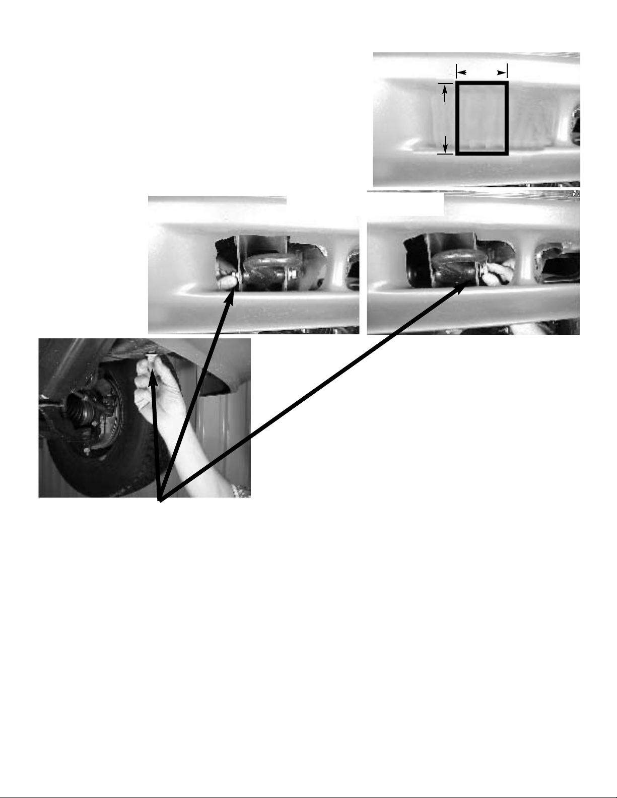
1. Remove the three M12 bolts that secure the vehicle tow
hooks. They are located on either side and on the bottom of the frame (See figures above).
2. Remove the tow hook and the factory hardware and set
it aside.
2
Note: It is not necessary to remove the vehicle bumper to install
this mounting kit.
Note: In two-wheel drive models that do not have front tow hooks, it
will be necessary to cut through bumper for access to frame. From the
underside of the vehicle, mark a starting point from a corner of the end
of the frame. Make a rectangular cut 3.25” wide from the top of the
pocket to the bottom (approximately 3-3.25” high, as shown at right).
The cut does not have to be exact, as the hole will be covered by the
grille guard.
3.25”
~3-
3.25”
CUTOUT FOR TWO-WHEEL DRIVE MODELS
FOUR-WHEEL DRIVE MODELS
(NO CUTOUT REQUIRED)
Page 3
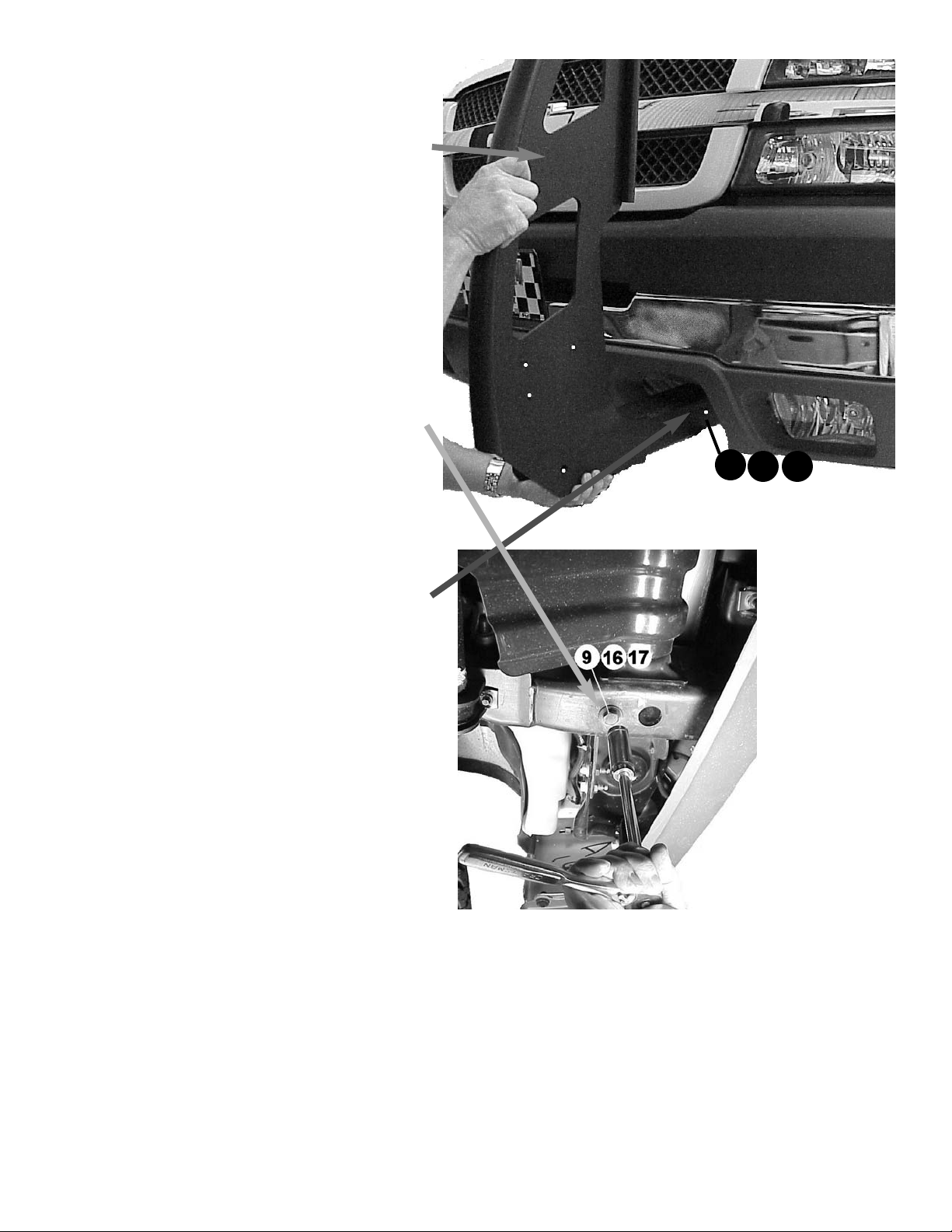
3. Install left mounting arm (Item #2) by inser ting it
through the existing tow hook access in the air
dam. The mounting arms should be installed so
that the side plates are on the outside.
4. Install 1/2-13NC X 1-1/4” zinc plate capscrew
(Item #9), lockwasher (Item #16), & flat washer
(Item #17) through bottom hole in frame and into
captive nut in arm. Figure below shows underside
of frame and bracket.
Note: Both zinc plate and black finish 1/2-13NC x
1-1/4” capscrews are supplied in kit. Use zinc
plate in this step, and black finish in step #8.
5. Install 1/2-13NC X 4.5” hex head bolt (Item #7)
through hole in frame (this is where the tow hook
was unbolted in step 1) and through arm #2.
Secure using lockwasher (Item #16) & nut (Item
#13).
6. Install right hand arm following steps 1 through 5 on
right hand side. Do not tighten bolts until winch mounting channel and grille tubes are installed.
7
13 16
3
Page 4

7. Place vehicle tow hooks into the front section of left hand and
right hand mounting arms and secure using existing tow hook
mounting hardware removed in step 1 at sides and bottom of
tow hook.
8. Have someone hold the mounting channel (Item
#1) between the left and right mounting arms (Item
#2 and #3). Insert (3) 1/2-13NC x 1-1/4” black
finish capscrews (Item #8) through mounting arm
(Item #2), and mounting channel (Item #1).
Secure using (3) lockwashers (Item #16) and (3)
nuts (Item #13) loosely.
Note: Silver finish capscrew shown in figure at right for
visibility in picture. Make sure to use black finish capscrews.
9. Position right side and secure the same way.
4
1
2
8
13 16
16
13
8
3
2
1
5
Page 5

10. Install grille tube (Item #5) between mounting arms
(Item #2 and #3). Insert (1 each side) shim (Item
#19) between tube and mounting arm at each end.
Secure using (1 each side) 3/8-16NC X .75 long
capscrew (Item #11) through mounting arm and
into threaded hole in each end of tube.
11. TIGHTEN ALL HARDWARE COMPLETELY. Start at
the grille tube and work down to the mounting channel tightening all hardware to the appropriate torque
value. (See Torque Value Chart).
12. If needed, install License Tag Bracket
(Item #4) to underside of winch channel (Item #1) using (2) 1/4-20NC X
1” capscrews (Item #10), (2) 1/4
nuts (Item #12), and (2) 1/4 lock
washers (Item #14). Refer to drawing
at right.
13. Install license tag to License Tag
Bracket using (2) 1/4-20NC X 1/2
capscrews (Item #6). Using (2) 1/4
flat washers (Item #15) if needed for
spacing.
14. Install fairlead using hardware furnished with winch. As shown at right,
note that the mounting bolts should go
through the winch channel and 1/2” holes (turn fairlead so that these holes are on top) in roller fairlead.
15. Lift the winch into the winch channel (Item #1).
16. Using hardware supplied with the winch, install four
bolts through bottom of channel and into feet of
winch.
5
11
5
19
2
View from Underside
of Winch Channel
4
10
12 14
6 15
Tip: To orient fairlead,
make sure chamfered
edge is at lower left.
Install bolts through slot in
winch channel, and upper
(1/2”) bolt hole in fairlead.
Page 6

17. Refer to Winch Owner’s Manual for instructions on
electrical connections. Be sure battery cables are
not drawn taut across any surfaces which could
possibly damage them.
Hint: Lift vehicle hood and remove plastic
shroud to get easy access to area between
grille and radiator to install cables.
18. Push battery cable into loom (Item #20) and slide
loom up cables as close as possible to mounting
frame assembly. Secure using cable ties (item #18)
at each end of loom. To improve appearance, wrap
ends of loom with electrical tape.
19. Plug remote switch into receptacle on top of solenoid. Run winch forward and reverse to check connections. Snap appropriate “IN” and “OUT” disk into
proper thumb cavity, after determining winch operating direction. Do not leave switch plugged in when
winch is not in use.
20. Place end of wire rope through fairlead and attach
clevis hook. Use clevis pin and cotter pin (furnished
with winch).
21. Tighten all bolts to proper torque values (see Torque
Value chart).
6
Bolt Torque, Torque,
Size ft-lbs. Nm
1/4-20 5 ft-lbs 7 Nm
3/8-16 34 ft-lbs 46 Nm
1/2-13 87 ft-lbs 118 Nm
T
orque Value Chart
Page 7

7
Finished Assembly on Truck
Page 8

8
1
2
3
20
17
16
13
7
9
8
11
19
5
18
10
4
6
15
14 12
ITEM NO. PART NO. QTY DESCRIPTION
1 408320 1 WINCH MOUNTING CHANNEL
2 265092 1 LH MOUNTING ARM ASSEMBLY
3 265093 1 RH MOUNTING ARM ASSEMBLY
4 204260 1 LICENSE TAG BRACKET
5 395421 1 GRILLE TUBE
6 414036 2 CAPSCREW, 1/4-20NC X 1/2 LG HX HD GR5 F/B
7 414519 2 CAPSCREW, 1/2-13NC X 4 1/2 LG HX HD GR5 Z/P
8 414592 6 CAPSCREW, 1/2-13NC X 1 1/4 LG HX HD GR5 F/B
9 414578 2 CAPSCREW, 1/2-13NC X 1 1/4 LG HX HD GR5 Z/P
10 414829 2 CA PS CREW , 1/4-20 NC X 1 SOCKET BUTTON HD F/B
11 414321 2 CA PS CREW , 3/8-16NC X 1 LG HX HD F/B
12 418020 2 NUT, 1/4-20NC HEX REG F/B
13 418072 8 NUT, 1/2-13NC HEX REG F/B
14 418147 4 LOCKWA SHER, 1/4 MED SECTION F/B
15 418158 2 W ASHER, 1/ 4 FLAT SAE F/B
16 418216 10 LOCKW ASHER, 1/2 MED SECTION F/B
17 418223 2 W ASHER, 1/ 2 USS FLAT Z/P
18 440138 4 CABLE TIE
19 488011 2 S HIM
20 690504 1 LOOM, W IRE 24"
PARTS LIST FOR KIT #295369
 Loading...