

Page 1

INSTALLATION INSTRUCTIONS
FOR GRILLE GUARD KIT #295368
ON 1999-2004 FORD EXCURSION / SUPER-DUTY TRUCKS
Notice
Ramsey kits are designed for use with Ramsey Winches only.
Use or sale of kits for other winches or applications voids warranty.
Warning
Ramsey offers mounting kits and winches for various vehicles. In crash tests on a limited number of automotive
manufacturer’s vehicles, winches/mounting kits, which have been properly mounted, have not interfered with air bag
operation.
The user/customer, or their installer, must verify that the mounting kit does not interfere with the factory air bag sensors, which must not be relocated or modified in any way.
The user/customer should follow the vehicle manufacturer’s recommendations and those of a qualified mechanic to
determine if the winching/mounting kit might interfere with the air bag operation. The user/customer should then
determine the suitability of a winch/mounting kit on a particular vehicle.
PLEASE BE ADVISED THAT THE VEHICLE’S AIR BAG SYSTEM MAY NOT OPERATE PROPERLY IF THE
WINCH/MOUNTING KIT IS NOT MOUNTED IN COMPLIANCE WITH THE VEHICLE MANUFACTURER’S RECOMMENDATIONS.
DO NOT ATTACH TOW HOOK TO ANY PART OF MOUNTING KIT UNLESS INSTRUCTED TO DO SO.
DO NOT SUBSTITUTE ATTACHING HARDWARE ITEMS (BOLTS, NUTS, OR WASHERS).
READ AND UNDERSTAND WINCH OWNER’S MANUAL BEFORE INSTALLATION AND OPERATION OF THE WINCH.
SEE WARNINGS AND CAUTIONS IN WINCH OWNER’S MANUAL.
IMPORTANT NOTES!
1. RIGHT AND LEFT HAND DIRECTIONS AS IF SEATED BEHIND STEERING WHEEL.
2. ALL FASTENING HARDWARE MUST BE LOOSELY ASSEMBLED UNTIL DIRECTED TO TIGHTEN.
RAMSEY WINCH COMPANY
P.O. BOX 581510
TULSA, OKLAHOMA 74158
PHONE: (918) 438-2760 • FAX: (918) 438-6888
http://www.ramsey.com
913381-0704-F
Page 2
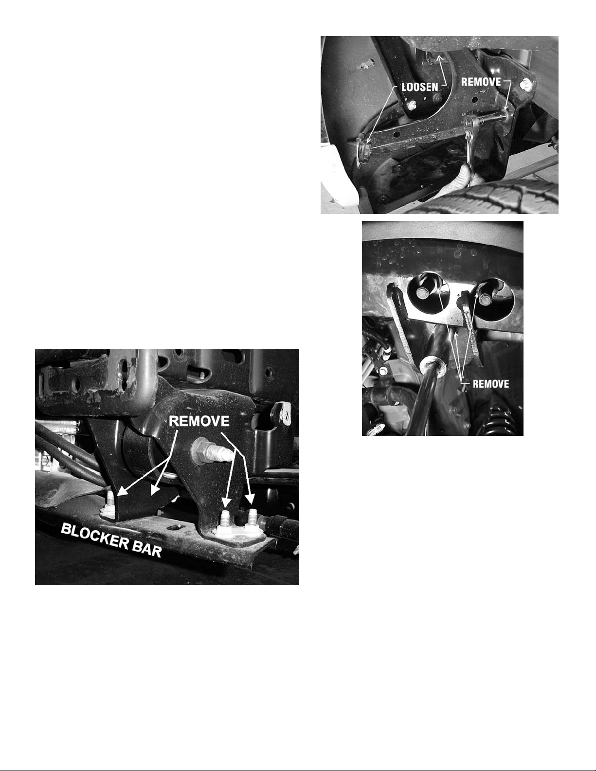
1. Unfasten plastic splashguard from radiator support bracket. Loosen, but do not remove, the two bolts on the arms
of the bumper support bracket as shown at top right.
2. Remove the bolt attached to the vehicle frame. Repeat for
other side of vehicle.
3. Remove the three nuts on the underside of the blocker bar
as shown at middle right. Remove blocker bar.
On some models, to remove the blocker bar, remove the
four bolts that hold the blocker bar to the bracket as
shown below.
4. Note: On diesel models, disconnect engine heater plug
from back side of bumper. Models with Fog lights, unplug
lights and pull harness loose from back side of bumper.
5. Remove vehicle bumper and tow hooks.
2
Page 3
6. As shown at right, if the truck is equipped with fog
lights, remove clip for fog light electrical harness
from inside of frame. Tie off fog light electrical harness further back.
7. Remove factory bolt and nut from frame and install
(1 per side) 7/16-14NC X 1-1/2” capscrew (Item
#11), 7/16 nut (Item 14), and lockwasher (Item
#16) with bolt reversed in frame (so that bolt is
pointing outward). Repeat for other side.
NOTE: Some models may not have these factory
bolts. If there is no factory bolt, skip this step.
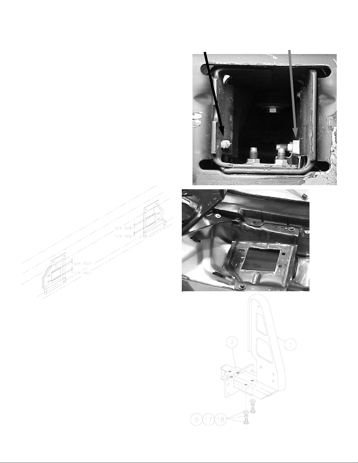
8. Enlarge rectangular cutout in bumper bracket by 3/4”
at top and 1/4” at bottom as shown below. The finished bracket will appear as shown middle right.
9. Remove air dam.
10. Attach (1 each side) nut plate (Item #3) loosely to
inside of each Mounting Bracket Assembly (Items
#1 and #2) using (2 each side) 1/2-13NC X 1-1/4
capscrews (Item #9), (2 each side) washers (Item
#18), and (2 each side) lockwashers (Item #17) on
each assembly. See illustration at right.
3
REMOVE CLIP FOR
FOG LIGHT ELECTRICAL HARNESS
REMOVE FACTORY BOLT
AND NUT. REPLACE
WITH SUPPLIED BOLT
AND NUT, REVERSED.
Page 4

Note: Installation of the mounting brackets
must be done simultaneously with installing
the bumper on the vehicle. You will need
assistance for this step.
11. Lift bumper into place. While holding bumper in
place, install end of R.H. and L.H. mounting brackets
through bumper and bumper brackets and into vehicle frame. Make sure mounting brackets are
positioned so that slotted holes in flanges are
to the outside.
12. Secure R.H. and L.H. mounting brackets to vehicle
frame using (1 each side) nutplate (Item #4), (2
each side) 1/2-13NC x 1-3/4 capscrews (Item #7),
(2 each side) lockwashers (Item #17), and nuts
(Item #13) on each side. These nutplates go to the
outside of the frame. The other pair of nutplates are
installed at the end of the installation (see step 25).
13. Install (3 each side) 1/2-13NC x 1-1/2 capscrews
(Item #8) and (3 each side) lockwashers (Item
#17) through underside of vehicle frame and into
nutplate (Item #3).
14. Install tow hooks using (3 per side) M12x1.75x
50mm capscrews (Item #12) and 1/2” lockwashers
(Item #17) to the R.H. and L.H. mounting brackets.
4
Outside mounting
holes in brackets
are slotted
Page 5

15. Place Channel Assembly (Item #6) between mounting bracket assemblies. Use (3 each side) 1/2-13NC
x 1-1/4 capscrews (Item #9), lockwashers (Item
#17), and nuts (Item #13) to attach side plates and
channel to mounting bracket assembly.
5
Page 6

16. Install Grille Tube (Item #5) between the mounting
brackets, placing shims (Item #20) between mounting brackets and ends of tube. Use (2) 3/8-16NC X
3/4 capscrews (Item #10) and lockwashers (Item
#15).
17. Align channel and mounting brackets and
tighten front hardware to proper torque values before tightening back hardware (see
Torque Value Chart).
18. Mount fairlead to channel assembly using
hardware supplied with winch. Bolts should
go through upper holes on fairlead. Tighten
fairlead mounting bolts to 34 ft. lbs (46 Nm)
torque.
19. Place winch in Channel Assembly (Item
#6). Use supplied mounting hardware to
attach winch to Channel Assembly. Refer to
Winch manual for mounting instructions.
Tighten winch mounting bolts to 55 ft. lbs.
(75 Nm) torque.
6
Zinc finish capscrews and
nuts used for clarity. Kit contains black finish hardware.
Page 7

20. Reinstall air dam.
21. Reinstall engine heater plug (if diesel model).
22. Reinstall splash guard.
23. Reinstall blocker bar.
24. Drill (2 each side) 9/16” holes through bumper
bracket using mounting bracket flange inside holes
as guides.
25. Using (2 each side) 1/2-13NC X 1-3/4 capscrews
(Item #7), (2 each side) lockwashers (Item #17), (1
each side) nutplate (Item #4), and 1/2” nut (Item
#13), bolt mounting bracket and bumper bracket to
vehicle frame.
26. Refer to Winch Owner’s Manual for instructions on
electrical connections. Be sure battery cables are
not drawn taut across any surfaces which could
possibly damage them.
27. Push battery cable into loom (Item #21) and slide
loom up cables as close as possible to mounting
frame assembly. Secure using cable ties (Item #19)
at each end of loom. To improve appearance, wrap
ends of loom with electrical tape.
28. Plug remote switch into receptacle on top of solenoid. Run winch forward and reverse to check connections. Snap appropriate “IN” and “OUT” disk into
proper thumb cavity, after determining winch operating direction. Do not leave switch plugged in when
winch is not in use.
29. Place end of wire rope through fairlead and attach
clevis hook. Use clevis pin and cotter pin (furnished
with winch).
30. Tighten all remaining bolts to proper torque values
(refer to Torque chart below).
7
Bolt Torque, Torque,
Size ft-lbs. Nm
3/8-16 34 ft-lbs 46 Nm
1/2-13 87 ft-lbs 118 Nm
7/16-14 50 ft-lbs 68 Nm
12 mm 39 ft-lbs. 53 Nm
T
orque Value Chart
Page 8

8
Page 9

No. Part No. Qty Description
1 265091 1 LH MOUNTING BRACKET
2 265090 1 RH MOUNTING BRACKET
3 350666 2 NUT PLATE (5 HOLES)
4 364165 4 NUT PLATE (2 HOLES)
5 395421 1 GRILLE TUBE
6 408320 1 CHANNEL
7 414556 8 CAPSCREW 1/2-13NC X 1-3/4
HX HD GR5 BLK
8 414551 6 CAPSCREW 1/2-13NC X 1-1/2
HX HD GR5 BLK
9 414578 10 CAPSCREW 1/2-13NC X 1-1/4
HX HD GR5 Z/P
10 414321 2 CAPSCREW 3/8-16NC X 1
HX HD GR5 FORD BLK
No. Part No. Qty Description
11 414468 2 CAPSCREW 7/16-14NC X 1-1/2
HX HD GR5 Z/P
12 415311 6 CAPSCREW M12 X 1.75 X 50
MM HX HD GR8.8 Z/P
13 418072 14 NUT 1/2-13NC HEX BLK PLTD
14 418049 2 NUT 7/16-14NC HEX Z/P
15 418175 2 LOCKWASHER 3/8 MED BLK
16 418198 2 LOCKWASHER 7/16 MED Z/P
17 418216 30 LOCKWASHER 1/2 MED BLK
18 418221 4 FLATWASHER 1/2 SAE
19 440138 4 CABLE TIES
20 488011 2 PLASTIC SHIMS
21 690504 24” LOOM
9
Parts List
3
6
7
4
18
9
15
14
13
11
10
12
8
16
17
5
1
2
5
21
19
20
 Loading...