

Page 1
Page 2
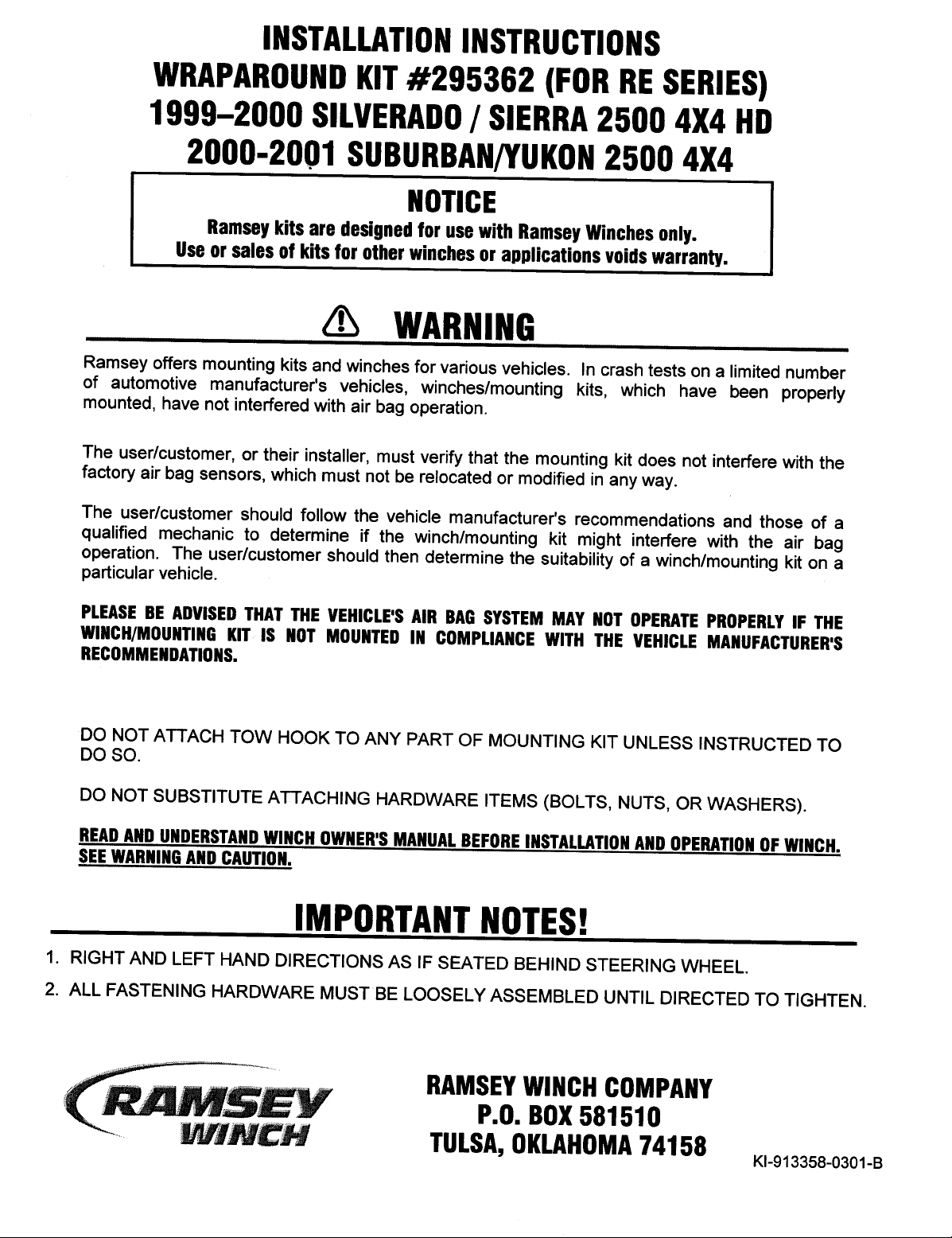
Step 1
Note: It is not necessary to remove or modify the vehicle bumper to install this mounting kit.
Remove the three M12 bolts that secure the vehicle tow hook. They are located on either side and on the bottom of
the tow hook (Figure 1). Remove the tow hook and set it aside.
Figure 1
Step 2
Install left hand bracket #5. Bracket is inserted through the existing
tow hook access in the air dam (Figure 3). Install ½-13 NC x 1-1/4
hex head bolt #12, lockwasher #22, & flat washer #23 through
bottom hole in frame (see Figure 2) and into captive nut in bracket #5.
Step 3
Insert ½-13NC x 4-1/2” hex bolt #10 through hole in frame (this is
where the tow hook was unbolted in step 1) and through bracket
#5 at location shown in Figure 3. Secure using lockwasher #22
& nut #17.
Place vehicle tow hook into the front section of bracket #5 (See
Figure 5), and secure using existing tow hook mounting hardware
removed in step 1 at sides and bottom of tow hook.
1
Figure 2
Figure 3
KI-913358-0200-A
Page 3
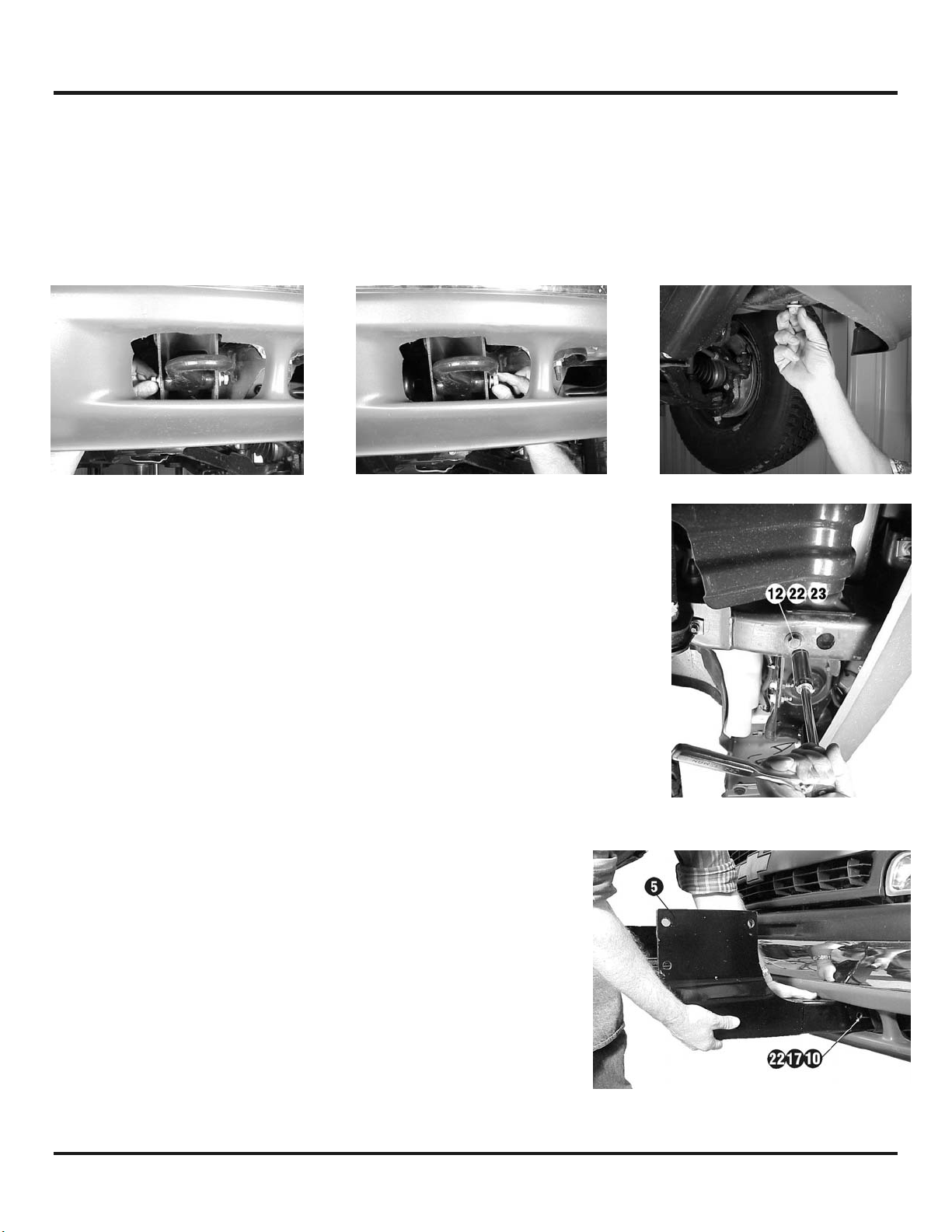
Step 4
Repeat Step 1 through Step 3 for right hand side of vehicle. Tighten hardware to the appropriate
torque value (See Torque Value Chart on page 5).
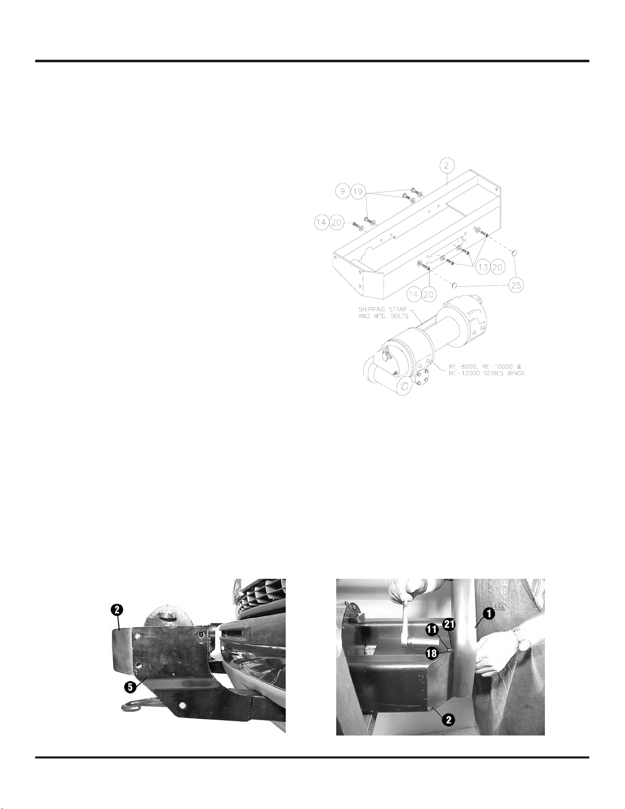
Step 5
Remove shipping strap and mounting bolts from
winch assembly and discard. Place frame assembly
#2 over top of winch and secure. Use (3) 3/8-16NC
x 1” hex head capscrews #9 with lockwashers #19
and (1) 3/8-16NC x ¾” socket head capscrew #14
with 9/16” high collar lockwasher #20 to attach
winch to rear angle of frame assembly (Figure 4). DO
NOT TIGHTEN.
Attach winch to front angle of frame assembly using
(3) 3/8-16NC x 1” socket head capscrews #13 with
high collar lockwashers (9/16 OD) #20 and (1) 3/816NC x ¾” socket head capscrew #14 with 9/16”
high collar lockwasher #20 as shown in Figure 4.
Note: The (2) outer-most capscrews are inserted
through holes in face of mounting frame and threaded
into winch. The (2) inner-most capscrews are placed
through fairlead opening and threaded into winch.
Tighten front hardware to appropriate torque
value, then tighten back hardware (See Torque
Value Chart on page 5). Snap hole plugs #25 into outer-most holes in front of frame assembly.
Figure 4
Step 6
NOTE: YOU WILL NEED ASSISTANCE FOR THIS STEP.
Have someone hold the winch and mounting frame #2 between the left and right brackets. Position
left-hand side plate assembly #1 at the outside of the winch mounting frame (Figure 5). Insert (3) 1/213NC x 1-1/2” carriage bolts #11 through the holes in side plate #1, through frame mounting bracket
#5, and through the mounting frame. Secure using (1) lockwasher #21 and nut #18 for each carriage
bolt. Do not tighten completely. Repeat for the right hand side plate.
Figure 5
2
KI-913358-0200-A
Page 4

Step 7
Install upper tube assembly #3 between side plates #1.
Insert (1) shim #26 between tube and side plate at each
end. Secure using (1) 3/8-16NC x 3/4” hex socket button
head capscrew #15 through side plate and into threaded
hole in each end of tube (Figure 6). Repeat for other tube.
TIGHTEN ALL HARDWARE COMPLETELY. Start at the upper
tube assembly and work down to the lower bracket
assemblies tightening all hardware to the appropriate torque
value. (See Torque Value Chart on page 5).
Step 8
Attach left-hand light tube assembly #6 to left-hand side
plate #1 (Figure 7). Insert (2) 3/8-16 NC x 1” plated carriage
bolts #7 through light tube assembly and into side plate as
shown. Secure using (2) lockwashers #19 and (2) nuts #16.
Tighten to torque value listed in Torque Value Chart on page 5.
Repeat for right-hand side.
Figure 6
Figure 7
Step 9
Install fairlead as shown below. Note that top holes in channel (Figure 8) align with bottom holes on
roller fairlead. Secure using capscrews, lockwashers, and nuts furnished with winch.
Figure 8
3
KI-913358-0200-A
Page 5

4
KI-913358-0200-A
Page 6

PARTS LIST
Item # Part # Qty. Description
1 265085 2 Side plate assembly (left & right)
2 395230 1 Winch mounting frame assembly
3 395272 2 Upper tube assembly
4 395415 1 Bracket assembly (right)
5 395416 1 Bracket assembly (left)
6 395417 2 Light tube assembly (left & right)
7 414220 4 Carriage bolt – 3/8-16NC x 1” lg. Gr. 5, F/B
8 414320 2 Capscrew – 3/8-16NC x 1-1/4” lg. Gr. 5, F/B
9 414321 3 Bolt – 3/8-16NC x 1” lg. Hex Head, Gr. 5, F/B
10 414519 2 Bolt – 1/2-13NC x 4-1/2” lg. Hex Head, Gr. 5, F/B
11 414560 6 Carriage bolt – 1/2-13NC x 1-1/2” long, Gr. 5, F/B
12 414578 2 Carriage bolt – 1/2-13NC x 1-1/4” long, Hex Head, Gr. 5, Z/P
13 414919 3 Screw – 3/8-16NC x 1” long, Hex Socket Head, F/B
14 414936 2 Capscrew – 3/8-16NC x 3/4” long, Hex Socket Head, F/B
15 414937 4 Capscrew – 3/8-16NC x 3/4” long, Hex Socket Button Head, F/B
16 418033 6 Nut – 3/8-16NC F/B
17 418069 2 Nut – 1/2-13NC Hex, Reg., Z/P
18 418072 6 Nut – 1/2-13NC Hex, Reg., F/B
19 418175 9 Lockwasher – 3/8” med. sect. F/B
20 418188 5 Lockwasher – 3/8” Hi-collar, F/B
21 418216 6 Lockwasher - 1/2” med. sect., F/B
22 418218 4 Lockwasher – 1/2” med. sect. Z/P
23 418223 2 Washer – 1/2 USS, flat, Z/P
24 440138 4 Cable tie
25 472027 2 Plug, 5/8” – plastic, F/B
26 488011 4 Shim
27 690504 1 Loom
28 312525 2 License mounting bracket
29 414036 4 Capscrew ¼-20NC x ½” Hex Head Gr. 5, F/B
30 416279 2 Screw ¼-20NC x ¾” Hex Head Self Tapping, F/B
31 418020 4 Nut ¼-20NC Hex Reg. F/B
32 418147 6 Lockwasher ¼ Med. Sect. F/B
TORQUE VALUE CHART
SIZE TORQUE – FT. LBS. TORQUE - Nm
3/8-16 34 46
1/2-13 87 118
M12 60 90
5
KI-913358-0200-A
Page 7

6
KI-913358-0200-A
 Loading...